


γλώσσες
Σελίδες
Νομικός

1 2 3 4
5 6 7 8 9
10111213
1415161718
1920
21
2223
24
25262728
293031
UN
RP2max.
ηmax.
no
IoMH
Co
Cv
kn
kE
kM
kI
∆n/∆MLτmJαmax.
Rth1/Rth2
τw1/τw2
≤=
nemax.
Memax.
Iemax.
VoltΩW%rpmAmNmmNmmNm/rpm
rpm/VmV/rpmmNm/AA/mNmrpm/mNmµHmsgcm2
·103rad/s2
K/Ws
°C
NNN
mmmm
g
rpmmNmA
Edition 2011 – 2012
24 1,45 32,7 79,5
5500 0,215 718 1,7 1,3·10-3
220 4,555 43,5 0,0230
7,3 110 4,6 60 120
1,9/9,6 17/1060
–40...+100
50550
0,0150
307
2
11000 47/92 1,41/2,59
3268 G 024 BX4
30/1,32A,32/3,32/3S,38/1,38/1S,38/2,38/2S
92mNm
M [mNm]
n [rpm]
20 60 8040 1201000
3268...BX4 + Encoder
3268...BX4 + Encoder (Rth2 -55%)
Watt60453015
2 500
0
7 500
5 000
10 000
12 500
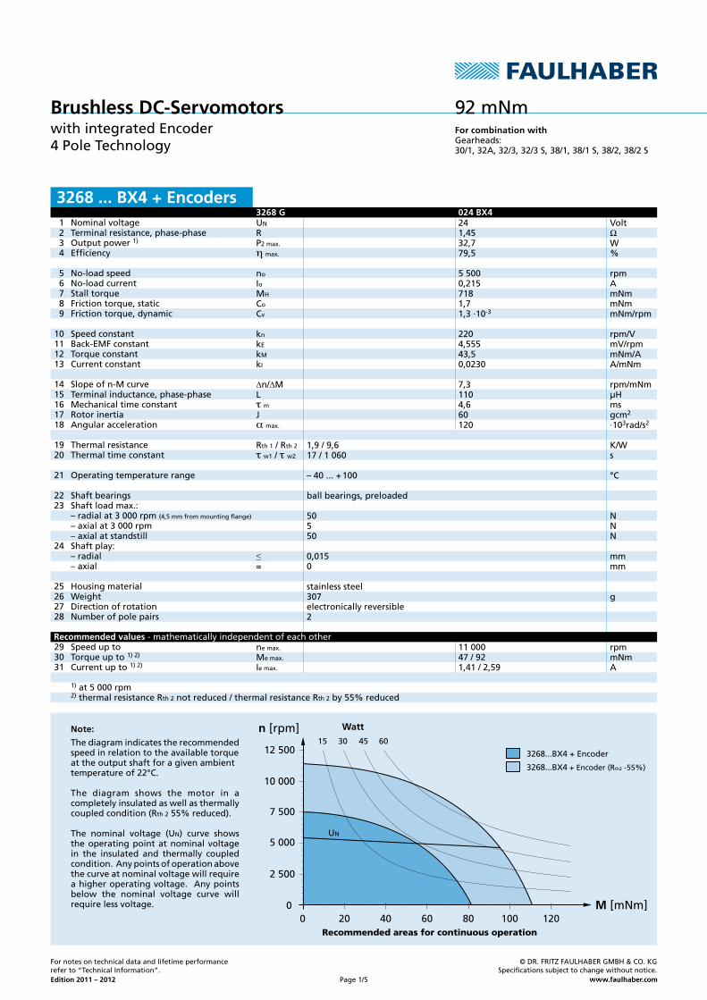
NominalvoltageTerminalresistance,phase-phaseOutputpower1)
Efficiency
No-loadspeedNo-loadcurrentStalltorqueFrictiontorque,staticFrictiontorque,dynamic
SpeedconstantBack-EMFconstantTorqueconstantCurrentconstant
Slopeofn-McurveTerminalinductance,phase-phaseMechanicaltimeconstantRotorinertiaAngularacceleration
ThermalresistanceThermaltimeconstant
Operatingtemperaturerange
ShaftbearingsShaftloadmax.:–radialat3000rpm(4,5mmfrommountingflange)
–axialat3000rpm–axialatstandstillShaftplay:–radial–axial
HousingmaterialWeightDirectionofrotationNumberofpolepairs
SpeeduptoTorqueupto1)2)
Currentupto1)2)
1)at5000rpm2)thermalresistanceRth2notreduced/thermalresistanceRth2by55%reduced
ballbearings,preloaded
stainlesssteel
electronicallyreversible
Recommended areas for continuous operation
For combination withGearheads:
Recommended values -mathematicallyindependentofeachother
Note:
Thediagramindicatestherecommendedspeedinrelationtotheavailabletorqueattheoutputshaftforagivenambienttemperatureof22°C.
The diagram shows the motor in acompletelyinsulatedaswellasthermallycoupledcondition(Rth255%reduced).
The nominal voltage (UN) curve showstheoperatingpointatnominalvoltagein the insulated and thermally coupledcondition.Anypointsofoperationabovethecurveatnominalvoltagewillrequireahigheroperatingvoltage.Anypointsbelow the nominal voltage curve willrequirelessvoltage.
Brushless DC-ServomotorswithintegratedEncoder4PoleTechnology
UN
Fornotesontechnicaldataandlifetimeperformancereferto“TechnicalInformation”.
©DR.FRITZFAULHABERGMBH&CO.KGSpecificationssubjecttochangewithoutnotice.
Page1/5
3268 ... BX4 + Encoders
Edition 2011 – 2012
18
16
Aø32
±0,1
1,5 -0,05
0
-0,05ø160
Aø0,060,02
-0,010ø5-0,006
±0,385,4 ±0,6170 ±10 13
ø22 4M36xAø0,2
60°6x
M1:1
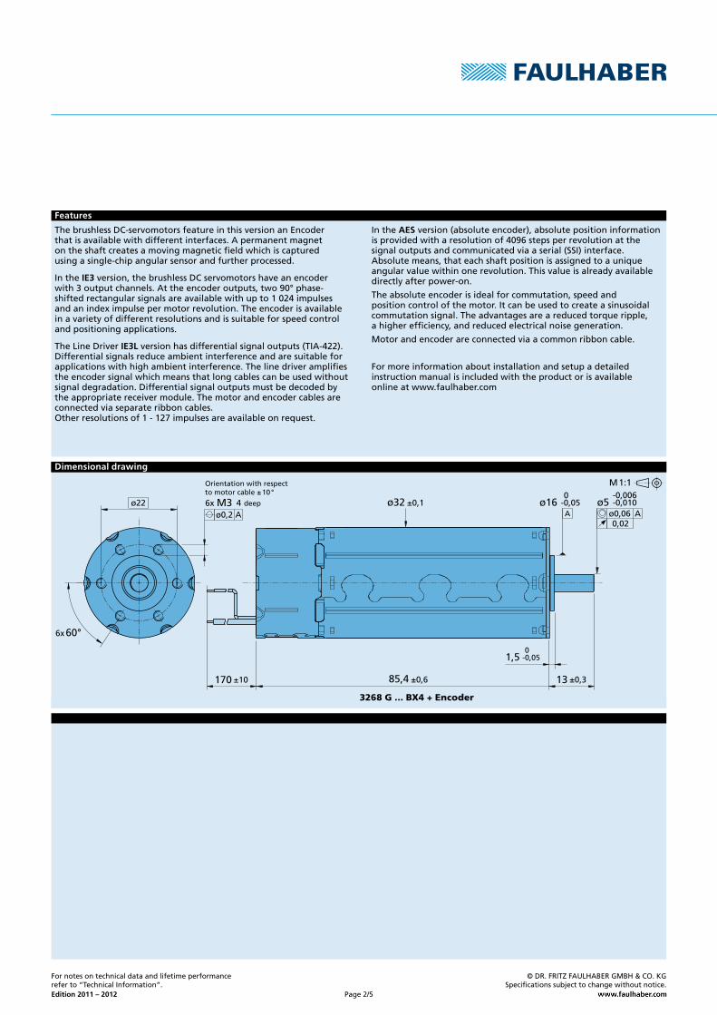
Dimensional drawing
deep
Orientationwithrespecttomotorcable±10°
3268 G ... BX4 + Encoder
Features
Fornotesontechnicaldataandlifetimeperformancereferto“TechnicalInformation”.
©DR.FRITZFAULHABERGMBH&CO.KGSpecificationssubjecttochangewithoutnotice.
Page2/5
ThebrushlessDC-servomotorsfeatureinthisversionanEncoderthatisavailablewithdifferentinterfaces.Apermanentmagnetontheshaftcreatesamovingmagneticfieldwhichiscapturedusingasingle-chipangularsensorandfurtherprocessed.
IntheIE3version,thebrushlessDCservomotorshaveanencoderwith3outputchannels.Attheencoderoutputs,two90°phase-shiftedrectangularsignalsareavailablewithupto1024impulsesandanindeximpulsepermotorrevolution.Theencoderisavailableinavarietyofdifferentresolutionsandissuitableforspeedcontrolandpositioningapplications.
TheLineDriverIE3Lversionhasdifferentialsignaloutputs(TIA-422).Differentialsignalsreduceambientinterferenceandaresuitableforapplicationswithhighambientinterference.Thelinedriveramplifiestheencodersignalwhichmeansthatlongcablescanbeusedwithoutsignaldegradation.Differentialsignaloutputsmustbedecodedbytheappropriatereceivermodule.Themotorandencodercablesareconnectedviaseparateribboncables.Otherresolutionsof1-127impulsesareavailableonrequest.
IntheAESversion(absoluteencoder),absolutepositioninformationisprovidedwitharesolutionof4096stepsperrevolutionatthesignaloutputsandcommunicatedviaaserial(SSI)interface.Absolutemeans,thateachshaftpositionisassignedtoauniqueangularvaluewithinonerevolution.Thisvalueisalreadyavailabledirectlyafterpower-on.
Theabsoluteencoderisidealforcommutation,speedandpositioncontrolofthemotor.Itcanbeusedtocreateasinusoidalcommutationsignal.Theadvantagesareareducedtorqueripple,ahigherefficiency,andreducedelectricalnoisegeneration.
Motorandencoderareconnectedviaacommonribboncable.
Formoreinformationaboutinstallationandsetupadetailedinstructionmanualisincludedwiththeproductorisavailableonlineatwww.faulhaber.com
Nf
UDDEncIDDEnc
IOUT
P0
Φtr/tf
J
UDD
kHz
VDCmAmA
°e°eµs
gcm2
VDC
IE3 - 32 IE3 - 64 IE3 - 128 IE3 - 256 IE3 - 512 IE3 - 1 02432 64 128 256 512 102415 30 60 120 240 4302+1
4,5...5,5typ.16,max.234
90±45 90±7590±45 90±750,1/0,1
0,08
2,2...18 4,5...5,5
Edition 2011 – 2012
15
24
3
6
7
8
1
18
16
Aø32
±0,1
1,5 -0,05
0
-0,05ø160
Aø0,060,02
-0,010ø5-0,006
±0,359,4 ±0,6L1 13
ø22 4M36xAø0,2
60°6x
UDD Enc
A, B, I
GND Enc
A
I
B
A
I
B
A
I
B
Po
P
Φ
Po
P
Φ
∆Φ =90°–ΦP *180°≤ 75° ∆Po =90°– Po
P *180°≤ 75°
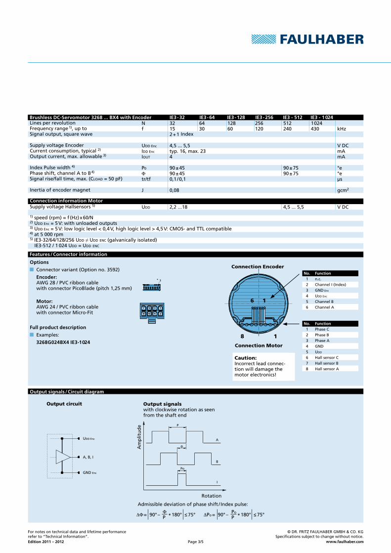
1)speed(rpm)=f(Hz)x60/N2)UDDEnc=5V:withunloadedoutputs3)UDDEnc=5V:lowlogiclevel<0,4V,highlogiclevel>4,5V:CMOS-andTTLcompatible4)at5000rpm5)IE3-32/64/128/256UDD≠UDDENC(galvanicallyisolated)IE3-512/1024UDD=UDDENC
LinesperrevolutionFrequencyrange1),uptoSignaloutput,squarewave Index
SupplyvoltageEncoderCurrentconsumption,typical2)
Outputcurrent,max.allowable3)
IndexPulsewidth4)
Phaseshift,channelAtoB4)
Signalrise/falltime,max.(CLOAD=50pF)
Inertiaofencodermagnet
SupplyvoltageHallsensors5)
Options
Connectorvariant(Optionno.3592)
Encoder: AWG28/PVCribboncable withconnectorPicoBlade(pitch1,25mm)
Motor: AWG24/PVCribboncable withconnectorMicro-Fit
Full product description
Examples:
3268G024BX4 IE3-1 024
Fornotesontechnicaldataandlifetimeperformancereferto“TechnicalInformation”.
©DR.FRITZFAULHABERGMBH&CO.KGSpecificationssubjecttochangewithoutnotice.
Page3/5
Connection information Motor
Brushless DC-Servomotor 3268 ... BX4 with Encoder
No. Function1 n.c.2 ChannelI(Index)3 GNDEnc
4 UDDEnc
5 ChannelB6 ChannelA
Caution:Incorrectleadconnec-tionwilldamagethemotorelectronics!
No. Function1 PhaseC2 PhaseB3 PhaseA4 GND5 UDD
6 HallsensorC7 HallsensorB8 HallsensorA
Connection Encoder
Connection Motor
Features / Connector information
Rotation
Output signalswithclockwiserotationasseenfromtheshaftend
Output circuit
Admissibledeviationofphaseshift/Indexpulse:
Output signals / Circuit diagram
Am
plit
ud
e
Nf
UDDEncIDDEnc
P0
Φ
J
kHz
VDCmA
°e°e
gcm2
32 64 128 256 512 102415 30 60 120 240 4302+1
4,5...5,5typ.17,max.25
90±45 90±7590±45 90±75
0,08
IE3 - 32 L IE3 - 64 L IE3 - 128 L IE3 - 256 L IE3 - 512 L IE3 - 1 024 L
I
I
B
B
A
A
UDD Enc
GND Enc
A
I
B
A
I
B
A
I
B
Po
P
Φ
Po
P
Φ
∆Φ =90°–ΦP *180°≤ 75° ∆Po =90°– Po
P *180°≤ 75°
Edition 2011 – 2012
18
110
Aø32
±0,1
1,5 -0,05
0
-0,05ø160
Aø0,060,02
-0,010ø5-0,006
±0,359,4 ±0,6170 ±10 13
ø22 4M36xAø0,2
60°6x18
110
Aø32
±0,1
1,5 -0,05
0
-0,05ø160
Aø0,060,02
-0,010ø5-0,006
±0,359,4 ±0,6170 ±10 13
ø22 4M36xAø0,2
60°6x
2
1
10
9
15
24
3
6
7
8
Fornotesontechnicaldataandlifetimeperformancereferto“TechnicalInformation”.
©DR.FRITZFAULHABERGMBH&CO.KGSpecificationssubjecttochangewithoutnotice.
Page4/5
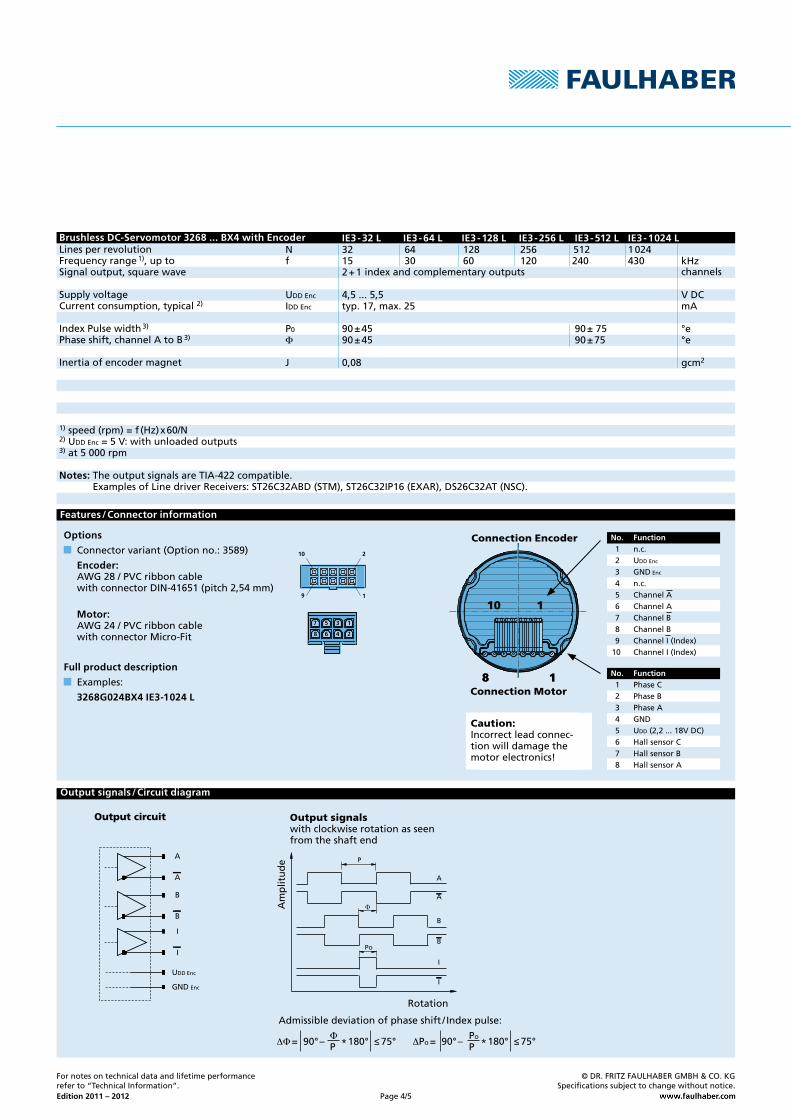
Brushless DC-Servomotor 3268 ... BX4 with EncoderLinesperrevolutionFrequencyrange1),uptoSignaloutput,squarewave indexandcomplementaryoutputs
SupplyvoltageCurrentconsumption,typical2)
IndexPulsewidth3)
Phaseshift,channelAtoB3)
Inertiaofencodermagnet
1)speed(rpm)=f(Hz)x60/N2)UDDEnc=5V:withunloadedoutputs3)at5000rpm
Notes:TheoutputsignalsareTIA-422compatible.ExamplesofLinedriverReceivers:ST26C32ABD(STM),ST26C32IP16(EXAR),DS26C32AT(NSC).
channels
Features / Connector information
Output signals / Circuit diagram
Rotation
Output signalswithclockwiserotationasseenfromtheshaftend
Output circuit
Admissibledeviationofphaseshift/Indexpulse:
Caution:Incorrectleadconnec-tionwilldamagethemotorelectronics!
Connection Motor
Connection Encoder
No. Function1 PhaseC2 PhaseB3 PhaseA4 GND5 UDD(2,2...18VDC)6 HallsensorC7 HallsensorB8 HallsensorA
No. Function1 n.c.2 UDDEnc
3 GNDEnc
4 n.c.5 ChannelA6 ChannelA7 ChannelB8 ChannelB9 ChannelI(Index)10 ChannelI(Index)
Options
Connectorvariant(Optionno.:3589)
Encoder: AWG28/PVCribboncable withconnectorDIN-41651(pitch2,54mm)
Motor: AWG24/PVCribboncable withconnectorMicro-Fit
Full product description
Examples:
3268G024BX4 IE3-1 024 L
Am
plit
ud
e
N
UDDEncIDDEnc
tsetup
VDCmAmA
MHzVVms
°C
AES-40964096
4,5...5,5typ.16,max.234
2 0...0,8 2...UDDEnc
4
–40...+100
UDD Enc
CLK
Res. (CS)
DATA
GND Enc
CLK
DATA
Res. (CS)
D0 CRC5 CRC4Res. Res.D10D11CDSStart
Data Range
Ack Stop
Timeout
CRC0
18
Aø32
±0,1
1,5 -0,05
0
-0,05ø160
Aø0,060,02
-0,010ø5-0,006
±0,359,4 ±0,6170 ±10 13
ø22 4M36xAø0,2
60°6x
15
24
3
6
7
8
Edition 2011 – 2012
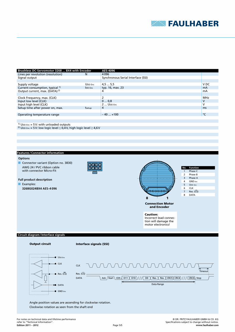
Linesperrevolution(resolution)Signaloutput SynchronousSerialInterface(SSI)
SupplyvoltageCurrentconsumption,typical1)
Outputcurrent,max.(DATA)2)
ClockFrequency,max.(CLK)Inputlowlevel(CLK)Inputhighlevel(CLK)Setuptimeafterpoweron,max.
Operatingtemperaturerange
Brushless DC-Servomotor 3268 ... BX4 with Encoder
Options
Connectorvariant(Optionno.3830)
AWG24/PVCribboncable withconnectorMicro-Fit
Full product description
Examples:
3268G024BX4 AES-4 096
Output circuit
Circuit diagram / Interface signals
Interface signals (SSI)
Features / Connector information
Anglepositionvaluesareascendingforclockwiserotation.
Clockwiserotationasseenfromtheshaftend
Connection Motor and Encoder
Caution:Incorrectleadconnec-tionwilldamagethemotorelectronics!
No. Function1 PhaseC2 PhaseB3 PhaseA4 GNDEnc
5 UDDEnc
6 CLK7 Res.(CS)8 DATA
Fornotesontechnicaldataandlifetimeperformancereferto“TechnicalInformation”.
©DR.FRITZFAULHABERGMBH&CO.KGSpecificationssubjecttochangewithoutnotice.
Page5/5
1)UDDEnc=5V:withunloadedoutputs2)UDDEnc=5V:lowlogiclevel≤0,4V,highlogiclevel≥4,6V
Top Related