


![Department of Physics, University of Illinois at Urbana ... · 0.02 0.04 0.06 0.08 0.10 1920 1930 1940 1950 1960 1970 1980 Wavenumber [cm-1] Absorbance [OD] 12 K 200 - 300 K 1920](https://static.fdocument.org/doc/165x107/5fda98fdff8ddd36c934a197/department-of-physics-university-of-illinois-at-urbana-002-004-006-008.jpg)

γλώσσες
Σελίδες
Νομικός

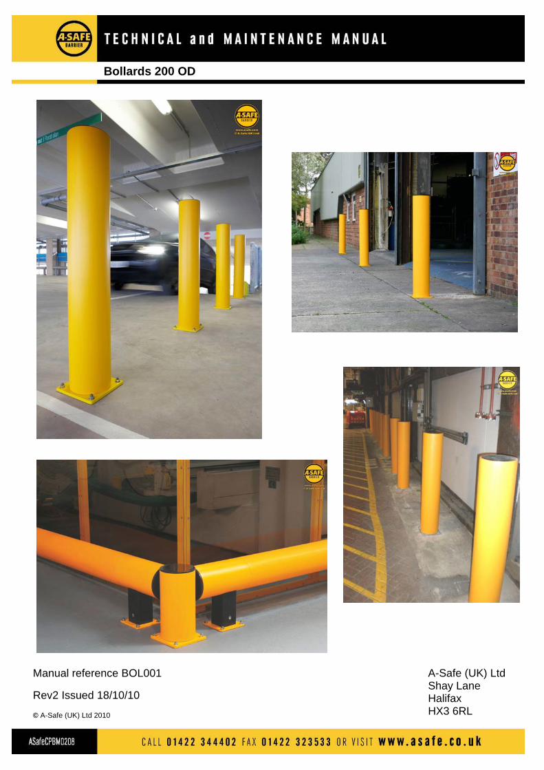
Manual reference BOL001
Rev2 Issued 18/10/10
© A-Safe (UK) Ltd 2010
A-Safe (UK) Ltd Shay Lane Halifax HX3 6RL
Bollards 200 OD
1.0 Introduction 2.0 A-Safe Company Structure and contact details 3.0 Applicable Standards and Regulations 4.0 Product Details 5.0 General Technical Product Information 6.0 Cleaning and maintenance schedule
Contents
1.0 Introduction
This manual provides information regarding applicable standards andregulations, technical product information, component and dimension detailsand care and maintenance requirements for the range of barrier andassociated products available from A-Safe (UK) Ltd. The products are installed as static internal or external fixtures and thismanual therefore makes no reference to product operation. As standard the products are supplied in a yellow/black colour combinationand some products are also available in a cool grey colour option. Thedrawings and illustrations contained in the products section of this manualwill generally show the barrier in its standard black and yellow colour format.Whatever colour option is provided the individual products concerned areidentical. The products are of modular construction and, with the exception of thecoated post steel base plates, are manufactured from lightweight extrudedplastic sections. They are quickly and easily assembled without the use of nuts and bolts,brackets or welding. Installation is achieved by anchoring the post baseplates to a sound concrete surface using the high quality steel fixing bolts,supplied with the individual products as standard. The product technical information given in this manual is common to all A-Safe (UK) Ltd manufactured products.
Contact with A-Safe may be made by post, telephone, fax or emailaddressed to the relevant contact. Alternatively information is obtainable viathe companies’ web site at www.asafe.com. A-Safe (UK) Ltd Shay Lane Halifax West Yorkshire HX3 6RL T 01422 344402 F 01422 323533 e [email protected] w www.asafe.co.uk Contacts Health and Safety James Smith [email protected] Technical Luke Smith [email protected] Sales Neil Clifford [email protected] Repairs Luke Smith [email protected]
2.0 Company Structure and Contact Details
All of the individual barrier products supplied by A-Safe have been designedand produced to be compliant with the following standards and regulations.Where applicable, specific references are made to these documents in thismanual.
• BS6180 Barriers in and about buildings – Code of Practice
• BS6399 Loading for buildings Part 1 Code of practice for dead and imposed loads
• Building Regulations 2000 – Approved Document K
• DETR Edge Protection in Multi-Storey Car Parks – Design Specification and Compliance Testing Final Report October 2001
In addition recommendations have also been made in reports published by the Institute of Civil Engineers and the Institution of Structural Engineers which were incorporated in the report Partners in Innovation published by the Office of the Deputy Prime Minister in 2002.
3.0 Applicable Standards and Regulations
4.0 Bollards 200 OD
4.2 Component Parts
4.3 Dimensions
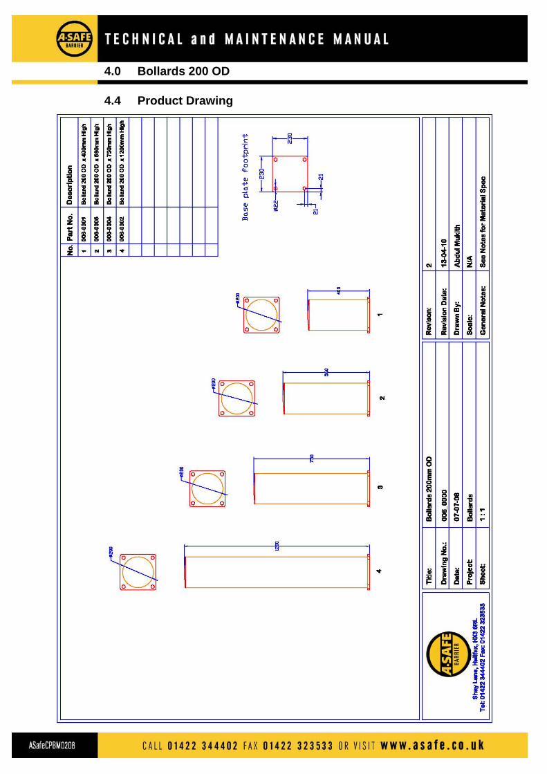
The available standard heights of the bollards are shown on the productdrawing in Section 4.4. The bollards are all 200mm outside diameter andstandard heights include 400, 560, 750 and 1200mm. These heighs arecompatible with the Traffic, Car Park, Double Rail Traffic and PedestrianBarrier products respectively. Other heights are available to suit a particularapplication. All dimensions indicated on the drawings are given in mm
The standard A-Safe Bollards are a low cost protection solution combining high impact absorption properties with little or no impact damage. They have an inbuilt impact absorption mechanism providing protection for not only what the bollard is installed to protect but also for the vehicle hitting it, reducing or removing the cost of damage repair bills. Due to their strength and high visibility the bollards are perfect for use in car parks, loading bays, at entrance and exit points and to signify designated road crossing points. They are also suitable for traffic segregation usage and are ideal to integrate with other A-Safe barrier products especially at vulnerable points such as corners and at run ends. They can be used both internally and externally.
The Bollards are all supplied as one piece pre-built assembled units. Theycomprise an internal 110mm square section post mounted on the bollardsbase plate over which is fitted the 200mm OD bollard sleeve. Sections ofimpact absorbing foam sit in the space between the inner square section postand the outer bollard sleeve. All post fixing bolts, 4 per post, needed to install a barrier section are supplied as part of the post assemblies. Details of the standard bollard heights available are shown on the drawing in section 4.4.
4.1 Introduction
4.0 Bollards 200 OD
4.4 Product Drawing
4.0 Bollards 200 OD
4.5 Fixing Bolt Technical Specification
Anchor Bolt, Hexagonal Head, Type AS M12-20/80/15 A-Safe Product Code 900_0021
Finish and Material Blue passivated zinc plated Carbon Steel, Grade 8.8
Required Drill Diameter 20mm
Required Spanner Size 19mm
Bolt Thread Size M12
Drilled Hole Depth 100mm
Total Fixture Length 123mm
Required Torque Setting 75Nm
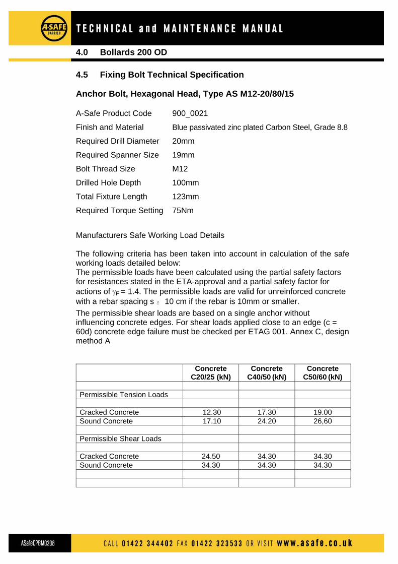
Manufacturers Safe Working Load Details The following criteria has been taken into account in calculation of the safe working loads detailed below: The permissible loads have been calculated using the partial safety factors for resistances stated in the ETA-approval and a partial safety factor for actions of γF = 1.4. The permissible loads are valid for unreinforced concrete with a rebar spacing s P 10 cm if the rebar is 10mm or smaller. The permissible shear loads are based on a single anchor without influencing concrete edges. For shear loads applied close to an edge (c = 60d) concrete edge failure must be checked per ETAG 001. Annex C, design method A
Concrete
C20/25 (kN) Concrete
C40/50 (kN) Concrete
C50/60 (kN) Permissible Tension Loads Cracked Concrete 12.30 17.30 19.00 Sound Concrete 17.10 24.20 26,60 Permissible Shear Loads Cracked Concrete 24.50 34.30 34.30 Sound Concrete 34.30 34.30 34.30
5.0 General Technical Product Information
The material used in the manufacture of the individual barrier products: • Contains no substances classified as hazardous. • Is not classified as dangerous • Burns but is not classified as flammable. Water in a spread jet, dry chemicals or foam are suitable extinguishing media. • Has a working environmental temperature range of –10 to +50 °C • Has an ignition point of 360 °C in the presence of a burner flame and 409 °C in the absence of a burner flame. • Will not give off toxic or noxious fumes should it ignite • Contains no re-cycled material but is itself 100% recyclable
5.1 Technical Information Summary
5.2 Specific Technical Information
5.2.1 UV Protection*
Barrier products may be installed externally or internally and are thereforeexposed to daylight (containing UV radiation) to a greater or lesser extent. To protect the products against UV degradation A-Safe use a UV protectionpackage in the products extruded sections as standard. This package providesa recommended performance period for UV protection of 15-20 years outdoors in Northern Europe and 10 years in the southern hemisphere. * Further technical details regarding UV Protection are available on request
5.2.2 Operational Temperature Range
The working environmental temperature range specified for the A-Safe Barrierproducts is -10°C to +50°C. The Izod impact strength of the material has beentested by the material manufacturers to the relevant standards. The products will perform below -10°C but exhibit a reduction in mechanicalperformance. Below –20°C the extruded sections from which the products areassembled reach their glass transition temperature (the temperature at whicha polymer becomes solid). Below a temperature of -10 °C the productsextruded sections are prone to cracking under point load impact conditions,however they will still stop vehicles under the impact forces the products aredesigned to withstand.
5.0 General Technical Product Information
5.2.3 Ignition Point and Flammability
The ignition point of the material from which the products extruded sectionsare manufactured is 360°C (in the case of burner flame being present) and407°C (in the absence of a burner flame). The rate at which the materialburns is 100 mm/min. The materials’ Combustible class is HB. In the unlikely event that an ignition point of 360°C or 407°C occurs, if thistemperature is reached most of the contents and structure in or around whichthe barriers are located will already have been destroyed or suffered severedamage. The barrier materials will not give off any toxic or noxious fumes should theybe ignited.
The same material type from which the barrier products extruded sections are manufactured is also used extensively in automotive parts, e.g. bumpers, radiator expansion tanks, brake fluid reservoir, windscreen washer tanks and parts of ventilation systems.
6.0 Cleaning and Routine Maintenance Schedule
6.1 General The materials used in construction of the barrier products, extrudedpolypropylene sections and steel base plates, together with the designtechniques employed in relation to barrier assembly and performanceprovide a barrier that requires minimal routine maintenance tasks to beundertaken. Routine and other maintenance is required to ensure correctproduct performance and to maintain its' appearance and high visibility.Attention is drawn to sub-section 6.4 6.2 Cleaning
Dust and other particulate material can be easily removed by simply wipingthe product with a damp cloth. Marks on the product caused by knocks and scrapes can generally beremoved using a mildly abrasive liquid or cream cleaner. Cleaning should be performed after impact or barrier repair, otherwisecleaning to preserve general barrier appearance and cleanliness can bedone at periods determined by the car park operator 6.3 Maintenance Routine maintenance is required to ensure barrier integrity and thereforeperformance is maintained over time. Areas where barrier integrity can beaffected are chipping of the powder coating an the post base plates leadingto rusting, post base plate fixing bolt nuts not being at the correct torquesettings and damage occurring to barrier component parts (post modulesand rails). It is highly unlikely that every occurrence of impact on the barrier will beknown about or even recorded. If a known impact event occurs the followingmaintenance procedures MUST be undertaken after impact on allcomponent parts of the barrier section subject to impact. If no known impactevents occur during a three month period the following maintenanceprocedures MUST be undertaken at three monthly intervals and beperformed on a minimum of at least 20% of all the barrier sections mountedon an individual car park level and at least 20% of the post base plates, baseplate anchoring bolt nuts, post components and rail components for eachbarrier section inspected. The components on which the routine threemonthly maintenance procedures are performed on each barrier section maybe chosen at random.
6.3.1 Base plates Base plates are to be inspected for chips or scratches on the base platespowder coated surface and rusting of the steel from which the base platesare manufactured. Chips or scratches to the powder-coated surface are to be covered overusing a suitable paint to protect the steel material exposed by the chip orscratch. If rusting to a base plate is found that is causing erosion or crumbling of thebase plates steel material, allowing manual movement of the barrier andassociated base plate or affecting the ability of any of the fixing bolts tocorrectly anchor a base plate post module to which the base plate isattached MUST be replaced with a new post module. PLEASE NOTE. Should any of the defects detailed above be found oninspection of a randomly selected component ALL components on thebarrier section must be inspected for defects. 6.3.2 Fixing Bolt Integrity All four base plate fixing bolts on each base plate inspected should beinspected for slippage, pull out and correct positioning in the holes in whichthey are located. If a fixing bolt is not properly located the bolt should be hammered back in,or further into, the hole in which it is located and the fixing bolt nut correctlytorqued to the settting specified in the relevant product section of thismanual. If a fixing bolt nut cannot be tightened to the correct torque afterrelocation A-Safe (UK) Limited are to be contacted regarding the correctprocedures to be followed. PLEASE NOTE. Should the location and integrity of a fixing bolt found to beincorrect on inspection then the location of all fixing bolts on that barriersection must be checked and corrected. 6.3.3 Fixing Bolt Nuts Torque Setting The torque settings of all four base plate fixing bolt nuts on each base plateinspected should be checked to be at the correct setting as specified in therelevant product section of this manual. If lower than than the specifiedsetting the nuts should be re-tightened to the correct setting specified. PLEASE NOTE. Should any of the torque settings checked be found to beincorrect, the nut torque settings on all the fixing bolts anchoring the barriersection must be checked and re-tightened as necessary. If a nut cannot bere-tightened to the correct torque setting refer to section 6.3.2.
6.0 Cleaning and Routine Maintenance Schedule
6.0 Cleaning and Routine Maintenance Schedule
6.3.4 Condition & Integrity of individual barrier components The plastic material of the barrier post modules should be visually inspectedfor signs of stress, usually indicated by white marking on the material at thepoint of stress, and straightness and correct location within the assembledbarrier section. Stressed or non-straight components are to be replaced with newcomponents. Incorrectly located components are to be correctly relocated within thebarrier section assembly. If correct relocation cannot be achieved due tofixing bolt integrity problems, refer to section 6.3.2. PLEASE NOTE. Should a barrier component be found to be defective thenall components on that barrier section should be inspected for defects andremedial action be taken as indicated above.
Top Related