


γλώσσες
Σελίδες
Νομικός


Aplicações daEq. de Bernoulli
Ex. 5.42 MEDIÇÃO DA PRESSÃO: MANÔMETRO DIFERENCIAL – CASO PRÁTICO
h
PA PBρf
ρm
• Determine PA-PB em função da altura h e das densidades dos fluidos.Resp.: PA-PB = (ρm - ρf).g.h
Pergunta: se os fluidos forem água e mercúrio, como fica a expressão?Resp.: PA-PB = (13600 - 1000).g.h
• Pergunta: e se os fluidos forem ar e água?Resp.: PA-PB = (1000 – 1.2)gh como ρliq>>ρgas → PA-PB ≈ ρmgh
• Um engano freqüente dos alunos:aplicar a relação acima quando realizam medidas com dois líquidos.
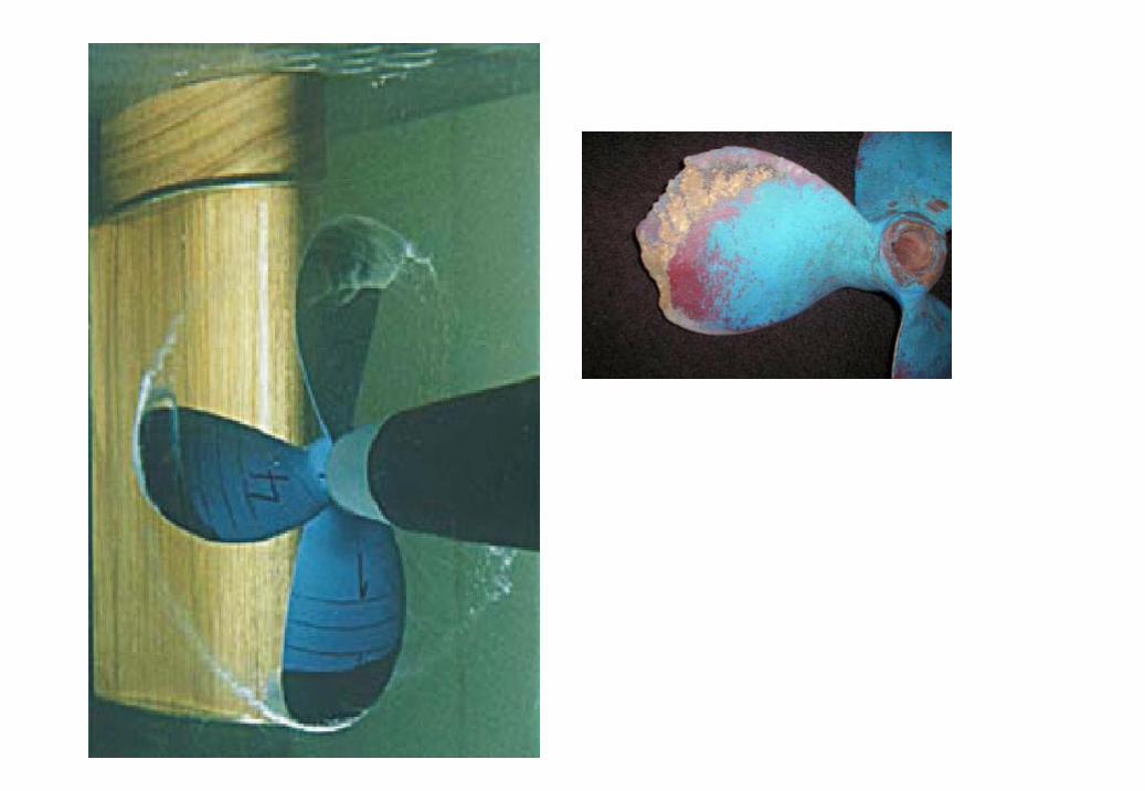
The cavitation phenomenonThe cavitationphenomenon is characterized by the formation and quick growth of vapor bubbles in the presence of a depression, followed by a violent implosion. Such an implosion, often supersonic, can generate a spherical shock wave in the liquid developing pressures higher than the solid material yield stress.
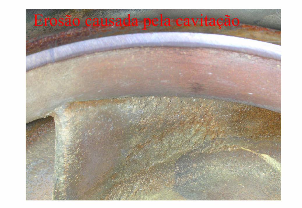
Erosão causada pela cavitação
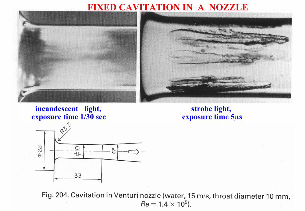
FIXED CAVITATION IN A NOZZLE
incandescent light, strobe light, exposure time 1/30 sec exposure time 5µs
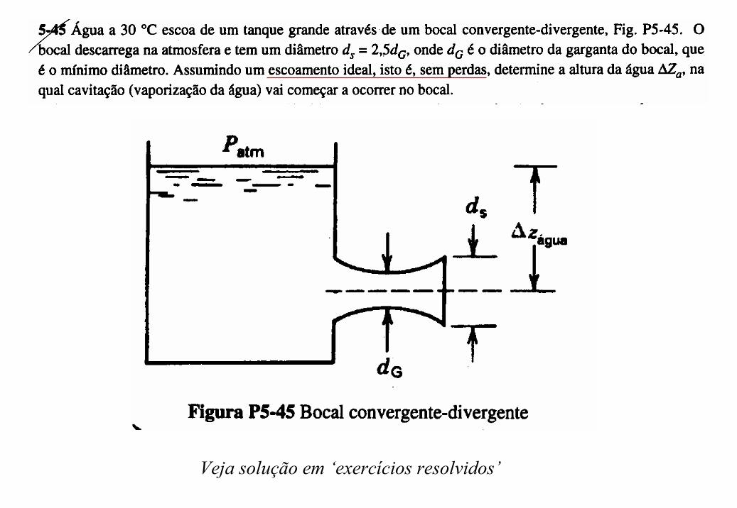
Veja solução em ‘exercícios resolvidos’
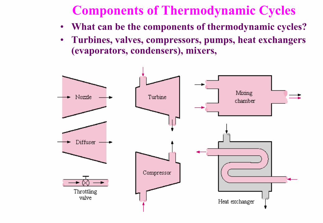
Components of Thermodynamic Cycles• What can be the components of thermodynamic cycles?• Turbines, valves, compressors, pumps, heat exchangers
(evaporators, condensers), mixers,
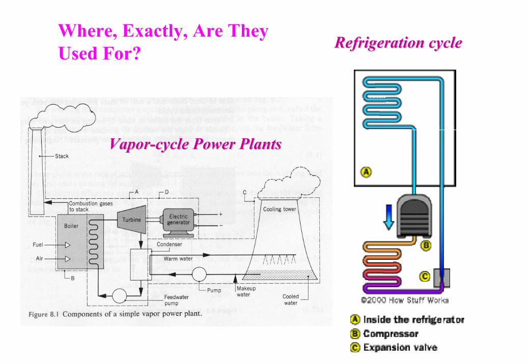
VaporVapor--cycle Power Plantscycle Power Plants
Refrigeration cycleRefrigeration cycleWhere, Exactly, Are They Used For?
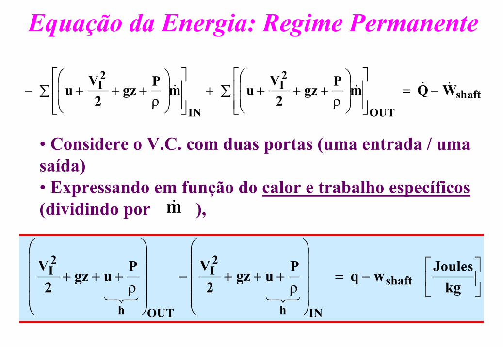
Equação da Energia: Regime Permanente
shaftOUT
2I
IN
2I WQ mPgz
2V
u mPgz2
Vu &&&& −=∑
ρ++++∑
ρ+++−
−=
ρ+++−
ρ+++
kgJoules wq Pugz
2VPugz
2V
shaft
INh
2I
OUTh
2I
321321
• Considere o V.C. com duas portas (uma entrada / uma saída)• Expressando em função do calor e trabalho específicos(dividindo por ), m&

Representação Genérica dos Componentesde Ciclos Termodinâmicos
• Aplicação de um balanço de energia para dispositivos que operam com fluxo de energia (entalpia), produzem trabalho e trocam calor com um reservatório a T0
mh1
mh2
Q
W
T0
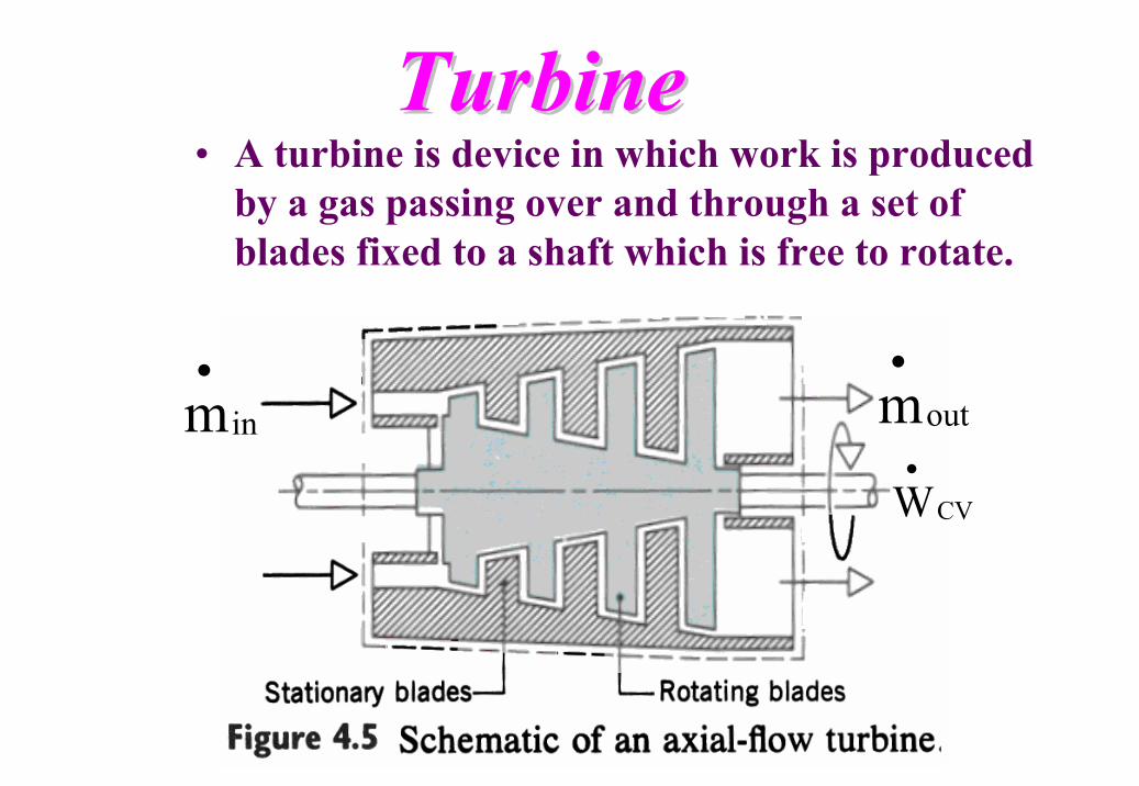
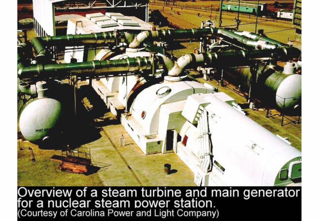
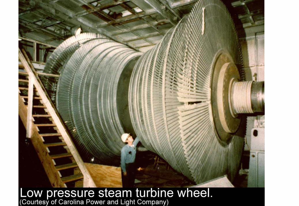
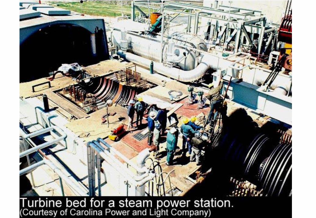
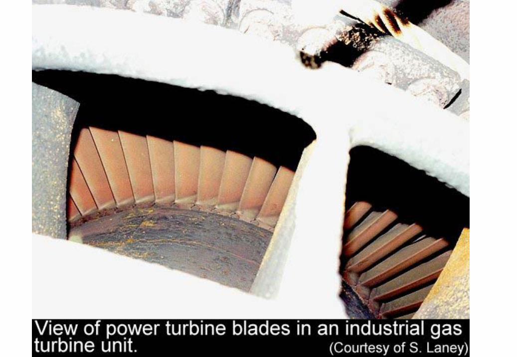
TurbineTurbine• A turbine is device in which work is produced
by a gas passing over and through a set of blades fixed to a shaft which is free to rotate.
inm•
outm•
CVW•
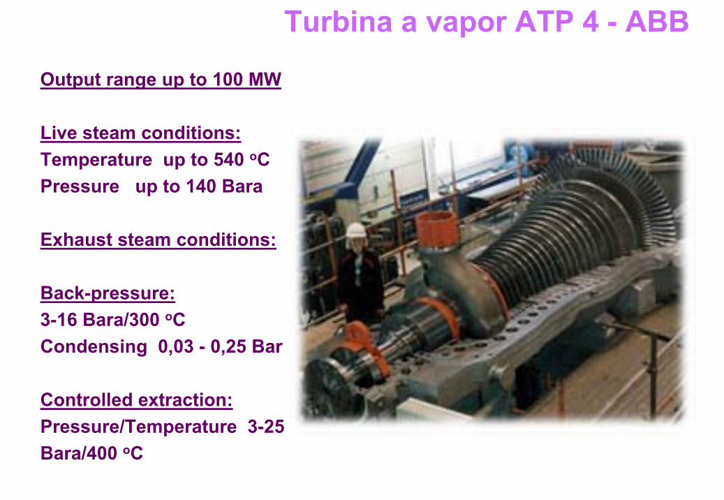
Output range up to 100 MW
Live steam conditions:Temperature up to 540 oC Pressure up to 140 Bara
Exhaust steam conditions:
Back-pressure:3-16 Bara/300 oC Condensing 0,03 - 0,25 Bar
Controlled extraction:Pressure/Temperature 3-25 Bara/400 oC
Turbina a vapor ATP 4 - ABB
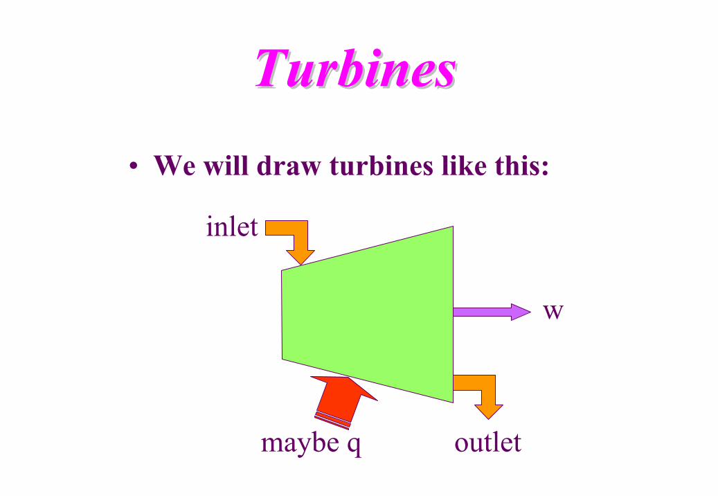
TurbinesTurbines• We will draw turbines like this:
inlet
outlet
w
maybe q
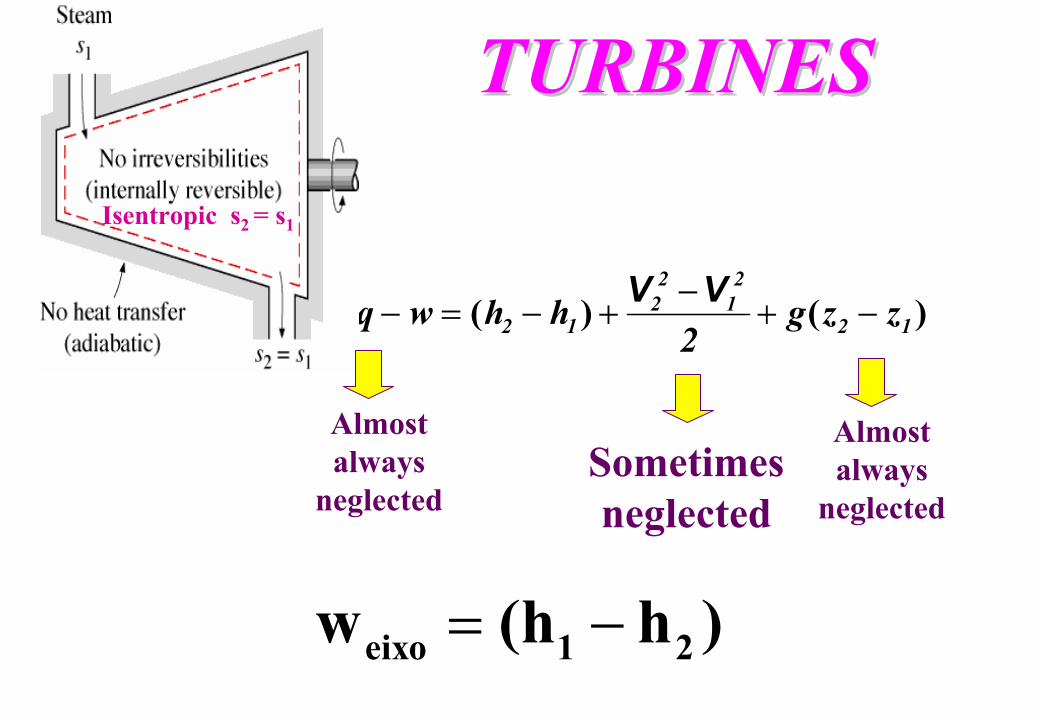
TURBINESTURBINES
)()( 12
21
22
12 zzg2
hhwq −+−
+−=−VV
Sometimes neglected
eixo 1 2w (h h )= −
Almost always
neglected
Isentropic s2 = s1
Almost always
neglected
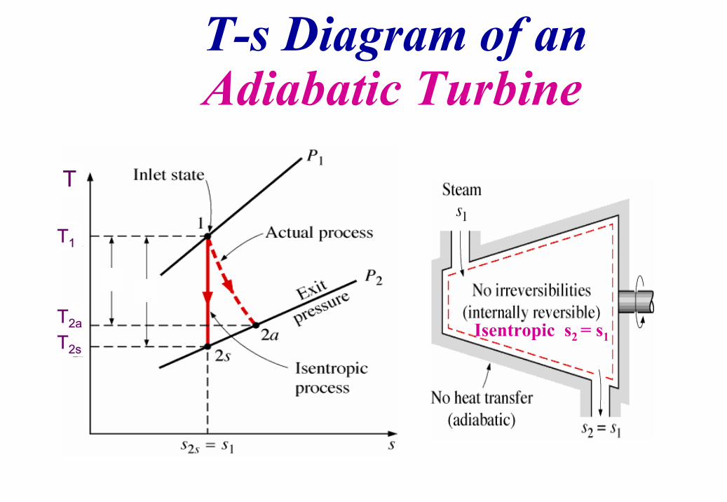
T-s Diagram of an Adiabatic Turbine
Isentropic s2 = s1
T
T1
T2aT2s
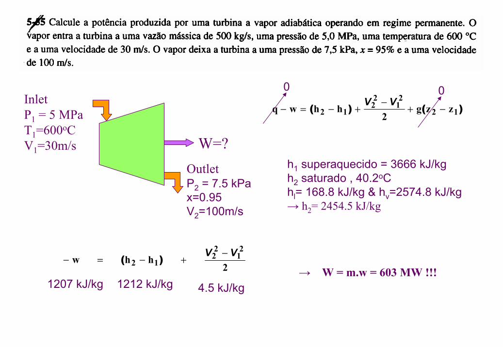
W=?
InletP1 = 5 MPaT1=600oCV1=30m/s
OutletP2 = 7.5 kPax=0.95V2=100m/s
)()( 12
21
22
12 zzg2
hhwq −+−
+−=−VV
0 0
h1 superaquecido = 3666 kJ/kgh2 saturado , 40.2oChl= 168.8 kJ/kg & hv=2574.8 kJ/kg→ h2= 2454.5 kJ/kg
2 hh w
21
22
12VV −
+−=− )(
1212 kJ/kg 4.5 kJ/kg1207 kJ/kg→ W = m.w = 603 MW !!!
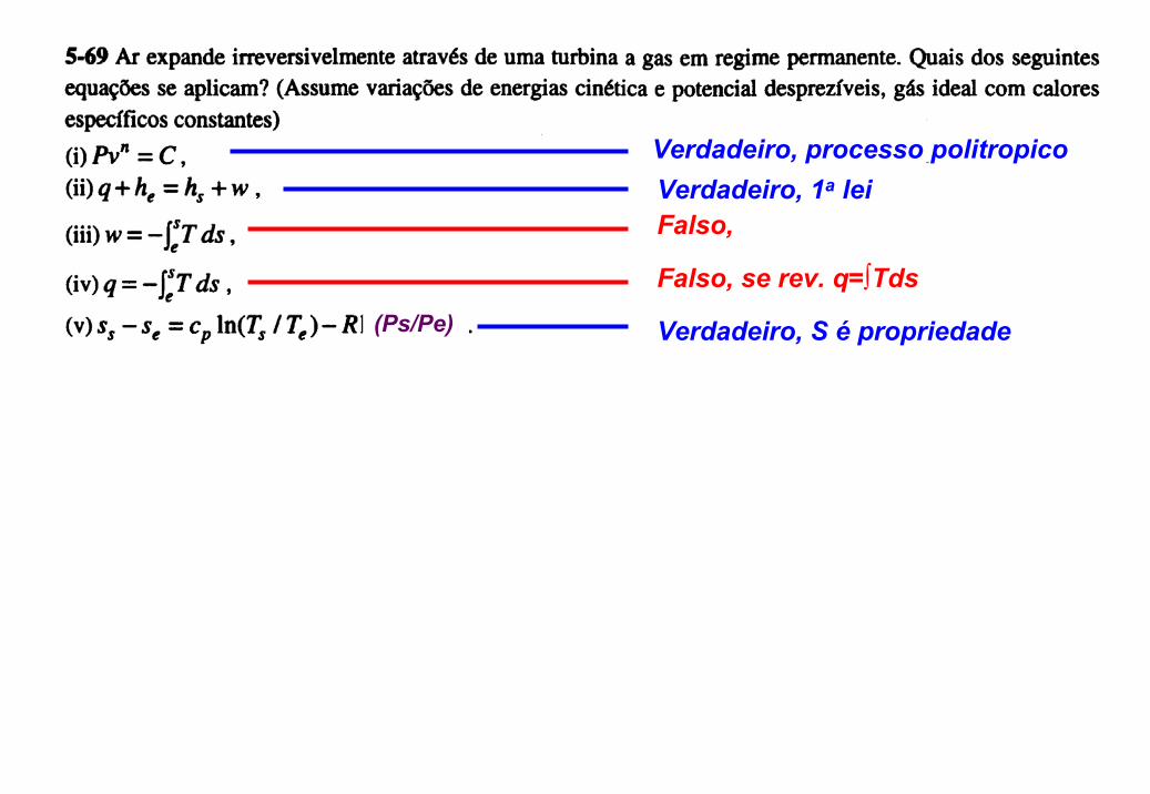
Verdadeiro, processo politropicoVerdadeiro, 1a leiFalso,
Falso, se rev. q=∫Tds
Verdadeiro, S é propriedade(Ps/Pe)
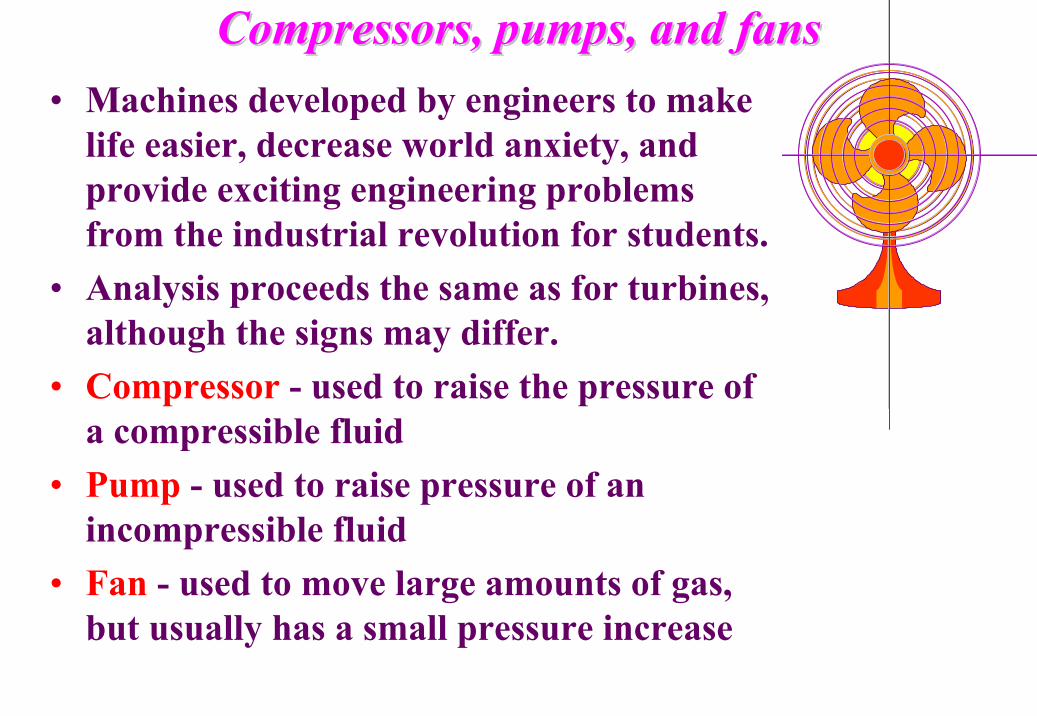
• Machines developed by engineers to make life easier, decrease world anxiety, and provide exciting engineering problems from the industrial revolution for students.
• Analysis proceeds the same as for turbines, although the signs may differ.
• Compressor - used to raise the pressure of a compressible fluid
• Pump - used to raise pressure of an incompressible fluid
• Fan - used to move large amounts of gas, but usually has a small pressure increase
Compressors, pumps, and fansCompressors, pumps, and fans
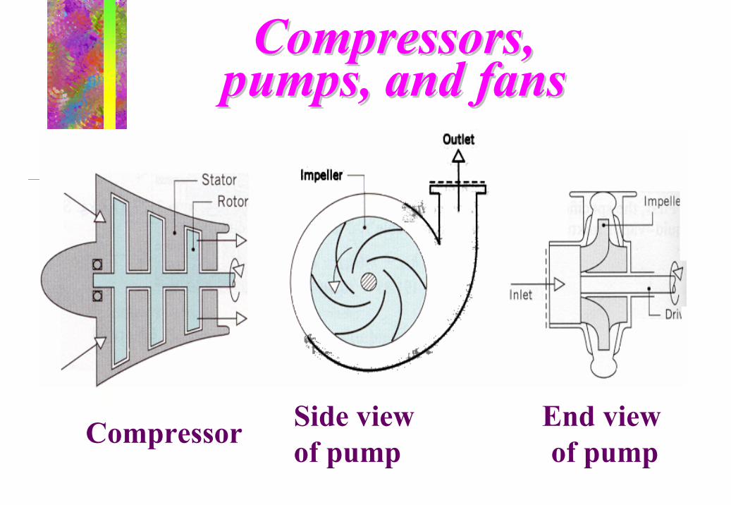
Compressors, Compressors, pumps, and fanspumps, and fans
Compressor Side view End view of pump of pump
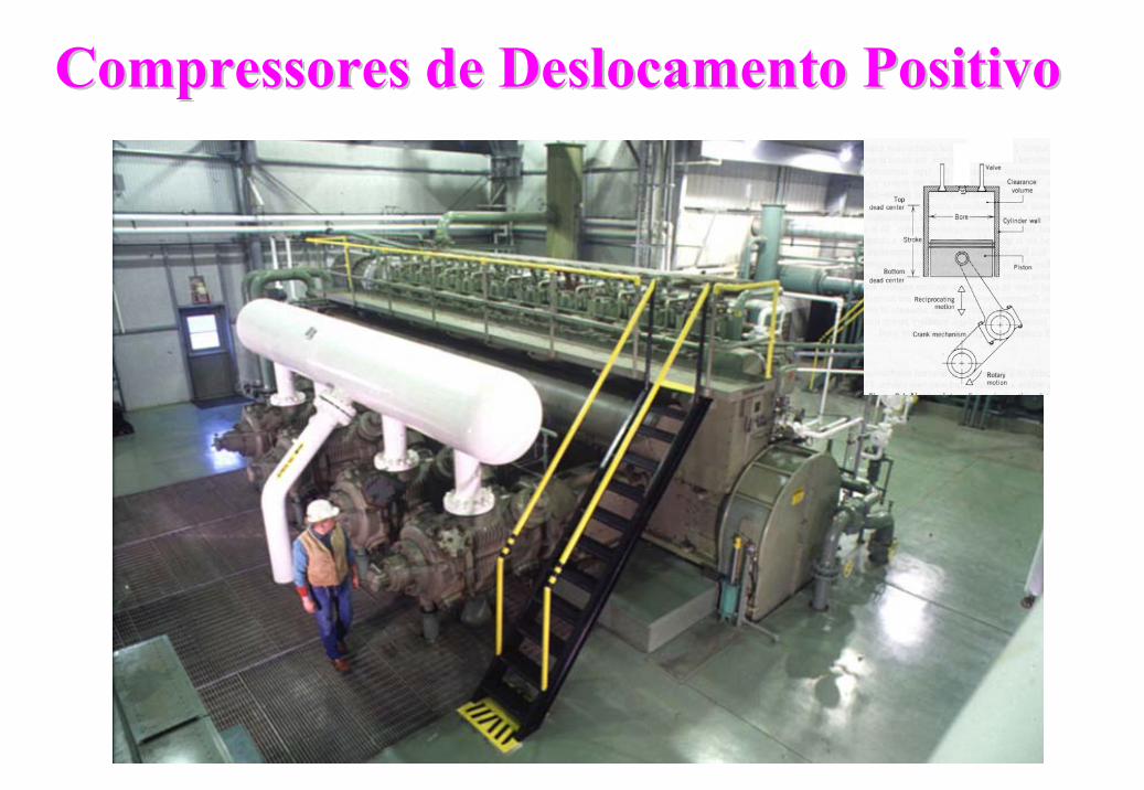
Compressores de Deslocamento PositivoCompressores de Deslocamento Positivo
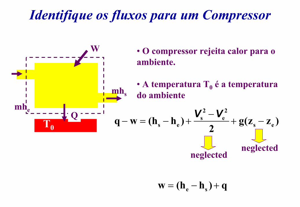
Identifique os fluxos para um Compressor
mhe
mhs
Q
W
T0
• O compressor rejeita calor para o ambiente.
• A temperatura T0 é a temperatura do ambiente
2 2s e
s e s eq w (h h ) g(z z )2−
− = − + + −V V
neglectedneglected
e sw (h h ) q= − +
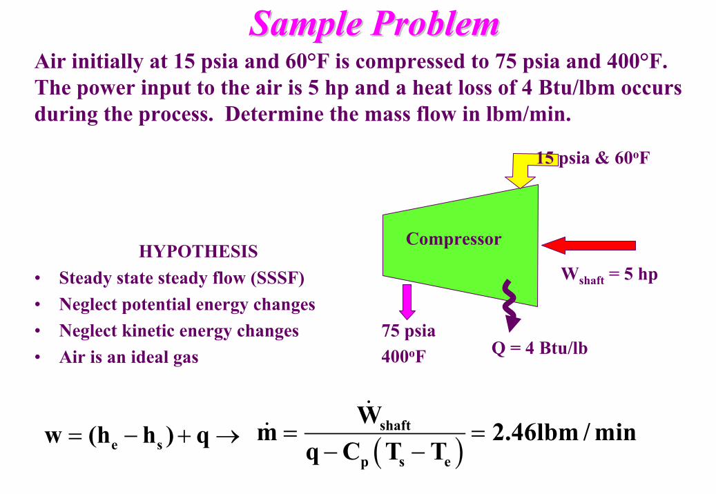
Sample ProblemSample ProblemAir initially at 15 psia and 60°F is compressed to 75 psia and 400°F. The power input to the air is 5 hp and a heat loss of 4 Btu/lbm occurs during the process. Determine the mass flow in lbm/min.
Wshaft = 5 hp
75 psia400oF Q = 4 Btu/lb
CompressorHYPOTHESIS
• Steady state steady flow (SSSF)• Neglect potential energy changes• Neglect kinetic energy changes• Air is an ideal gas
e sw (h h ) q= − + → ( )shaft
p s e
Wm 2.46lbm / min
q C T T= =
− −
&&
15 psia & 60oF
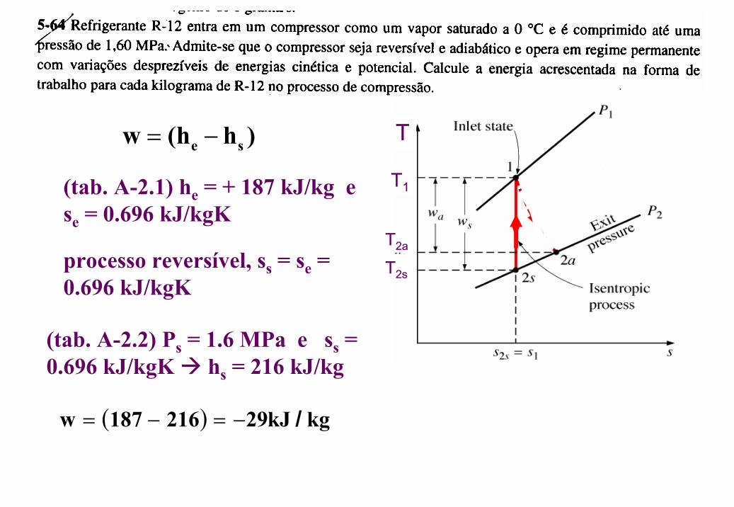
e sw (h h )= −
(tab. A-2.1) he = + 187 kJ/kg e se = 0.696 kJ/kgK
processo reversível, ss = se = 0.696 kJ/kgK
(tab. A-2.2) Ps = 1.6 MPa e ss = 0.696 kJ/kgK hs = 216 kJ/kg
( ) kgkJ29216187w /−=−=
T
T1
T2aT2s

Cars & IntercoolersCars & Intercoolers
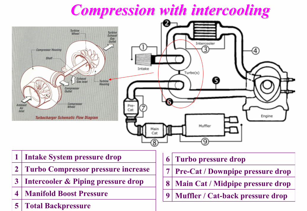
Total Backpressure5Manifold Boost Pressure4Intercooler & Piping pressure drop3Turbo Compressor pressure increase2Intake System pressure drop1
Muffler / Cat-back pressure drop9Main Cat / Midpipe pressure drop8Pre-Cat / Downpipe pressure drop7Turbo pressure drop6
Compression with Compression with intercoolingintercooling
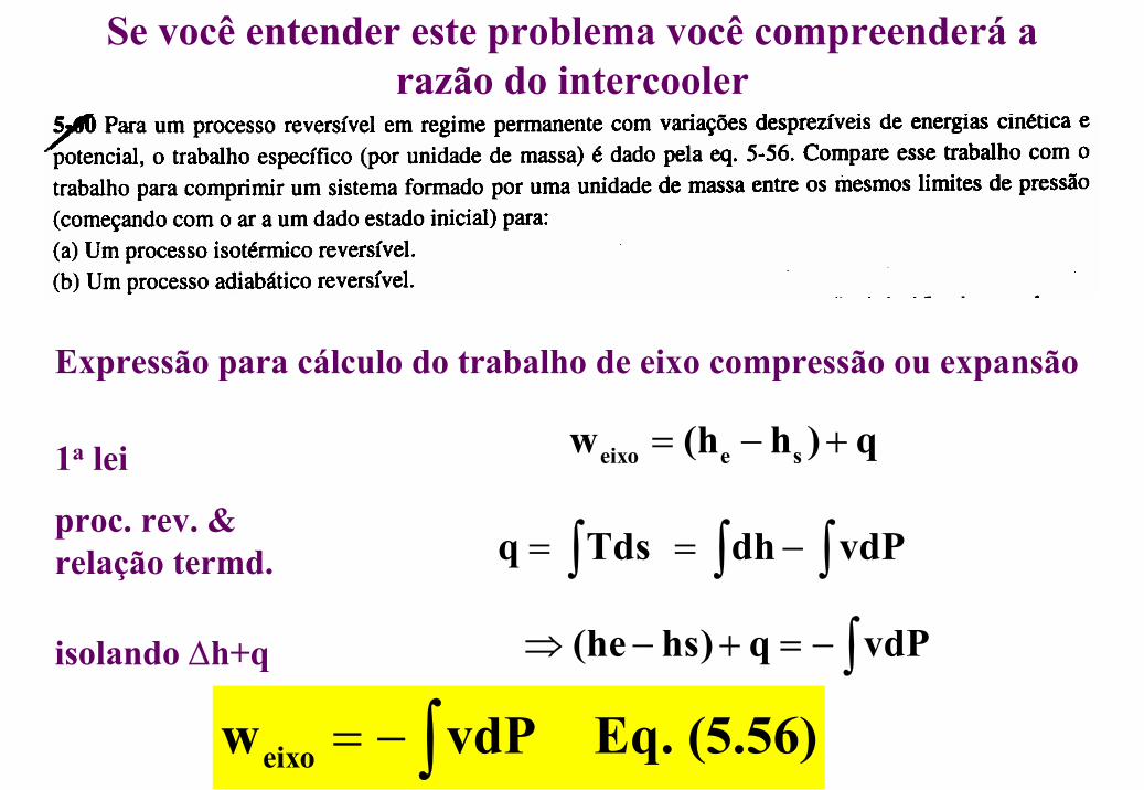
Se você entender este problema você compreenderá a razão do intercooler
Expressão para cálculo do trabalho de eixo compressão ou expansão
1a lei
proc. rev. & relação termd.
isolando ∆h+q
eixo e sw (h h ) q= − +
q Tds= ∫ dh vdP= −∫ ∫(he hs) q vdP⇒ − + = −∫
eixow vdP Eq. (5.56)= −∫
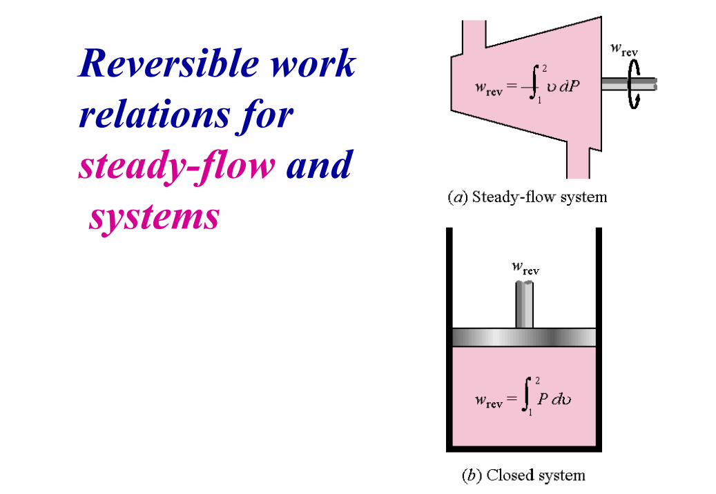
Reversible work relations for steady-flow and systems
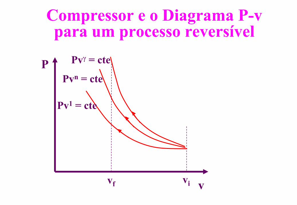
Compressor e o Diagrama P-v para um processo reversível
P
vvivf
Pv1 = cte
Pvn = cte
Pvγ = cte
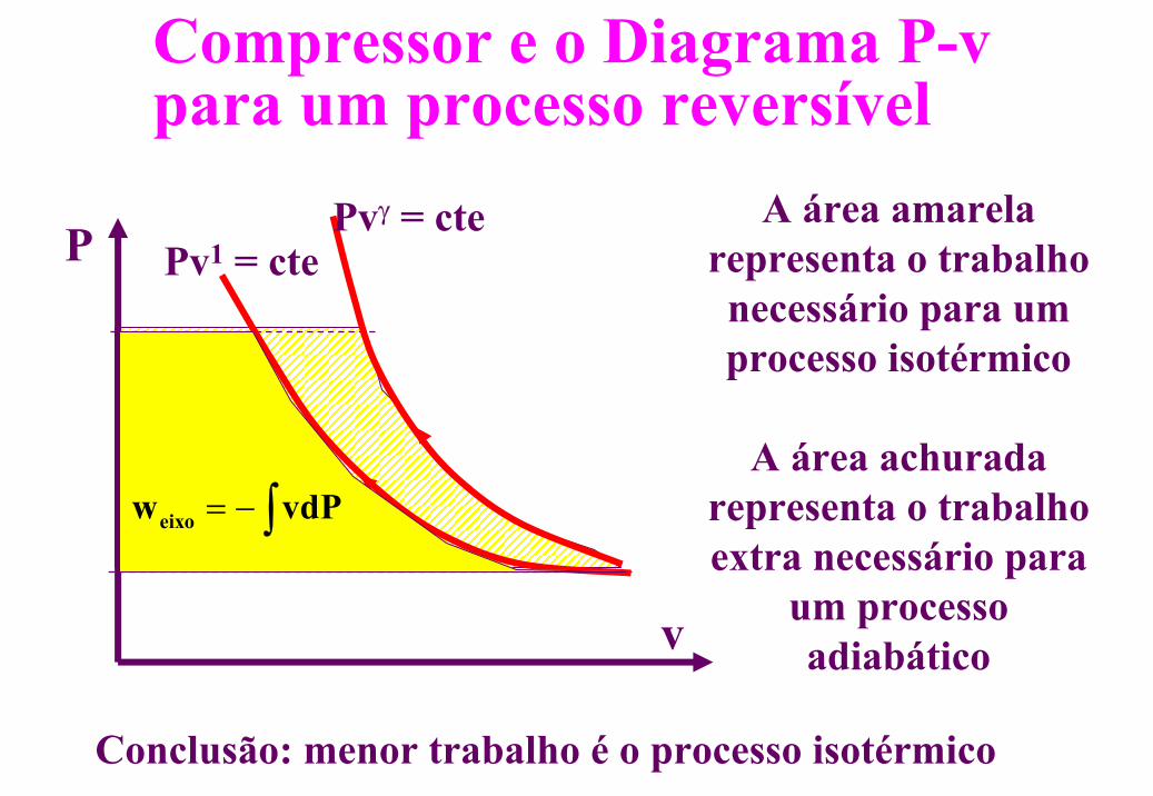
Compressor e o Diagrama P-v para um processo reversível
P
v
Pv1 = ctePvγ = cte A área amarela
representa o trabalho necessário para um processo isotérmico
eixow vdP= −∫A área achurada
representa o trabalho extra necessário para
um processo adiabático
Conclusão: menor trabalho é o processo isotérmico
eixow vdP= −∫
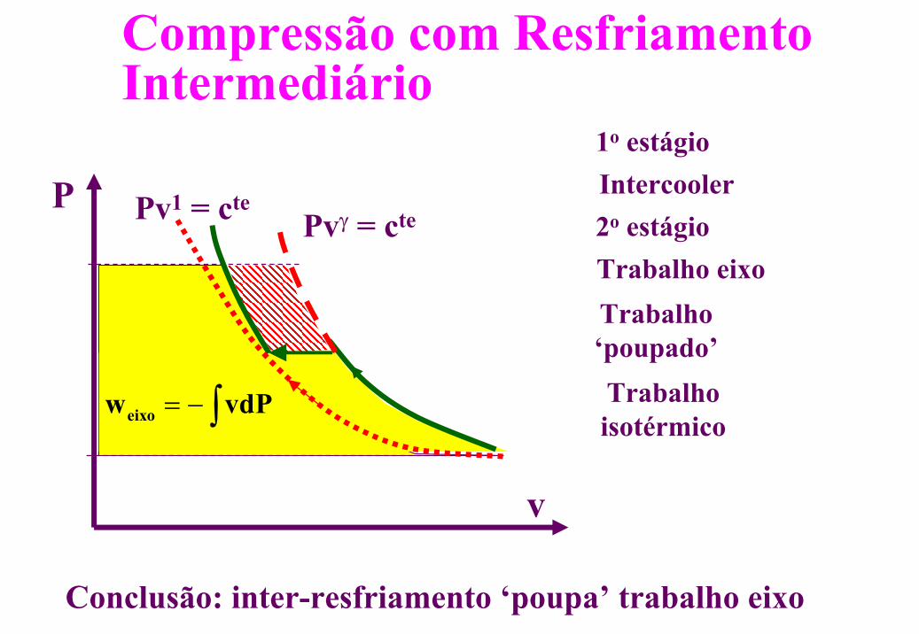
Compressão com ResfriamentoIntermediário
P
v
Pv1 = ctePvγ = cte
1o estágio
Trabalho ‘poupado’
Conclusão: inter-resfriamento ‘poupa’ trabalho eixo
Intercooler2o estágioTrabalho eixo
Trabalhoisotérmico
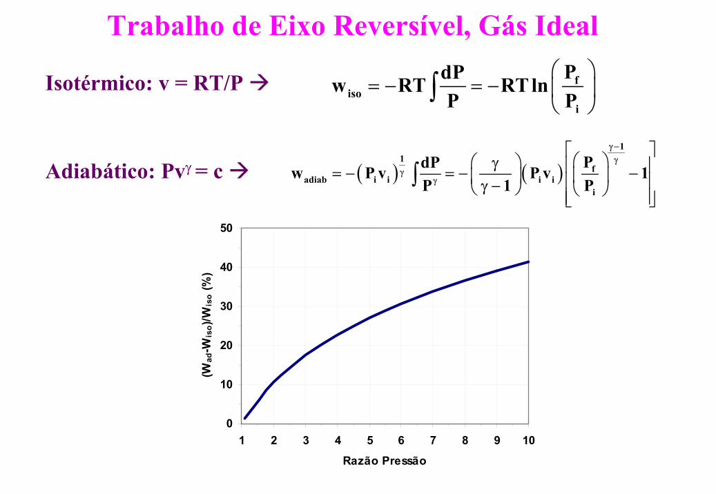
Trabalho de Eixo Reversível, Gás Ideal
Isotérmico: v = RT/P fiso
i
PdPw RT RTlnP P
= − = −
∫
Adiabático: Pvγ = c ( ) ( )1
1f
adiab i i i ii
PdPw P v P v 1P 1 P
γ−γ
γγ
γ = − = − − γ −
∫
0
10
20
30
40
50
1 2 3 4 5 6 7 8 9 10
Razão Pressão
(Wad
-Wis
o)/W
iso
(%)
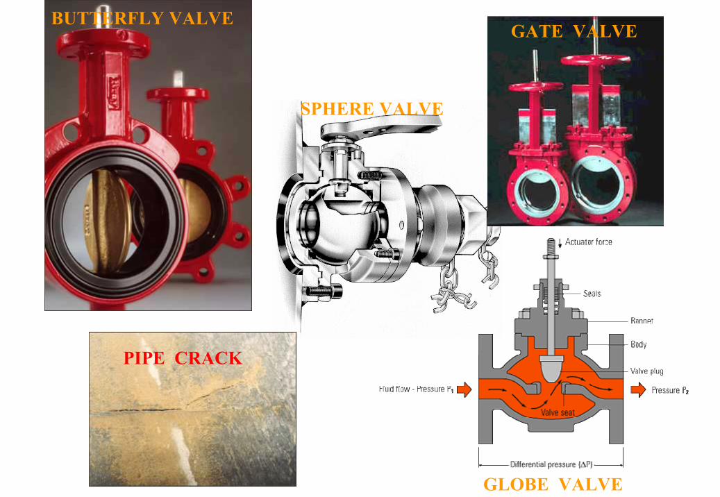
BUTTERFLY VALVE
SPHERE VALVE
GLOBE VALVE
PIPE CRACK
GATE VALVE

Thro
ttlin
g D
evic
es (V
alve
s)Th
rottl
ing
Dev
ices
(Val
ves)
Typical assumptions for throttling devicesTypical assumptions for throttling devices1. No work2. Potential energy changes are zero3. Kinetic energy changes are usually small4. Heat transfer is usually small5. Two port device
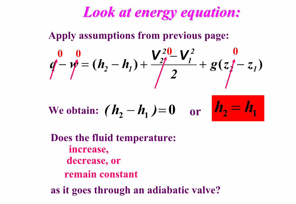
Look at energy equation:Look at energy equation:
)()( 12
21
22
12 zzg2
hhwq −+−
+−=−VV
Apply assumptions from previous page:
0 0 00
We obtain: 012 =− )hh( or 12 hh =
Does the fluid temperature:increase, decrease, or
as it goes through an adiabatic valve?remain constant
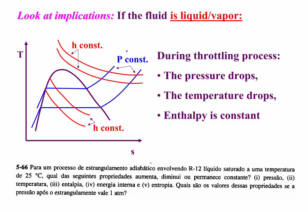
Look at implications:Look at implications: If the fluid is liquid/vapor:
During throttling process:
• The pressure drops,
• The temperature drops,
• Enthalpy is constant
s
T
h const.
h const.P const.
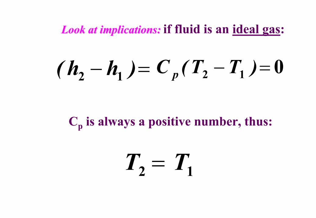
Look at implications:Look at implications: if fluid is an ideal gas:
012 =− )TT(C p=− )hh( 12
Cp is always a positive number, thus:
12 TT =
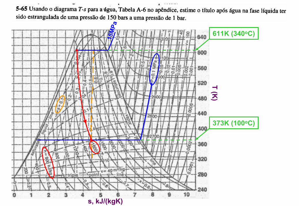
s, kJ/(kgK)
T (K)
15M
Pa
611K (340oC)
373K (100oC)
John Connor (T1000) in Terminator 2
Fenômeno de Fragilização de Metaispor Baixas Temperaturas
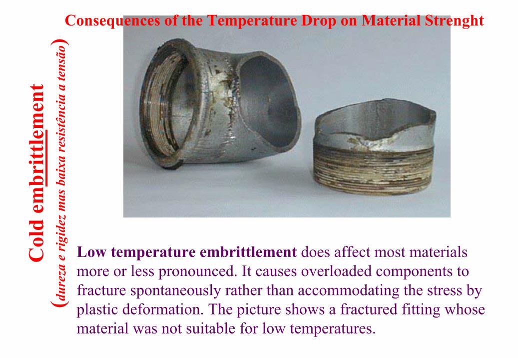
Col
d em
britt
lem
ent
( dure
zae
rigi
dezm
asba
ixa
resi
stên
cia
a te
nsão
)
Low temperature embrittlement does affect most materials more or less pronounced. It causes overloaded components to fracture spontaneously rather than accommodating the stress by plastic deformation. The picture shows a fractured fitting whosematerial was not suitable for low temperatures.
Consequences of the Temperature Drop on Material Strenght
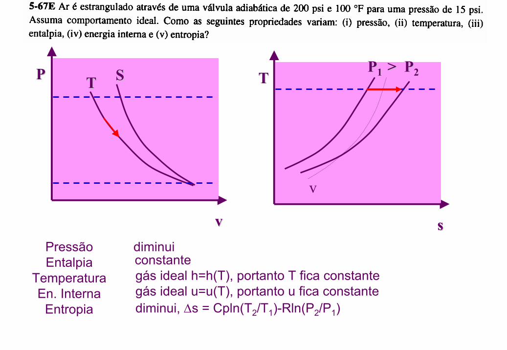
PP
vv
SSTT
diminuiPressãoEntalpia
TemperaturaEn. Interna
Entropia
constantegás ideal h=h(T), portanto T fica constantegás ideal u=u(T), portanto u fica constante
TT
ss
v
PP1 1 > P> P22
diminui, ∆s = Cpln(T2/T1)-Rln(P2/P1)
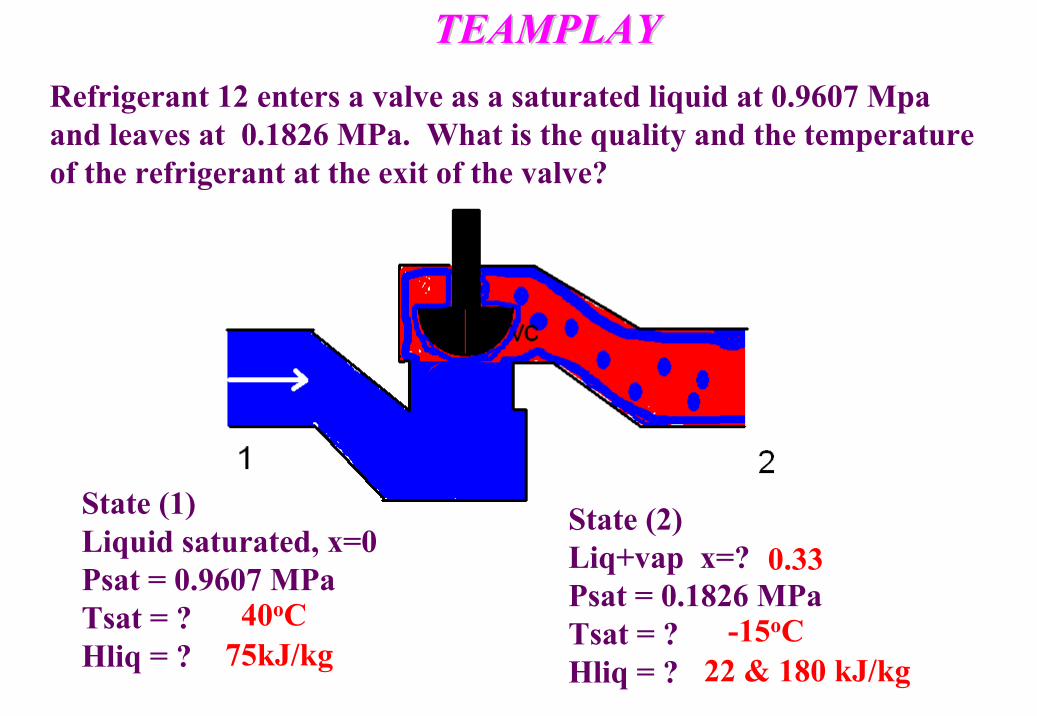
TEAMPLAYTEAMPLAYRefrigerant 12 enters a valve as a saturated liquid at 0.9607 Mpaand leaves at 0.1826 MPa. What is the quality and the temperature of the refrigerant at the exit of the valve?
State (1)Liquid saturated, x=0Psat = 0.9607 MPaTsat = ?Hliq = ?
State (2)Liq+vap x=?Psat = 0.1826 MPaTsat = ?Hliq = ?
40oC75kJ/kg
-15oC22 & 180 kJ/kg
0.33
Heat exchangers are used Heat exchangers are used in a variety of industriesin a variety of industries
• Automotive - radiator• Refrigeration - evaporators/condensers• Power production - boilers/condensers• Power electronics - heat sinks• Chemical/petroleum industry- mixing processes
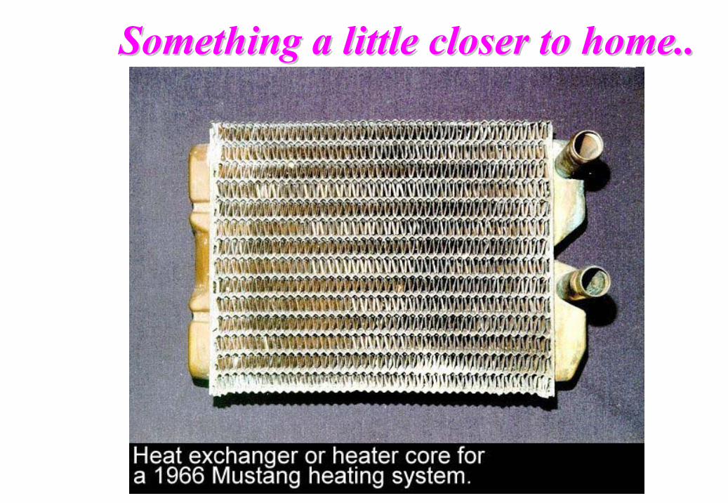
Something a little closer to home..Something a little closer to home..
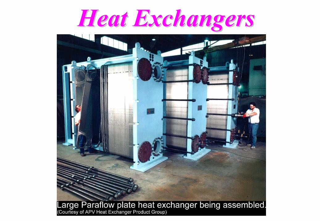
Heat Exchangers Heat Exchangers
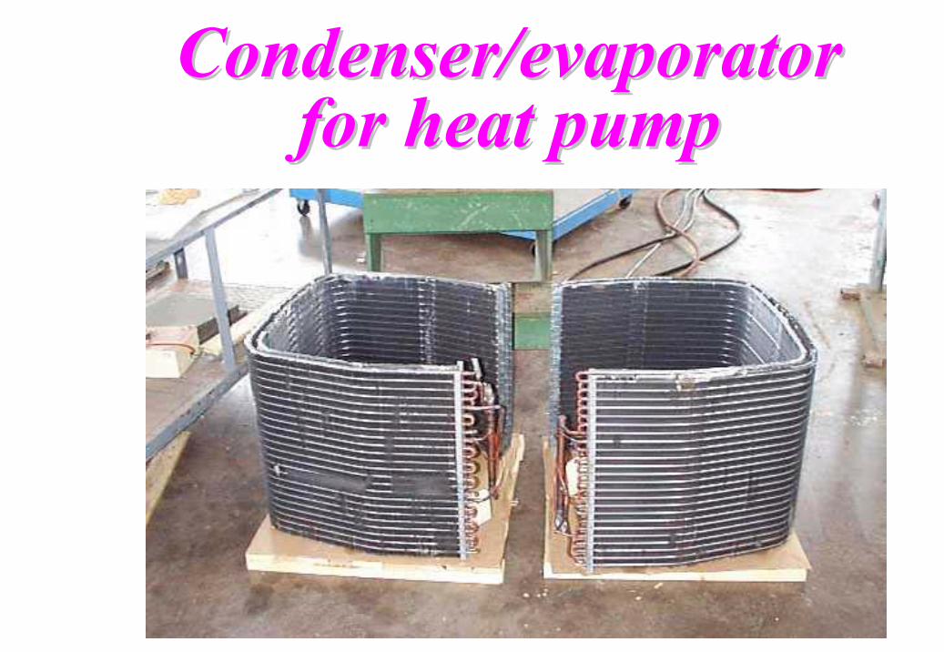
Condenser/evaporator Condenser/evaporator for heat pumpfor heat pump
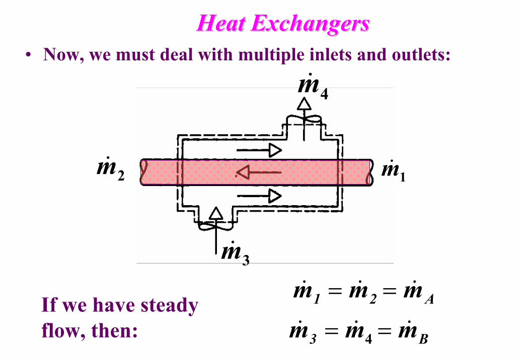
Heat ExchangersHeat Exchangers• Now, we must deal with multiple inlets and outlets:
1m&2m&
4m&
3m&
A21 mmm &&& ==
B3 mmm &&& == 4
If we have steady flow, then:
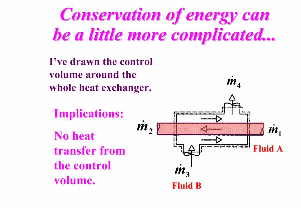
Conservation of energy can Conservation of energy can be a little more complicated...be a little more complicated...
1m&2m&
4m&
3m&
I’ve drawn the control volume around the whole heat exchanger.
Implications:
No heat transfer from the control volume.
Fluid A
Fluid B
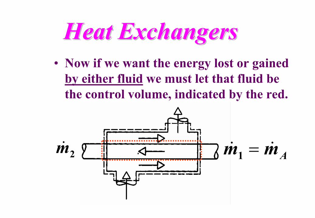
Heat ExchangersHeat Exchangers• Now if we want the energy lost or gained
by either fluid we must let that fluid be the control volume, indicated by the red.
Amm && =12m&
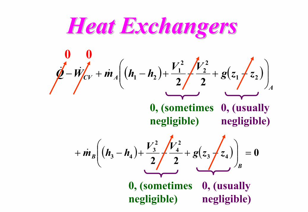
Heat ExchangersHeat Exchangers
( ) ( )A
ACV zzgVVhhmWQ
−+−+−+− 21
22
21
21 22&&&
( ) ( ) 022 43
24
23
43 =
−+−+−+
BB zzgVVhhm&
0
0, (sometimes negligible)
0
0, (sometimes negligible)
0, (usually negligible)
0, (usually negligible)
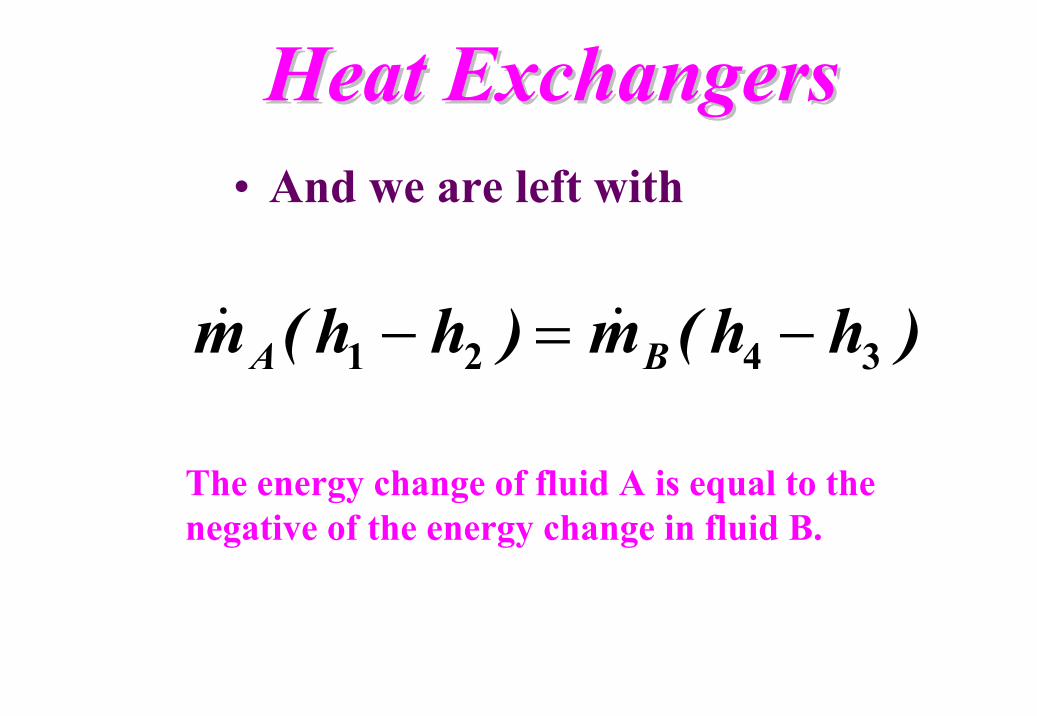
Heat ExchangersHeat Exchangers• And we are left with
)hh(m)hh(m BA 3421 −=− &&
The energy change of fluid A is equal to the negative of the energy change in fluid B.
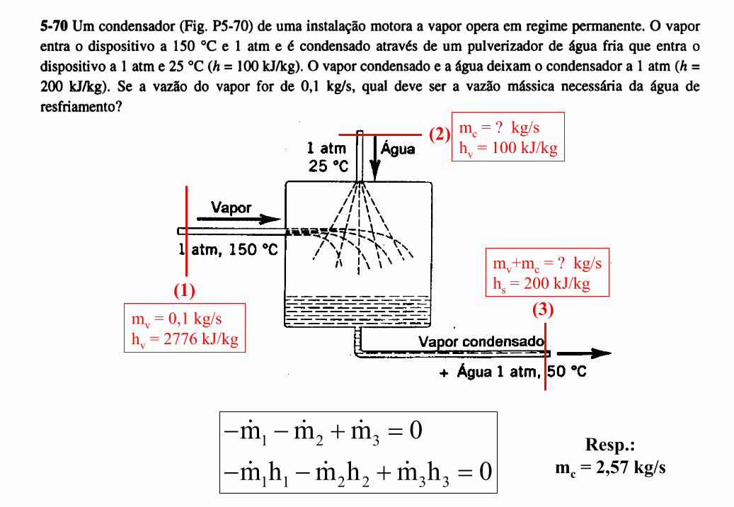
(1)(3)
(2)
mv = 0,1 kg/shv = 2776 kJ/kg
mc = ? kg/shv = 100 kJ/kg
mv+mc = ? kg/shs = 200 kJ/kg
1 2 3
1 1 2 2 3 3
m m m 0m h m h m h 0
− − + =
− − + =Resp.:
mc = 2,57 kg/s
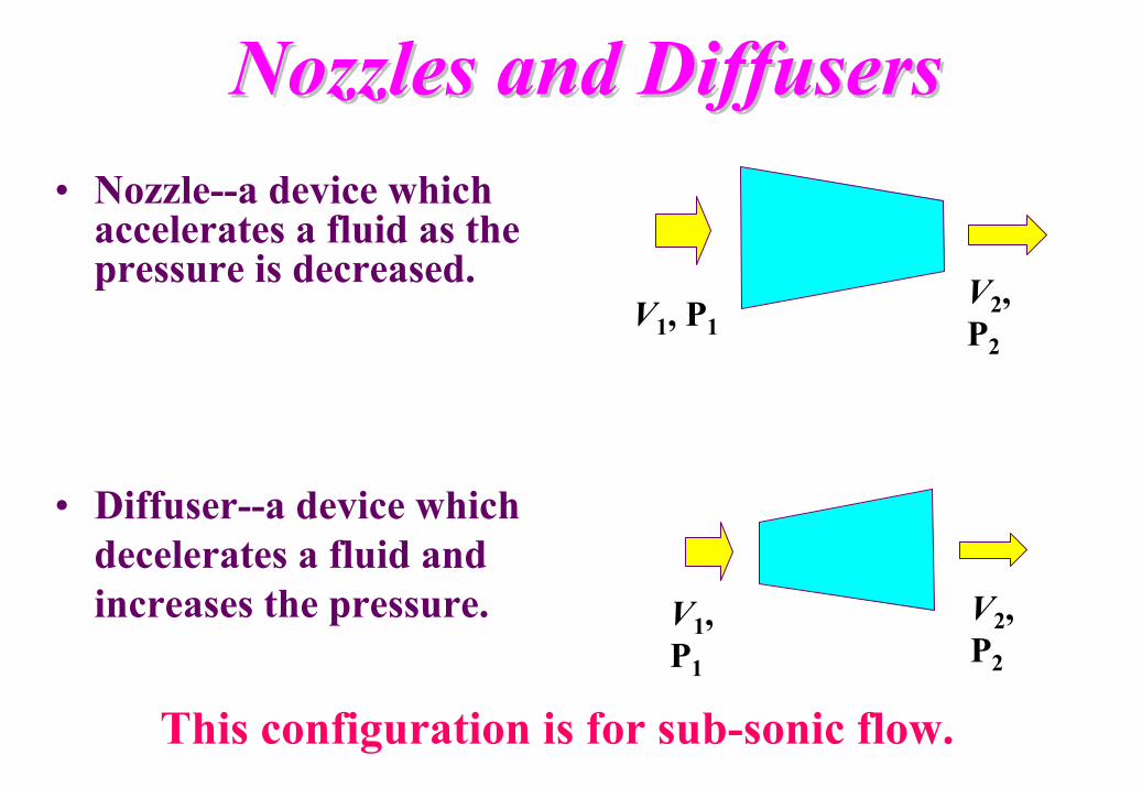
Nozzles and DiffusersNozzles and Diffusers• Nozzle--a device which
accelerates a fluid as the pressure is decreased.
This configuration is for sub-sonic flow.
V1, P1V2, P2
• Diffuser--a device which decelerates a fluid and increases the pressure. V1,
P1
V2, P2
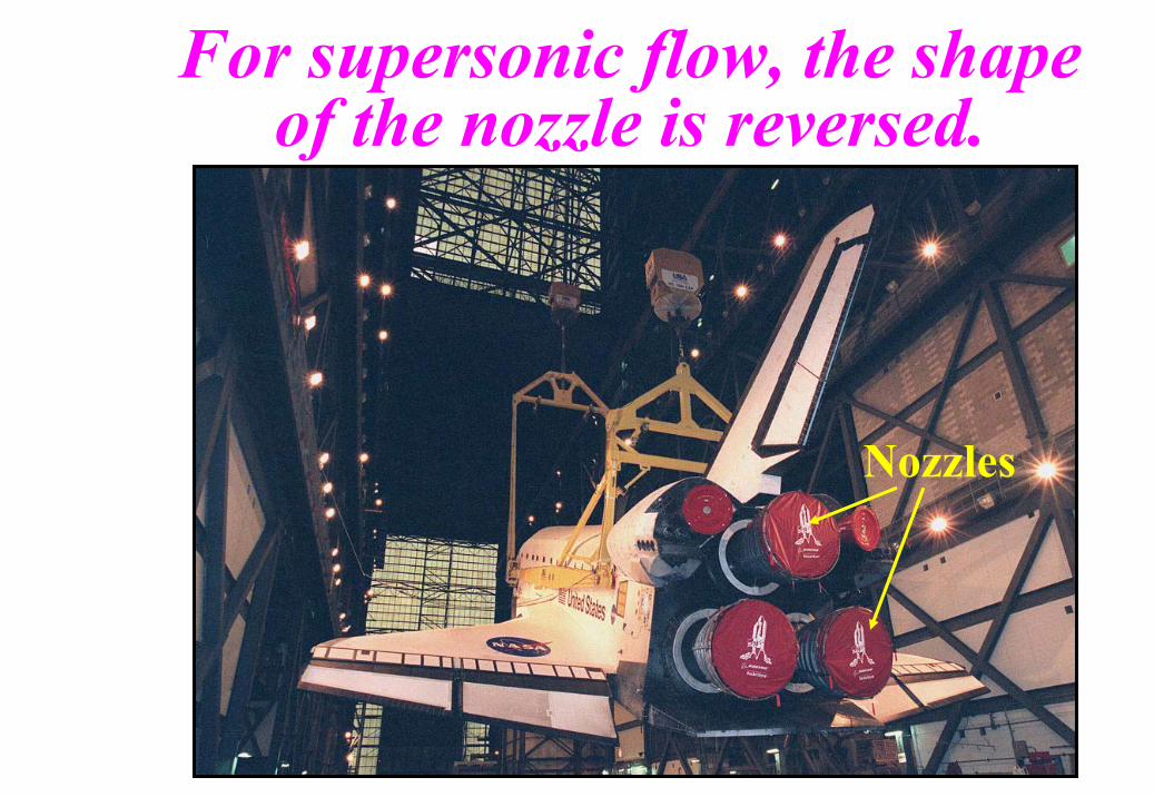
Nozzles
For supersonic flow, the shape of the nozzle is reversed.
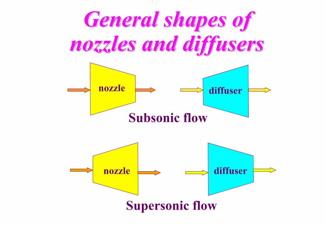
General shapes of General shapes of nozzles and diffusersnozzles and diffusers
Supersonic flow
Subsonic flow
nozzle diffuser
nozzle diffuser
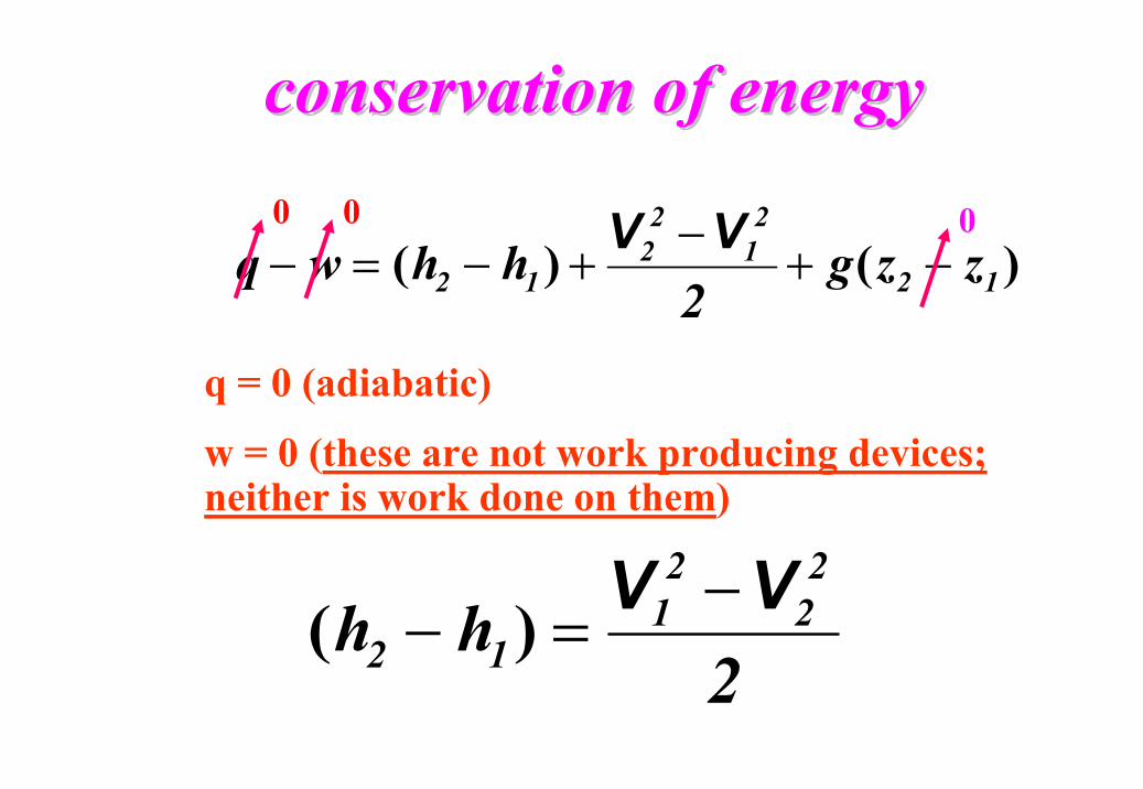
conservation of energyconservation of energy
q = 0 (adiabatic)
w = 0 (these are not work producing devices; neither is work done on them)
)()( 12
21
22
12 zzg2
hhwq −+−
+−=−VV0 0 0
2hh
22
21
12VV −
=− )(
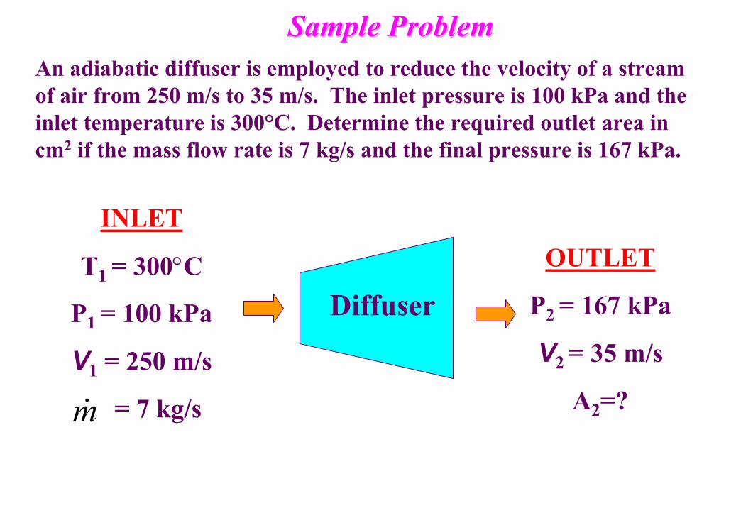
Sample ProblemSample ProblemAn adiabatic diffuser is employed to reduce the velocity of a stream of air from 250 m/s to 35 m/s. The inlet pressure is 100 kPa and the inlet temperature is 300°C. Determine the required outlet area in cm2 if the mass flow rate is 7 kg/s and the final pressure is 167 kPa.
OUTLET
P2 = 167 kPa
V2 = 35 m/s
A2=?
Diffuser
INLET
T1 = 300°C
P1 = 100 kPa
V1 = 250 m/s
= 7 kg/sm&
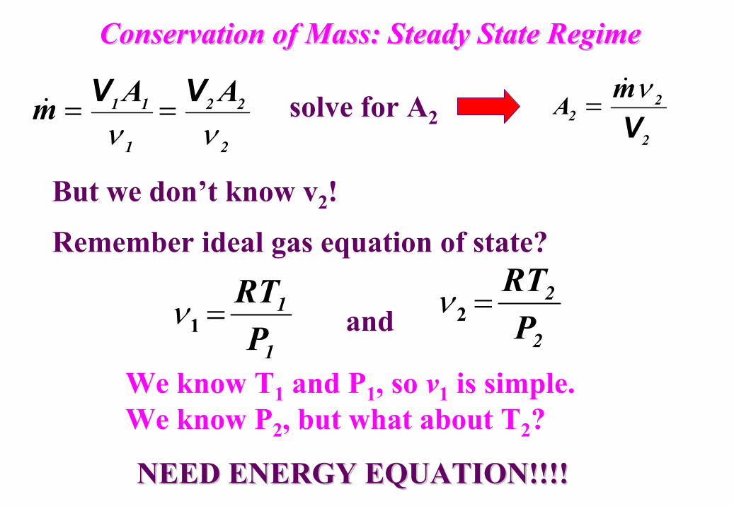
Conservation of Mass: Steady State RegimeConservation of Mass: Steady State Regime
2
22
1
11 AAmνν
VV ==& solve for A22
22
mA
Vν&=
But we don’t know v2!
Remember ideal gas equation of state?
1
1
PRT
=1ν2
2
PRT
=2νand
We know T1 and P1, so v1 is simple. We know P2, but what about T2?
NEED ENERGY EQUATION!!!!NEED ENERGY EQUATION!!!!
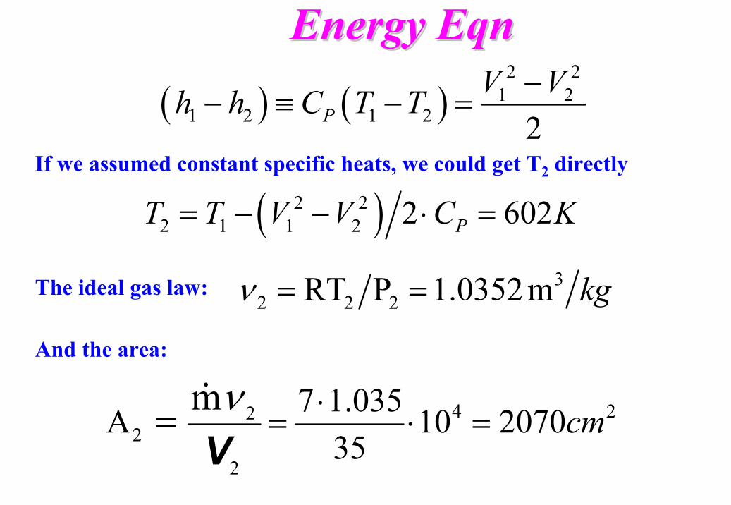
Energy Energy EqnEqn
If we assumed constant specific heats, we could get T2 directly
( ) ( )2 2
1 21 2 1 2 2P
V Vh h C T T −− ≡ − =
( )2 22 1 1 2 2 602PT T V V C K= − − ⋅ =
32 2 2RT P 1.0352m kgν = =The ideal gas law:
4 222
2
7 1.035A 10 207035
mcm
ν ⋅= ⋅ ==
&
V
And the area:
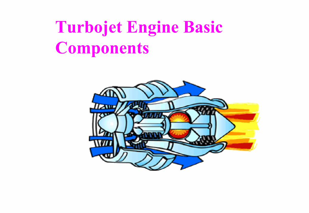
Turbojet Engine Basic Components
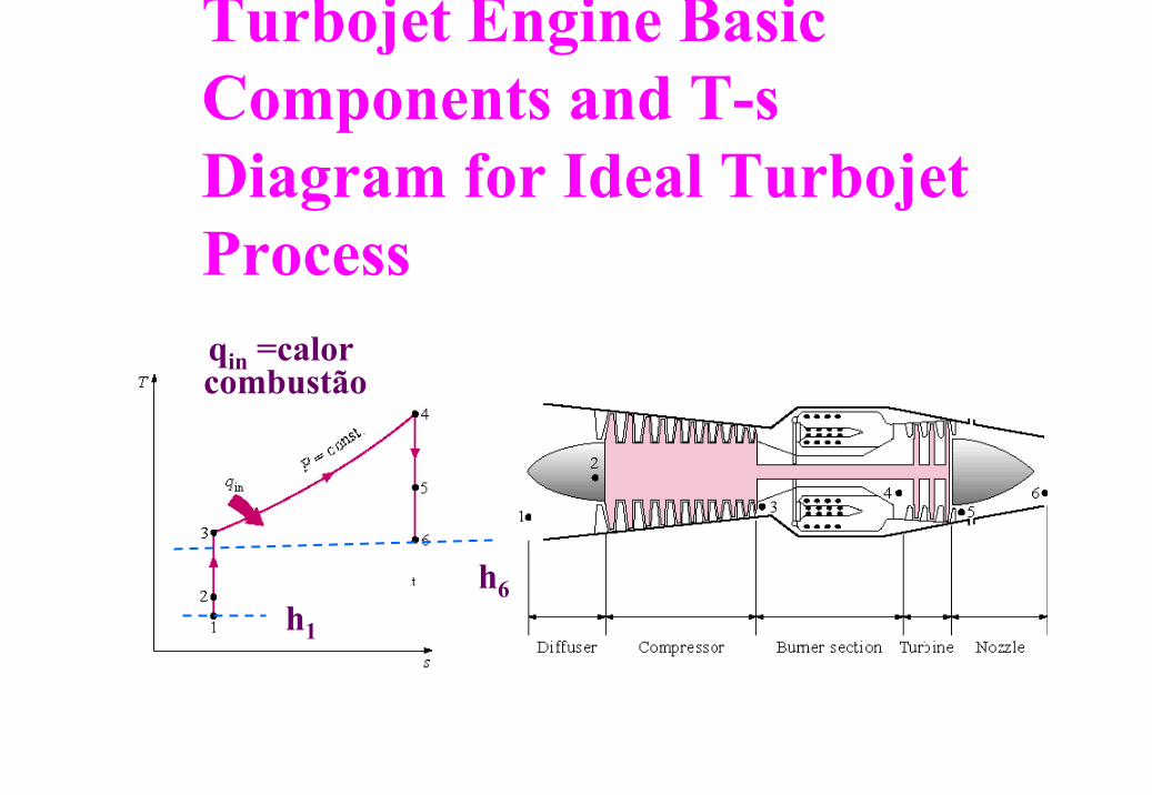
Turbojet Engine Basic Components and T-s Diagram for Ideal Turbojet Processqin =calor combustão
h6h1
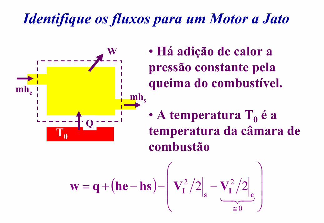
Identifique os fluxos para um Motor a Jato
mhe mhs
Q
W
T0
• Há adição de calor a pressão constante pela queima do combustível.
• A temperatura T0 é a temperatura da câmara de combustão
( )
−−−+=
≅321
0
22 22
eIsI VVhsheqw
Top Related