


γλώσσες
Σελίδες
Νομικός

1
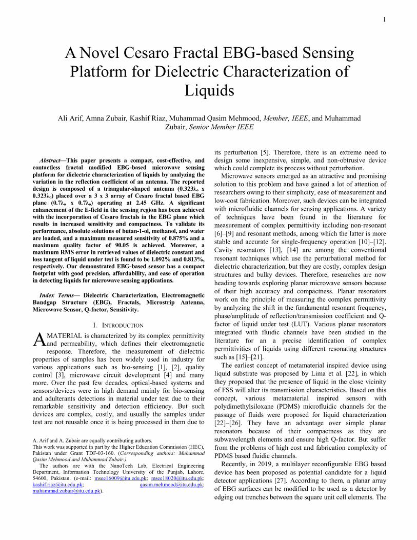
Abstract—This paper presents a compact, cost-effective, and
contactless fractal modified EBG-based microwave sensing platform for dielectric characterization of liquids by analyzing the variation in the reflection coefficient of an antenna. The reported design is composed of a triangular-shaped antenna (0.323λo x 0.323λo) placed over a 3 x 3 array of Cesaro fractal based EBG plane (0.7λo x 0.7λo) operating at 2.45 GHz. A significant enhancement of the E-field in the sensing region has been achieved with the incorporation of Cesaro fractals in the EBG plane which results in increased sensitivity and compactness. To validate its performance, absolute solutions of butan-1-ol, methanol, and water are loaded, and a maximum measured sensitivity of 0.875% and a maximum quality factor of 90.05 is achieved. Moreover, a maximum RMS error in retrieved values of dielectric constant and loss tangent of liquid under test is found to be 1.092% and 0.813%, respectively. Our demonstrated EBG-based sensor has a compact footprint with good precision, affordability, and ease of operation in detecting liquids for microwave sensing applications.
Index Terms— Dielectric Characterization, Electromagnetic Bandgap Structure (EBG), Fractals, Microstrip Antenna, Microwave Sensor, Q-factor, Sensitivity.
I. INTRODUCTION MATERIAL is characterized by its complex permittivity and permeability, which defines their electromagnetic response. Therefore, the measurement of dielectric
properties of samples has been widely used in industry for various applications such as bio-sensing [1], [2], quality control [3], microwave circuit development [4] and many more. Over the past few decades, optical-based systems and sensors/devices were in high demand mainly for bio-sensing and adulterants detections in material under test due to their remarkable sensitivity and detection efficiency. But such devices are complex, costly, and usually the samples under test are not reusable once it is being processed in them due to
A. Arif and A. Zubair are equally contributing authors. This work was supported in part by the Higher Education Commission (HEC), Pakistan under Grant TDF-03-160. (Corresponding authors: Muhammad Qasim Mehmood and Muhammad Zubair.)
The authors are with the NanoTech Lab, Electrical Engineering Department, Information Technology University of the Punjab, Lahore, 54600, Pakistan. (e-mail: [email protected]; [email protected]; [email protected]; [email protected]; [email protected]).
its perturbation [5]. Therefore, there is an extreme need to design some inexpensive, simple, and non-obtrusive device which could complete its process without perturbation.
Microwave sensors emerged as an attractive and promising solution to this problem and have gained a lot of attention of researchers owing to their simplicity, ease of measurement and low-cost fabrication. Moreover, such devices can be integrated with microfluidic channels for sensing applications. A variety of techniques have been found in the literature for measurement of complex permittivity including non-resonant [6]–[9] and resonant methods, among which the latter is more stable and accurate for single-frequency operation [10]–[12]. Cavity resonators [13], [14] are among the conventional resonant techniques which use the perturbational method for dielectric characterization, but they are costly, complex design structures and bulky devices. Therefore, researches are now heading towards exploring planar microwave sensors because of their high accuracy and compactness. Planar resonators work on the principle of measuring the complex permittivity by analyzing the shift in the fundamental resonant frequency, phase/amplitude of reflection/transmission coefficient and Q-factor of liquid under test (LUT). Various planar resonators integrated with fluidic channels have been studied in the literature for an a precise identification of complex permittivities of liquids using different resonating structures such as [15]–[21].
The earliest concept of metamaterial inspired device using liquid substrate was proposed by Lima et al. [22], in which they proposed that the presence of liquid in the close vicinity of FSS will alter its transmission characteristics. Based on this concept, various metamaterial inspired sensors with polydimethylsiloxane (PDMS) microfluidic channels for the passage of fluids were proposed for liquid characterization [22]–[26]. They have an advantage over simple planar resonators because of their compactness as they are subwavelength elements and ensure high Q-factor. But suffer from the problems of high cost and fabrication complexity of PDMS based fluidic channels.
Recently, in 2019, a multilayer reconfigurable EBG based device has been proposed as potential candidate for a liquid detector applications [27]. According to them, a planar array of EBG surfaces can be modified to be used as a detector by edging out trenches between the square unit cell elements. The
A Novel Cesaro Fractal EBG-based Sensing Platform for Dielectric Characterization of
Liquids Ali Arif, Amna Zubair, Kashif Riaz, Muhammad Qasim Mehmood, Member, IEEE, and Muhammad
Zubair, Senior Member IEEE
A
2
deposition of liquids having different dielectric properties in these trenches will produce a change in the reflection phase of EBG plane, which could be detected by using an antenna as a radiating source above EBG surface. This change in the phase of the surface waves characteristics of EBG plane produces a variation in the reflection coefficient of an antenna, which could be utilized for the detection of different liquids under test. Low-quality factor due to the usage of broadband CPW antenna, large footprint, the low detection range of dielectric properties for the LUT (1 to 21) and lack of sensitivity analysis are the major drawbacks of their proposed design and make it less feasible to be used as a practical liquid sensor.
TABLE I COMPARISON OF PROPOSED DESIGN WITH REPORTED EBG-BASED SENSING
PLATFORM AT 2.45 GHZ
Quantities Ref [27] Proposed Design
Size (L x W) 111 mm x 111 mm 82 mm x 82 mm
No. of Fluidic Channels 4 2
Nature of Fluidic Channels Liquid in Contact with device Contactless
Detection Range of εr 1 to 21.3 1 to 78
Max. Measured Q-Factor of LUT 22.71 90.05
Max. Measured Sensitivity of LUT (%) 0.858 0.875
Max. Percentage Error in Retrieval of εr of LUT N.A. 1.092
Max. Percentage Error in Retrieval of tanδ of LUT N.A. 0.813
In this work, we proposed a cost-effective, contactless, and
novel Cesaro fractal based compact EBG design to be used as a microwave sensing platform for measuring the complex permittivity of various liquids. Owing to the self-similar spatial distribution property of fractal geometries these structures are readily utilized in antenna engineering to design a compact and low-profile surfaces such as EBG plane, metamaterials, small antennas, etc [28], [29]. The proposed design is composed of 3 x 3 array of modified EBG plane using Cesaro fractals and an optimized triangular-shaped patch antenna [30] designed at 2.45 GHz, are presented and analyzed along with their working principle in detail in Section II. All the designing and analysis of the proposed device is carried out using a full-wave electromagnetic simulation solver of CST Microwave Studio software [31]. Section III focuses on the numerical and the experimental performance evaluation of our proposed sensing platform by loading the fluidic channels with LUT (butan-1-ol, methanol, and water). For the deposition of liquid, a simple, cost-effective and contactless solution comprising of Polypropylene (PP) channels is implemented. Upon loading the device with LUT, a substantial frequency shift in the reflection coefficient of patch antenna is detected because of the change in surface wave characteristic of EBG. Based on these shifted parameters, an accurate numerical model is formulated for calculation of complex permittivity along with
sensitivity and Q-factor analysis of LUT. Finally, a conclusion of the presented work is given in Section IV. Table I summarizes the performance analysis of the reported EBG detector and the proposed sensor. It is evident from the results that the incorporation of specialized Cesaro fractals in EBG plane has significantly improved its detection performance with contactless sensing nature and relatively compact footprints as compared to the reported design.
The detailed performance analysis of our proposed sensor suggests that it is a good candidate for an inexpensive, low-profile and contactless sensing applications of liquids without compromising its accuracy and sensitivity. To the best knowledge of authors, this is the first design based on the Cesaro fractal modified EBG structure for dielectric characterization of liquids.
II. DETECTOR DESIGN AND CONFIGURATION
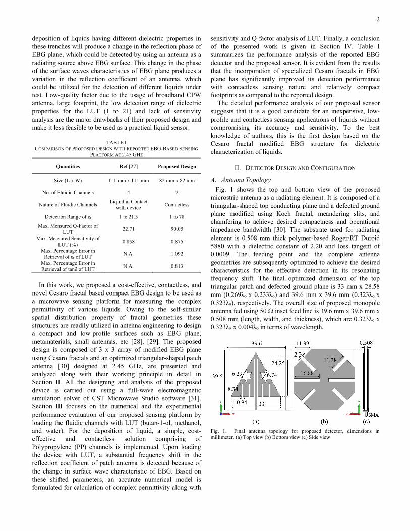
A. Antenna Topology Fig. 1 shows the top and bottom view of the proposed
microstrip antenna as a radiating element. It is composed of a triangular-shaped top conducting plane and a defected ground plane modified using Koch fractal, meandering slits, and chamfering to achieve desired compactness and operational impedance bandwidth [30]. The substrate used for radiating element is 0.508 mm thick polymer-based Roger/RT Duroid 5880 with a dielectric constant of 2.20 and loss tangent of 0.0009. The feeding point and the complete antenna geometries are subsequently optimized to achieve the desired characteristics for the effective detection in its resonating frequency shift. The final optimized dimension of the top triangular patch and defected ground plane is 33 mm x 28.58 mm (0.269λo x 0.233λo) and 39.6 mm x 39.6 mm (0.323λo x 0.323λo), respectively. The overall size of proposed monopole antenna fed using 50 Ω inset feed line is 39.6 mm x 39.6 mm x 0.508 mm (length, width, and thickness), which are 0.323λo x 0.323λo x 0.004λo in terms of wavelength.
Fig. 1. Final antenna topology for proposed detector, dimensions in millimeter. (a) Top view (b) Bottom view (c) Side view
3
B. EBG Design Initially, a square-shaped unit cell is considered as the EBG
plane underneath the radiator for the effective detection of a shift in the resonant frequency of an antenna. Here, EBG plane is preferred our a Perfect Electric Conductor (PEC) surface because PEC surfaces exhibit deconstructive interference between the transmitted and reflected signals when placed in the close proximity of an antenna; and they exhibit constructive interference when placed at a distance of λo/4 which is significantly a large dimension for a low-profile device [32], [33].
The detailed analysis of a reflection phase characteristics of a unit cell is done to propose a suitable EBG design for the chosen application. For its design and optimization, the reflection phase characterization method proposed by Yahya Rahmat-Samii et al. is used [34]. According to them, the input-match frequency band of an EBG is very close to the range of frequencies having a reflection phase of 90o ± 45o. This input-match frequency band is a range of frequencies in which the EBG surfaces neither behave like a PEC plane nor like a PMC plane having a reflection phase of 180o or 0o, respectively, for a normally incident plane wave. Instead, this exhibits a band of frequencies having a good return loss of an antenna.
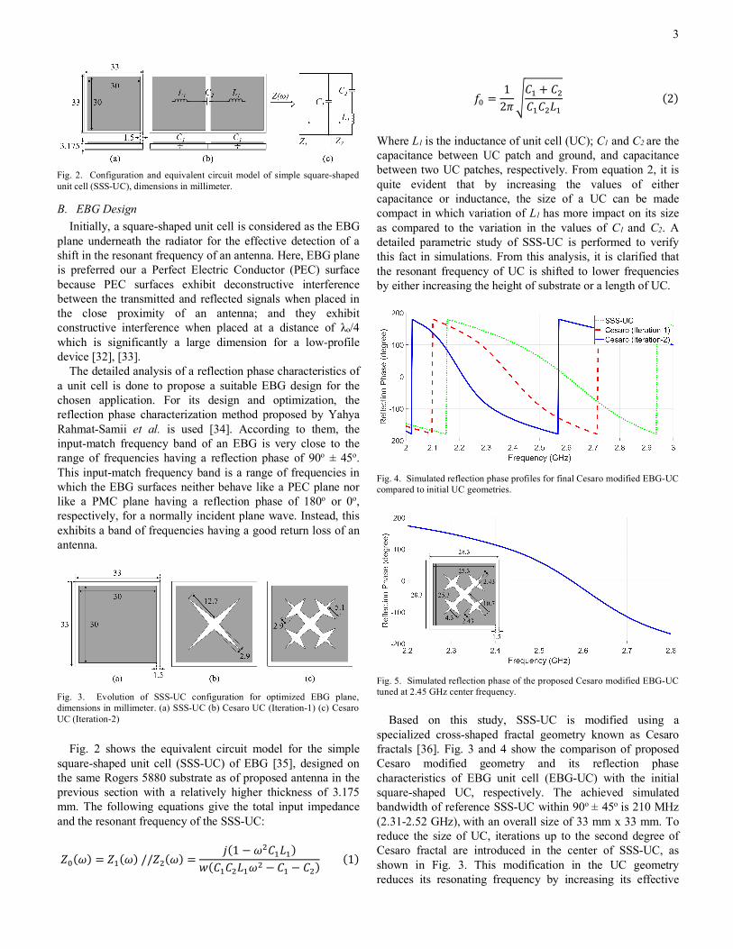
Fig. 2 shows the equivalent circuit model for the simple
square-shaped unit cell (SSS-UC) of EBG [35], designed on the same Rogers 5880 substrate as of proposed antenna in the previous section with a relatively higher thickness of 3.175 mm. The following equations give the total input impedance and the resonant frequency of the SSS-UC:
𝑍"(𝜔) = 𝑍'(𝜔)//𝑍*(𝜔) =𝑗(1 − 𝜔*𝐶'𝐿')
𝑤(𝐶'𝐶*𝐿'𝜔* − 𝐶' − 𝐶*)(1)
𝑓" =12𝜋4𝐶' + 𝐶*𝐶'𝐶*𝐿'
(2)
Where L1 is the inductance of unit cell (UC); C1 and C2 are the capacitance between UC patch and ground, and capacitance between two UC patches, respectively. From equation 2, it is quite evident that by increasing the values of either capacitance or inductance, the size of a UC can be made compact in which variation of L1 has more impact on its size as compared to the variation in the values of C1 and C2. A detailed parametric study of SSS-UC is performed to verify this fact in simulations. From this analysis, it is clarified that the resonant frequency of UC is shifted to lower frequencies by either increasing the height of substrate or a length of UC.
Based on this study, SSS-UC is modified using a
specialized cross-shaped fractal geometry known as Cesaro fractals [36]. Fig. 3 and 4 show the comparison of proposed Cesaro modified geometry and its reflection phase characteristics of EBG unit cell (EBG-UC) with the initial square-shaped UC, respectively. The achieved simulated bandwidth of reference SSS-UC within 90o ± 45o is 210 MHz (2.31-2.52 GHz), with an overall size of 33 mm x 33 mm. To reduce the size of UC, iterations up to the second degree of Cesaro fractal are introduced in the center of SSS-UC, as shown in Fig. 3. This modification in the UC geometry reduces its resonating frequency by increasing its effective
Fig. 4. Simulated reflection phase profiles for final Cesaro modified EBG-UC compared to initial UC geometries.
Fig. 2. Configuration and equivalent circuit model of simple square-shaped unit cell (SSS-UC), dimensions in millimeter.
Fig. 5. Simulated reflection phase of the proposed Cesaro modified EBG-UC tuned at 2.45 GHz center frequency.
Fig. 3. Evolution of SSS-UC configuration for optimized EBG plane, dimensions in millimeter. (a) SSS-UC (b) Cesaro UC (Iteration-1) (c) Cesaro UC (Iteration-2)
4
electrical length and thus results in its compactness [37]. It is clear from Fig. 4 that the 90o reflection phase point of the proposed EBG-UC is scaled down by a factor of 12.3% as compared to the initial square-shaped EBG-UC. Fig. 5 shows the reflection phase of the proposed EBG-UC tuned at 2.45 GHz and its final optimized geometry is shown in the inset of Fig. 5. The achieved bandwidth of final EBG-UC design within 90o ± 45o is 180 MHz (2.34-2.52 GHz), with an overall size of 28.3 mm x 28.3 mm.
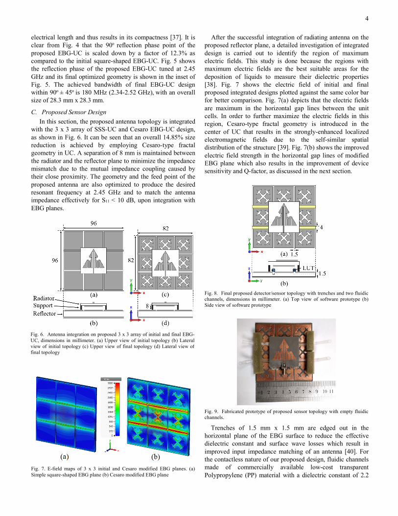
C. Proposed Sensor Design In this section, the proposed antenna topology is integrated
with the 3 x 3 array of SSS-UC and Cesaro EBG-UC design, as shown in Fig. 6. It can be seen that an overall 14.85% size reduction is achieved by employing Cesaro-type fractal geometry in UC. A separation of 8 mm is maintained between the radiator and the reflector plane to minimize the impedance mismatch due to the mutual impedance coupling caused by their close proximity. The geometry and the feed point of the proposed antenna are also optimized to produce the desired resonant frequency at 2.45 GHz and to match the antenna impedance effectively for S11 < 10 dB, upon integration with EBG planes.
After the successful integration of radiating antenna on the proposed reflector plane, a detailed investigation of integrated design is carried out to identify the region of maximum electric fields. This study is done because the regions with maximum electric fields are the best suitable areas for the deposition of liquids to measure their dielectric properties [38]. Fig. 7 shows the electric field of initial and final proposed integrated designs plotted against the same color bar for better comparison. Fig. 7(a) depicts that the electric fields are maximum in the horizontal gap lines between the unit cells. In order to further maximize the electric fields in this region, Cesaro-type fractal geometry is introduced in the center of UC that results in the strongly-enhanced localized electromagnetic fields due to the self-similar spatial distribution of the structure [39]. Fig. 7(b) shows the improved electric field strength in the horizontal gap lines of modified EBG plane which also results in the improvement of device sensitivity and Q-factor, as discussed in the next section.
Trenches of 1.5 mm x 1.5 mm are edged out in the horizontal plane of the EBG surface to reduce the effective dielectric constant and surface wave losses which result in improved input impedance matching of an antenna [40]. For the contactless nature of our proposed design, fluidic channels made of commercially available low-cost transparent Polypropylene (PP) material with a dielectric constant of 2.2
Fig. 9. Fabricated prototype of proposed sensor topology with empty fluidic channels.
Fig. 8. Final proposed detector/sensor topology with trenches and two fluidic channels, dimensions in millimeter. (a) Top view of software prototype (b) Side view of software prototype
Fig. 7. E-field maps of 3 x 3 initial and Cesaro modified EBG planes. (a) Simple square-shaped EBG plane (b) Cesaro modified EBG plane
Fig. 6. Antenna integration on proposed 3 x 3 array of initial and final EBG-UC, dimensions in millimeter. (a) Upper view of initial topology (b) Lateral view of initial topology (c) Upper view of final topology (d) Lateral view of final topology
5
and a diameter of 4 mm are introduced on the strongly-enhanced electromagnetic field regions for deposition of LUT, as shown in Fig. 8.
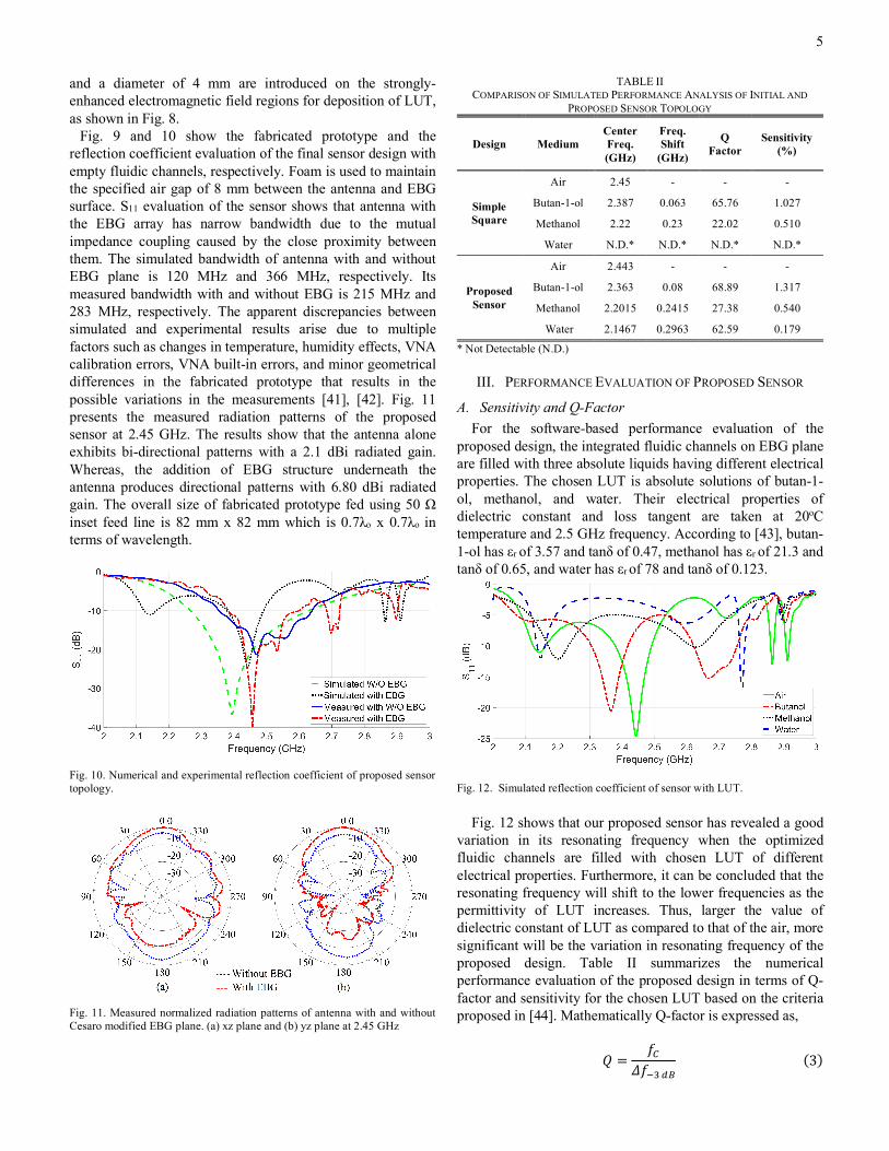
Fig. 9 and 10 show the fabricated prototype and the reflection coefficient evaluation of the final sensor design with empty fluidic channels, respectively. Foam is used to maintain the specified air gap of 8 mm between the antenna and EBG surface. S11 evaluation of the sensor shows that antenna with the EBG array has narrow bandwidth due to the mutual impedance coupling caused by the close proximity between them. The simulated bandwidth of antenna with and without EBG plane is 120 MHz and 366 MHz, respectively. Its measured bandwidth with and without EBG is 215 MHz and 283 MHz, respectively. The apparent discrepancies between simulated and experimental results arise due to multiple factors such as changes in temperature, humidity effects, VNA calibration errors, VNA built-in errors, and minor geometrical differences in the fabricated prototype that results in the possible variations in the measurements [41], [42]. Fig. 11 presents the measured radiation patterns of the proposed sensor at 2.45 GHz. The results show that the antenna alone exhibits bi-directional patterns with a 2.1 dBi radiated gain. Whereas, the addition of EBG structure underneath the antenna produces directional patterns with 6.80 dBi radiated gain. The overall size of fabricated prototype fed using 50 Ω inset feed line is 82 mm x 82 mm which is 0.7λo x 0.7λo in terms of wavelength.
TABLE II COMPARISON OF SIMULATED PERFORMANCE ANALYSIS OF INITIAL AND
PROPOSED SENSOR TOPOLOGY
Design Medium Center Freq. (GHz)
Freq. Shift
(GHz)
Q Factor
Sensitivity (%)
Simple Square
Air 2.45 - - -
Butan-1-ol 2.387 0.063 65.76 1.027
Methanol 2.22 0.23 22.02 0.510
Water N.D.* N.D.* N.D.* N.D.*
Proposed Sensor
Air 2.443 - - -
Butan-1-ol 2.363 0.08 68.89 1.317
Methanol 2.2015 0.2415 27.38 0.540
Water 2.1467 0.2963 62.59 0.179
* Not Detectable (N.D.)
III. PERFORMANCE EVALUATION OF PROPOSED SENSOR
A. Sensitivity and Q-Factor For the software-based performance evaluation of the
proposed design, the integrated fluidic channels on EBG plane are filled with three absolute liquids having different electrical properties. The chosen LUT is absolute solutions of butan-1-ol, methanol, and water. Their electrical properties of dielectric constant and loss tangent are taken at 20oC temperature and 2.5 GHz frequency. According to [43], butan-1-ol has εr of 3.57 and tanδ of 0.47, methanol has εr of 21.3 and tanδ of 0.65, and water has εr of 78 and tanδ of 0.123.
Fig. 12 shows that our proposed sensor has revealed a good
variation in its resonating frequency when the optimized fluidic channels are filled with chosen LUT of different electrical properties. Furthermore, it can be concluded that the resonating frequency will shift to the lower frequencies as the permittivity of LUT increases. Thus, larger the value of dielectric constant of LUT as compared to that of the air, more significant will be the variation in resonating frequency of the proposed design. Table II summarizes the numerical performance evaluation of the proposed design in terms of Q-factor and sensitivity for the chosen LUT based on the criteria proposed in [44]. Mathematically Q-factor is expressed as,
𝑄 =𝑓7
𝛥𝑓9:;<(3)
Fig. 10. Numerical and experimental reflection coefficient of proposed sensor topology.
Fig. 11. Measured normalized radiation patterns of antenna with and without Cesaro modified EBG plane. (a) xz plane and (b) yz plane at 2.45 GHz
Fig. 12. Simulated reflection coefficient of sensor with LUT.
6
Here, fc and Δf-3dB are the center/resonating frequency and 3 dB frequency bandwidth, respectively. According to the proposed criteria, the sensitivity of the detector is mathematically expressed as,
𝑆 =𝛥𝑓 𝑓?⁄𝛥𝜀 (4)
Where, Δf is defined as ‘(fo - fs)’ and Δε is expressed as ‘εs - εo’. For sensitivity estimation of the device, empty channels filled with air are considered as a reference, and its permittivity and resonating frequency are expressed as εo and fo, respectively, whereas εs and fs are the dielectric constant and resonating frequency of channels filled with LUT. From this analysis, it is clear that we have achieved improved Q-factor and sensitivity for a proposed design using specialized Cesaro fractal EBG plane as compared to a simple square-shaped EBG surface. For theoretical validation, consider the following expression for Q-factor of a resonating patch [45]:
𝑄 = 2𝜋𝑓C𝑊E +𝑊F
𝑃HC??(5)
Here, fo is the resonating frequency, and Ploss is the dissipated power. We and Wm are the average stored electric and magnetic energies, respectively and given as:
𝑊𝑒+𝑊𝑚 =12 𝜀|𝐸C|* +
12 𝜇|𝐻C|*(6)
Where, Eo and Ho are the electric and magnetic field intensities of the unloaded device, respectively. According to [39], [46], the effective incorporation of fractal geometry in the conducting surfaces enhances its EM fields and improves its concentration in the gaps, as shown in Fig. 7, which increases energy being stored in the EBG surface. Moreover, from equation 5, it is clear that the increase in the stored energy will increase the quality factor of the overall device. Thus, the sensor topology with modified Cesaro fractal-based EBG structure has a higher Q-factor as compared to the simple square-shaped EBG, as depicted in Table II. Furthermore, according to the resonant perturbation theory [47], the resonance frequency shift (Δf) due to the LUT and the sensitivity of a device follow the equation as mentioned below:
𝛥𝑓𝑓C≈ −
∭ (𝛥𝜇|𝐻C|* + 𝛥𝜀|𝐸C|*) 𝑑𝑣U
∭ (𝜇|𝐻C|* + 𝜀|𝐸C|*)𝑑𝑣U (7)
Where, Δε and Δµ denote the relative change of permittivity and permeability, respectively. For simple and modified UC, keeping all the other parameters constants, the intensity of electromagnetic fields (Eo and Ho) for modified UC is higher as compared to the simple square-shaped UC as mentioned in the previous section. Therefore, from equation 7, it is clear that higher the intensities of EM wave higher will be the shift
in the operating frequency. And from equation 4, it is quite evident that the sensitivity of the device is directly related to this frequency shift, which results in higher sensitivity of modified sensor design compared to its initial design, as reported in Table II. Also, the detection span of the proposed sensor is improved, and it has successfully detected the shift in its resonating frequency when the channels are filled with water as LUT having the highest permittivity of 78 among others.
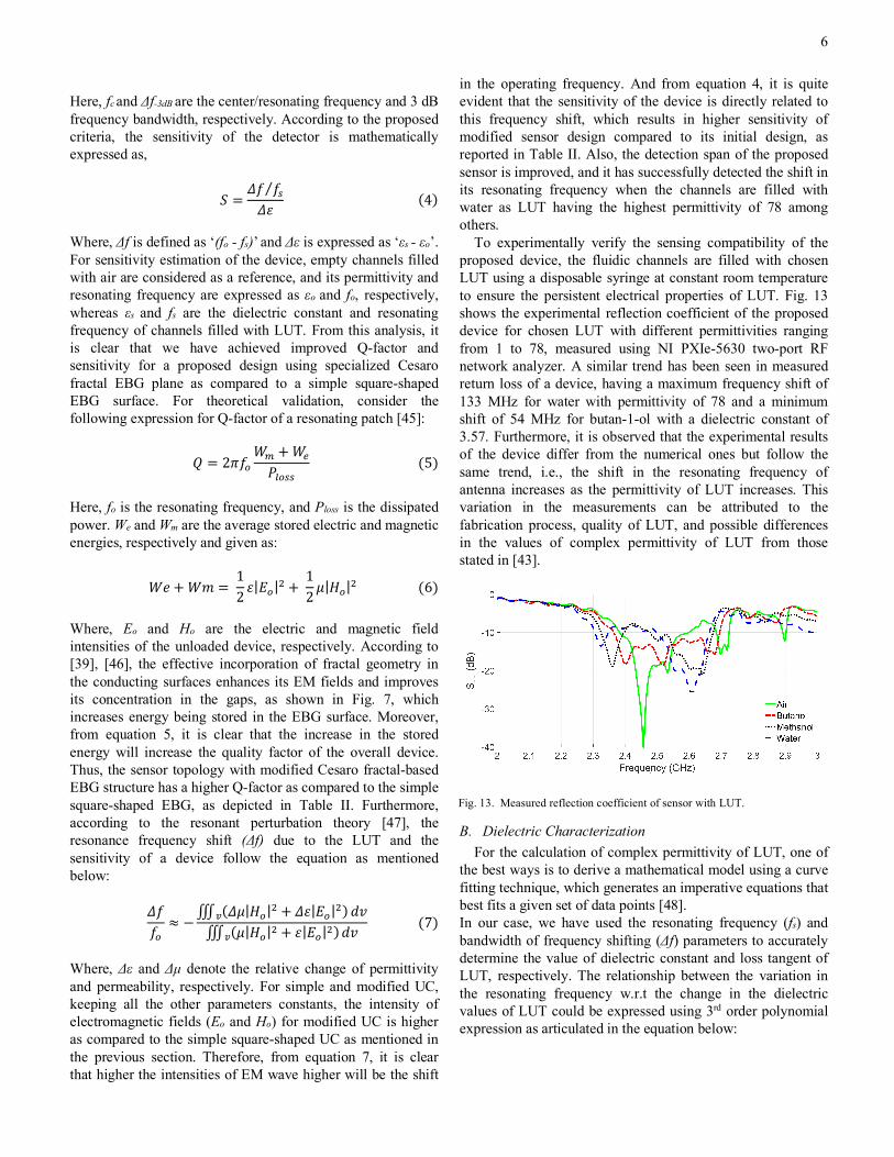
To experimentally verify the sensing compatibility of the proposed device, the fluidic channels are filled with chosen LUT using a disposable syringe at constant room temperature to ensure the persistent electrical properties of LUT. Fig. 13 shows the experimental reflection coefficient of the proposed device for chosen LUT with different permittivities ranging from 1 to 78, measured using NI PXIe-5630 two-port RF network analyzer. A similar trend has been seen in measured return loss of a device, having a maximum frequency shift of 133 MHz for water with permittivity of 78 and a minimum shift of 54 MHz for butan-1-ol with a dielectric constant of 3.57. Furthermore, it is observed that the experimental results of the device differ from the numerical ones but follow the same trend, i.e., the shift in the resonating frequency of antenna increases as the permittivity of LUT increases. This variation in the measurements can be attributed to the fabrication process, quality of LUT, and possible differences in the values of complex permittivity of LUT from those stated in [43].
B. Dielectric Characterization For the calculation of complex permittivity of LUT, one of
the best ways is to derive a mathematical model using a curve fitting technique, which generates an imperative equations that best fits a given set of data points [48]. In our case, we have used the resonating frequency (fs) and bandwidth of frequency shifting (Δf) parameters to accurately determine the value of dielectric constant and loss tangent of LUT, respectively. The relationship between the variation in the resonating frequency w.r.t the change in the dielectric values of LUT could be expressed using 3rd order polynomial expression as articulated in the equation below:
Fig. 13. Measured reflection coefficient of sensor with LUT.
7
𝜀W = 10Y × (−8.239𝑓?: + 59.83𝑓?* − 144.847𝑓?+ 116.882)(8)
Where εr is the real value of calculated permittivity, and fs is the resonating frequency of LUT. The relationship between the bandwidth of frequency shifting and loss tangent is mathematically expressed using 3rd degree polynomial equation as the best-fitting graph to produce an accurate numerical model as expressed in
𝑡𝑎𝑛𝛿 = −237.52𝛥𝑓* + 40.02𝛥𝑓 − 0.9986(9) Where tanδ is the calculated value of loss tangent, and Δf is the bandwidth of resonating frequency for chosen LUT.
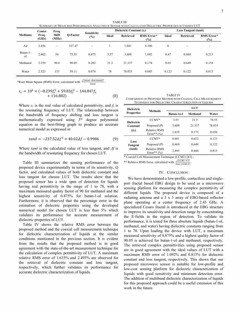
Table III summarizes the sensing performance of the proposed device experimentally in terms of its sensitivity, Q factor, and calculated values of both dielectric constant and loss tangent for chosen LUT. The results show that the proposed sensor has a wide span of detection for liquids having real permittivity in the range of 1 to 78, with a maximum measured quality factor of 90 for methanol and the highest sensitivity of 0.875% for butan-1-ol solution. Furthermore, it is observed that the percentage error in the estimation of dielectric properties using the developed numerical model for chosen LUT is less than 5% which validates its performance for accurate measurement of dielectric properties of LUT.
Table IV shows the relative RMS error between the proposed method and the coaxial cell measurement technique for dielectric characterization of liquids at the similar conditions mentioned in the previous section. It is evident from the results that the proposed method is in good agreement with the state-of-the-art measurement technique for the calculation of complex permittivity of LUT. A maximum relative RMS error of 1.635% and 2.495% are observed for the retrieval of dielectric constant and loss tangent, respectively, which further validates its performance for accurate dielectric characterization of liquids.
TABLE IV
COMPARISON OF PROPOSED METHOD WITH COAXIAL CELL MEASUREMENT TECHNIQUE FOR DIELECTRIC CHARACTERIZATION OF LIQUIDS
Dielectric Properties Methods
LUT
Butan-1o-l Methanol Water
Dielectric Constant
(εr)
CCMT* 3.55 21.3 78.55
Proposed (P) 3.609 21.337 78.035 Relative RMS Error** (%) 1.635 0.173 0.656
Loss Tangent (tanδ)
CCMT* 0.481 0.652 0.123
Proposed (P) 0.469 0.649 0.122 Relative RMS Error** (%) 2.495 0.460 0.813
* Coaxial Cell Measurement Technique (CCMT) [43] ;
** Relative RMS Error, calculated with b(77cd9e)f
Egh(77cd,e) .
IV. CONCLUSION We have demonstrated a low-profile, contactless and single-
port fractal based EBG design to be used as a microwave sensing platform for measuring the complex permittivity of different liquids. The proposed device is composed of a radiating antenna and a 3 x 3 array of EBG-based reflector plane operating at a center frequency of 2.45 GHz. A specialized Cesaro fractal is introduced in the EBG structure to improve its sensitivity and detection range by concentrating the E-fields in the region of detection. To validate its performance, it is tested for three absolute liquids (butan-1-ol, methanol, and water) having dielectric constants ranging from 1 to 78. Upon loading the device with LUT, a maximum measured sensitivity of 0.875% and a highest quality factor of 90.05 is achieved for butan-1-ol and methanol, respectively. The retrieved complex permittivities using proposed sensor are in good agreement with the ideal values of LUT with a maximum RMS error of 1.092% and 0.813% for dielectric constant and loss tangent, respectively. This shows that our proposed microwave sensor is suitable for low-profile and low-cost sensing platform for dielectric characterization of liquids with good sensitivity and minimum detection error. The addition of multiband dielectric characterization of liquids for this proposed approach could be a useful extension of this work in the future.
*Root Mean Square (RMS) Error, calculated with b(j;FgH9kFlWmFUF;)f
j;FgH .
TABLE III SUMMARY OF MEASURED PERFORMANCE ANALYSIS OF SENSOR WITH CALCULATED DIELECTRIC PROPERTIES OF CHOSEN LUT
Mediums Center Freq. (GHz)
Freq. Shift
(MHz) Q-Factor Sensitivity
(%)
Dielectric Constant (εr) Loss Tangent (tanδ)
Ideal Retrieved RMS Error* (%)
Ideal Retrieved RMS Error* (%)
Air 2.456 - 327.47 - 1 1.041 4.100 0 - -
Butan-1-ol 2.402 54 75.55 0.875 3.57 3.609 1.092 0.47 0.469 0.213
Methanol 2.359 96.8 90.05 0.202 21.3 21.337 0.174 0.65 0.649 0.154
Water 2.323 133 59.11 0.074 78 78.035 0.045 0.123 0.122 0.813
8
REFERENCES
[1] K. Grenier et al., “Integrated broadband microwave and microfluidic sensor dedicated to bioengineering,” IEEE Trans. Microw. Theory Tech., vol. 57, no. 12, pp. 3246–3253, 2009.
[2] A. Tamra, D. Dubuc, M. P. Rols, and K. Grenier, “Microwave Monitoring of Single Cell Monocytes Subjected to Electroporation,” IEEE Trans. Microw. Theory Tech., vol. 65, no. 9, pp. 3512–3518, 2017.
[3] T. K. Kataria, J. L. Olvera-Cervantes, A. Corona-Chávez, R. Rojas-Laguna, and M. E. Sosa-Morales, “Dielectric properties of guava, mamey sapote, prickly pears, and Nopal in the microwave range,” Int. J. Food Prop., vol. 20, no. 12, pp. 2944–2953, 2017.
[4] G. Ghione and M. Pirola, Microwave electronics. 2017. [5] R. A. Awang, F. J. Tovar-Lopez, T. Baum, S. Sriram, and W. S. T.
Rowe, “Meta-atom microfluidic sensor for measurement of dielectric properties of liquids,” J. Appl. Phys., vol. 121, no. 9, 2017.
[6] A. Nyshadham, C. L. Sibbald, and S. S. Stuchly, “Permittivity Measurements using Open-Ended Sensors and Reference Liquid Calibration—an Uncertainty Analysis,” IEEE Trans. Microw. Theory Tech., vol. 40, no. 2, pp. 305–314, 1992.
[7] U. Kaatze and Y. Feldman, “Broadband dielectric spectrometry of liquids and biosystems,” Meas. Sci. Technol., vol. 17, no. 2, 2006.
[8] P. M. Narayanan, “Microstrip transmission line method for broadband permittivity measurement of dielectric substrates,” IEEE Trans. Microw. Theory Tech., vol. 62, no. 11, pp. 2784–2790, 2014.
[9] Z. Akhter and M. J. Akhtar, “Free-Space Time Domain Position Insensitive Technique for Simultaneous Measurement of Complex Permittivity and Thickness of Lossy Dielectric Samples,” IEEE Trans. Instrum. Meas., vol. 65, no. 10, pp. 2394–2405, 2016.
[10] Y. Kato and M. Horibe, “New permittivity measurement methods using resonant phenomena for high-permittivity materials,” IEEE Trans. Instrum. Meas., vol. 66, no. 6, pp. 1191–1200, 2017.
[11] H. Hamzah, J. Lees, and A. Porch, “Split ring resonator with optimised sensitivity for microfluidic sensing,” Sensors Actuators, A Phys., vol. 276, pp. 1–10, 2018.
[12] E. Piuzzi, E. Pittella, S. Pisa, A. Cataldo, E. De Benedetto, and G. Cannazza, “Microwave reflectometric methodologies for water content estimation in stone-made Cultural Heritage materials,” Meas. J. Int. Meas. Confed., vol. 118, pp. 275–281, 2018.
[13] A. K. Jha and M. J. Akhtar, “A generalized rectangular cavity approach for determination of complex permittivity of materials,” IEEE Trans. Instrum. Meas., vol. 63, no. 11, pp. 2632–2641, 2014.
[14] A. H. Sklavounos and N. S. Barker, “Liquid-permittivity measurements using a rigorously modeled overmoded cavity resonator,” IEEE Trans. Microw. Theory Tech., vol. 62, no. 6, pp. 1363–1372, 2014.
[15] E. L. Chuma, Y. Iano, G. Fontgalland, and L. L. Bravo Roger, “Microwave sensor for liquid dielectric characterization based on metamaterial complementary split ring resonator,” IEEE Sens. J., vol. 18, no. 24, pp. 9978–9983, 2018.
[16] C.-S. Lee, B. Bai, Q.-R. Song, Z. Wang, and G.-F. Li, “Open Complementary Split-Ring Resonator Sensor for Dropping-Based Liquid Dielectric Characterization,” IEEE Sens. J., vol. PP, no. c, pp. 1–1, 2019.
[17] F. S. Jafari and J. Ahmadi-Shokouh, “Reconfigurable microwave SIW sensor based on PBG structure for high accuracy permittivity
characterization of industrial liquids,” Sensors Actuators, A Phys., vol. 283, pp. 386–395, 2018.
[18] D. J. Rowe, S. Al-Malki, A. A. Abduljabar, A. Porch, D. A. Barrow, and C. J. Allender, “Improved split-ring resonator for microfluidic sensing,” IEEE Trans. Microw. Theory Tech., vol. 62, no. 3, pp. 689–699, 2014.
[19] P. Velez, L. Su, K. Grenier, J. Mata-Contreras, D. Dubuc, and F. Martin, “Microwave Microfluidic Sensor Based on a Microstrip Splitter/Combiner Configuration and Split Ring Resonators (SRRs) for Dielectric Characterization of Liquids,” IEEE Sens. J., vol. 17, no. 20, pp. 6589–6598, 2017.
[20] A. A. Abduljabar, N. Clark, J. Lees, and A. Porch, “Dual Mode Microwave Microfluidic Sensor for Temperature Variant Liquid Characterization,” IEEE Trans. Microw. Theory Tech., vol. 65, no. 7, pp. 2572–2582, 2017.
[21] A. Ebrahimi, J. Scott, and K. Ghorbani, “Microwave reflective biosensor for glucose level detection in aqueous solutions,” Sensors Actuators, A Phys., vol. 301, p. 111662, 2020.
[22] A. C. D. E. C. Lima, E. A. Parker, and R. J. Langley, “Tunable frequency selective surface using liquid substrates,” Electron. Lett., vol. 30, no. 4, pp. 281–282, 1994.
[23] R. Yadav and P. N. Patel, “Experimental Study of Adulteration Detection in Fish Oil Using Novel PDMS Cavity Bonded EBG Inspired Patch Sensor,” IEEE Sens. J., vol. 16, no. 11, pp. 4354–4361, 2016.
[24] A. Ebrahimi, W. Withayachumnankul, S. Al-Sarawi, and D. Abbott, “High-sensitivity metamaterial-inspired sensor for microfluidic dielectric characterization,” IEEE Sens. J., vol. 14, no. 5, pp. 1345–1351, 2014.
[25] M. Labidi, J. B. Tahar, and F. Choubani, “Meta-materials applications in thin- film sensing and sensing liquids properties,” Opt. Express, vol. 19, no. S4, p. A733, 2011.
[26] W. Liu, H. Sun, and L. Xu, “A microwave method for dielectric characterization measurement of small liquids using a metamaterial-based sensor,” Sensors (Switzerland), vol. 18, no. 5, 2018.
[27] S. Y. Jun, B. Sanz Izquierdo, and E. A. Parker, “Liquid Sensor/Detector Using an EBG Structure,” IEEE Trans. Antennas Propag., vol. 67, no. 5, pp. 3366–3373, 2019.
[28] D. H. Werner and S. Ganguly, “An overview of fractal antenna engineering research,” IEEE Antennas Propag. Mag., vol. 45, no. 1, pp. 38–57, Feb. 2003.
[29] W. J. K. E.-F. Brambila, “Fractals in Antennas and Metamaterials Applications,” Rijeka: IntechOpen, 2017, p. Ch. 3.
[30] A. Arif, M. Zubair, M. Ali, M. U. Khan, and M. Q. Mehmood, “A Compact, Low-Profile Fractal Antenna for Wearable On-Body WBAN Applications,” IEEE Antennas Wirel. Propag. Lett., vol. 18, no. 5, pp. 981–985, 2019.
[31] “CST Microwave Studio.” [Online]. Available: http://www.cst.com. [32] H. Khaleel, Innovation in Wearable and Flexible Antennas. Wit
Press, 2014. [33] F. Yang and Y. Rahmat-Samii, Electromagnetic Band Gap
Structures in Antenna Engineering. Cambridge University Press, 2009.
[34] F. Yang and Y. Rahmat-Samii, “Reflection Phase Characterizations of the EBG Ground Plane for Low Profile Wire Antenna Applications,” IEEE Trans. Antennas Propag., vol. 51, no. 10 I, pp. 2691–2703, 2003.
9
[35] X. Liu, Y. Di, H. Liu, Z. Wu, and M. M. Tentzeris, “A Planar Windmill-Like Broadband Antenna Equipped with Artificial Magnetic Conductor for Off-Body Communications,” IEEE Antennas Wirel. Propag. Lett., vol. 15, pp. 64–67, 2016.
[36] P. L. Michael Batty, “Fractal-Cities-BATTY-LONGLEY-1994.pdf.” p. 432, 1994.
[37] W. J. Krzysztofik, “Fractal geometry in electromagnetics applications - from antenna to metamaterials,” Microw. Rev., vol. 19, no. 2, pp. 3–14, 2013.
[38] A. A. Abduljabar, D. J. Rowe, A. Porch, and D. A. Barrow, “Novel microwave microfluidic sensor using a microstrip split-ring resonator,” IEEE Trans. Microw. Theory Tech., vol. 62, no. 3, pp. 679–688, 2014.
[39] E. Aslan et al., “Multispectral Cesaro-Type Fractal Plasmonic Nanoantennas,” ACS Photonics, vol. 3, no. 11, pp. 2102–2111, 2016.
[40] S. B. Yeap and Z. N. Chen, “Microstrip patch antennas with enhanced gain by partial substrate removal,” IEEE Trans. Antennas Propag., vol. 58, no. 9, pp. 2811–2816, 2010.
[41] U. Kingdom and A. Service, “The Expression of Uncertainty and Confidence in Measurement,” Measurement, vol. 44, no. January, pp. 21–47, 2007.
[42] G. A. E. Vandenbosch, “State-of-the-art in antenna software benchmarking: ‘are we there yet ?’ [euraap corner],” IEEE Antennas Propag. Mag., vol. 56, no. 4, pp. 300–308, Aug. 2014.
[43] A. P. Gregory and R. N. Clarke, “Tables of the Complex Permittivity of Dielectric Reference Liquids at Frequencies up to 5 GHz; NPL Report MAT 23,” Innovation, no. March, pp. 1–87, 2009.
[44] H. Lobato-Morales, D. V. B. Murthy, A. Corona-Chávez, J. L. Olvera-Cervantes, J. Martínez-Brito, and L. G. Guerrero-Ojeda, “Permittivity measurements at microwave frequencies using epsilon-near-zero (ENZ) tunnel structure,” IEEE Trans. Microw. Theory Tech., vol. 59, no. 7, pp. 1863–1868, 2011.
[45] D. M. Pozar, Microwave Engineering, 4th Edition. Wiley, 2011. [46] S. Cakmakyapan, N. A. Cinel, A. O. Cakmak, and E. Ozbay,
“Validation of electromagnetic field enhancement in near-infrared through Sierpinski fractal nanoantennas,” Opt. Express, vol. 22, no. 16, p. 19504, 2014.
[47] B. Meng, J. Booske, and R. Cooper, “Extended cavity perturbation technique to determine the complex permittivity of dielectric materials,” IEEE Trans. Microw. Theory Tech., vol. 43, no. 11, pp. 2633–2636, 1995.
[48] A. A. Mohd Bahar, Z. Zakaria, M. K. Md. Arshad, A. A. M. Isa, Y. Dasril, and R. A. Alahnomi, “Real Time Microwave Biochemical Sensor Based on Circular SIW Approach for Aqueous Dielectric Detection,” Sci. Rep., vol. 9, no. 1, pp. 1–12, 2019.
Ali Arif received his BS (2016) in Electrical Engineering from the University of Central Punjab Lahore with the highest distinction and MS (2018) in Electrical Engineering from Information Technology University Lahore where he is currently associated as a Research Associate. His research interests are in the field of applied electromagnetics related to wearable and conformal antennas, Electromagnetic Band Gap (EBG) structures, and sensors for remote health monitoring systems.
Amna Zubair has completed her BS in Electrical Engineering (2017) from the College of Electrical and Mechanical Engineering, NUST Islamabad, and MS (2020) in Electrical Engineering from Information Technology University Lahore, where she is currently associated as a Research Associate. Her research focus includes RF system design, microwave imaging, antenna design, and investigations of novel phenomena because
of EM wave interaction with Fractal 2D metamaterials.
Kashif Riaz is an Assistant Professor in Electrical Engineering department of Information Technology University (ITU), Lahore, Pakistan. He did his PhD (2016) from Hong Kong University of Science and Technology (HKUST). His current research interests are on design, modelling, simulation and characterization of nano-structures for biological manipulations, and micro/ nanoelectromechanical systems using multidisciplinary approaches to develop innovative solutions for
biomedical and healthcare applications.
Muhammad Qasim Mehmood is an Assistant Professor in Electrical Engineering department of Information Technology University (ITU), Lahore, Pakistan. He received his PhD (2016) in Electrical and Computer Engineering from National University of Singapore. His research interests are in the area of RF and microwave engineering, optics and nano-photonics; more precisely the demonstration of exotic phenomena via ultra-thin
nano-structured devices, e.g., on-chip orbital angular manipulation, beam-steering, spin-orbital coupling, holography, polarization filtering and light absorption etc.
Muhammad Zubair (S’13–M’15–SM’20) received the Ph.D. degree in electronic engineering from the Politecnico di Torino, Italy, in 2015. From 2015 to 2017, he was with the SUTD-MIT International Design Center, Singapore. Since 2017, he has been with Information Technology University, Lahore, Pakistan, as an Assistant Professor. His current research interests include applied and computational electromagnetics, fractal
electrodynamics, electron device modeling, and microwave imaging.
Top Related