


γλώσσες
Σελίδες
Νομικός

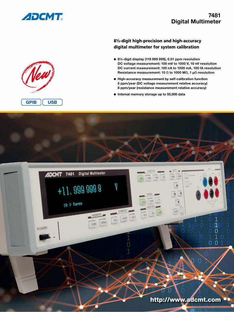
7481Digital Multimeter
http://www.adcmt.com
8½-digit high-precision and high-accuracydigital multimeter for system calibration
l 8½-digit display (119 999 999), 0.01 ppm resolution DC voltage measurement: 100 mV to 1000 V, 10 nV resolution DC current measurement: 100 nA to 1000 mA, 100 fA resolution Resistance measurement: 10 Ω to 1000 MΩ, 1 μΩ resolution
l High-accuracy measurement by self-calibration function 5 ppm/year (DC voltage measurement relative accuracy) 8 ppm/year (resistance measurement relative accuracy)
l Internal memory storage up to 50,000 data
8½ digits high precision for high accuracy proofreading systems2
The 7481 is an 8½-digit digital multimeter with high reso-lution of 0.01 ppm, equipped with DC voltage, DC current and resistance measurement functions. It is suitable for use in research and development fields or calibration organiza-tions, and calibration of inspection systems for electronic components or semiconductors.The 7481 achieves high-resolution measurement such as 10 nV for DC voltage measurement, 100 fA for DC current measurement and 1 μΩ for resistance measurement, and
also guarantees high relative accuracy 5 ppm per year for voltage measurement.In addition, the self-calibration function allows high-accu-racy measurement at any time, and external calibration can be performed with a smaller number of standards.The 7481 has not only the GPIB and the USB as interface for automatic systems but also input terminals on the rear panel for easy system configuration
Voltage measurement
l 5 ranges: 0.1 V to 1000 Vl Resolution from 4½ digits to 8½
digitsl Minimum resolution 10 nVl Stabilized voltage relative accuracy
5 ppm/year
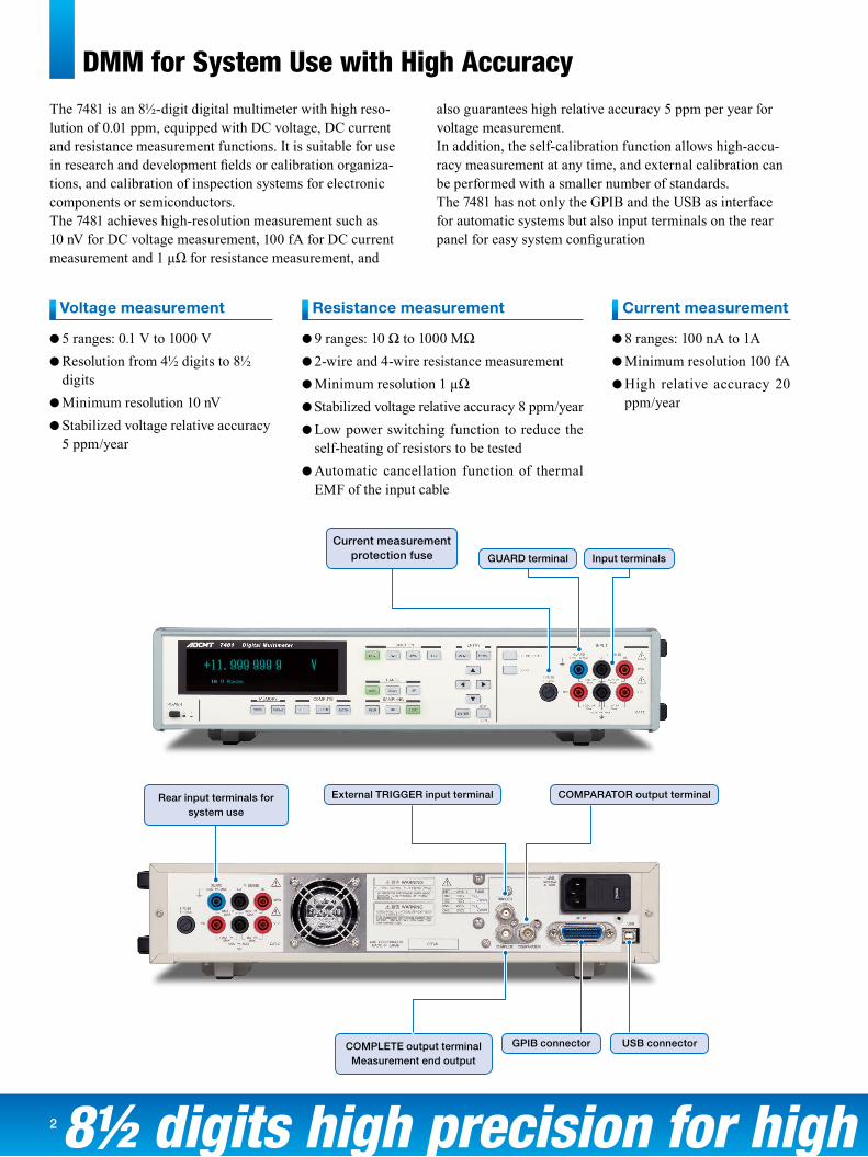
Current measurement protection fuse
External TRIGGER input terminal COMPARATOR output terminal
GUARD terminal Input terminals
Rear input terminals for system use
COMPLETE output terminalMeasurement end output
USB connectorGPIB connector
DMM for System Use with High Accuracy
Resistance measurement
l 9 ranges: 10 Ω to 1000 MΩl 2-wire and 4-wire resistance measurementl Minimum resolution 1 µΩl Stabilized voltage relative accuracy 8 ppm/yearl Low power switching function to reduce the
self-heating of resistors to be testedl Automatic cancellation function of thermal
EMF of the input cable
Current measurement
l 8 ranges: 100 nA to 1Al Minimum resolution 100 fAl High relative accuracy 20
ppm/year
8½ digits high precision for high accuracy proofreading systems 3
200
1.00
0.10
0.01
0.01 0.1 10 1001
Integration time (PLC)
100 mV range display dispersion (typical value)
Input 0V
Dis
pla
y d
isp
ersi
on (μ
Vrm
s)200
180
160
140
120
100
80
60
40
20
0
-0.04
-0.03
-0.02
-0.01 0
0.010.02
0.030.04
Stability (ppm)
Co
un
t
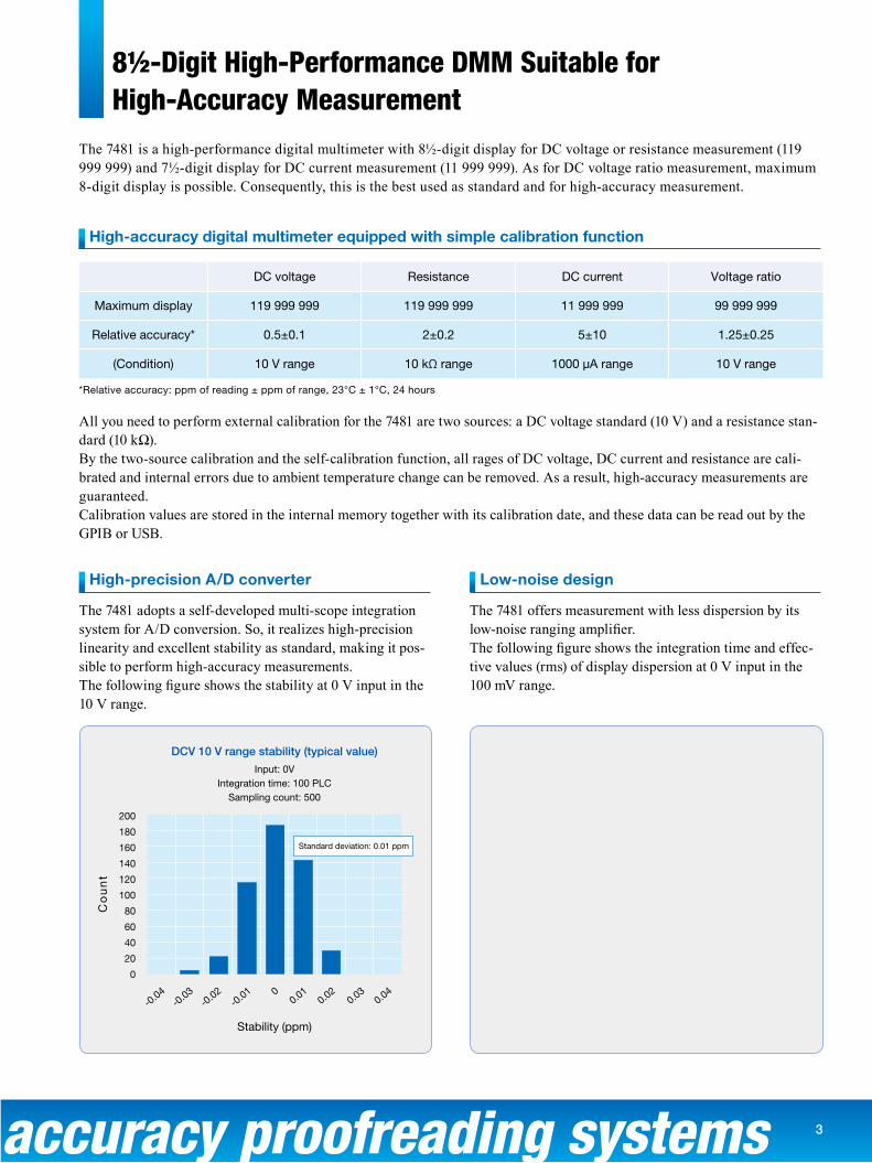
DCV 10 V range stability (typical value)
Input: 0VIntegration time: 100 PLC
Sampling count: 500
Standard deviation: 0.01 ppm
The 7481 is a high-performance digital multimeter with 8½-digit display for DC voltage or resistance measurement (119 999 999) and 7½-digit display for DC current measurement (11 999 999). As for DC voltage ratio measurement, maximum 8-digit display is possible. Consequently, this is the best used as standard and for high-accuracy measurement.
*Relative accuracy: ppm of reading ± ppm of range, 23°C ± 1°C, 24 hours
DC voltage Resistance DC current Voltage ratio
Maximum display 119 999 999 119 999 999 11 999 999 99 999 999
Relative accuracy* 0.5±0.1 2±0.2 5±10 1.25±0.25
(Condition) 10 V range 10 kΩ range 1000 µA range 10 V range
High-accuracy digital multimeter equipped with simple calibration function
All you need to perform external calibration for the 7481 are two sources: a DC voltage standard (10 V) and a resistance stan-dard (10 kΩ).By the two-source calibration and the self-calibration function, all rages of DC voltage, DC current and resistance are cali-brated and internal errors due to ambient temperature change can be removed. As a result, high-accuracy measurements are guaranteed.Calibration values are stored in the internal memory together with its calibration date, and these data can be read out by the GPIB or USB.
Low-noise design
The 7481 offers measurement with less dispersion by its low-noise ranging amplifier.The following figure shows the integration time and effec-tive values (rms) of display dispersion at 0 V input in the 100 mV range.
High-precision A/D converter
The 7481 adopts a self-developed multi-scope integration system for A/D conversion. So, it realizes high-precision linearity and excellent stability as standard, making it pos-sible to perform high-accuracy measurements.The following figure shows the stability at 0 V input in the 10 V range.
8½-Digit High-Performance DMM Suitable for High-Accuracy Measurement
Wide Range & High Speed Measuring4
The 7481 has not only precise DC voltage measurement function but also high-precision resistance measurement function in which micro thermal electromotive force that causes errors in resistance measurement is cancelled automatically.
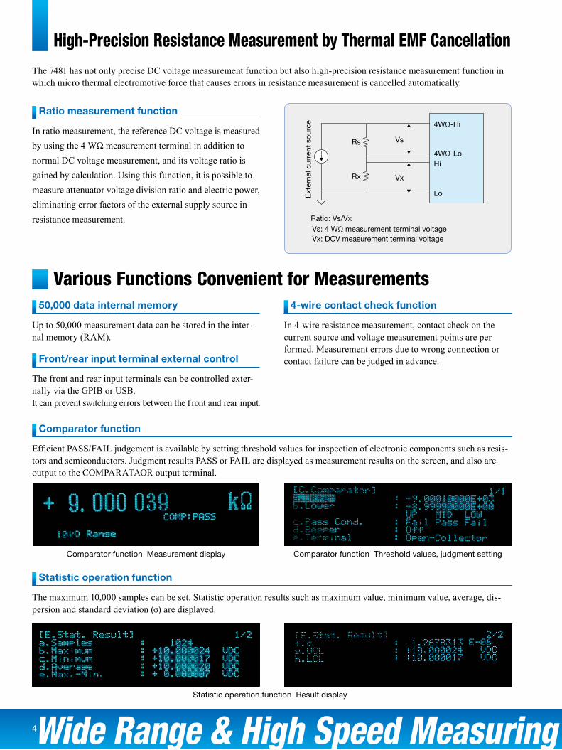
Ratio measurement function
In ratio measurement, the reference DC voltage is measured by using the 4 WΩ measurement terminal in addition to normal DC voltage measurement, and its voltage ratio is gained by calculation. Using this function, it is possible to measure attenuator voltage division ratio and electric power, eliminating error factors of the external supply source in resistance measurement.
Various Functions Convenient for Measurements50,000 data internal memory
Up to 50,000 measurement data can be stored in the inter-nal memory (RAM).
Front/rear input terminal external control
The front and rear input terminals can be controlled exter-nally via the GPIB or USB.It can prevent switching errors between the f ront and rear input.
4-wire contact check function
In 4-wire resistance measurement, contact check on the current source and voltage measurement points are per-formed. Measurement errors due to wrong connection or contact failure can be judged in advance.
Comparator function
Efficient PASS/FAIL judgement is available by setting threshold values for inspection of electronic components such as resis-tors and semiconductors. Judgment results PASS or FAIL are displayed as measurement results on the screen, and also are output to the COMPARATAOR output terminal.
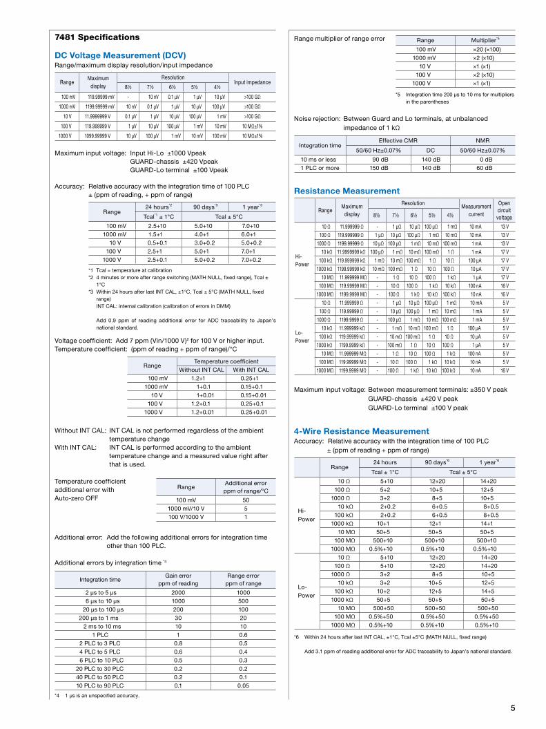
Statistic operation function
The maximum 10,000 samples can be set. Statistic operation results such as maximum value, minimum value, average, dis-persion and standard deviation (σ) are displayed.
Comparator function Measurement display
Statistic operation function Result display
Comparator function Threshold values, judgment setting
High-Precision Resistance Measurement by Thermal EMF Cancellation
Ext
erna
l cur
rent
sou
rce
Rs Vs
4WΩ-Hi
4WΩ-LoHi
Lo
VxRx
Ratio: Vs/VxVs: 4 WΩ measurement terminal voltageVx: DCV measurement terminal voltage
5
Range multiplier of range error
*5 Integration time 200 μs to 10 ms for multipliers in the parentheses
Noise rejection: Between Guard and Lo terminals, at unbalanced impedance of 1 kΩ
Resistance Measurement
Maximum input voltage: Between measurement terminals: ±350 V peak GUARD-chassis ±420 V peak GUARD-Lo terminal ±100 V peak
4-Wire Resistance MeasurementAccuracy: Relative accuracy with the integration time of 100 PLC ± (ppm of reading + ppm of range)
*6 Within 24 hours after last INT CAL, ±1°C, Tcal ±5°C (MATH NULL, fixed range)
Add 3.1 ppm of reading additional error for ADC traceability to Japan’s national standard.
7481 Specifications
DC Voltage Measurement (DCV)Range/maximum display resolution/input impedance
Maximum input voltage: Input Hi-Lo ±1000 Vpeak GUARD-chassis ±420 Vpeak GUARD-Lo terminal ±100 Vpeak
Accuracy: Relative accuracy with the integration time of 100 PLC ± (ppm of reading, + ppm of range)
*1 Tcal = temperature at calibration*2 4 minutes or more after range switching (MATH NULL, fixed range), Tcal ±
1°C*3 Within 24 hours after last INT CAL, ±1°C, Tcal ± 5°C (MATH NULL, fixed
range) INT CAL: internal calibration (calibration of errors in DMM)
Add 0.9 ppm of reading additional error for ADC traceability to Japan’s national standard.
Voltage coefficient: Add 7 ppm (Vin/1000 V)2 for 100 V or higher input.Temperature coefficient: (ppm of reading + ppm of range)/°C
Without INT CAL: INT CAL is not performed regardless of the ambient temperature change
With INT CAL: INT CAL is performed according to the ambient temperature change and a measured value right after that is used.
Temperature coefficient additional error with Auto-zero OFF
Additional error: Add the following additional errors for integration time other than 100 PLC.
Additional errors by integration time *4
*4 1 µs is an unspecified accuracy.
Range24 hours*2 90 days*3 1 year*3
Tcal*1 ± 1°C Tcal ± 5°C
100 mV 2.5+10 5.0+10 7.0+101000 mV 1.5+1 4.0+1 6.0+1
10 V 0.5+0.1 3.0+0.2 5.0+0.2100 V 2.5+1 5.0+1 7.0+1
1000 V 2.5+0.1 5.0+0.2 7.0+0.2
RangeAdditional errorppm of range/°C
100 mV 501000 mV/10 V 5100 V/1000 V 1
RangeTemperature coefficient
Without INT CAL With INT CAL100 mV 1.2+1 0.25+1
1000 mV 1+0.1 0.15+0.110 V 1+0.01 0.15+0.01
100 V 1.2+0.1 0.25+0.11000 V 1.2+0.01 0.25+0.01
RangeMaximum
display
ResolutionInput impedance
8½ 7½ 6½ 5½ 4½
100 mV 119.99999 mV - 10 nV 0.1 µV 1 µV 10 µV >100 GΩ
1000 mV 1199.99999 mV 10 nV 0.1 µV 1 µV 10 µV 100 µV >100 GΩ
10 V 11.9999999 V 0.1 µV 1 µV 10 µV 100 µV 1 mV >100 GΩ
100 V 119.999999 V 1 µV 10 µV 100 µV 1 mV 10 mV 10 MΩ±1%
1000 V 1099.99999 V 10 µV 100 µV 1 mV 10 mV 100 mV 10 MΩ±1%
Integration timeGain error
ppm of readingRange error
ppm of range
2 μs to 5 μs 2000 10006 μs to 10 μs 1000 500
20 μs to 100 μs 200 100200 μs to 1 ms 30 20
2 ms to 10 ms 10 101 PLC 1 0.6
2 PLC to 3 PLC 0.8 0.54 PLC to 5 PLC 0.6 0.46 PLC to 10 PLC 0.5 0.3
20 PLC to 30 PLC 0.2 0.240 PLC to 50 PLC 0.2 0.110 PLC to 90 PLC 0.1 0.05
Range Multiplier*5
100 mV ×20 (×100)1000 mV ×2 (×10)
10 V ×1 (×1)100 V ×2 (×10)
1000 V ×1 (×1)
Integration timeEffective CMR NMR
50/60 Hz±0.07% DC 50/60 Hz±0.07%
10 ms or less 90 dB 140 dB 0 dB1 PLC or more 150 dB 140 dB 60 dB
RangeMaximum
display
Resolution Measurement current
Open circuit voltage8½ 7½ 6½ 5½ 4½
Hi-Power
10 Ω 11.999999 Ω - 1 μΩ 10 μΩ 100 μΩ 1 mΩ 10 mA 13 V100 Ω 119.999999 Ω 1 μΩ 10 μΩ 100 μΩ 1 mΩ 10 mΩ 10 mA 13 V
1000 Ω 1199.99999 Ω 10 μΩ 100 μΩ 1 mΩ 10 mΩ 100 mΩ 1 mA 13 V10 kΩ 11.9999999 kΩ 100 μΩ 1 mΩ 10 mΩ 100 mΩ 1 Ω 1 mA 17 V
100 kΩ 119.999999 kΩ 1 mΩ 10 mΩ 100 mΩ 1 Ω 10 Ω 100 μA 17 V1000 kΩ 1199.99999 kΩ 10 mΩ 100 mΩ 1 Ω 10 Ω 100 Ω 10 μA 17 V
10 MΩ 11.999999 MΩ - 1 Ω 10 Ω 100 Ω 1 kΩ 1 μA 17 V100 MΩ 119.99999 MΩ - 10 Ω 100 Ω 1 kΩ 10 kΩ 100 nA 16 V
1000 MΩ 1199.9999 MΩ - 100 Ω 1 kΩ 10 kΩ 100 kΩ 10 nA 16 V
Lo-Power
10 Ω 11.999999 Ω - 1 μΩ 10 μΩ 100 μΩ 1 mΩ 10 mA 5 V100 Ω 119.99999 Ω - 10 μΩ 100 μΩ 1 mΩ 10 mΩ 1 mA 5 V
1000 Ω 1199.9999 Ω - 100 μΩ 1 mΩ 10 mΩ 100 mΩ 1 mA 5 V10 kΩ 11.999999 kΩ - 1 mΩ 10 mΩ 100 mΩ 1 Ω 100 μA 5 V
100 kΩ 119.99999 kΩ - 10 mΩ 100 mΩ 1 Ω 10 Ω 10 μA 5 V1000 kΩ 1199.9999 kΩ - 100 mΩ 1 Ω 10 Ω 100 Ω 1 μA 5 V
10 MΩ 11.999999 MΩ - 1 Ω 10 Ω 100 Ω 1 kΩ 100 nA 5 V100 MΩ 119.99999 MΩ - 10 Ω 100 Ω 1 kΩ 10 kΩ 10 nA 5 V
1000 MΩ 1199.9999 MΩ - 100 Ω 1 kΩ 10 kΩ 100 kΩ 10 nA 16 V
Range24 hours 90 days*6 1 year*6
Tcal ± 1°C Tcal ± 5°C
Hi-Power
10 Ω 5+10 12+20 14+20100 Ω 5+2 10+5 12+5
1000 Ω 3+2 8+5 10+510 kΩ 2+0.2 6+0.5 8+0.5
100 kΩ 2+0.2 6+0.5 8+0.51000 kΩ 10+1 12+1 14+1
10 MΩ 50+5 50+5 50+5100 MΩ 500+10 500+10 500+10
1000 MΩ 0.5%+10 0.5%+10 0.5%+10
Lo-Power
10 Ω 5+10 12+20 14+20100 Ω 5+10 12+20 14+20
1000 Ω 3+2 8+5 10+510 kΩ 3+2 10+5 12+5
100 kΩ 10+2 12+5 14+51000 kΩ 50+5 50+5 50+5
10 MΩ 500+50 500+50 500+50100 MΩ 0.5%+50 0.5%+50 0.5%+50
1000 MΩ 0.5%+10 0.5%+10 0.5%+10
6
Temperature coefficient: ± (ppm of reading + ppm of range)/°C
Additional error: Add the following additional error for integration time other than 100 PLC.*7
*7 1 μs is an unspecified accuracy.
Range multiplier of range error
*8 Integration time 200 μs to 10 ms for multipliers in the parentheses
4 WΩ check function ON: Add 5 ppm gain error.Ω-COMP function ON: Add 2 ppm gain error for 100 kΩ and 5 ppm gain
error for 1000 kΩ.
2-Wire Resistance MeasurementAccuracy: Add 0.2 Ω offset error to ppm of range of 4-wire resistance
measurement (4 WΩ) accuracy.
Temperature coefficient (Auto-zero OFF): Add the following addition error (ppm of range)/°C to the
temperature coefficient of 4-wire resistance measurement (4 WΩ).
RangeTemperature coefficient
Without INT CAL With INT CAL
Hi-Power
10 Ω 3+3 1+3100 Ω 3+1 1+1
1000 Ω 2+1 1+110 kΩ 2+0.1 1+0.1
100 kΩ 2+0.1 1+0.11000 kΩ 2+0.1 1+0.1
10 MΩ 20+0.1 5+0.1100 MΩ 100+1 50+1
1000 MΩ 1000+1 500+1
Lo-Power
10 Ω 3+3 1+3100 Ω 3+3 1+3
1000 Ω 2+1 1+110 kΩ 2+1 1+1
100 kΩ 2+1 1+11000 kΩ 10+1 5+1
10 MΩ 100+10 25+10100 MΩ 1000+10 250+10
1000 MΩ 1000+1 500+1
Integration timeGain error
ppm of readingRange error
ppm of range2 μs to 10 μs 2000 1500
20 μs to 100 μs 200 150200 μs to 1 ms 30 30
2 ms to 10 ms 10 101 PLC to 10 PLC 1 0.6
20 PLC to 50 PLC 0.2 0.260 PLC to 90 PLC 0.1 0.1
Range Multiplier *8
Hi-Power10 Ω ×20 (×100)
100 Ω to 1000 Ω ×5 (×10)10 kΩ to 1000 MΩ ×1 (×1)
Lo-Power10 Ω to 100 Ω ×20 (×100)
1000 Ω to 100 MΩ ×5 (×10)1000 MΩ ×1 (×1)
RangeAdditional errorppm of range/°C
Hi-Power10 Ω 50
100 Ω to 1000 Ω 510 kΩ to 1000 MΩ 1
Lo-Power10 Ω to 100 Ω 50
1000 Ω to 100 MΩ 51000 MΩ 1
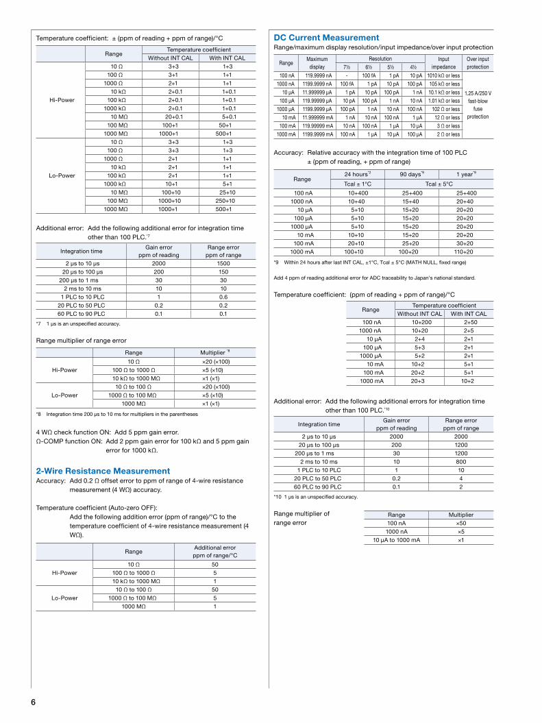
DC Current MeasurementRange/maximum display resolution/input impedance/over input protection
Accuracy: Relative accuracy with the integration time of 100 PLC ± (ppm of reading, + ppm of range)
*9 Within 24 hours after last INT CAL, ±1°C, Tcal ± 5°C (MATH NULL, fixed range)
Add 4 ppm of reading additional error for ADC traceability to Japan’s national standard.
Temperature coefficient: (ppm of reading + ppm of range)/°C
Additional error: Add the following additional errors for integration time other than 100 PLC.*10
*10 1 μs is an unspecified accuracy.
Range multiplier of range error
Range24 hours*2 90 days*9 1 year*9
Tcal ± 1°C Tcal ± 5°C
100 nA 10+400 25+400 25+4001000 nA 10+40 15+40 20+40
10 μA 5+10 15+20 20+20100 μA 5+10 15+20 20+20
1000 μA 5+10 15+20 20+2010 mA 10+10 15+20 20+20
100 mA 20+10 25+20 30+201000 mA 100+10 100+20 110+20
RangeTemperature coefficient
Without INT CAL With INT CAL100 nA 10+200 2+50
1000 nA 10+20 2+510 μA 2+4 2+1
100 μA 5+3 2+11000 μA 5+2 2+1
10 mA 10+2 5+1100 mA 20+2 5+1
1000 mA 20+3 10+2
Range Multiplier100 nA ×50
1000 nA ×510 μA to 1000 mA ×1
Integration timeGain error
ppm of readingRange error
ppm of range2 μs to 10 μs 2000 2000
20 μs to 100 μs 200 1200200 μs to 1 ms 30 1200
2 ms to 10 ms 10 8001 PLC to 10 PLC 1 10
20 PLC to 50 PLC 0.2 460 PLC to 90 PLC 0.1 2
RangeMaximum
displayResolution Input
impedanceOver input protection7½ 6½ 5½ 4½
100 nA 119.9999 nA - 100 fA 1 pA 10 pA 1010 kΩ or less
1.25 A/250 V fast-blow
fuse protection
1000 nA 1199.9999 nA 100 fA 1 pA 10 pA 100 pA 105 kΩ or less10 μA 11.999999 μA 1 pA 10 pA 100 pA 1 nA 10.1 kΩ or less
100 μA 119.99999 μA 10 pA 100 pA 1 nA 10 nA 1.01 kΩ or less1000 μA 1199.9999 μA 100 pA 1 nA 10 nA 100 nA 102 Ω or less
10 mA 11.999999 mA 1 nA 10 nA 100 nA 1 μA 12 Ω or less100 mA 119.99999 mA 10 nA 100 nA 1 μA 10 μA 3 Ω or less
1000 mA 1199.9999 mA 100 nA 1 μA 10 μA 100 μA 2 Ω or less
7
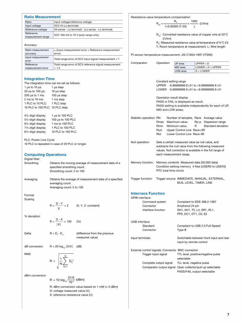
Resistance value temperature compensation
R20 = RX ×
1000 (Ω/km)
1+0.00393 (T-20) L
R20: Converted resistance value of copper wire at 20°C (Ω/km)
RX: Measured resistance value at temperature of X°C (Ω) T: Room temperature at measurement, L: Wire length
Pt sensor temperature measurement: JIS C1604-1997 (ITS90)
Comparator: Operation
Constant setting range UPPER -9.99999999 E+51 to +9.99999999 E+51 LOWER -9.99999999 E+51 to +9.99999999 E+51
Operation result displayPASS or FAIL is displayed as result.PASS setting is available independently for each of UP, MID and LOW areas.
Statistic operation: RN Number of samples, Rave Average value Rmax Maximum value, Rp-p Dispersion range Rmin Minimum value, R Standard deviation Rucl Upper Control Line Rave+3R Rlcl Lower Control Line Rave-3R
Null operation: Sets a certain measured value as null value, and subtracts the null value from the following measured values. Null correction is available in the full range of each measurement range.
Memory function: Memory contents Measured data (50,000 data) Condition setting memory 4 files (USER0 to USER3) RTC (real time clock)
Trigger function: Trigger source IMMEDIATE, MANUAL, EXTERNAL, BUS, LEVEL, TIMER, LINE
Interrace FunctionGPIB interface: Command system Compliant to IEEE 488.2-1987 Connector Amphenol 24 pin Interface function SH1, AH1, T5, L4, SR1, RL1, PP0, DC1, DT1, C0, E2
USB interface: Standard Compliant to USB 2.0 Full-Speed Connector Type B
Input terminals: Switchable between front input and rear input by remote control
External control signals: Connector BNC connector Trigger input signal TTL level, positive/negative pulse
selectable
Complete output signal TLL level, negative pulse
Comparator output signal Open collector/pull-up selectable
PASS/FAIL output selectable
Ratio Measurement
Accuracy:
Integration TimeThe integration time can be set as follows:1 μs to 10 μs: 1 μs step20 μs to 100 μs: 10 μs step200 μs to 1 ms: 100 μs step2 ms to 10 ms: 1 ms step1 PLC to 10 PLC: 1 PLC step10 PLC to 100 PLC: 10 PLC step
4½-digit display 1 μs to 100 PLC5½-digit display 100 μs to 100 PLC6½-digit display 1 ms to 100 PLC7½-digit display 1 PLC to 100 PLC8½-digit display 10 PLC to 100 PLC
PLC: Power Line Cycle10 PLC is repeated in case of 20 PLC or longer.
Computing OperationsDigital filter:Smoothing Obtains the moving average of measurement data of a
specified smoothing count. Smoothing count: 2 to 100
Averaging Obtains the average of measurement data of a specified averaging count.
Averaging count: 2 to 100
Format:Scaling
R = D - Y
× Z (X, Y, Z: constant) X
% deviation
R = D - X
× 100 (%) | X |
Delta R = Dt - Dt-1 (difference from the previous measured value)
dB conversion R = 20 log10 | D/X | (dB)
RMS
R DK2∑N
N
K=1
1=
dBm conversion
R 10 log10=
10-3
D2/X(dBm)
R: dBm conversion value based on 1 mW (= 0 dBm)D: voltage measured value (V), X: reference resistance value (Ω)
UP area UPPER < DMID area LOWER ≤ D ≤ UPPERLOW area D < LOWER
Ratio Input voltage/reference voltageInput voltage DCV Hi-Lo terminalsReference voltage (Hi sense - Lo terminal) - (Lo sense - Lo terminal)Reference measurement range
DCV 100 mV to 10 V (auto range only)
Ratio measurement accuracy
± (Input measurement error + Reference measurement error)
Input measurement error
Total range error of DCV input signal measurement × 1
Reference measurement error
Total range error of DCV reference signal measurement × 1.5
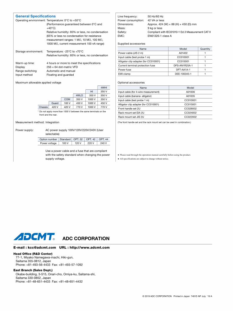
Line frequency: 50 Hz/60 HzPower consumption: 42 VA or lessDimensions: Approx. 424 (W) × 88 (H) × 450 (D) mmMass: 9 kg or lessSafety: Compliant with IEC61010-1 Ed.3 Measurement CAT IIEMC: EN61326-1 class A
Supplied accessories
Optional accessories
(The front handle set and the rack mount set can be used in combination.)
General SpecificationsOperating environment: Temperature: 0°C to +50°C
(Performance guaranteed between 0°C and +40°C)
Relative humidity: 85% or less, no condensation (65% or less no condensation for resistance
measurement ranges: 1 MΩ, 10 MΩ, 100 MΩ, 1000 MΩ, current measurement 100 nA range)
Storage environment: Temperature: -25°C to +70°C Relative humidity: 85% or less, no condensation
Warm-up time: 4 hours or more to meet the specificationsDisplay 256 × 64 dot-matric VFDRange switching Automatic and manualInput method Floating and guarded
Maximum allowable applied voltage
* Do not apply more than 1000 V between the same terminals on the
front and the rear.
Measurement method: Integration
Power supply: AC power supply 100V/120V/220V/240V (User selectable)
Use a power cable and a fuse that are compliant with the safety standard when changing the power supply voltage.
Name Model
Input cable (for 4-wire measurement) A01006
Input cable (banana- alligator) A01035
Input cable (test probe 1 m) CC010001
Alligator clip adapter (for CC010001) CC015001
Front handle set 2U CC028002
Rack mount set EIA 2U CC024002
Rack mount set JIS 2U CC022002
Name Model Quantity
Power cable (JIS 2 m) A01402 1
Input cable (test probe 1 m) CC010001 1
Alligator clip adapter (for CC010001) CC015001 1
Current terminal protection fuse DFS-AN1R25A-1 1
Power fuse DFT-AA1A-1 1
EMI clamp DEE-100345-1 1
4WHI
HI 350 V
4WLO 350 V 350 V
COM 350 V 1000 V 350 V
Guard 100 V 450 V 1000 V 450 V
Chassis 420 V 420 V 770 V 1000 V 770 V
Please read through the operation manual carefully before using the product.
All specifications are subject to change without notice.
© 2019 ADC CORPORATION Printed in Japan 7481E-NP July '19 A
Head Office (R&D Center)
East Branch (Sales Dept.)Okabe-building, 3-515, Onari-cho, Omiya-ku, Saitama-shi,Saitama 330-0852, JapanPhone: +81-48-651-4433 Fax: +81-48-651-4432
E-mail : [email protected] URL : http://www.adcmt.com
77-1, Miyako Namegawa-machi, Hiki-gun,Saitama 355-0812, JapanPhone: +81-493-56-4433 Fax: +81-493-57-1092
Option number Standard OPT. 32 OPT. 42 OPT. 44
Power voltage 100 V 120 V 220 V 240 V
Top Related