


γλώσσες
Σελίδες
Νομικός

Page 1 of 53
5.4 Electricity - Circuits 2 – Questions
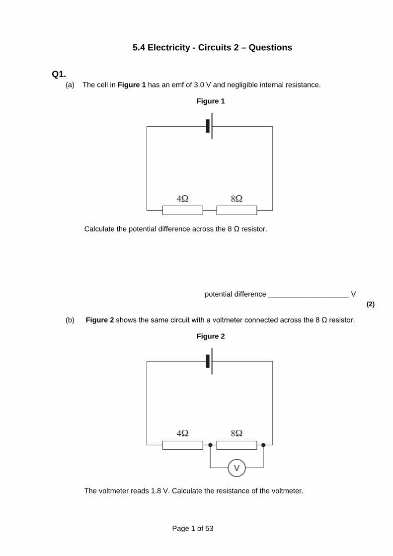
Q1. (a) The cell in Figure 1 has an emf of 3.0 V and negligible internal resistance.
Figure 1
Calculate the potential difference across the 8 Ω resistor.
potential difference ____________________ V (2)
(b) Figure 2 shows the same circuit with a voltmeter connected across the 8 Ω resistor.
Figure 2
The voltmeter reads 1.8 V. Calculate the resistance of the voltmeter.
Page 2 of 53
resistance ____________________Ω (3)
(Total 5 marks)
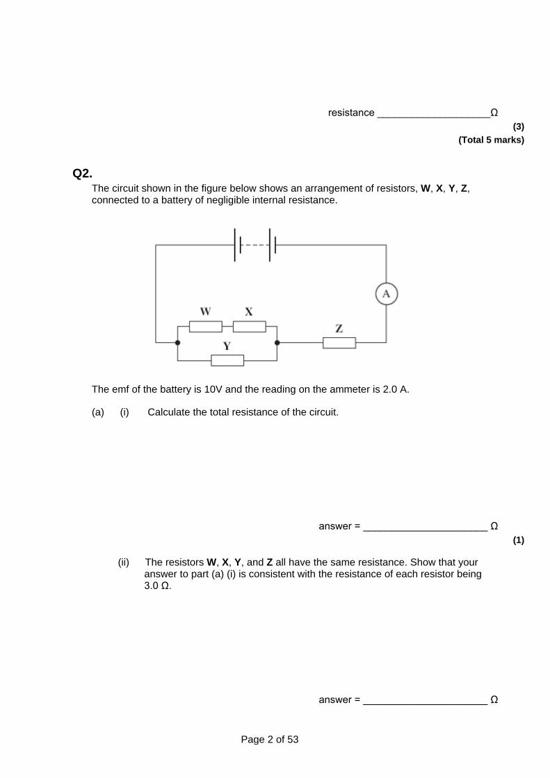
Q2. The circuit shown in the figure below shows an arrangement of resistors, W, X, Y, Z, connected to a battery of negligible internal resistance.
The emf of the battery is 10V and the reading on the ammeter is 2.0 A.
(a) (i) Calculate the total resistance of the circuit.
answer = ______________________ Ω (1)
(ii) The resistors W, X, Y, and Z all have the same resistance. Show that your answer to part (a) (i) is consistent with the resistance of each resistor being 3.0 Ω.
answer = ______________________ Ω
Page 3 of 53
(3)
(b) (i) Calculate the current through resistor Y.
answer = ______________________ A (2)
(ii) Calculate the pd across resistor W.
answer = ______________________ V (2)
(Total 8 marks)
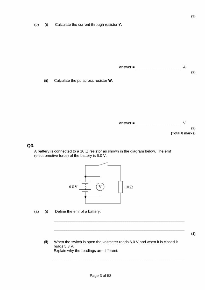
Q3. A battery is connected to a 10 Ω resistor as shown in the diagram below. The emf (electromotive force) of the battery is 6.0 V.
(a) (i) Define the emf of a battery.
______________________________________________________________
______________________________________________________________ (1)
(ii) When the switch is open the voltmeter reads 6.0 V and when it is closed it reads 5.8 V. Explain why the readings are different.
______________________________________________________________
Page 4 of 53
______________________________________________________________
______________________________________________________________
______________________________________________________________
______________________________________________________________ (2)
(b) Calculate the internal resistance of the battery.
answer = ______________________ Ω (3)
(c) State and explain why it is important for car batteries to have a very low internal resistance.
___________________________________________________________________
___________________________________________________________________
___________________________________________________________________
___________________________________________________________________
___________________________________________________________________
___________________________________________________________________ (2)
(Total 8 marks)
Q4. X and Y are two lamps. X is rated at 12 V 36 W and Y at 4.5 V 2.0 W.
(a) Calculate the current in each lamp when it is operated at its correct working voltage.
Page 5 of 53
X ____________________ A
Y ____________________ A (2)
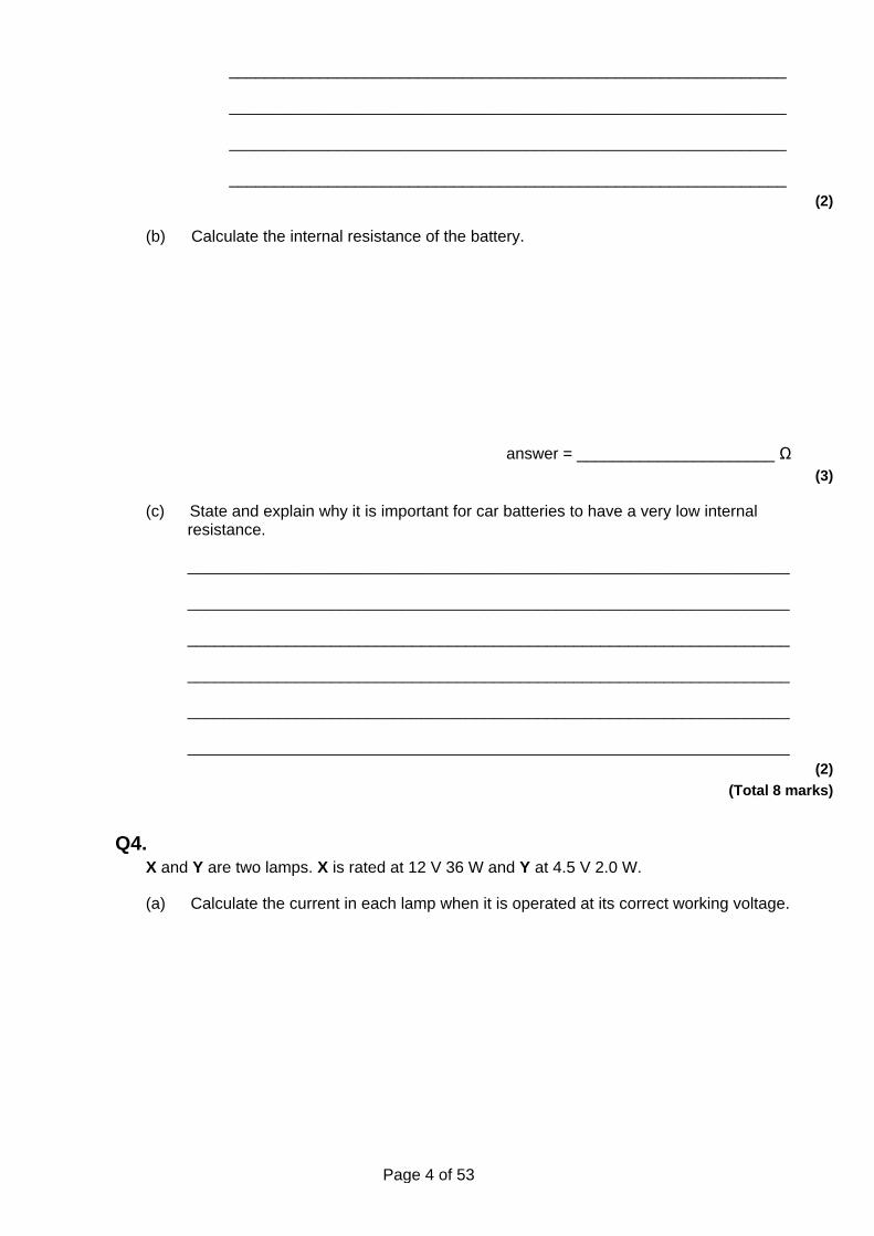
(b) The two lamps are connected in the circuit shown in the figure below. The battery has an emf of 24 V and negligible internal resistance. The resistors, R1 and R2 are chosen so that the lamps are operating at their correct working voltage.
(i) Calculate the pd across R1.
answer ____________________ V (1)
(ii) Calculate the current in R1.
answer ____________________ A (1)
(iii) Calculate the resistance of R1.
answer ____________________ Ω (1)
(iv) Calculate the pd across R2.
answer ____________________ V (1)
(v) Calculate the resistance of R2.
answer ____________________ Ω (1)
Page 6 of 53
(c) The filament of the lamp in X breaks and the lamp no longer conducts. It is observed that the voltmeter reading decreases and lamp Y glows more brightly.
(i) Explain without calculation why the voltmeter reading decreases.
______________________________________________________________
______________________________________________________________
______________________________________________________________ (2)
(ii) Explain without calculation why the lamp Y glows more brightly.
______________________________________________________________
______________________________________________________________
______________________________________________________________ (2)
(Total 11 marks)
Q5. A very high resistance voltmeter reads 15.0 V when it is connected across the terminals of a power supply.
(a) Explain why the reading on the voltmeter is equal to the emf of the power supply.
___________________________________________________________________
___________________________________________________________________
___________________________________________________________________
___________________________________________________________________
___________________________________________________________________
___________________________________________________________________ (3)
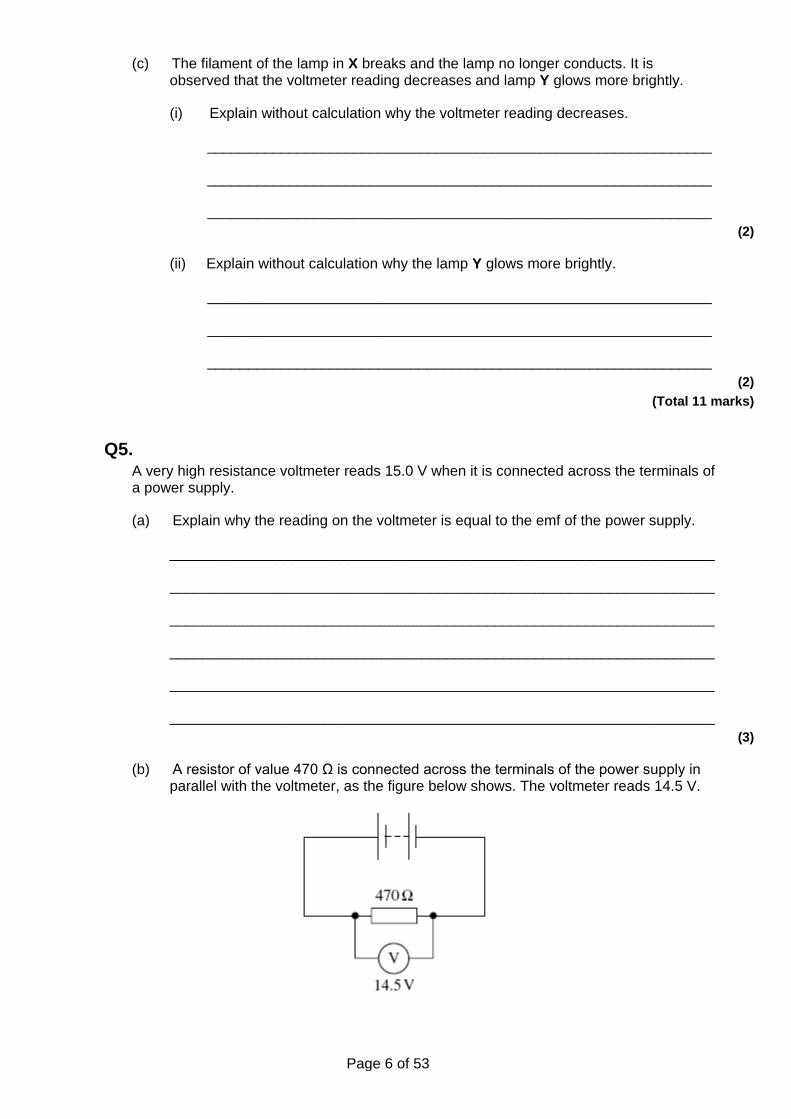
(b) A resistor of value 470 Ω is connected across the terminals of the power supply in parallel with the voltmeter, as the figure below shows. The voltmeter reads 14.5 V.
Page 7 of 53
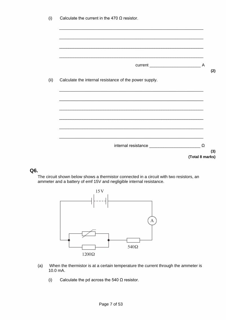
(i) Calculate the current in the 470 Ω resistor.
______________________________________________________________
______________________________________________________________
______________________________________________________________
______________________________________________________________
current ______________________ A (2)
(ii) Calculate the internal resistance of the power supply.
______________________________________________________________
______________________________________________________________
______________________________________________________________
______________________________________________________________
______________________________________________________________
______________________________________________________________
internal resistance ______________________ Ω (3)
(Total 8 marks)
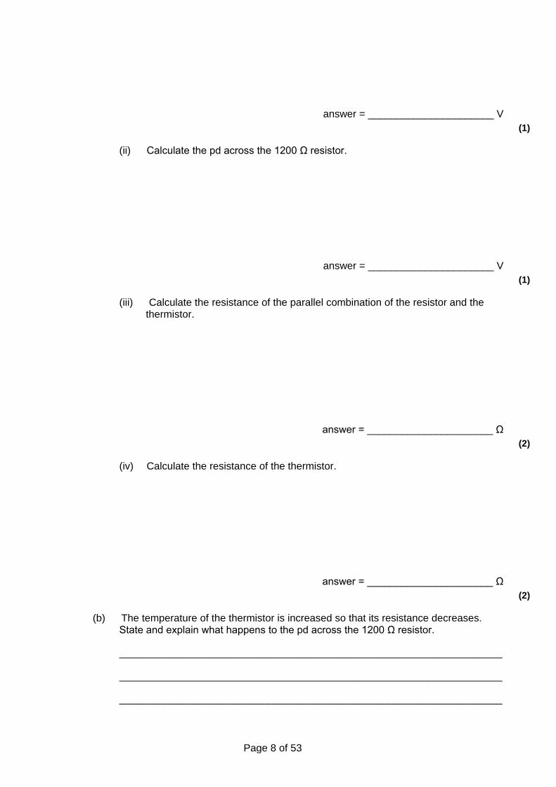
Q6. The circuit shown below shows a thermistor connected in a circuit with two resistors, an ammeter and a battery of emf 15V and negligible internal resistance.
(a) When the thermistor is at a certain temperature the current through the ammeter is 10.0 mA.
(i) Calculate the pd across the 540 Ω resistor.
Page 8 of 53
answer = ______________________ V (1)
(ii) Calculate the pd across the 1200 Ω resistor.
answer = ______________________ V (1)
(iii) Calculate the resistance of the parallel combination of the resistor and the thermistor.
answer = ______________________ Ω (2)
(iv) Calculate the resistance of the thermistor.
answer = ______________________ Ω (2)
(b) The temperature of the thermistor is increased so that its resistance decreases. State and explain what happens to the pd across the 1200 Ω resistor.
___________________________________________________________________
___________________________________________________________________
___________________________________________________________________
Page 9 of 53
___________________________________________________________________ (3)
(Total 9 marks)
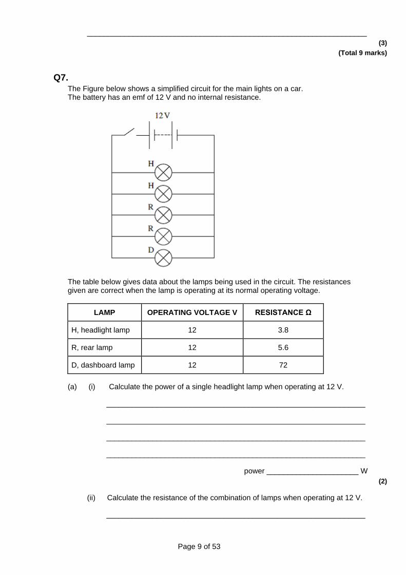
Q7. The Figure below shows a simplified circuit for the main lights on a car. The battery has an emf of 12 V and no internal resistance.
The table below gives data about the lamps being used in the circuit. The resistances given are correct when the lamp is operating at its normal operating voltage.
LAMP OPERATING VOLTAGE V RESISTANCE Ω
H, headlight lamp 12 3.8
R, rear lamp 12 5.6
D, dashboard lamp 12 72
(a) (i) Calculate the power of a single headlight lamp when operating at 12 V.
______________________________________________________________
______________________________________________________________
______________________________________________________________
______________________________________________________________
power ______________________ W (2)
(ii) Calculate the resistance of the combination of lamps when operating at 12 V.
______________________________________________________________
Page 10 of 53
______________________________________________________________
______________________________________________________________
______________________________________________________________
______________________________________________________________
resistance ______________________ Ω (3)
(iii) Calculate the total power of the combination of lamps when operating at 12 V.
______________________________________________________________
______________________________________________________________
______________________________________________________________
______________________________________________________________
______________________________________________________________
power ______________________ W (2)
(b) The battery is replaced with one of a lower emf. State and explain how the resistance of the lamps would have to change in order to achieve the same brightness.
___________________________________________________________________
___________________________________________________________________
___________________________________________________________________
___________________________________________________________________
___________________________________________________________________
___________________________________________________________________ (2)
(Total 9 marks)
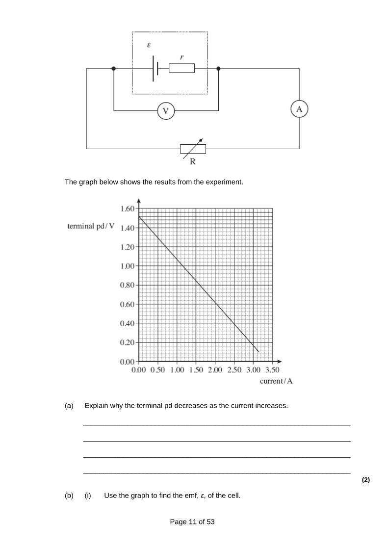
Q8. A cell of emf, ε, and internal resistance, r, is connected to a variable resistor R. The current through the cell and the terminal pd of the cell are measured as R is decreased. The circuit is shown in the figure below.
Page 11 of 53
The graph below shows the results from the experiment.
(a) Explain why the terminal pd decreases as the current increases.
___________________________________________________________________
___________________________________________________________________
___________________________________________________________________
___________________________________________________________________ (2)
(b) (i) Use the graph to find the emf, ε, of the cell.
Page 12 of 53
answer = ______________________ V (1)
(ii) Use the graph above to find the internal resistance, r, of the cell.
answer = ______________________ Ω (3)
(c) Draw a line on the graph above that shows the results obtained from a cell with
(i) the same emf but double the internal resistance of the first cell labelling your graph A.
(2)
(ii) the same emf but negligible internal resistance labelling your graph B. (1)
(d) In the original circuit shown in part (a), the variable resistor is set at a value such that the current through the cell is 0.89 A.
(i) Calculate the charge flowing through the cell in 15 s, stating an appropriate unit.
answer = ______________________ (2)
(ii) Calculate the energy dissipated in the internal resistance of the cell per second.
Page 13 of 53
answer = ______________________ W (2)
(Total 13 marks)
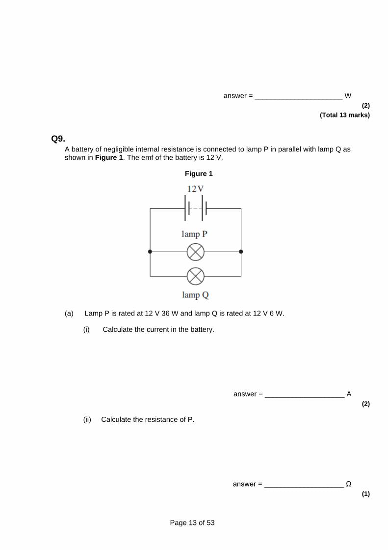
Q9. A battery of negligible internal resistance is connected to lamp P in parallel with lamp Q as shown in Figure 1. The emf of the battery is 12 V.
Figure 1
(a) Lamp P is rated at 12 V 36 W and lamp Q is rated at 12 V 6 W.
(i) Calculate the current in the battery.
answer = ____________________ A (2)
(ii) Calculate the resistance of P.
answer = ____________________ Ω (1)
Page 14 of 53
(iii) Calculate the resistance of Q.
answer = ____________________ Ω (1)
(b) State and explain the effect on the brightness of the lamps in the circuit shown in Figure 1 if the battery has a significant internal resistance.
___________________________________________________________________
___________________________________________________________________
___________________________________________________________________
___________________________________________________________________
___________________________________________________________________
___________________________________________________________________ (3)
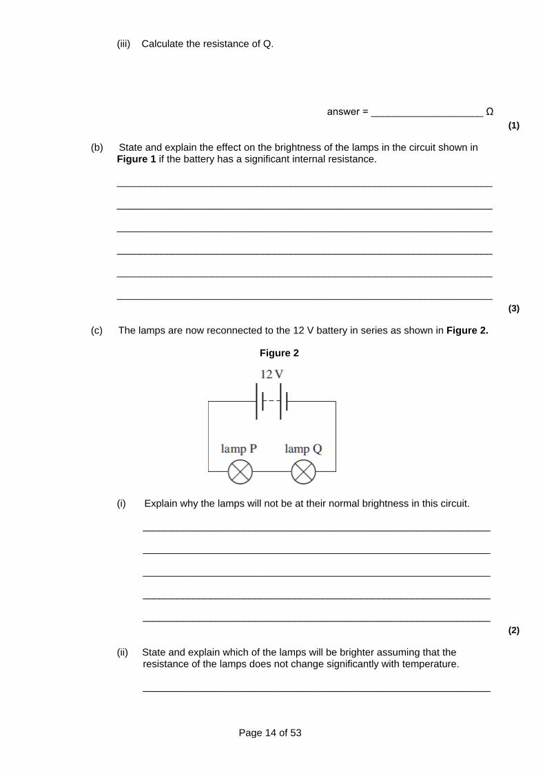
(c) The lamps are now reconnected to the 12 V battery in series as shown in Figure 2.
Figure 2
(i) Explain why the lamps will not be at their normal brightness in this circuit.
______________________________________________________________
______________________________________________________________
______________________________________________________________
______________________________________________________________
______________________________________________________________ (2)
(ii) State and explain which of the lamps will be brighter assuming that the resistance of the lamps does not change significantly with temperature.
______________________________________________________________
Page 15 of 53
______________________________________________________________
______________________________________________________________
______________________________________________________________ (3)
(Total 12 marks)
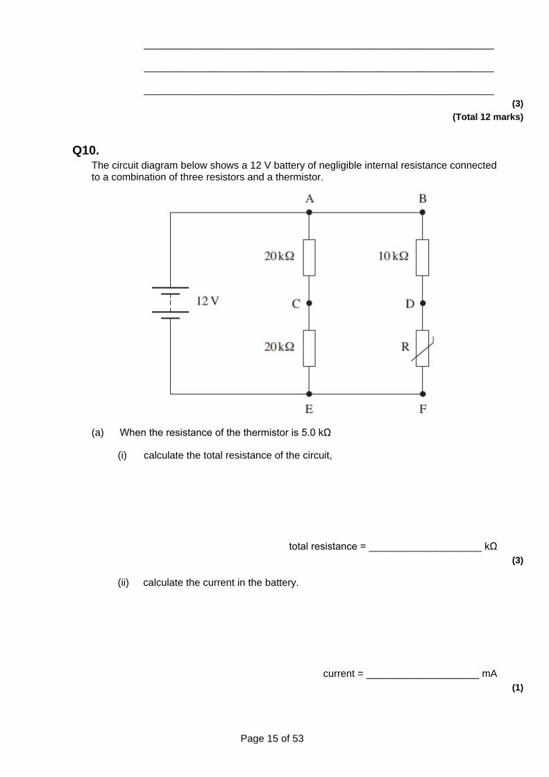
Q10. The circuit diagram below shows a 12 V battery of negligible internal resistance connected to a combination of three resistors and a thermistor.
(a) When the resistance of the thermistor is 5.0 kΩ
(i) calculate the total resistance of the circuit,
total resistance = ____________________ kΩ (3)
(ii) calculate the current in the battery.
current = ____________________ mA (1)
Page 16 of 53
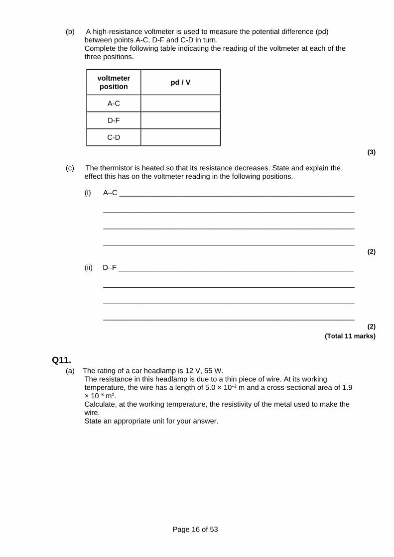
(b) A high-resistance voltmeter is used to measure the potential difference (pd) between points A-C, D-F and C-D in turn. Complete the following table indicating the reading of the voltmeter at each of the three positions.
voltmeter position pd / V
A-C
D-F
C-D
(3)
(c) The thermistor is heated so that its resistance decreases. State and explain the effect this has on the voltmeter reading in the following positions.
(i) A–C __________________________________________________________
______________________________________________________________
______________________________________________________________
______________________________________________________________ (2)
(ii) D–F __________________________________________________________
______________________________________________________________
______________________________________________________________
______________________________________________________________ (2)
(Total 11 marks)
Q11. (a) The rating of a car headlamp is 12 V, 55 W.
The resistance in this headlamp is due to a thin piece of wire. At its working temperature, the wire has a length of 5.0 × 10⁻² m and a cross-sectional area of 1.9 × 10⁻⁸ m2. Calculate, at the working temperature, the resistivity of the metal used to make the wire. State an appropriate unit for your answer.
Page 17 of 53
resistivity ______________________unit ___________ (5)
(b) (i) Define the term electromotive force (emf).
______________________________________________________________
______________________________________________________________
______________________________________________________________
______________________________________________________________ (2)
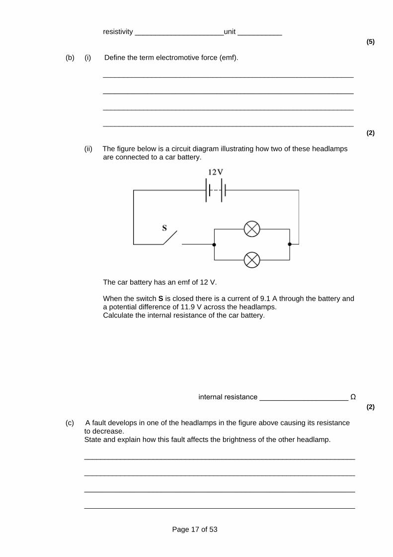
(ii) The figure below is a circuit diagram illustrating how two of these headlamps are connected to a car battery.
The car battery has an emf of 12 V.
When the switch S is closed there is a current of 9.1 A through the battery and a potential difference of 11.9 V across the headlamps. Calculate the internal resistance of the car battery.
internal resistance ______________________ Ω (2)
(c) A fault develops in one of the headlamps in the figure above causing its resistance to decrease. State and explain how this fault affects the brightness of the other headlamp.
___________________________________________________________________
___________________________________________________________________
___________________________________________________________________
___________________________________________________________________
Page 18 of 53
___________________________________________________________________
___________________________________________________________________ (3)
(Total 12 marks)
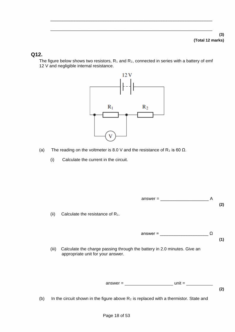
Q12. The figure below shows two resistors, R1 and R2, connected in series with a battery of emf 12 V and negligible internal resistance.
(a) The reading on the voltmeter is 8.0 V and the resistance of R2 is 60 Ω.
(i) Calculate the current in the circuit.
answer = ____________________ A (2)
(ii) Calculate the resistance of R1.
answer = ____________________ Ω (1)
(iii) Calculate the charge passing through the battery in 2.0 minutes. Give an appropriate unit for your answer.
answer = ____________________ unit = ___________ (2)
(b) In the circuit shown in the figure above R2 is replaced with a thermistor. State and
Page 19 of 53
explain what will happen to the reading on the voltmeter as the temperature of the thermistor increases.
___________________________________________________________________
___________________________________________________________________
___________________________________________________________________
___________________________________________________________________
___________________________________________________________________
___________________________________________________________________ (3)
(Total 8 marks)
Q13. A copper connecting wire is 0.75 m long and has a cross-sectional area of 1.3 × 10⁻⁷ m2.
(a) Calculate the resistance of the wire.
resistivity of copper = 1.7 × 10⁻⁷ Ωm
resistance = ____________________ Ω (2)
(b) A 12 V 25 W lamp is connected to a power supply of negligible internal resistance using two of the connecting wires. The lamp is operating at its rated power.
(i) Calculate the current flowing in the lamp.
current = ____________________ A (1)
(ii) Calculate the pd across each of the wires.
pd = ____________________ V (1)
Page 20 of 53
(iii) Calculate the emf (electromotive force) of the power supply.
emf = ____________________ V (2)
(c) The lamp used in part (b) is connected by the same two wires to a power supply of the same emf but whose internal resistance is not negligible.
State and explain what happens to the brightness of the lamp when compared to its brightness in part (b).
___________________________________________________________________
___________________________________________________________________
___________________________________________________________________
___________________________________________________________________
___________________________________________________________________
___________________________________________________________________ (2)
(Total 8 marks)
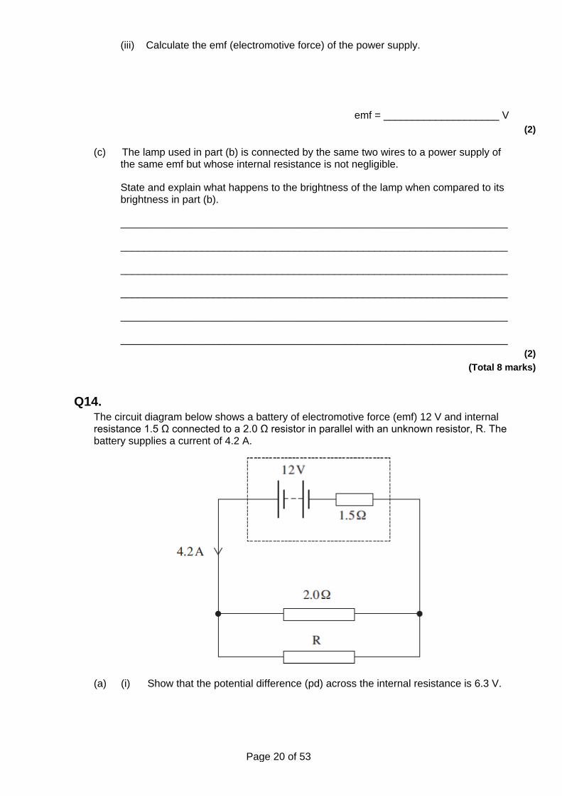
Q14. The circuit diagram below shows a battery of electromotive force (emf) 12 V and internal resistance 1.5 Ω connected to a 2.0 Ω resistor in parallel with an unknown resistor, R. The battery supplies a current of 4.2 A.
(a) (i) Show that the potential difference (pd) across the internal resistance is 6.3 V.
Page 21 of 53
(1)
(ii) Calculate the pd across the 2.0 Ω resistor.
pd ____________________V (1)
(iii) Calculate the current in the 2.0 Ω resistor.
current ____________________A (1)
(iv) Determine the current in R.
current ____________________ A (1)
(v) Calculate the resistance of R.
R ____________________ Ω (1)
(vi) Calculate the total resistance of the circuit.
circuit resistance ____________________ Ω (2)
(b) The battery converts chemical energy into electrical energy that is then dissipated in the internal resistance and the two external resistors.
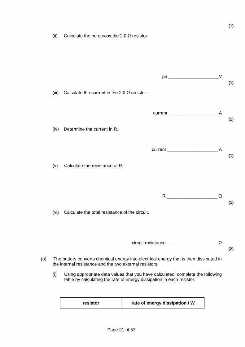
(i) Using appropriate data values that you have calculated, complete the following table by calculating the rate of energy dissipation in each resistor.
resistor rate of energy dissipation / W
Page 22 of 53
internal resistance
2.0 Ω
R
(3)
(ii) Hence show that energy is conserved in the circuit.
______________________________________________________________
______________________________________________________________ (2)
(Total 12 marks)
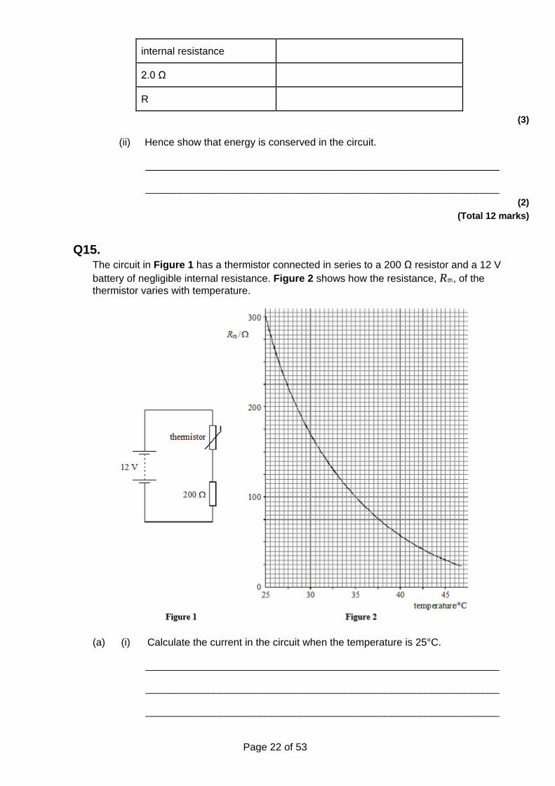
Q15. The circuit in Figure 1 has a thermistor connected in series to a 200 Ω resistor and a 12 V battery of negligible internal resistance. Figure 2 shows how the resistance, R th, of the thermistor varies with temperature.
(a) (i) Calculate the current in the circuit when the temperature is 25°C.
______________________________________________________________
______________________________________________________________
______________________________________________________________
Page 23 of 53
(ii) Calculate the potential difference across the thermistor at 25°C.
______________________________________________________________
______________________________________________________________ (3)
(b) Without further calculation, explain how you would expect the potential difference across the thermistor to change as the temperature increases from 25°C.
You may be awarded marks for the quality of written communication in your answer.
___________________________________________________________________
___________________________________________________________________
___________________________________________________________________
___________________________________________________________________
___________________________________________________________________
___________________________________________________________________ (3)
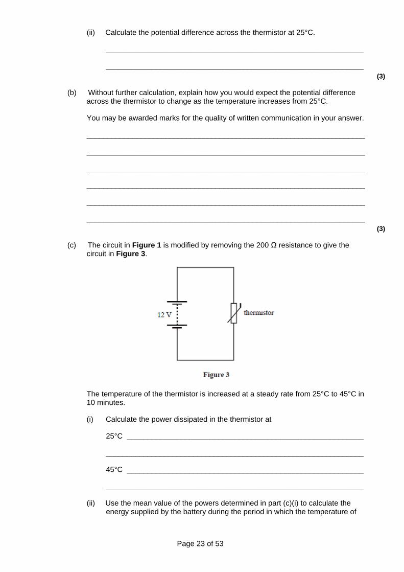
(c) The circuit in Figure 1 is modified by removing the 200 Ω resistance to give the circuit in Figure 3.
The temperature of the thermistor is increased at a steady rate from 25°C to 45°C in 10 minutes.
(i) Calculate the power dissipated in the thermistor at
25°C _________________________________________________________
______________________________________________________________
45°C _________________________________________________________
______________________________________________________________
(ii) Use the mean value of the powers determined in part (c)(i) to calculate the energy supplied by the battery during the period in which the temperature of
Page 24 of 53
the thermistor increases.
______________________________________________________________
______________________________________________________________
(iii) State why the energy value, determined in part (c)(ii) is not an accurate value.
______________________________________________________________
______________________________________________________________ (6)
(Total 12 marks)
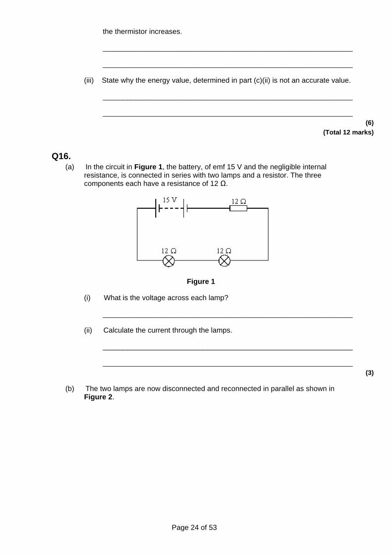
Q16. (a) In the circuit in Figure 1, the battery, of emf 15 V and the negligible internal
resistance, is connected in series with two lamps and a resistor. The three components each have a resistance of 12 Ω.
Figure 1
(i) What is the voltage across each lamp?
______________________________________________________________
(ii) Calculate the current through the lamps.
______________________________________________________________
______________________________________________________________ (3)
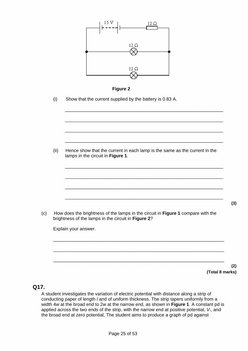
(b) The two lamps are now disconnected and reconnected in parallel as shown in Figure 2.
Page 25 of 53
Figure 2
(i) Show that the current supplied by the battery is 0.83 A.
______________________________________________________________
______________________________________________________________
______________________________________________________________
______________________________________________________________
(ii) Hence show that the current in each lamp is the same as the current in the lamps in the circuit in Figure 1.
______________________________________________________________
______________________________________________________________
______________________________________________________________
______________________________________________________________ (3)
(c) How does the brightness of the lamps in the circuit in Figure 1 compare with the brightness of the lamps in the circuit in Figure 2?
Explain your answer.
___________________________________________________________________
___________________________________________________________________
___________________________________________________________________ (2)
(Total 8 marks)
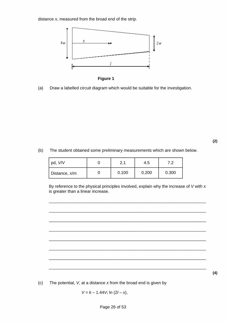
Q17. A student investigates the variation of electric potential with distance along a strip of conducting paper of length l and of uniform thickness. The strip tapers uniformly from a width 4w at the broad end to 2w at the narrow end, as shown in Figure 1. A constant pd is applied across the two ends of the strip, with the narrow end at positive potential, Vl, and the broad end at zero potential. The student aims to produce a graph of pd against
Page 26 of 53
distance x, measured from the broad end of the strip.
Figure 1
(a) Draw a labelled circuit diagram which would be suitable for the investigation.
(2)
(b) The student obtained some preliminary measurements which are shown below.
pd, V/V 0 2.1 4.5 7.2
Distance, x/m 0 0.100 0.200 0.300
By reference to the physical principles involved, explain why the increase of V with x is greater than a linear increase.
___________________________________________________________________
___________________________________________________________________
___________________________________________________________________
___________________________________________________________________
___________________________________________________________________
___________________________________________________________________
___________________________________________________________________
___________________________________________________________________ (4)
(c) The potential, V, at a distance x from the broad end is given by
V = k – 1.44Vl ln (2l – x),
Page 27 of 53
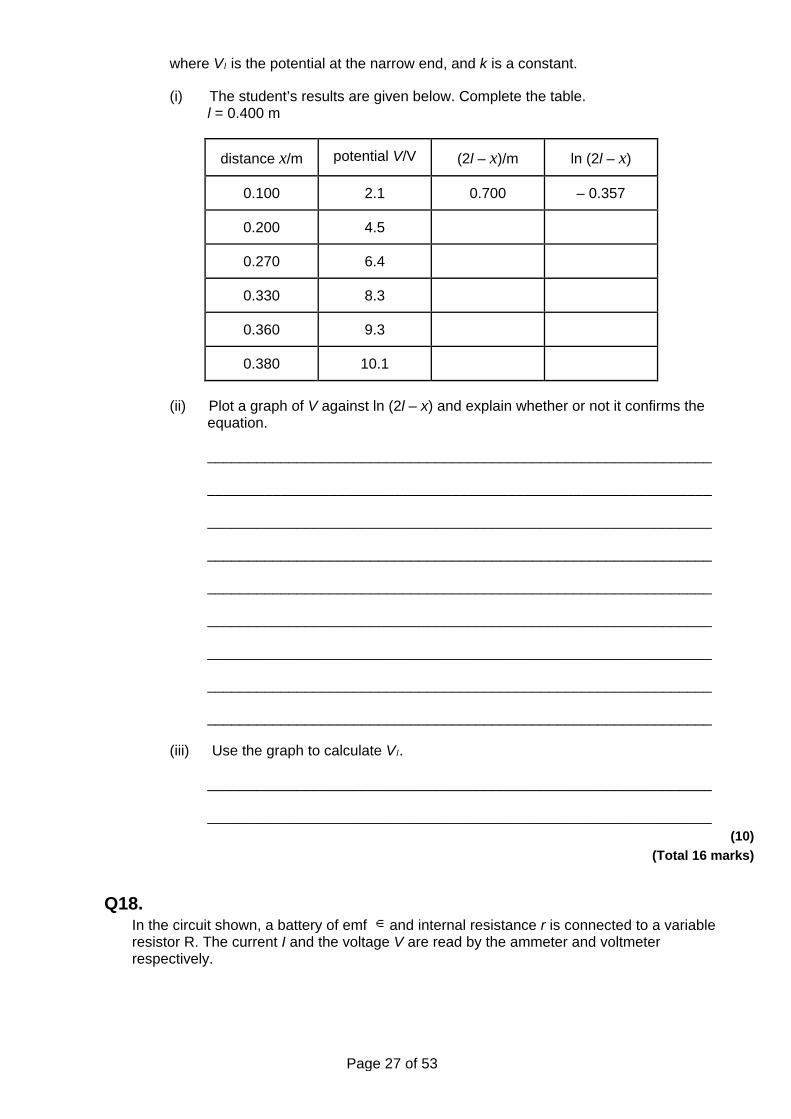
where Vl is the potential at the narrow end, and k is a constant.
(i) The student’s results are given below. Complete the table. l = 0.400 m
distance x/m potential V/V (2l – x)/m ln (2l – x)
0.100 2.1 0.700 – 0.357
0.200 4.5
0.270 6.4
0.330 8.3
0.360 9.3
0.380 10.1
(ii) Plot a graph of V against ln (2l – x) and explain whether or not it confirms the equation.
______________________________________________________________
______________________________________________________________
______________________________________________________________
______________________________________________________________
______________________________________________________________
______________________________________________________________
______________________________________________________________
______________________________________________________________
______________________________________________________________
(iii) Use the graph to calculate Vl.
______________________________________________________________
______________________________________________________________ (10)
(Total 16 marks)
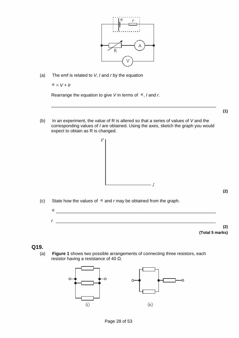
Q18. In the circuit shown, a battery of emf and internal resistance r is connected to a variable resistor R. The current I and the voltage V are read by the ammeter and voltmeter respectively.
Page 28 of 53
(a) The emf is related to V, I and r by the equation
= V + Ir
Rearrange the equation to give V in terms of , I and r.
___________________________________________________________________ (1)
(b) In an experiment, the value of R is altered so that a series of values of V and the corresponding values of I are obtained. Using the axes, sketch the graph you would expect to obtain as R is changed.
(2)
(c) State how the values of and r may be obtained from the graph.
_________________________________________________________________
r _________________________________________________________________ (2)
(Total 5 marks)
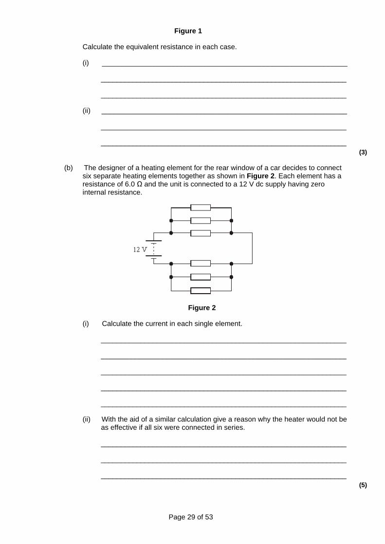
Q19. (a) Figure 1 shows two possible arrangements of connecting three resistors, each
resistor having a resistance of 40 Ω.
Page 29 of 53
Figure 1
Calculate the equivalent resistance in each case.
(i) ______________________________________________________________
______________________________________________________________
______________________________________________________________
(ii) ______________________________________________________________
______________________________________________________________
______________________________________________________________ (3)
(b) The designer of a heating element for the rear window of a car decides to connect six separate heating elements together as shown in Figure 2. Each element has a resistance of 6.0 Ω and the unit is connected to a 12 V dc supply having zero internal resistance.
Figure 2
(i) Calculate the current in each single element.
______________________________________________________________
______________________________________________________________
______________________________________________________________
______________________________________________________________
______________________________________________________________
(ii) With the aid of a similar calculation give a reason why the heater would not be as effective if all six were connected in series.
______________________________________________________________
______________________________________________________________
______________________________________________________________ (5)
Page 30 of 53
(Total 8 marks)
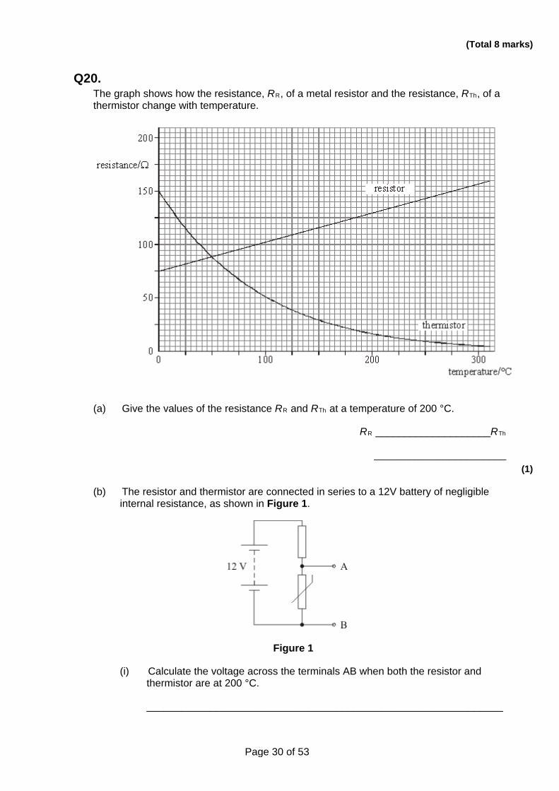
Q20. The graph shows how the resistance, RR, of a metal resistor and the resistance, RTh, of a thermistor change with temperature.
(a) Give the values of the resistance RR and RTh at a temperature of 200 °C.
RR ____________________RTh
_______________________ (1)
(b) The resistor and thermistor are connected in series to a 12V battery of negligible internal resistance, as shown in Figure 1.
Figure 1
(i) Calculate the voltage across the terminals AB when both the resistor and thermistor are at 200 °C.
______________________________________________________________
Page 31 of 53
______________________________________________________________
______________________________________________________________
(ii) Assuming that the temperature of the resistor always equals the temperature of the thermistor, deduce the temperature when the voltage across the resistor equals the voltage across the thermistor.
______________________________________________________________
______________________________________________________________
______________________________________________________________ (4)
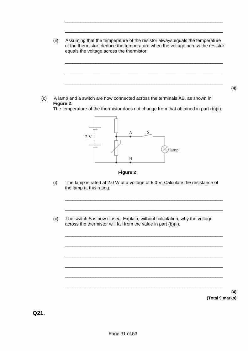
(c) A lamp and a switch are now connected across the terminals AB, as shown in Figure 2. The temperature of the thermistor does not change from that obtained in part (b)(ii).
Figure 2
(i) The lamp is rated at 2.0 W at a voltage of 6.0 V. Calculate the resistance of the lamp at this rating.
______________________________________________________________
______________________________________________________________
(ii) The switch S is now closed. Explain, without calculation, why the voltage across the thermistor will fall from the value in part (b)(ii).
______________________________________________________________
______________________________________________________________
______________________________________________________________
______________________________________________________________
______________________________________________________________
______________________________________________________________ (4)
(Total 9 marks)
Q21.
Page 32 of 53
(a) For a conductor in the form of a wire of uniform cross-sectional area, give an equation which relates its resistance to the resistivity of the material of the conductor. Define the symbols used in the equation.
___________________________________________________________________
___________________________________________________________________
___________________________________________________________________ (2)
(b) (i) An electrical heating element, made from uniform nichrome wire, is required to dissipate 500 W when connected to the 230 V mains supply. The cross-sectional area of the wire is 8.0 × 10⁻⁸ m2. Calculate the length of nichrome wire required.
resistivity of nichrome = 1.1 × 10⁻⁶ Ω m
______________________________________________________________
______________________________________________________________
______________________________________________________________
______________________________________________________________
______________________________________________________________
______________________________________________________________
(ii) Two heating elements, each rated at 230 V, 500 W are connected to the 230 mains supply
(A) in series, (B) in parallel.
Explain why only one of the circuits will provide an output of 1 kW.
______________________________________________________________
______________________________________________________________
______________________________________________________________
______________________________________________________________
______________________________________________________________
______________________________________________________________ (6)
(Total 8 marks)
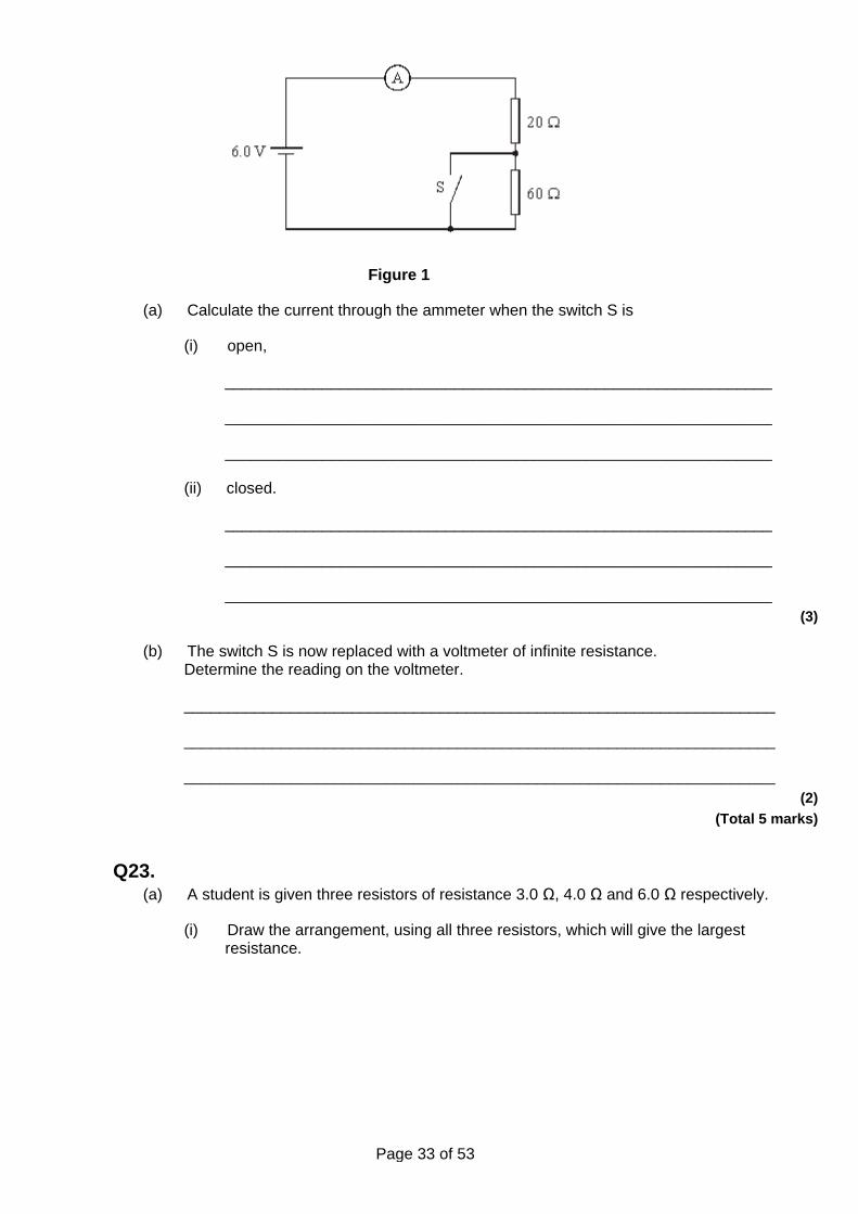
Q22. In the circuit shown in Figure 1, the battery, of emf 6.0V, has negligible internal resistance.
Page 33 of 53
Figure 1
(a) Calculate the current through the ammeter when the switch S is
(i) open,
______________________________________________________________
______________________________________________________________
______________________________________________________________
(ii) closed.
______________________________________________________________
______________________________________________________________
______________________________________________________________ (3)
(b) The switch S is now replaced with a voltmeter of infinite resistance. Determine the reading on the voltmeter.
___________________________________________________________________
___________________________________________________________________
___________________________________________________________________ (2)
(Total 5 marks)
Q23. (a) A student is given three resistors of resistance 3.0 Ω, 4.0 Ω and 6.0 Ω respectively.
(i) Draw the arrangement, using all three resistors, which will give the largest resistance.
Page 34 of 53
(ii) Calculate the resistance of the arrangement you have drawn.
______________________________________________________________
______________________________________________________________
(iii) Draw the arrangement, using all three resistors, which will give the smallest resistance.
(iv) Calculate the resistance of the arrangement you have drawn.
______________________________________________________________
______________________________________________________________
______________________________________________________________ (5)
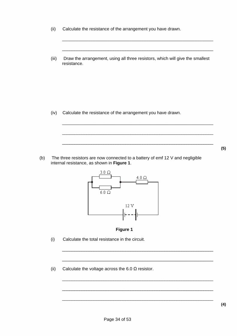
(b) The three resistors are now connected to a battery of emf 12 V and negligible internal resistance, as shown in Figure 1.
Figure 1
(i) Calculate the total resistance in the circuit.
______________________________________________________________
______________________________________________________________
(ii) Calculate the voltage across the 6.0 Ω resistor.
______________________________________________________________
______________________________________________________________
______________________________________________________________ (4)
Page 35 of 53
(Total 9 marks)
Q24. (a) (i) Describe how you would make a direct measurement of the emf ɛ of a cell,
stating the type of meter you would use.
______________________________________________________________
______________________________________________________________ (1)
(ii) Explain why this meter must have a very high resistance.
______________________________________________________________
______________________________________________________________ (1)
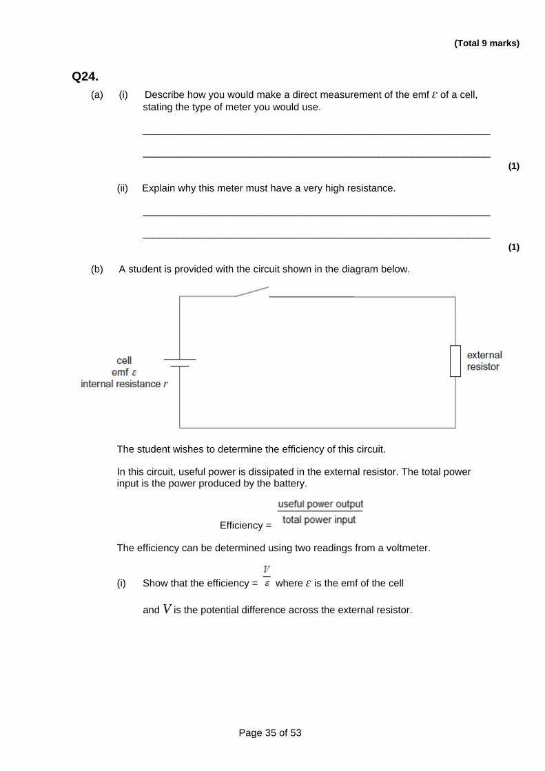
(b) A student is provided with the circuit shown in the diagram below.
The student wishes to determine the efficiency of this circuit.
In this circuit, useful power is dissipated in the external resistor. The total power input is the power produced by the battery.
Efficiency =
The efficiency can be determined using two readings from a voltmeter.
(i) Show that the efficiency = where ɛ is the emf of the cell
and V is the potential difference across the external resistor.
Page 36 of 53
(1)
(ii) Add a voltmeter to the diagram and explain how you would use this new circuit to take readings of ɛ and V.
______________________________________________________________
______________________________________________________________
______________________________________________________________ (2)
(c) Describe how you would obtain a set of readings to investigate the relationship between efficiency and the resistance of the external resistor. State any precautions you would take to ensure your readings were reliable.
___________________________________________________________________
___________________________________________________________________
___________________________________________________________________
___________________________________________________________________
___________________________________________________________________
___________________________________________________________________
___________________________________________________________________
___________________________________________________________________ (2)
(d) State and explain how you would expect the efficiency to vary as the value of R is increased.
___________________________________________________________________
___________________________________________________________________
___________________________________________________________________
___________________________________________________________________
___________________________________________________________________
___________________________________________________________________ (2)
(Total 9 marks)
Q25. (a) A set of decorative lights consists of a string of lamps. Each lamp is rated at 5.0 V,
0.40 W and is connected in series to a 230 V supply.
Page 37 of 53
Calculate
(i) the number of lamps in the set, so that each lamp operates at the correct rating,
______________________________________________________________
______________________________________________________________
(ii) the current in the circuit,
______________________________________________________________
______________________________________________________________
(iii) the resistance of each lamp,
______________________________________________________________
______________________________________________________________
(iv) the total electrical energy transferred by the set of lights in 2 hours.
______________________________________________________________
______________________________________________________________
______________________________________________________________ (5)
(b) When assembled at the factory, one set of lights inadvertently contains 10 lamps too many. All are connected in series. Assume that the resistance of each lamp is the same as that calculated in part (a) (iii).
(i) Calculate the current in this set of lights when connected to a 230 V supply.
______________________________________________________________
______________________________________________________________
______________________________________________________________
(ii) How would the brightness of each lamp in this set compare with the brightness of each lamp in the correct set?
______________________________________________________________ (3)
(Total 8 marks)
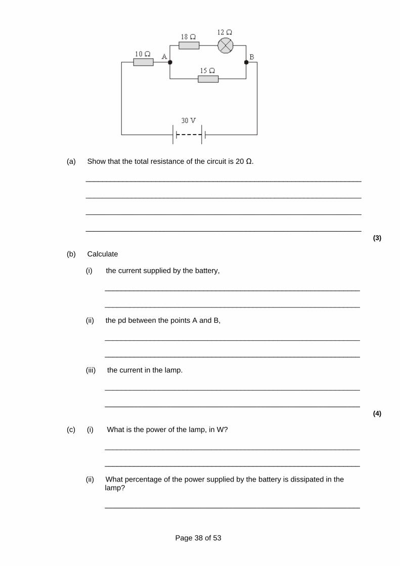
Q26. In the circuit shown in the figure below, the battery, of negligible internal resistance, has an emf of 30 V. The pd across the lamp is 6.0 V and its resistance is 12 Ω.
Page 38 of 53
(a) Show that the total resistance of the circuit is 20 Ω.
___________________________________________________________________
___________________________________________________________________
___________________________________________________________________
___________________________________________________________________ (3)
(b) Calculate
(i) the current supplied by the battery,
______________________________________________________________
______________________________________________________________
(ii) the pd between the points A and B,
______________________________________________________________
______________________________________________________________
(iii) the current in the lamp.
______________________________________________________________
______________________________________________________________ (4)
(c) (i) What is the power of the lamp, in W?
______________________________________________________________
______________________________________________________________
(ii) What percentage of the power supplied by the battery is dissipated in the lamp?
______________________________________________________________
Page 39 of 53
______________________________________________________________ (3)
(Total 10 marks)
Q27. (a) A student wishes to measure the resistivity of the material of a uniform resistance
wire. The available apparatus includes a battery, a switch, a variable resistor, an ammeter and a voltmeter.
(i) Draw a circuit diagram which incorporates some or all of this apparatus and which enables the student to determine the resistivity of the material.
(ii) State the measurements which must be made to ensure that a reliable value of the resistivity is obtained.
______________________________________________________________
______________________________________________________________
______________________________________________________________
______________________________________________________________
______________________________________________________________
______________________________________________________________
(iii) Explain how a value of the resistivity would be obtained from the measurements.
______________________________________________________________
______________________________________________________________
______________________________________________________________
______________________________________________________________
______________________________________________________________
______________________________________________________________ (10)
(b) A wire made from tin with cross-sectional area 7.8 × 10⁻⁹ m2, has a pd of 2.0 V across it. Calculate the minimum length of wire needed so that the current through it
Page 40 of 53
does not exceed 4.0 A.
resistivity of tin = 1.1 × 10⁻⁷ Ω m
___________________________________________________________________
___________________________________________________________________
___________________________________________________________________
___________________________________________________________________ (2)
(Total 12 marks)
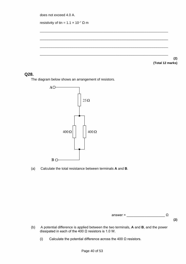
Q28. The diagram below shows an arrangement of resistors.
(a) Calculate the total resistance between terminals A and B.
answer = ____________________ Ω (2)
(b) A potential difference is applied between the two terminals, A and B, and the power dissipated in each of the 400 Ω resistors is 1.0 W.
(i) Calculate the potential difference across the 400 Ω resistors.
Page 41 of 53
answer = ____________________ V
(ii) Calculate the current through the 25 Ω resistor.
answer = ____________________ A
(iii) Calculate the potential difference applied to terminals A and B.
answer = ____________________ V (6)
(Total 8 marks)
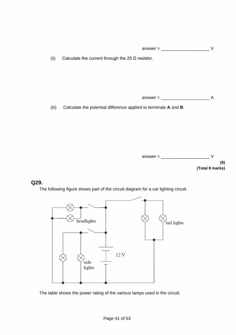
Q29. The following figure shows part of the circuit diagram for a car lighting circuit.
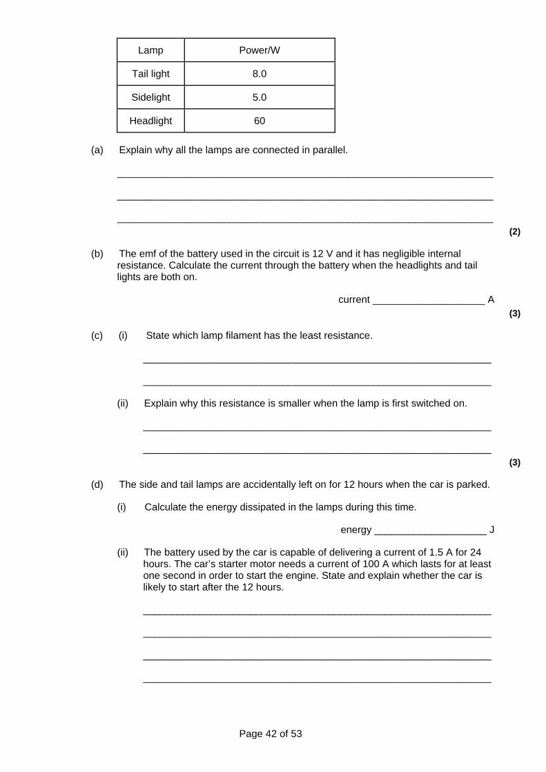
The table shows the power rating of the various lamps used in the circuit.
Page 42 of 53
Lamp Power/W
Tail light 8.0
Sidelight 5.0
Headlight 60
(a) Explain why all the lamps are connected in parallel.
___________________________________________________________________
___________________________________________________________________
___________________________________________________________________ (2)
(b) The emf of the battery used in the circuit is 12 V and it has negligible internal resistance. Calculate the current through the battery when the headlights and tail lights are both on.
current ____________________ A (3)
(c) (i) State which lamp filament has the least resistance.
______________________________________________________________
______________________________________________________________
(ii) Explain why this resistance is smaller when the lamp is first switched on.
______________________________________________________________
______________________________________________________________ (3)
(d) The side and tail lamps are accidentally left on for 12 hours when the car is parked.
(i) Calculate the energy dissipated in the lamps during this time.
energy ____________________ J
(ii) The battery used by the car is capable of delivering a current of 1.5 A for 24 hours. The car’s starter motor needs a current of 100 A which lasts for at least one second in order to start the engine. State and explain whether the car is likely to start after the 12 hours.
______________________________________________________________
______________________________________________________________
______________________________________________________________
______________________________________________________________
Page 43 of 53
______________________________________________________________
______________________________________________________________ (5)
(Total 13 marks)
Q30. A student wishes to collect data so he can plot the I-V curve for a semiconductor diode.
(a) (i) Draw a suitable diagram of the circuit that would enable the student to collect this data.
(3)
(ii) Describe the procedure the student would follow in order to obtain an I-V curve for the semiconductor diode.
The quality of your written communication will be assessed in this question.
______________________________________________________________
______________________________________________________________
______________________________________________________________
______________________________________________________________
______________________________________________________________
______________________________________________________________
______________________________________________________________
______________________________________________________________
______________________________________________________________
______________________________________________________________
______________________________________________________________ (6)
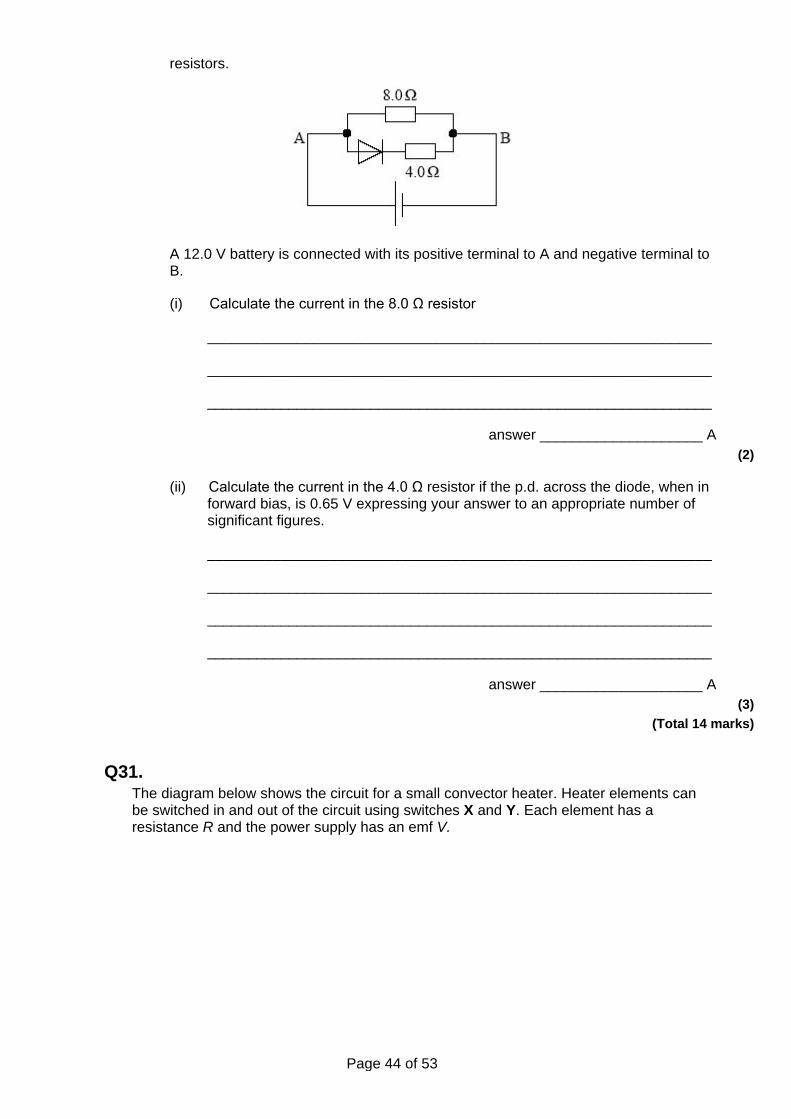
(b) The diagram below shows an arrangement of a semiconducting diode and two
Page 44 of 53
resistors.
A 12.0 V battery is connected with its positive terminal to A and negative terminal to B.
(i) Calculate the current in the 8.0 Ω resistor
______________________________________________________________
______________________________________________________________
______________________________________________________________
answer ____________________ A (2)
(ii) Calculate the current in the 4.0 Ω resistor if the p.d. across the diode, when in forward bias, is 0.65 V expressing your answer to an appropriate number of significant figures.
______________________________________________________________
______________________________________________________________
______________________________________________________________
______________________________________________________________
answer ____________________ A (3)
(Total 14 marks)
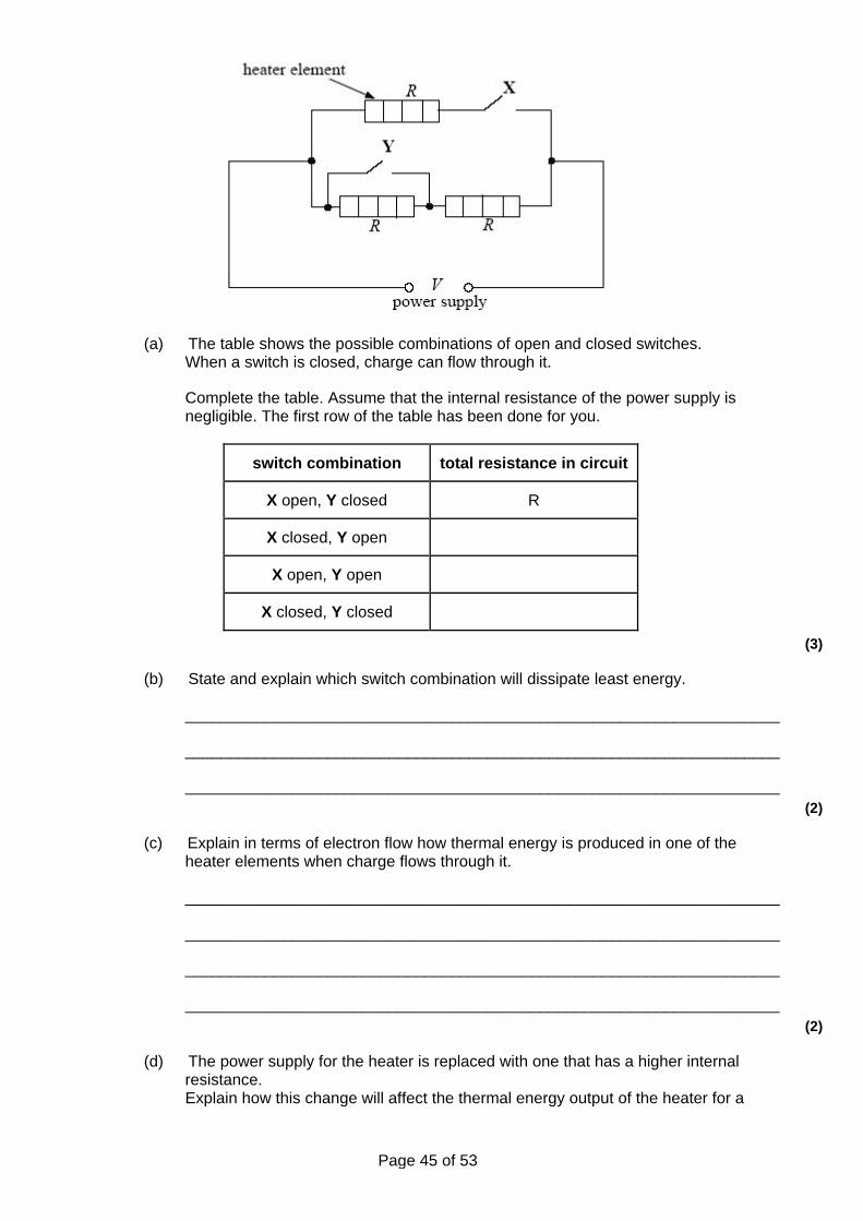
Q31. The diagram below shows the circuit for a small convector heater. Heater elements can be switched in and out of the circuit using switches X and Y. Each element has a resistance R and the power supply has an emf V.
Page 45 of 53
(a) The table shows the possible combinations of open and closed switches. When a switch is closed, charge can flow through it.
Complete the table. Assume that the internal resistance of the power supply is negligible. The first row of the table has been done for you.
switch combination total resistance in circuit
X open, Y closed R
X closed, Y open
X open, Y open
X closed, Y closed
(3)
(b) State and explain which switch combination will dissipate least energy.
___________________________________________________________________
___________________________________________________________________
___________________________________________________________________ (2)
(c) Explain in terms of electron flow how thermal energy is produced in one of the heater elements when charge flows through it.
___________________________________________________________________
___________________________________________________________________
___________________________________________________________________
___________________________________________________________________ (2)
(d) The power supply for the heater is replaced with one that has a higher internal resistance. Explain how this change will affect the thermal energy output of the heater for a
Page 46 of 53
given switch combination. State which switch combination will be affected most by the change.
___________________________________________________________________
___________________________________________________________________
___________________________________________________________________
___________________________________________________________________ (3)
(e) The resistance of each heater element is 68 Ω. Each one is made from 7.2 m of nichrome wire wound on a rod.
(i) Calculate the radius of the nichrome wire.
resistivity of nichrome = 1.1 × 10⁻⁶ Ω m
radius ____________________ m (2)
(ii) Suggest two properties that the rod must have to make it suitable in this application.
______________________________________________________________
______________________________________________________________
______________________________________________________________ (2)
(Total 14 marks)
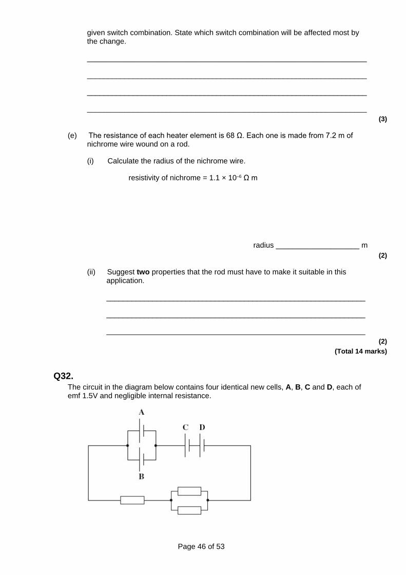
Q32. The circuit in the diagram below contains four identical new cells, A, B, C and D, each of emf 1.5V and negligible internal resistance.
Page 47 of 53
(a) The resistance of each resistor is 4.0 Ω.
(i) Calculate the total resistance of the circuit.
answer = ____________________ Ω (1)
(ii) Calculate the total emf of the combination of cells.
answer = ____________________ V (1)
(iii) Calculate the current passing through cell A.
answer = ____________________ A (2)
(iv) Calculate the charge passing through cell A in five minutes, stating an appropriate unit.
answer = ____________________ (2)
(b) Each of the cells can provide the same amount of electrical energy before going flat. State and explain which two cells in this circuit you would expect to go flat first.
___________________________________________________________________
___________________________________________________________________
___________________________________________________________________
___________________________________________________________________
Page 48 of 53
___________________________________________________________________
___________________________________________________________________ (3)
(Total 9 marks)
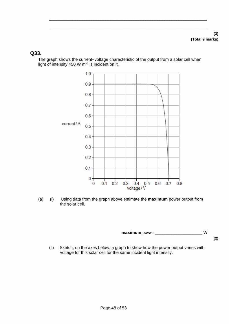
Q33. The graph shows the current−voltage characteristic of the output from a solar cell when light of intensity 450 W m−2 is incident on it.
(a) (i) Using data from the graph above estimate the maximum power output from the solar cell.
maximum power ____________________ W (2)
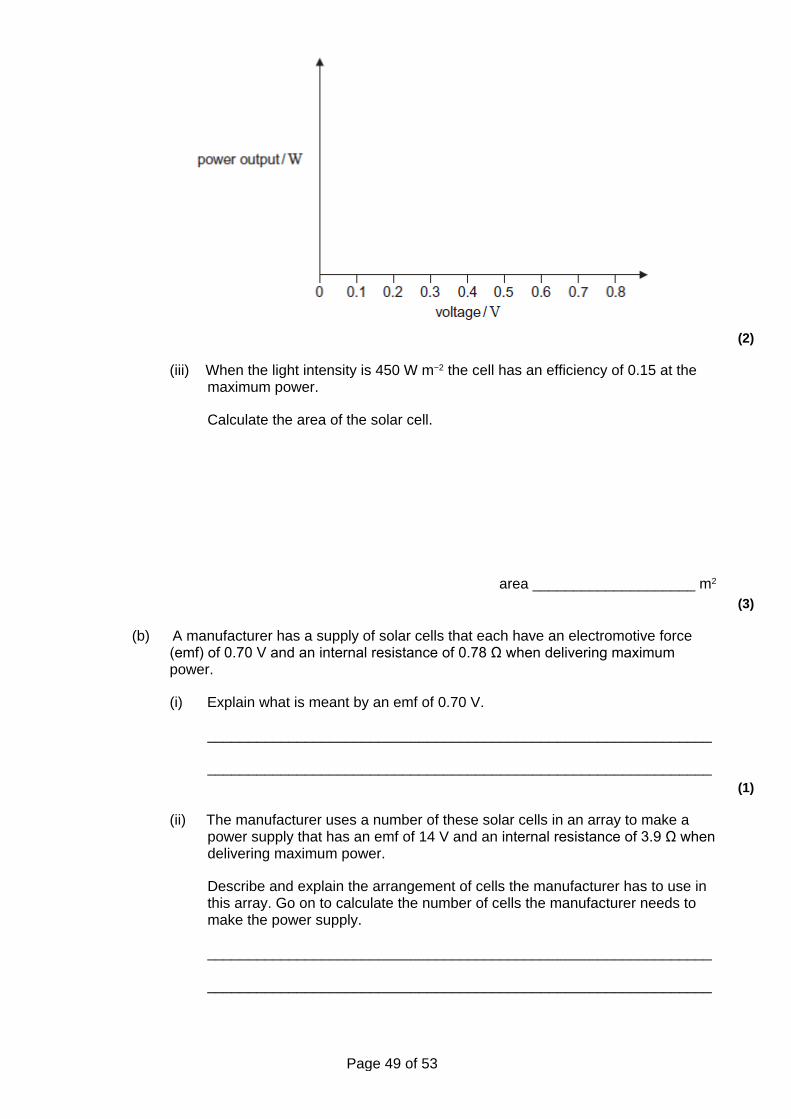
(ii) Sketch, on the axes below, a graph to show how the power output varies with voltage for this solar cell for the same incident light intensity.
Page 49 of 53
(2)
(iii) When the light intensity is 450 W m−2 the cell has an efficiency of 0.15 at the maximum power.
Calculate the area of the solar cell.
area ____________________ m2
(3)
(b) A manufacturer has a supply of solar cells that each have an electromotive force (emf) of 0.70 V and an internal resistance of 0.78 Ω when delivering maximum power.
(i) Explain what is meant by an emf of 0.70 V.
______________________________________________________________
______________________________________________________________ (1)
(ii) The manufacturer uses a number of these solar cells in an array to make a power supply that has an emf of 14 V and an internal resistance of 3.9 Ω when delivering maximum power.
Describe and explain the arrangement of cells the manufacturer has to use in this array. Go on to calculate the number of cells the manufacturer needs to make the power supply.
______________________________________________________________
______________________________________________________________
Page 50 of 53
______________________________________________________________
______________________________________________________________
______________________________________________________________
number of cells ____________________ (4)
(c) Communications satellites use solar cells to generate electrical power. Discuss why solar cells are appropriate for this task.
Your answer should refer to: • any additional features that would be needed to ensure that the satellite’s
electrical systems operate continuously • whether solar cell arrays are appropriate for space probes that travel to the
edge of the solar system.
The quality of your written communication will be assessed in your answer. (6)
(Total 18 marks)
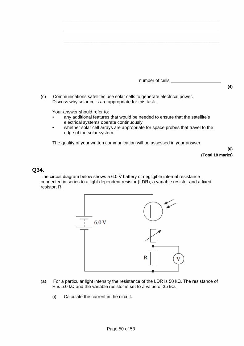
Q34. The circuit diagram below shows a 6.0 V battery of negligible internal resistance connected in series to a light dependent resistor (LDR), a variable resistor and a fixed resistor, R.
(a) For a particular light intensity the resistance of the LDR is 50 kΩ. The resistance of R is 5.0 kΩ and the variable resistor is set to a value of 35 kΩ.
(i) Calculate the current in the circuit.
Page 51 of 53
current____________________A (2)
(ii) Calculate the reading on the voltmeter.
voltmeter reading ____________________V (2)
(b) State and explain what happens to the reading on the voltmeter if the intensity of the light incident on the LDR increases.
___________________________________________________________________
___________________________________________________________________
___________________________________________________________________ (2)
(c) For a certain application at a particular light intensity the pd across R needs to be 0.75 V. The resistance of the LDR at this intensity is 5.0 kΩ.
Calculate the required resistance of the variable resistor in this situation.
resistance ____________________ Ω (3)
(Total 9 marks)
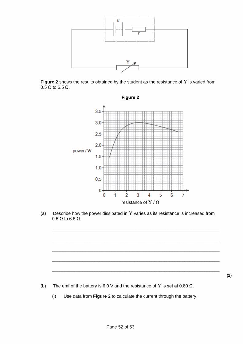
Q35. A student investigates how the power dissipated in a variable resistor, Y, varies as the resistance is altered. Figure 1 shows the circuit the student uses. Y is connected to a battery of emf ε and internal resistance r.
Figure 1
Page 52 of 53
Figure 2 shows the results obtained by the student as the resistance of Y is varied from 0.5 Ω to 6.5 Ω.
Figure 2
resistance of Y / Ω
(a) Describe how the power dissipated in Y varies as its resistance is increased from 0.5 Ω to 6.5 Ω.
___________________________________________________________________
___________________________________________________________________
___________________________________________________________________
___________________________________________________________________
___________________________________________________________________ (2)
(b) The emf of the battery is 6.0 V and the resistance of Y is set at 0.80 Ω.
(i) Use data from Figure 2 to calculate the current through the battery.
Page 53 of 53
current ____________________ A (3)
(ii) Calculate the voltage across Y.
voltage ____________________ V (2)
(iii) Calculate the internal resistance of the battery.
internal resistance ____________________ Ω (2)
(c) The student repeats the experiment with a battery of the same emf but negligible internal resistance. State and explain how you would now expect the power dissipated in Y to vary as the resistance of Y is increased from 0.5 Ω to 6.5 Ω.
___________________________________________________________________
___________________________________________________________________
___________________________________________________________________
___________________________________________________________________
___________________________________________________________________ (3)
(Total 12 marks)
Top Related