


γλώσσες
Σελίδες
Νομικός

100 μA, 320 nT/√Hz, 3-AXIS LORENTZ FORCE MEMS MAGNETOMETER
Giacomo Laghi1, Antonio F. Longoni1, Paolo Minotti1, Alessandro Tocchio2, and Giacomo Langfelder1 1Dipartimento di Elettronica, Informazione e Bioingegneria, Politecnico di Milano, Italy
2AMS Division, ST Microelectronics, Cornaredo (MI), Italy ABSTRACT
The work presents a module for earth magnetic field measurements based on four microelectromechanical devices: one out-of-plane and two in-plane differential Lorentz-force magnetometers, and a Tang resonator. The latter is used to provide the reference frequency in off-resonance operation, a way that enables the magnetometers to share the same Lorentz current, giving an intrinsic 3-fold consumption decrease. At the same time, using multiple-loop design, a 5-fold larger sensitivity and a 4-fold better resolution are obtained with respect to previous implementations that used the same process. The system operating bandwidth is electronically selectable up to 50 Hz. KEYWORDS
MEMS magnetometer, mode-split operation, Tang resonator, multi-axis sensing, multi-parameter sensing. INTRODUCTION
Most Lorentz-force MEMS magnetometers in the literature are operated in amplitude modulation (AM) at resonance, with (i) an inherent trade-off between resolution and bandwidth, (ii) remarkable challenges in providing the reference frequency for resonant operation without offset issues, and (iii) poor long-term scale-factor stability due to the quality factor changes with temperature [1, 2, 3]. To bypass these issues, two main approaches were proposed in recent works. The first one is based on frequency modulated (FM) operation, where the Lorentz force creates a compressive or tensile stress on the resonator, causing its resonance frequency to shift [4, 5]. The second one is an AM technique, where the device is however driven with a current at a frequency slightly lower than resonance [6, 7]. In this way the bandwidth of the device is no longer directly dependent on its quality factor (Q), solving the first issue indicated above and opening ways to improve the resolution (e.g. by lowering the package pressure without worrying about the system bandwidth). Further, as the working frequency differs from resonance, an improvement on scale-factor stability is observed [8]: the sensitivity to small variations of the frequency mismatch is minimized with respect to resonant operation, thus solving the second and third issues above for resonance operation. However, this solution carries two new drawbacks: (i) an inherently lower scale-factor and (ii) the need for a new drive reference, suitably shifted from the magnetometer resonance.
The module shown in Fig. 1 addresses the two remaining points above: it consists of one magnetometer per sensing axis and a resonator. The magnetometers feature
multiple loops for current re-circulation [2], which linearly improve both scale-factor and resolution. The resonator, embedded in an oscillator [9], provides the reference signal, at the mismatch frequency, for the drive current. The current flows as depicted through all the magnetic sensors, designed to operate off-resonance, 200 Hz above the resonator.
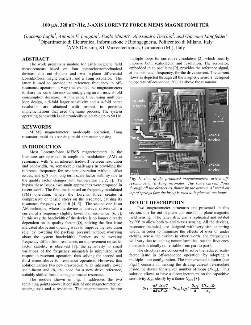
Fig. 1: view of the proposed magnetometers, driven off-resonance by a Tang resonator. The same current flows through all the devices as shown by the arrows. Al metal on top of springs (see the inset) is used to implement ten loops. DEVICE DESCRIPTION
Two magnetometer structures are presented in this section: one for out-of-plane and one for in-plane magnetic field sensing. The latter structure is replicated and rotated by 90° to allow both x- and y-axis sensing. All the devices, resonator included, are designed with very similar spring width, in order to minimize the effects of over or under etching across the wafer (in other words, the frequencies will vary due to etching nonuniformities, but the frequency mismatch is ideally quite stable from part to part).
The structures are conceived to solve the reduced scale-factor issue in off-resonance operation, by adopting a multiple-loop configuration. The implemented solution (see Fig.1) consists in making the driving current re-circulate inside the device for a given number of loops (Nloop). This solution allows to have a direct increment on the capacitive sensitivity SCB, ideally by a factor Nloop [8]:
where the formula assumes Ncells differential capacitive sensing cells, each with a value C0, for a rest gap x0. Leff is the effective spring length and Qeff is the effective quality factor, which represents the residual amplification obtained in off-resonance operation [6]. I is the peak amplitude of the injected current and k the device mechanical stiffness.
To enable the desired current re-circulation, Al metal strips are deposited on the polysilicon structure, as shown in the inset of Fig.1. In this way the resistivity of the loops path decreases, becoming much lower than for parasitic paths through polysilicon, even in absence of electrical isolation between metal and polysilicon itself. This concept differs from previous multi-loop implementations [2], and enables the direct integration of such a structure in industrial technologies, without adding any new process step [10]. The process consists of an epitaxial growth of a 22-µm-thick heavily doped layer of polycrystalline silicon that, once etched and released, forms the suspended frame. Beneath the structure, a thin polysilicon layer is used for electrical interconnections and vertical electrodes. The devices are encapsulated at relatively low pressure (about 0.7 mbar) through the use of getter materials and glassfrit bonding. In principle, there are no conceptual problems in further reducing the package pressure, since the trade-off between scale-factor and bandwidth is solved. The Brownian noise σB at an absolute temperature T turns out to be:
where the damping coefficient b is directly dependent on the package pressure but it does not limit the system bandwidth.
Out-of-plane field sensing structure
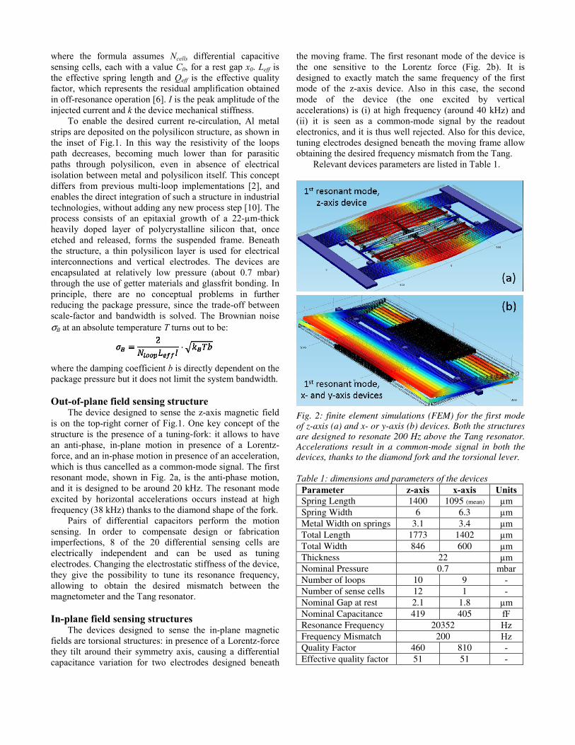
The device designed to sense the z-axis magnetic field is on the top-right corner of Fig.1. One key concept of the structure is the presence of a tuning-fork: it allows to have an anti-phase, in-plane motion in presence of a Lorentz-force, and an in-phase motion in presence of an acceleration, which is thus cancelled as a common-mode signal. The first resonant mode, shown in Fig. 2a, is the anti-phase motion, and it is designed to be around 20 kHz. The resonant mode excited by horizontal accelerations occurs instead at high frequency (38 kHz) thanks to the diamond shape of the fork.
Pairs of differential capacitors perform the motion sensing. In order to compensate design or fabrication imperfections, 8 of the 20 differential sensing cells are electrically independent and can be used as tuning electrodes. Changing the electrostatic stiffness of the device, they give the possibility to tune its resonance frequency, allowing to obtain the desired mismatch between the magnetometer and the Tang resonator.
In-plane field sensing structures
The devices designed to sense the in-plane magnetic fields are torsional structures: in presence of a Lorentz-force they tilt around their symmetry axis, causing a differential capacitance variation for two electrodes designed beneath
the moving frame. The first resonant mode of the device is the one sensitive to the Lorentz force (Fig. 2b). It is designed to exactly match the same frequency of the first mode of the z-axis device. Also in this case, the second mode of the device (the one excited by vertical accelerations) is (i) at high frequency (around 40 kHz) and (ii) it is seen as a common-mode signal by the readout electronics, and it is thus well rejected. Also for this device, tuning electrodes designed beneath the moving frame allow obtaining the desired frequency mismatch from the Tang.
Relevant devices parameters are listed in Table 1.
Fig. 2: finite element simulations (FEM) for the first mode of z-axis (a) and x- or y-axis (b) devices. Both the structures are designed to resonate 200 Hz above the Tang resonator. Accelerations result in a common-mode signal in both the devices, thanks to the diamond fork and the torsional lever.
Table 1: dimensions and parameters of the devices
Parameter z-axis x-axis Units Spring Length 1400 1095 (mean) µm Spring Width 6 6.3 µm Metal Width on springs 3.1 3.4 µm Total Length 1773 1402 µm Total Width 846 600 µm Thickness 22 µm Nominal Pressure 0.7 mbar Number of loops 10 9 - Number of sense cells 12 1 - Nominal Gap at rest 2.1 1.8 µm Nominal Capacitance 419 405 fF Resonance Frequency 20352 Hz Frequency Mismatch 200 Hz Quality Factor 460 810 - Effective quality factor 51 51 -
DRIVING AND READOUT ELECTRONICS The driving current for the sensors is provided by a
trans-impedance amplifier (TIA)-based oscillator, whose resonant element is the Tang resonator shown in Fig.1. The oscillator circuit is formed by three stages: (i) the TIA stage, that converts the motional current into a voltage at its output, (ii) a high-gain stage, that makes the voltage saturate between the supplies and (iii) a de-gain stage that closes the ring and avoids mechanical nonlinearities of the resonator. The saturated voltage of the high-gain stage is sent to a voltage-current converter with selectable conversion factor. In this way, the peak value of the driving current is precisely known. The current flows along the three devices, connected in series. The readout can be performed by identical capacitive chains, as shown in Fig. 3.
Fig. 3: block scheme of the system, with a trans-impedance (TIA) oscillator built around the Tang resonator, and three, high-resolution, capacitive sensing interfaces.
Measurements of this work were actually performed with a single-axis board, reading one device at a time through a single readout chain. The two sets of sensing plates are kept at a fixed potential through the virtual ground of two charge amplifier stages, used to convert the current flowing out from the MEMS stators to voltage signals at their outputs. These two signals, ideally with the same amplitude and a phase shift, are high-pass filtered and sent as inputs to an INA stage, that further amplifies the differential signal, at the same time rejecting any common mode. The resulting sine wave is demodulated and low-pass filtered through a lock-in amplifier with selectable filtering bandwidth, driven by the Tang resonator. The noise performances of the described readout chain [7] are limited by the thermal noise of the feedback resistance of the charge amplifiers (RF = 600 MΩ):
Compared to the MEMS noise, this contribution is negligible around resonance, but becomes the dominant one for large frequency mismatches, due to the lower device scale-factor. At the used 200 Hz mismatch, the two contributions are expected to be balanced. EXPERIMENTAL RESULTS
Measurements are performed using a 3-axis Helmholtz coil field generator that, coupled to a custom LabVIEW interface, allows generating quasi-stationary and dynamic magnetic fields. An acquisition board from Measurement Computing is used as the analog-to-digital converter.
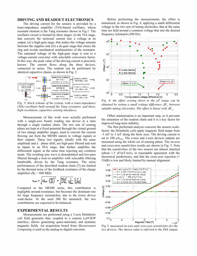
Before performing the measurements, the offset is minimized, as shown in Fig. 4, applying a small differential voltage to the two sets of tuning electrodes, that at the same time are held around a common voltage that sets the desired frequency mismatch (200 Hz).
Fig. 4: the offset zeroing down to the µT range can be obtained by setting a small voltage difference ΔVos between suitable tuning electrodes. The offset is linear with ΔVos.
Offset minimization is an important step, as it prevents the saturation of the readout chain and it is a key factor for improved long-term stability.
The first performed analysis concerns the sensors scale-factor: the Helmholtz coils apply magnetic field ramps from -3 mT to 3 mT along the three axes. The driving current is set to 100 μArms. The z-axis and x-axis devices outputs are measured using the whole set of sensing plates. The on-axis and cross-axis sensitivities results are shown in Fig. 5. Note that the sensitivities of the two sensors are almost matched (about 1.5 zF/(nT·mA), in reasonable agreement with the theoretical predictions), and that the cross-axis rejection (> 35dB) is low and likely limited by manual alignment.
Fig 5: measured on-axis and cross-axis sensitivities for the two devices. The shown value is referred to the INA output.
Sensitivity values are almost 5 times larger than those presented in [3, 8] using the same process. The linearity error is lower than 0.3% (the value being limited by system noise) within the ±3 mT full-scale-range, confirming the almost unlimited full-scale of Lorentz-force devices.
To demonstrate that off-resonance operation is effective in solving the bandwidth-resolution trade-off, a bandwidth measurement is performed, generating sinusoidal magnetic fields at increasing frequencies. The 2-poles low-pass-filter of the lock-in amplifier is set to 50Hz (-6 dB). As shown in Fig. 6, the bandwidth is effectively limited by the lock-in low-pass-filter, and it is 2.5 and 4.2 times larger than the resonance bandwidth, for z- and x-axis devices respectively.
Fig. 6: measured -6dB bandwidth of the devices. Values as large as 50 Hz can be obtained, limited only by the 2-poles low-pass-filter of the lock-in amplifier.
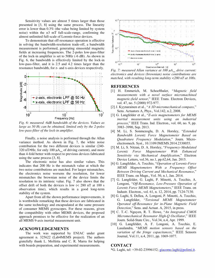
Finally, a noise analysis is performed through the Allan variance method. As shown in Fig. 7, the white noise contribution for the two different devices is similar (240-320 nT/•Hz, for only 100 μArms of driving current), and more than 4-fold better with respect to previous devices fabricated using the same process [3, 8].
The electronic noise has also similar values. This indicates that 200 Hz is the mismatch value at which the two noise contributions are matched. For larger mismatches, the electronics noise worsens the resolution, for lower mismatches the brownian noise of the device limits the resolution to its intrinsic value. Fig. 7 also shows that the offset drift of both the devices is low (< 280 nT at 100 s observation time), which results in a good long-term stability of the system.
Apart from all the shown performance improvements, it is worthwhile remarking that these devices are fabricated in the same technology and encapsulated at the same pressure of consumer MEMS gyroscopes. For these reasons, given the compatibility with other MEMS devices, the proposed approach promises to be effective for the realization of an all MEMS 9-axis inertial measurement unit.
ACKNOWLEDGEMENTS
The work was supported by ENIAC under grant agreement n. 325622 (Lab4MEMS project). The authors gratefully thank L. Molfetta and C. R. Marra for helping with boards preparation, and experimental measurements.
Fig. 7: measured Allan variance at 100 µArms drive current: electronics and devices (brownian) noise contributions are matched, with resulting long-term stability <280 nT at 100s.
REFERENCES [1] H. Emmerich, M. Schoefthaler, “Magnetic field
measurements with a novel surface micromachined magnetic-field sensor,” IEEE Trans. Electron Devices, vol. 47, no. 5 (2000) 972-977.
[2] J. Kyynarainen et al., “A 3D micromechanical compass,” Sens. Actuators A, Phys., Vol.142, n.2, 2008.
[3] G. Langfelder et al., “Z-axis magnetometers for MEMS inertial measurement units using an industrial process,” IEEE Trans. Ind. Electron., vol. 60, no. 9, pp. 3983–3990, Sep. 2013.
[4] M. Li, S. Sonmezoglu, D. A. Horsley, “Extended Bandwidth Lorentz Force Magnetometer Based on Quadrature Frequency Modulation,” Journ. Micro-electromech. Syst., 10.1109/JMEMS.2014.2330055.
[5] M. Li, S. Nitzan, D. A. Horsley, “Frequency-Modulated Lorentz Force Magnetometer With Enhanced Sensitivity via Mechanical Amplification,” Electron Device Letters, vol.36, no.1, pp.62,64, Jan. 2015.
[6] G. Langfelder, A. Tocchio, “Operation of Lorentz-Force MEMS Magnetometers With a Frequency Offset Between Driving Current and Mechanical Resonance,” IEEE Trans. on Magn., Vol. 50, n.1, Jan. 2014.
[7] G. Langfelder, G. Laghi, P. Minotti, A. Tocchio, A. Longoni, “Off-Resonance, Low-Pressure Operation of Lorentz Force MEMS Magnetometers,” IEEE Trans. on Industr. Electron., vol. 61, n. 12, 2014, pp. 7124-7130.
[8] G. Laghi, S. Dellea, A. Longoni, P. Minotti, A. Tocchio, G. Langfelder, “Torsional MEMS Magnetometer Operated off-Resonance for in-Plane Magnetic Field Detection,” Sens. and Actuat. A, 2015, in press.
[9] C. T.-C. Nguyen, R. T. Howe, “An Integrated CMOS Micromechanical Resonator High-Q Oscillator,” IEEE Journ. Solid-State Circ., Vol.34, n.4, Apr. 1999.
[10] G. Langfelder, A. F. Longoni, A. Tocchio, E. Lasalandra, “MEMS motion sensors based on the variation of the fringe capacitances,” IEEE Sensors Journal, Vol.11, n.4, 2011, pp. 1069-1077.
CONTACT *G. Laghi, tel: +39-02-23996152; [email protected].
Top Related