ZULIDZA BINTI ZULKAPLYstudentsrepo.um.edu.my/3907/1/1._Title_page,_abstract...ABSTRAK Pengeluaran...
16
EXCLUSIVE PHOTOPRODUCTION OF ψ(2S) IN ELECTRON-PROTON COLLISION AT HERA ZULIDZA BINTI ZULKAPLY FACULTY OF SCIENCE UNIVERSITY OF MALAYA KUALA LUMPUR 2012
Transcript of ZULIDZA BINTI ZULKAPLYstudentsrepo.um.edu.my/3907/1/1._Title_page,_abstract...ABSTRAK Pengeluaran...
EXCLUSIVE PHOTOPRODUCTION OF ψ(2S) IN ELECTRON-PROTON COLLISION AT HERA
ZULIDZA BINTI ZULKAPLY
FACULTY OF SCIENCEUNIVERSITY OF MALAYA
KUALA LUMPUR
2012
EXCLUSIVE PHOTOPRODUCTION OF ψ(2S) IN ELECTRON-PROTON COLLISION AT HERA
ZULIDZA BINTI ZULKAPLY
DISSERTATION SUBMITTED IN FULFILMENT OF THE REQUIREMENT FOR THE DEGREE OF
MASTER OF SCIENCE
DEPARTMENT OF PHYSICSFACULTY OF SCIENCE
UNIVERSITY OF MALAYAKUALA LUMPUR
2012
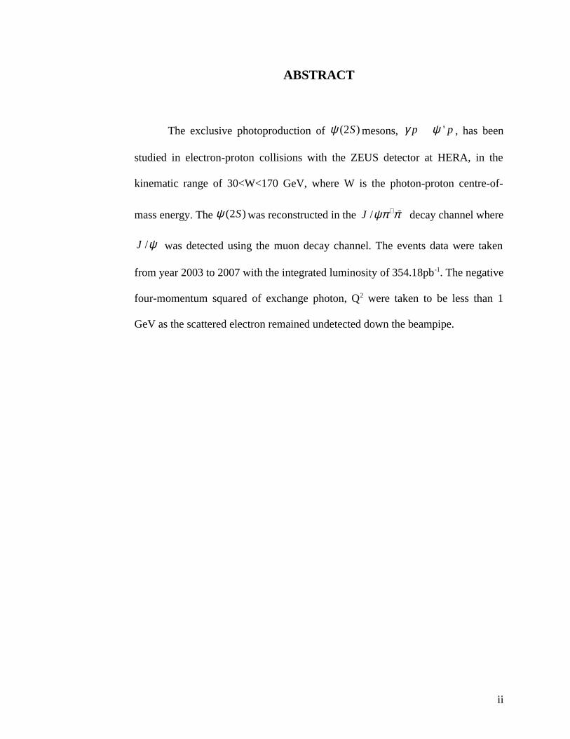
ABSTRACT
The exclusive photoproduction of (2 )Sψ mesons, 'p pγ ψ� , has been
studied in electron-proton collisions with the ZEUS detector at HERA, in the
kinematic range of 30<W<170 GeV, where W is the photon-proton centre-of-
mass energy. The (2 )Sψ was reconstructed in the /J ψπ π+ − decay channel where
/J ψ was detected using the muon decay channel. The events data were taken
from year 2003 to 2007 with the integrated luminosity of 354.18pb-1. The negative
four-momentum squared of exchange photon, Q2 were taken to be less than 1
GeV as the scattered electron remained undetected down the beampipe.
ii
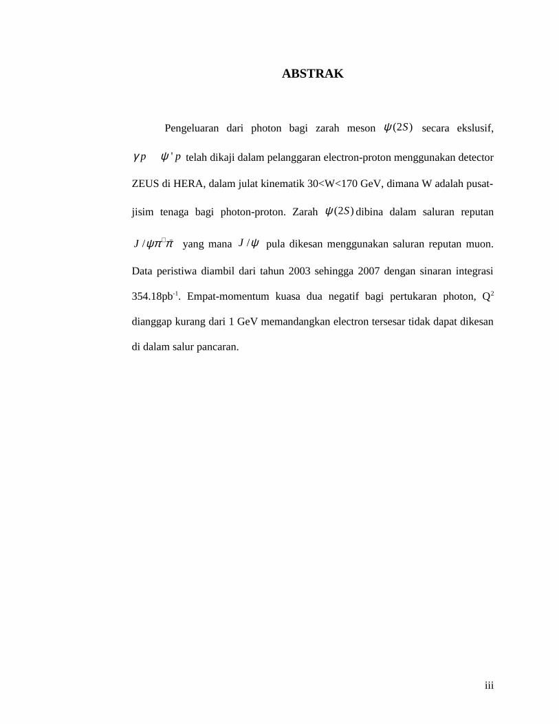
ABSTRAK
Pengeluaran dari photon bagi zarah meson (2 )Sψ secara ekslusif,
'p pγ ψ� telah dikaji dalam pelanggaran electron-proton menggunakan detector
ZEUS di HERA, dalam julat kinematik 30<W<170 GeV, dimana W adalah pusat-
jisim tenaga bagi photon-proton. Zarah (2 )Sψ dibina dalam saluran reputan
/J ψπ π+ − yang mana /J ψ pula dikesan menggunakan saluran reputan muon.
Data peristiwa diambil dari tahun 2003 sehingga 2007 dengan sinaran integrasi
354.18pb-1. Empat-momentum kuasa dua negatif bagi pertukaran photon, Q2
dianggap kurang dari 1 GeV memandangkan electron tersesar tidak dapat dikesan
di dalam salur pancaran.
iii
ACKNOWLEDGEMENT
First and foremost, thanks to Allah. I dedicate this thesis to my mother,
Puan Saerah Bt Mohd Salleh, for her help, love and patience. Next, to my
supervisor, Prof. Dr. Wan Ahmad Tajuddin Wan Abdullah, for all his guidance
and patience. Not forgettable I dedicate this work to my former co-supervisor,
Allahyarham Prof. Madya Dr. Burhanuddin Kamaluddin, ZEUS Collaboration
members, UM Physics Department, ZEUSMal colleagues, all my family
members, friends and everything inspired me. Last but not least, to Charlie. Thank
you all.
iv
TABLE OF CONTENTS
Abstract…………………………………………………………………...... ii
Abstrak……………………………………………………………………… iii
Acknowledgement………………………………………………………….. iv
Table of Contents…………………………………………………………… v
List of Figures………………………………………………………………. ix
List of Tables……………………………………………………………….. xiv
List of Symbols and Abbreviations………………………………………… xv
Chapter 1: Introduction
1.1 Photoproduction in Diffractive Scattering……………………………… 1
1.2 The Standard Model……………………………………………………. 3
1.3 Thesis Overview………………………………………………………... 7
Chapter 2: Electron-Proton Collision
2.1 Electron-proton collision at HERA…………………………………….. 9
2.2 Kinematics of electron-proton (ep) scattering………………………….. 10
2.3 Diffraction………………………………………………………………. 11
2.3.1 Regge Phenomenology………………………………………… 13
2.3.2 Vector Dominance Model (VDM)……………………………... 16
2.4 Photon-proton collisions………………………………………………... 18
2.5 Relation between ep and γ*p scattering………………………………… 20
2.6 Exclusive Vector Meson Photoproduction……………………………... 22
2.7 Acceptance and γp Cross Section………………………………………. 23
2.7.1 Acceptance Calculation on Monte Carlo (MC)………………... 23
2.7.2 γp Cross-Section Calculation…………………………………... 24
Chapter 3: Experimental Setup
v
3.1 ZEUS Experiment………………………………………………………. 26
3.2 HERA Collider…………………………………………………………. 26
3.3 ZEUS Detector………………………………………………………….. 29
3.4 Muon Detection System………………………………………………... 32
3.5 Central Tracking Detector (CTD)………………………………………. 35
3.6 Micro Vertex Detector (MVD)…………………………………………. 37
3.7 Forward and Rear Tracking Detectors (FTD, RTD)…………………… 38
3.8 Uranium Calorimeter (CAL)…………………………………………… 39
3.9 Monte Carlo Generator for Vector Meson……………………………… 43
Chapter 4: Tracking Effiency
4.1 Tracking concepts in detector…………………………………………... 45
4.1.1 Forward or fixed-target geometry and parameters…………….. 45
4.1.2 Collider detector geometry and parameters……………………. 49
4.2 Parameter estimation…………………………………………………… 51
4.2.1 Least squares estimation……………………………………….. 51
4.2.2 The Kalman Filter Technique………………………………….. 53
4.3 Typical tracking devices………………………………………………... 57
4.3.1 Single-coordinate measurement………………………………... 5
4.3.1.1 Silicon Strip detector………………………………….. 57
4.3.1.2 Drift chambers................................................................ 59
4.3.2 Stereo angle……………………………………………………. 62
4.3.3 Three-Dimentional (3D) measurement………………………… 64
4.4 Performance Evaluation............................................................................ 65
4.4.1 The reference set……………………………………………….. 65
4.4.2 Track finding efficiency……………………………………….. 67
4.4.3 Ghosts………………………………………………………….. 68
4.4.4 Clones………………………………………………………….. 68
4.4.5 Parameter resolution…………………………………………… 69
vi
Chapter 5: Data Analysis and Results
5.1 ORANGE (Overlying Routine Analysis of Ntuple Generation)……….. 70
5.2 Data Analysis Software………………………………………………… 72
5.2.1 Physics Analysis Worstation (PAW)…………………………... 72
5.2.2 ROOT………………………………………………………….. 75
5.2.3 Zeus Event Visualization (ZEVIS)…………………………….. 77
5.3 Grand Reprocess (GR) Data……………………………………………. 78
5.4 Monte Carlo (MC) Data………………………………………………… 78
5.5 'ψ Photoproduction (PHP)……………………………………………... 82
5.6 Results…………………………………………………………………... 85
Chapter 6: Conclusion and Discussion 88
Bibliography………………………………………………………………... 91
vii
LIST OF FIGURES
Figure 1.1: The picture shows the diagram of )2( Sψ photoproduction in
electron-proton collision where the scattered electron and proton escape
undetected in the beampipe.
Figure 1.2: The diagram of the Standard Model (SM) of elementary particles
Figure 1.3: The Standard Model development in historical perspective. The idea
of quarks as the constituents of matter and their subsequent experimental
confirmation are shown.
Figure 2.1: Feynman diagram of ep scattering.
Figure 2.2: The classification of diffractive processes: (a) Elastic, (b) Single
diffraction, (c) Double diffraction.
Figure 2.3: Total cross section measured in hadronic scattering as a function of
centre-of-mass energy for (a) ,pp pp and (b) pπ � scattering. The total cross-
sections drop at energy s < 10 GeV and increase consistently for higher energy
level with the form of 0.08sσ � .
viii
Figure 2.4: The total cross-section of photon-hadron scattering, totσ , as a
function of different W2 and Q2.
Figure 2.5: The schematic presentation of energy flow in non-diffractive and
diffractive event with large rapidity gap at HERA.
Figure 2.6: Schematic diagram of VM production.
Figure 3.1: The aerial view of HERA showing the ring location of the
accelerators.
Figure 3.2: The picture shows the direction of electron and proton injection
flows. The red arrow represents the electron and the blue arrows represent the
proton.
Figure 3.3: The picture shows a 3-dimentional view of a ZEUS detector, its main
components and the electron proton directions. The circled area indicates the
interaction point of the electron proton collision.
Figure 3.4: The picture shows the coordinate system of the ZEUS detector.
Figure 3.5 : Cross section of the ZEUS detector in x − y plane
ix
Figure 3.6: Cross section of the ZEUS detector in z − y plane
Figure 3.7 : 3D structure of BRMUON
Figure 3.8 : Cross section of FMUON
Figure 3.9: Layout of a CTD octant. The superlayers are numbered and the stereo
angles of their sense wires are shown.
Figure 3.10: Cross sections of the MVD along the beam pipe (left) and in the x-y
plane (right).
Figure 3.11: The Layout of the FTD drift chambers in (left) overall view and
(right) view of the 3 layers inside of one of the chambers.
Figure 3.12: (left) a view of the tracking detectors, in the forward area the four
tracking detectors planes are shown, which were replaced with two straw-tube
tracker (STT) wheels, (right) the angular coverage of the STT compared to the
CTD and forward MVD wheels.
Figure 3.13: Cross section of the ZEUS CAL in the y-z plane.
Figure 3.14: View of an FCAL module. The towers containing the EMC and
HAC sections are shown.
x
Figure 4.1 : Typical geometry of a forward spectrometer
Figure 4.2: Typical setup of a cylindrical or collider detector.
Figure 4.3 : Lower half barrel of the Zeus micro-vertex detector
Figure 4.4: Schematic view of a drift chamber cell. The closed circle indicates
wires, with sense wires in the middle and field wires on the outside. The long and
thick arrow represents a trajectory of a particle while the small arrows denote
primary ionization charges drifting towards the sense wire.
Figure 4.5: Event display from the ZEUS central tracking detector where the
closeup view given in the square. The blue line is the trajectory and the red dot is
the drift distance end points on both side of the corresponding wire.
Figure 4.6 : Top left : The real hit points with two stereo views on x plane (0°)
and u plane (45°). Top right : Single view on x and u plane with two ghost points
in blue. Bottom left : Ambiguity hits observed on x and u plane.
Figure 4.7 : TPC of the STAR experiment.
xi
Figure 5.1: Example of initial page of control cards which show selection of
several routines applicable in ORANGE.
Figure 5.2: PAW and its components
Figure 5.3: ROOT framework directories
Figure 5.4: Zevis display of trimuon event. One of the muons is identified in the
outer barrel muon chambers and in BAC (both hits and pads), embedded into a
jet. The second is seen in BAC only (pads only).The third is seen in the forward
muon chambers (clean long track starting in the inner chambers) and in the
forward BAC, embedded into a forward jet.
Figure 5.6: Figure shows the reconstructed mass of 'ψ generated by PAW using
the simulated ZEUS MC data for −+→ πψπψ /' J decay channel.
Figure 5.7: Figure shows the reconstructed mass of 'ψ generated by PAW using
the ZEUS GR data for −+−+→ ππµµψ ' decay channel in 2003-2007 events.
Figure 5.8: Cross section of 'ψ in e-p collision at HERA for ZEUS GR data in
2003-2007 events.
Figure 6.1: The cross section for 'ψ at ZEUS highlighted in yellow, in
comparison with H1 experiment and other vector mesons.
xii

LIST OF TABLES
Table 1.0: Rough comparison between PAW and ROOT.
Table 2.0: Size of GR ntuple for v02 and v04.
Table 3.0: Properties of 'ψ photoproduction with number of 'ψ particles,
Nψ(2S), acceptance, A, photon flux, Ф and the cross section, σ, in different W
range.
xiii
LIST OF SYMBOLS AND ABBREVIATIONS
Ψ’ / ψ (2S) Psi particle
J/ ψ J/psi particle
μ Muon particle
π Pi particle
2D 2-Dimensional
3D 3-Dimensional
BMUON Barrel Muon Detector
BNL Brookhaven National Laboratory
BRMUON Barrel Rear Muon Detector
CAL Calorimeter
CC Charged Current
CTD Central Tracking Detector
DESY Deutch Elektronen Synchotron
DIS Deep Inelastic Scattering
FMUON Forward Muon
FTD Forward Tracking Detector
GMUON Global Muon System
GR Grand Reprocess
HERA Hadron Electron Ring Accelerator
MC Monte Carlo
MIP Minimum ionizing particle
MVD Micro Vertex Detector
NC Neutral Current
ORANGE Overlying Routine Analysis of Ntuple Generation
PAW Physics Analysis Workstation
PHP Photoproduction
xiv
QCD Quantum Chromodynamics
QED Quantum Electrodynamics
RMUON Rear Muon Detector
RTD Rear Tracking Detector
SLAC Stanford Linear Accelerator Center
SM Standard Model
VM / VMs Vector Meson / Vector Mesons
ZEVIS Zeus Event Displays
xv