
Xtra Long Life 10 million cycles USB/Ethernet RF Switch Matrix RC … · Page 2 of 9 Mini-Circuits...
9
Page 1 of 9 Mini-Circuits ® www.minicircuits.com P.O. Box 35166, Brooklyn, NY 11235-0003 (718) 934-4500 [email protected] RC-2SP4T-A18 USB/Ethernet RF Switch Matrix Xtra Long Life 10 million cycles 50Ω DC to 18 GHz Product Overview Mini-Circuits’ RC-2SP4T-A18 is a general purpose RF switch matrix controlled via either USB or Ethernet-TCP/IP (supports HTTP and Telnet protocols). The model contains two electromechanical SP4T, absorptive fail-safe RF switches constructed in break-before-make configuration and powered by +24VDC, with switching time of 25 ms typical. The RF switches operate over a wide frequency band from DC to 18 GHz, have low insertion loss (0.2 dB typical) and high isolation (85 dB typical), making the switch matrix perfectly suitable for a wide variety of RF applications. The RC-2SP4T-A18 is constructed in a compact, rugged metal case (5.5” x 6.0” x 2.25”) with 10 SMA (F) connectors (COM and ports 1 to 4, for each switch), USB type B port, standard RJ45 network socket and DC power input. Full software support is provided and can be downloaded from our website any time at https://www.minicircuits.com/softwaredownload/rfswitchcontroller.html. The package includes our user-friendly GUI application for Windows and a full API with programming instructions for Windows and Linux environments (both 32-bit and 64-bit systems). Also included is a 2.7 ft USB cable and AC/DC power adapter. Longer USB cables, Ethernet cables and a mounting bracket are available as optional accessories. The Big Deal •Dual mechanical SP4T switch box • High reliability, 10 million switch cycles • 20W power rating (cold switching) • High isolation, 85 dB typ Software Package Key Features Feature Advantages Ethernet-TCP/IP- HTTP and Telnet Protocols (Supports DHCP and Static IP) The RC-2SP4T-A18 switch matrix can be controlled from any Windows ® , Mac ® , or Linux ® computer, or even a mobile device with a network connection and Ethernet-TCP/IP (HTTP or Telnet protocols) support. Using a VPN would allow remote control from anywhere in the world. USB HID (Human Interface Device) User may also control the switch matrix via USB connection. Plug-and-Play, no driver required. Compatible with Windows ® or Linux ® operating systems using 32 and 64 bit architecture. RF SP4T absorptive electromechanical switch Wideband (DC to 18 GHz) with low insertion loss (0.2 dB typ.), very high isolation (85 dB typ.), and high power rating (20W cold switching). Switch Cycle Counters Allows user to monitor the exact usage and plan test requirements accordingly. Break-before-make configuration Prevents the momentary connection of the old and new signal paths and reduces transient phenomena. Model No. Description Qty. RC-2SP4T-A18 USB/Ethernet RF Switch 1 Included Accessories AC/DC-24-3W1 AC/DC 24V Adapter 1 CBL-3W1-XX AC Power Cord (see Ordering Information) 1 USB-CBL-AB-3+ 2.7 ft USB cable 1 RoHS Compliant See our web site for RoHS Compliance methodologies and qualifications Case Style: MR1937 Trademarks: Windows is a registered trademark of Microsoft Corporation in the United States and other countries. Linux is a registered trademark of Linus Torvalds. Pentium is a registered trademark of Intel Corporation. Mac is a registered trademark of Apple Corporation in the United States and other countries. Neither Mini-Circuits nor the Mini-Circuits RC-2SP4T-A18 are affiliated with or endorsed by the owners of the above referenced trademarks Mini-Circuits and the Mini-Circuits logo are registered trademarks of Scientific Components Corporation. Patents: protected by US Patents 5,272,458; 6,414,577; 6,650,210; 7,633,361 and 7,843,289 Rev. C M158756 RC-2SP4T-A18 RAV 171017 Applications • R&D • Automated Test equipment • Controlling RF signal paths
Transcript of Xtra Long Life 10 million cycles USB/Ethernet RF Switch Matrix RC … · Page 2 of 9 Mini-Circuits...
Page 1 of 9Mini-Circuits®
www.minicircuits.com P.O. Box 35166, Brooklyn, NY 11235-0003 (718) 934-4500 [email protected]
RC-2SP4T-A18USB/Ethernet RF Switch MatrixXtra Long Life 10 million cycles
50Ω DC to 18 GHz
Product OverviewMini-Circuits’ RC-2SP4T-A18 is a general purpose RF switch matrix controlled via either USB or Ethernet-TCP/IP (supportsHTTP and Telnet protocols). The model contains two electromechanical SP4T, absorptive fail-safe RF switches constructed inbreak-before-make configuration and powered by +24VDC, with switching time of 25 ms typical. The RF switches operate overa wide frequency band from DC to 18 GHz, have low insertion loss (0.2 dB typical) and high isolation (85 dB typical), making theswitch matrix perfectly suitable for a wide variety of RF applications.
The RC-2SP4T-A18 is constructed in a compact, rugged metal case (5.5” x 6.0” x 2.25”) with 10 SMA (F) connectors (COM andports 1 to 4, for each switch), USB type B port, standard RJ45 network socket and DC power input. Full software support is provided and can be downloaded from our website any time at https://www.minicircuits.com/softwaredownload/rfswitchcontroller.html. The package includes our user-friendly GUI application for Windows and a full API with programming instructions for Windows and Linux environments (both 32-bit and 64-bit systems). Also included is a 2.7 ft USB cable and AC/DC power adapter. Longer USB cables, Ethernet cables and a mounting bracket are available as optional accessories.
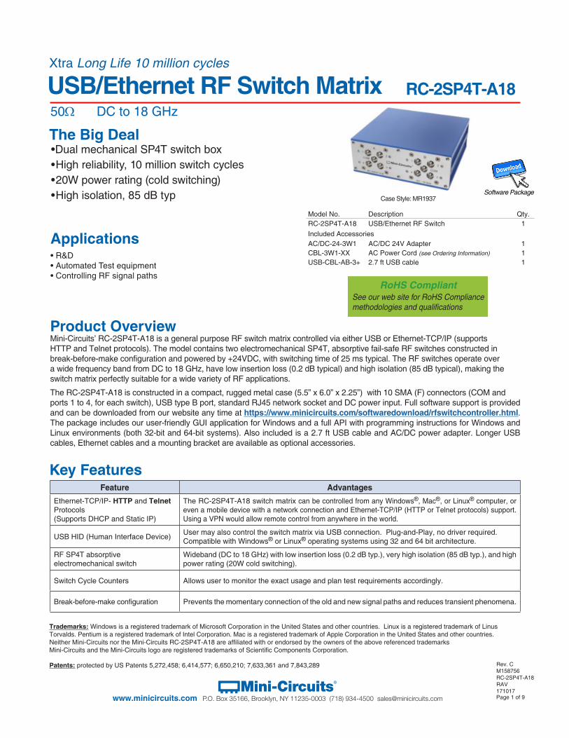
The Big Deal•Dual mechanical SP4T switch box• High reliability, 10 million switch cycles• 20W power rating (cold switching)• High isolation, 85 dB typ Software Package
Key FeaturesFeature Advantages
Ethernet-TCP/IP- HTTP and Telnet Protocols (Supports DHCP and Static IP)
The RC-2SP4T-A18 switch matrix can be controlled from any Windows®, Mac®, or Linux® computer, or even a mobile device with a network connection and Ethernet-TCP/IP (HTTP or Telnet protocols) support. Using a VPN would allow remote control from anywhere in the world.
USB HID (Human Interface Device) User may also control the switch matrix via USB connection. Plug-and-Play, no driver required. Compatible with Windows® or Linux® operating systems using 32 and 64 bit architecture.
RF SP4T absorptive electromechanical switch
Wideband (DC to 18 GHz) with low insertion loss (0.2 dB typ.), very high isolation (85 dB typ.), and high power rating (20W cold switching).
Switch Cycle Counters Allows user to monitor the exact usage and plan test requirements accordingly.
Break-before-make configuration Prevents the momentary connection of the old and new signal paths and reduces transient phenomena.
Model No. Description Qty.RC-2SP4T-A18 USB/Ethernet RF Switch 1Included AccessoriesAC/DC-24-3W1 AC/DC 24V Adapter 1CBL-3W1-XX AC Power Cord (see Ordering Information) 1USB-CBL-AB-3+ 2.7 ft USB cable 1
RoHS CompliantSee our web site for RoHS Compliance methodologies and qualifications
Case Style: MR1937
Trademarks: Windows is a registered trademark of Microsoft Corporation in the United States and other countries. Linux is a registered trademark of Linus Torvalds. Pentium is a registered trademark of Intel Corporation. Mac is a registered trademark of Apple Corporation in the United States and other countries. Neither Mini-Circuits nor the Mini-Circuits RC-2SP4T-A18 are affiliated with or endorsed by the owners of the above referenced trademarksMini-Circuits and the Mini-Circuits logo are registered trademarks of Scientific Components Corporation.
Patents: protected by US Patents 5,272,458; 6,414,577; 6,650,210; 7,633,361 and 7,843,289 Rev. CM158756RC-2SP4T-A18RAV171017
Applications• R&D • Automated Test equipment• Controlling RF signal paths
Page 2 of 9Mini-Circuits®
www.minicircuits.com P.O. Box 35166, Brooklyn, NY 11235-0003 (718) 934-4500 [email protected]
RC-2SP4T-A18USB/Ethernet RF Switch Matrix
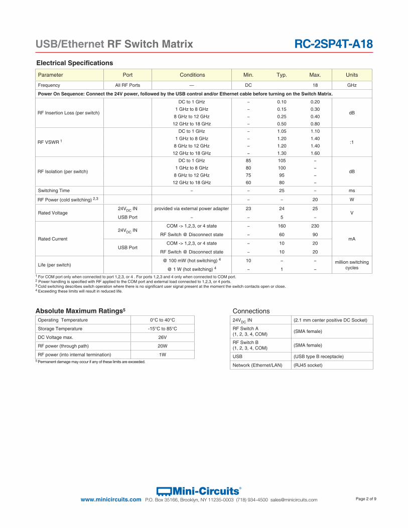
Parameter Port Conditions Min. Typ. Max. Units
Frequency All RF Ports — DC 18 GHz
Power On Sequence: Connect the 24V power, followed by the USB control and/or Ethernet cable before turning on the Switch Matrix.
RF Insertion Loss (per switch)
DC to 1 GHz − 0.10 0.20
dB1 GHz to 8 GHz − 0.15 0.30
8 GHz to 12 GHz − 0.25 0.40
12 GHz to 18 GHz − 0.50 0.80
RF VSWR 1
DC to 1 GHz − 1.05 1.10
:11 GHz to 8 GHz − 1.20 1.40
8 GHz to 12 GHz − 1.20 1.40
12 GHz to 18 GHz − 1.30 1.60
RF Isolation (per switch)
DC to 1 GHz 85 105 −
dB1 GHz to 8 GHz 80 100 −
8 GHz to 12 GHz 75 95 −
12 GHz to 18 GHz 60 80 −
Switching Time − − 25 − ms
RF Power (cold switching) 2,3 − − 20 W
Rated Voltage 24VDC IN provided via external power adapter 23 24 25
VUSB Port − − 5 −
Rated Current
24VDC INCOM -> 1,2,3, or 4 state − 160 230
mARF Switch @ Disconnect state − 60 90
USB PortCOM -> 1,2,3, or 4 state − 10 20
RF Switch @ Disconnect state − 10 20
Life (per switch) @ 100 mW (hot switching) 4 10 − − million switching
cycles@ 1 W (hot switching) 4 − 1 −
Electrical Specifications
1 For COM port only when connected to port 1,2,3, or 4 . For ports 1,2,3 and 4 only when connected to COM port. 2 Power handling is specified with RF applied to the COM port and external load connected to 1,2,3, or 4 ports.3 Cold switching describes switch operation where there is no significant user signal present at the moment the switch contacts open or close.4 Exceeding these limits will result in reduced life.
Connections24VDC IN (2.1 mm center positive DC Socket)
RF Switch A (1, 2, 3, 4, COM) (SMA female)
RF Switch B (1, 2, 3, 4, COM) (SMA female)
USB (USB type B receptacle)
Network (Ethernet/LAN) (RJ45 socket)
Absolute Maximum Ratings5
Operating Temperature 0°C to 40°C
Storage Temperature -15°C to 85°C
DC Voltage max. 26V
RF power (through path) 20W
RF power (into internal termination) 1W5 Permanent damage may occur if any of these limits are exceeded.
Page 3 of 9Mini-Circuits®
www.minicircuits.com P.O. Box 35166, Brooklyn, NY 11235-0003 (718) 934-4500 [email protected]
RC-2SP4T-A18USB/Ethernet RF Switch Matrix
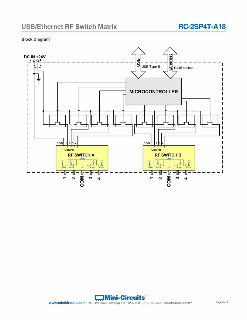
Block Diagram
DC IN +24V- +
CO
M21 43
COM 1 2 3 4
MICROCONTROLLER
USB
Ethe
rnet
RJ45 socketUSB Type B
Control
RF SWITCH A
- + + + +
150Ω
250Ω
350Ω
450Ω
COM
CO
M21 43
COM 1 2 3 4
Control
RF SWITCH B
- + + + +
150Ω
250Ω
350Ω
450Ω
COM
Page 4 of 9Mini-Circuits®
www.minicircuits.com P.O. Box 35166, Brooklyn, NY 11235-0003 (718) 934-4500 [email protected]
RC-2SP4T-A18USB/Ethernet RF Switch Matrix
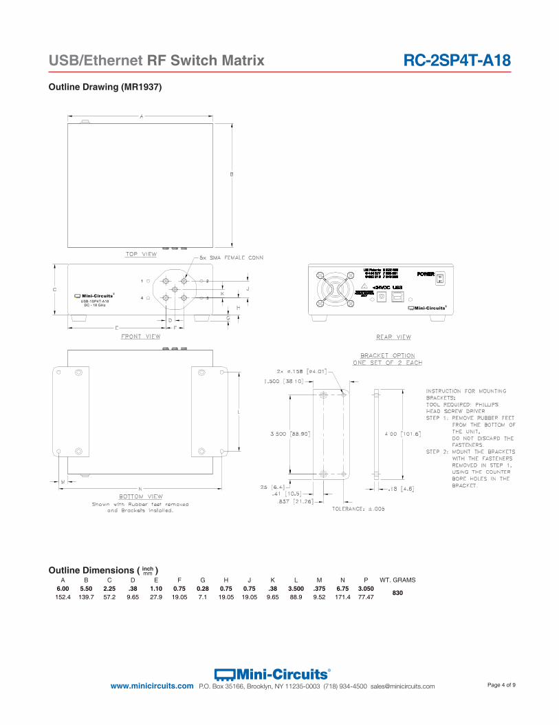
Outline Drawing (MR1937)
98-MR Rev. E 09.30.16 M158168 File: 98-MR Sheet 1 of 3 This document and its contents are the property of Mini-Circuits
Case Style MR
Outline Dimensions MR1778
Mini-Circuits
DC - 18 GHzUSB-1SP4T-A18
Mini-Circuits
1 2
4 3
CASE# A B C D E F G H J K L M N WT. GRAMS
MR1778 6.00 (152.4)
5.50 (139.7)
2.25 (57.2)
.38 (9.65)
4.05 (102.9)
.75 (19.05)
.28 (7.1)
.75 (19.05)
.75 (19.05)
.38 (9.65)
3.500 (88.9)
.375 (9.52)
6.75 (171.4) 830
Dimensions are in inches (mm). Tolerances: 2PL. +/- .03; 3PL. +/- .015
Notes: 1. Case and Bracket material: Aluminum Alloy. 2. Finish: For Case- Powder coating. Color: Blue, For Bracket- Clear Chemical conversion coating.
inchmmOutline Dimensions ( )
A B C D E F G H J K L M N P WT. GRAMS6.00 5.50 2.25 .38 1.10 0.75 0.28 0.75 0.75 .38 3.500 .375 6.75 3.050
830152.4 139.7 57.2 9.65 27.9 19.05 7.1 19.05 19.05 9.65 88.9 9.52 171.4 77.47
Page 5 of 9Mini-Circuits®
www.minicircuits.com P.O. Box 35166, Brooklyn, NY 11235-0003 (718) 934-4500 [email protected]
RC-2SP4T-A18USB/Ethernet RF Switch Matrix
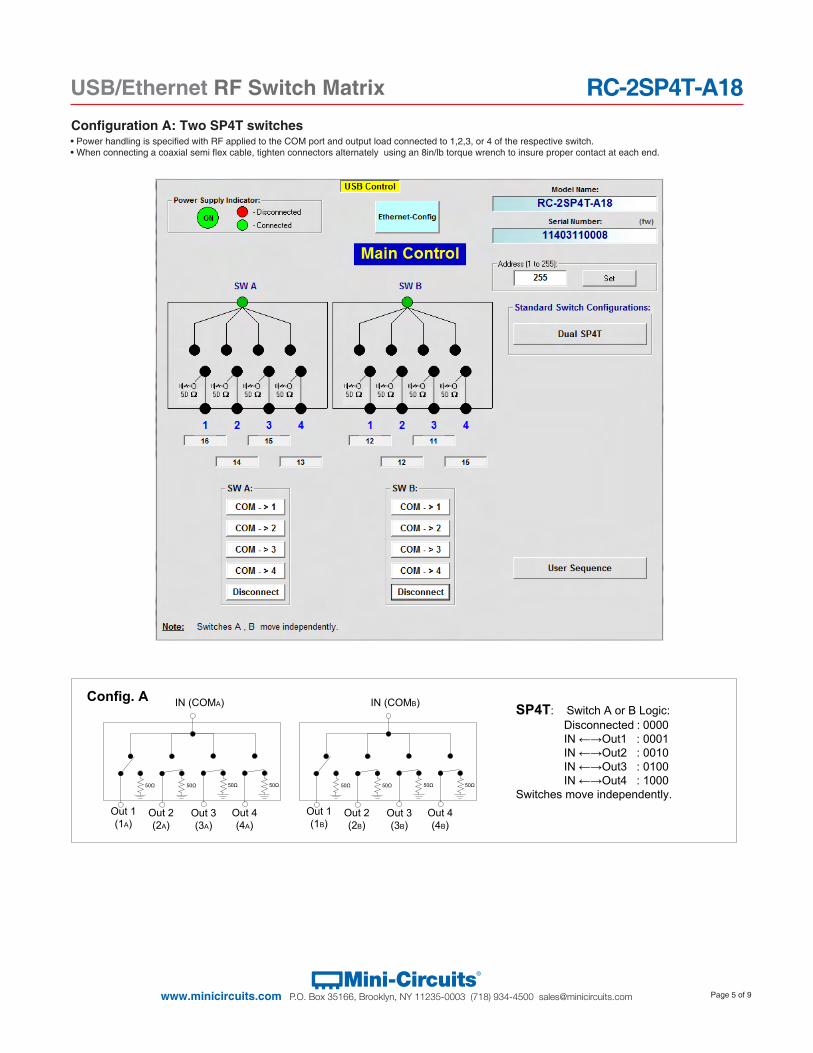
• Power handling is specified with RF applied to the COM port and output load connected to 1,2,3, or 4 of the respective switch.• When connecting a coaxial semi flex cable, tighten connectors alternately using an 8in/lb torque wrench to insure proper contact at each end.
Configuration A: Two SP4T switches
Config. ASP4T: Switch A or B Logic:
Disconnected : 0000 IN ←→Out1 : 0001 IN ←→Out2 : 0010 IN ←→Out3 : 0100 IN ←→Out4 : 1000
Switches move independently.
IN (COMA)
Out 1(1A)
Out 4(4A)
Out 2(2A)
Out 3(3A)
50Ω 50Ω 50Ω 50Ω
IN (COMB)
Out 1(1B)
Out 4(4B)
Out 2(2B)
Out 3(3B)
50Ω 50Ω 50Ω 50Ω
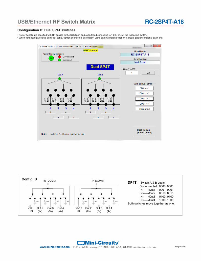
Config. BDP4T: Switch A & B Logic:
Disconnected : 0000, 0000 IN ←→Out1 : 0001, 0001 IN ←→Out2 : 0010, 0010 IN ←→Out3 : 0100, 0100 IN ←→Out4 : 1000, 1000
Both switches move together as one.
IN (COMA)
Out 1(1A)
Out 4(4A)
Out 2(2A)
Out 3(3A)
50Ω 50Ω 50Ω 50Ω
IN (COMB)
Out 1(1B)
Out 4(4B)
Out 2(2B)
Out 3(3B)
50Ω 50Ω 50Ω 50Ω
Page 6 of 9Mini-Circuits®
www.minicircuits.com P.O. Box 35166, Brooklyn, NY 11235-0003 (718) 934-4500 [email protected]
RC-2SP4T-A18USB/Ethernet RF Switch Matrix
• Power handling is specified with RF applied to the COM port and output load connected to 1,2,3, or 4 of the respective switch.• When connecting a coaxial semi flex cable, tighten connectors alternately using an 8in/lb torque wrench to insure proper contact at each end.
Configuration B: Dual SP4T switches
Figure 3 – Dual SP4T Control Screen
Config. ASP4T: Switch A or B Logic:
Disconnected : 0000 IN ←→Out1 : 0001 IN ←→Out2 : 0010 IN ←→Out3 : 0100 IN ←→Out4 : 1000
Switches move independently.
IN (COMA)
Out 1(1A)
Out 4(4A)
Out 2(2A)
Out 3(3A)
50Ω 50Ω 50Ω 50Ω
IN (COMB)
Out 1(1B)
Out 4(4B)
Out 2(2B)
Out 3(3B)
50Ω 50Ω 50Ω 50Ω
Config. BDP4T: Switch A & B Logic:
Disconnected : 0000, 0000 IN ←→Out1 : 0001, 0001 IN ←→Out2 : 0010, 0010 IN ←→Out3 : 0100, 0100 IN ←→Out4 : 1000, 1000
Both switches move together as one.
IN (COMA)
Out 1(1A)
Out 4(4A)
Out 2(2A)
Out 3(3A)
50Ω 50Ω 50Ω 50Ω
IN (COMB)
Out 1(1B)
Out 4(4B)
Out 2(2B)
Out 3(3B)
50Ω 50Ω 50Ω 50Ω
Page 7 of 9Mini-Circuits®
www.minicircuits.com P.O. Box 35166, Brooklyn, NY 11235-0003 (718) 934-4500 [email protected]
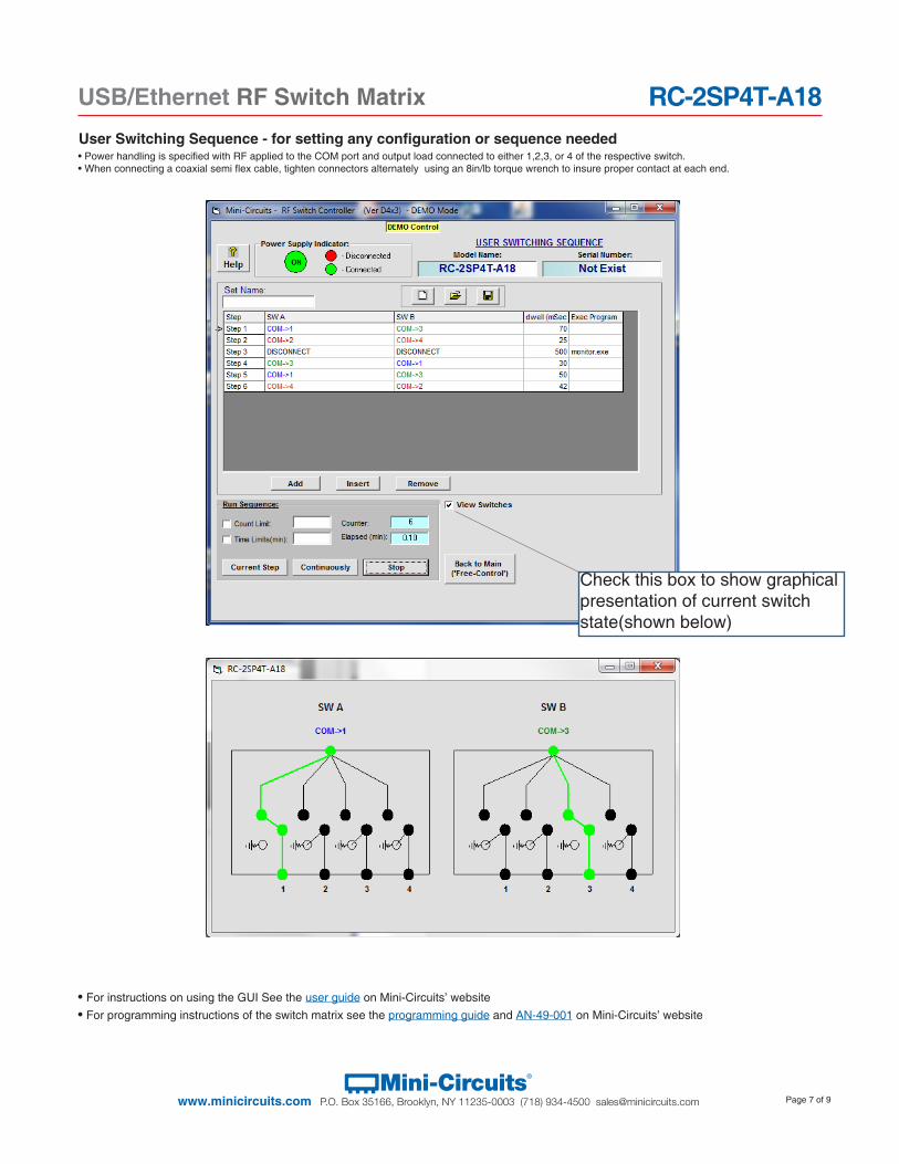
RC-2SP4T-A18USB/Ethernet RF Switch MatrixUser Switching Sequence - for setting any configuration or sequence needed• Power handling is specified with RF applied to the COM port and output load connected to either 1,2,3, or 4 of the respective switch.• When connecting a coaxial semi flex cable, tighten connectors alternately using an 8in/lb torque wrench to insure proper contact at each end.
• For instructions on using the GUI See the user guide on Mini-Circuits’ website• For programming instructions of the switch matrix see the programming guide and AN-49-001 on Mini-Circuits’ website
Figure 4 – User Sequence Screen
Figure 5 – User Sequence Switches Graphics Screen
Check this box to show graphical presentation of current switch state(shown below)
Page 8 of 9Mini-Circuits®
www.minicircuits.com P.O. Box 35166, Brooklyn, NY 11235-0003 (718) 934-4500 [email protected]
RC-2SP4T-A18USB/Ethernet RF Switch Matrix
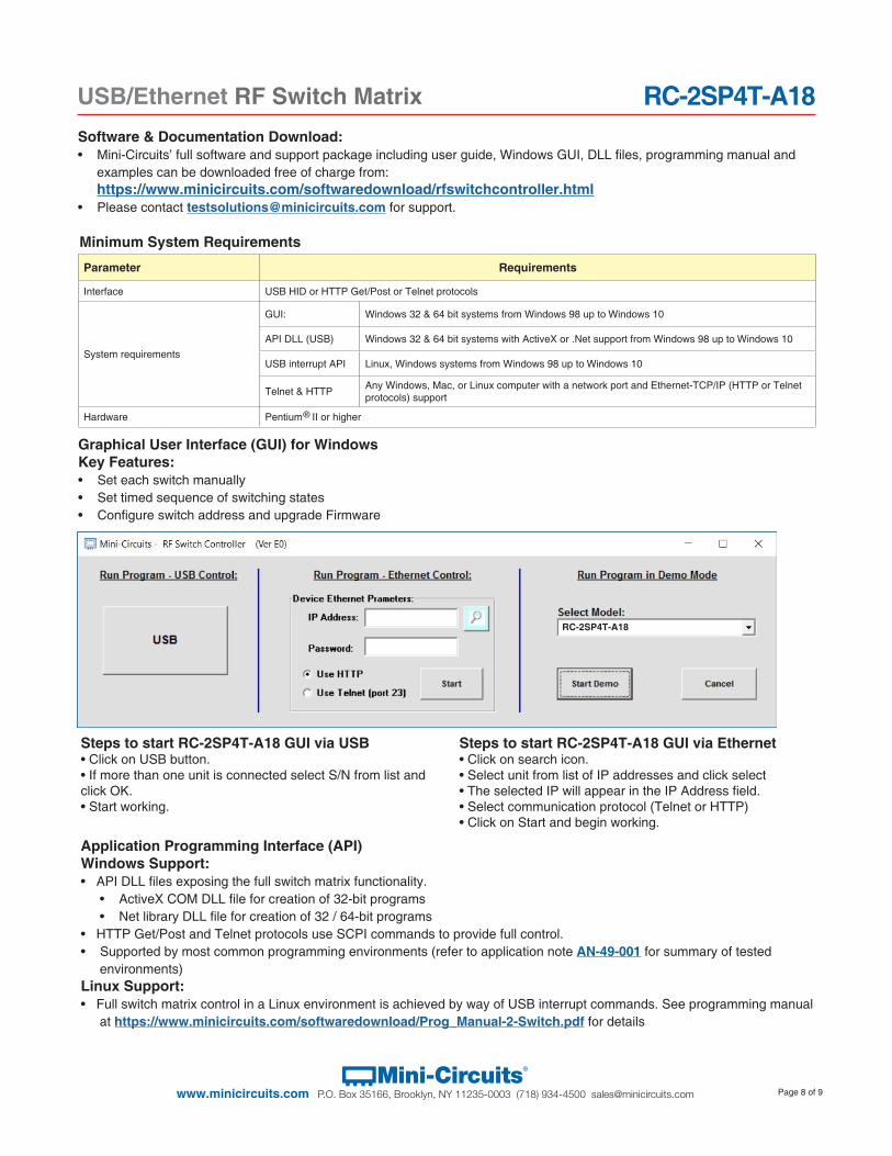
Minimum System Requirements
Parameter Requirements
Interface USB HID or HTTP Get/Post or Telnet protocols
System requirements
GUI: Windows 32 & 64 bit systems from Windows 98 up to Windows 10
API DLL (USB) Windows 32 & 64 bit systems with ActiveX or .Net support from Windows 98 up to Windows 10
USB interrupt API Linux, Windows systems from Windows 98 up to Windows 10
Telnet & HTTP Any Windows, Mac, or Linux computer with a network port and Ethernet-TCP/IP (HTTP or Telnet protocols) support
Hardware Pentium ® II or higher
Software & Documentation Download:• Mini-Circuits’ full software and support package including user guide, Windows GUI, DLL files, programming manual and
examples can be downloaded free of charge from: https://www.minicircuits.com/softwaredownload/rfswitchcontroller.html
• Please contact [email protected] for support.
Application Programming Interface (API)Windows Support:• API DLL files exposing the full switch matrix functionality.
• ActiveX COM DLL file for creation of 32-bit programs • Net library DLL file for creation of 32 / 64-bit programs
• HTTP Get/Post and Telnet protocols use SCPI commands to provide full control. • Supported by most common programming environments (refer to application note AN-49-001 for summary of tested
environments)Linux Support:• Full switch matrix control in a Linux environment is achieved by way of USB interrupt commands. See programming manual
at https://www.minicircuits.com/softwaredownload/Prog_Manual-2-Switch.pdf for details
Graphical User Interface (GUI) for WindowsKey Features:• Set each switch manually• Set timed sequence of switching states• Configure switch address and upgrade Firmware
Steps to start RC-2SP4T-A18 GUI via USB• Click on USB button.• If more than one unit is connected select S/N from list andclick OK.• Start working.
Steps to start RC-2SP4T-A18 GUI via Ethernet• Click on search icon.• Select unit from list of IP addresses and click select• The selected IP will appear in the IP Address field.• Select communication protocol (Telnet or HTTP)• Click on Start and begin working.
RC-2SP4T-A18
Page 9 of 9Mini-Circuits®
www.minicircuits.com P.O. Box 35166, Brooklyn, NY 11235-0003 (718) 934-4500 [email protected]
RC-2SP4T-A18USB/Ethernet RF Switch Matrix
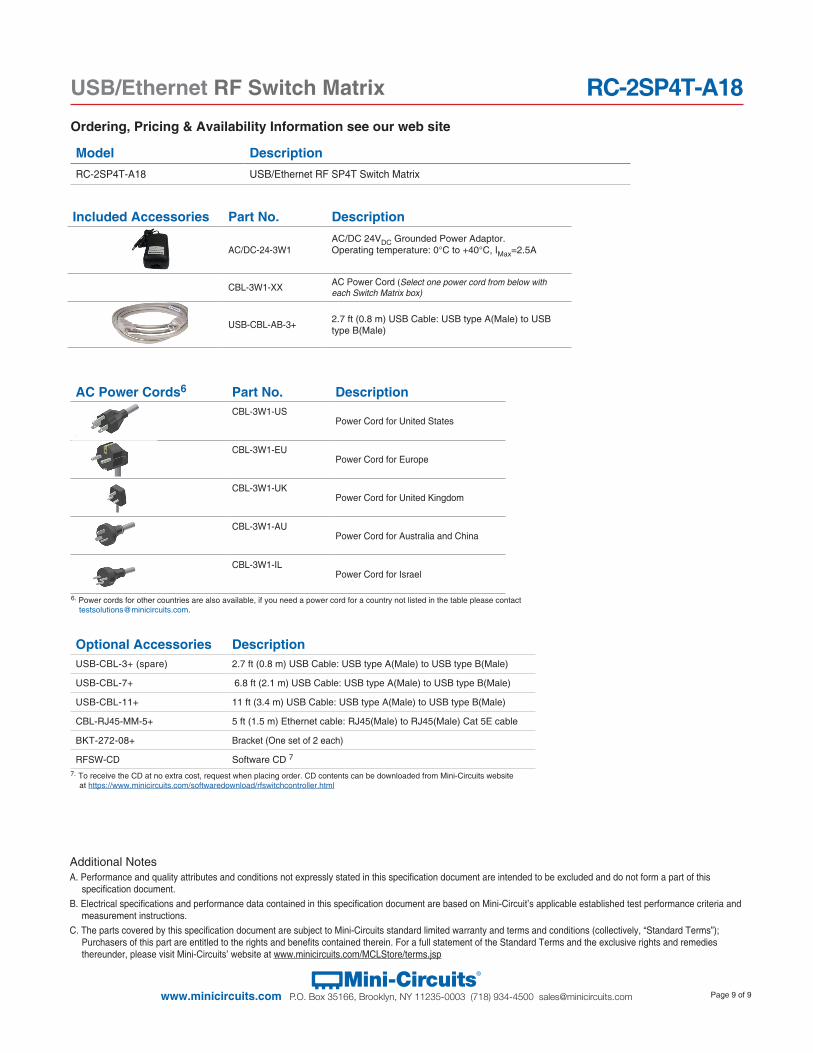
Ordering, Pricing & Availability Information see our web site
Additional NotesA. Performance and quality attributes and conditions not expressly stated in this specification document are intended to be excluded and do not form a part of this
specification document. B. Electrical specifications and performance data contained in this specification document are based on Mini-Circuit’s applicable established test performance criteria and
measurement instructions. C. The parts covered by this specification document are subject to Mini-Circuits standard limited warranty and terms and conditions (collectively, “Standard Terms”);
Purchasers of this part are entitled to the rights and benefits contained therein. For a full statement of the Standard Terms and the exclusive rights and remedies thereunder, please visit Mini-Circuits’ website at www.minicircuits.com/MCLStore/terms.jsp
Model DescriptionRC-2SP4T-A18 USB/Ethernet RF SP4T Switch Matrix
Included Accessories Part No. Description
AC/DC-24-3W1AC/DC 24VDC Grounded Power Adaptor. Operating temperature: 0°C to +40°C, IMax=2.5A
CBL-3W1-XX AC Power Cord (Select one power cord from below with each Switch Matrix box)
USB-CBL-AB-3+ 2.7 ft (0.8 m) USB Cable: USB type A(Male) to USB type B(Male)
6. Power cords for other countries are also available, if you need a power cord for a country not listed in the table please contact [email protected].
AC Power Cords6 Part No. DescriptionCBL-3W1-US
Power Cord for United States
CBL-3W1-EUPower Cord for Europe
CBL-3W1-UKPower Cord for United Kingdom
CBL-3W1-AUPower Cord for Australia and China
CBL-3W1-ILPower Cord for Israel
Optional Accessories DescriptionUSB-CBL-3+ (spare) 2.7 ft (0.8 m) USB Cable: USB type A(Male) to USB type B(Male)
USB-CBL-7+ 6.8 ft (2.1 m) USB Cable: USB type A(Male) to USB type B(Male)
USB-CBL-11+ 11 ft (3.4 m) USB Cable: USB type A(Male) to USB type B(Male)
CBL-RJ45-MM-5+ 5 ft (1.5 m) Ethernet cable: RJ45(Male) to RJ45(Male) Cat 5E cable
BKT-272-08+ Bracket (One set of 2 each)
RFSW-CD Software CD 7
7. To receive the CD at no extra cost, request when placing order. CD contents can be downloaded from Mini-Circuits website at https://www.minicircuits.com/softwaredownload/rfswitchcontroller.html

![arXiv:1612.07457v1 [hep-ph] 22 Dec 2016 Keywords: QCD, AdS ... · 2 New York City College of Technology, Brooklyn, NY 11201, USA , and 3 Union College, Schenectady NY, 12308, USA](https://static.fdocument.org/doc/165x107/5f2f45e851f4992749507298/arxiv161207457v1-hep-ph-22-dec-2016-keywords-qcd-ads-2-new-york-city-college.jpg)


![Index [] · 2015-09-28 · Index a AA(acrylic acid) 934 AAO template 383, 431 AA2024-T3 filled/empty nanocontainers evaluation 1375 ABC triblock copolymer 348 aberchrome 670, 1245](https://static.fdocument.org/doc/165x107/5e55337a58494410446ff60e/index-2015-09-28-index-a-aaacrylic-acid-934-aao-template-383-431-aa2024-t3.jpg)