
· XLS file · Web view · 2014-08-062D HEAT TRANSFER EXCEL'S SOLVER >...
51
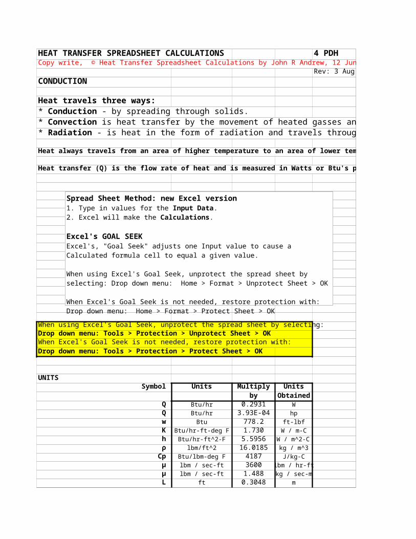
HEAT TRANSFER SPREADSHEET CALCULATIONS 4 PDH Rev: 3 Aug CONDUCTION Heat travels three ways: Heat always travels from an area of higher temperature to an area of lower tem Heat transfer (Q) is the flow rate of heat and is measured in Watts or Btu's p When using Excel's Goal Seek, unprotect the spread sheet by selecting: Drop down menu: Tools > Protection > Unprotect Sheet > OK When Excel's Goal Seek is not needed, restore protection with: Drop down menu: Tools > Protection > Protect Sheet > OK UNITS Symbol Units Multiply Units by Obtained Q Btu/hr 0.2931 W Q Btu/hr 3.93E-04 hp w Btu 778.2 ft-lbf K Btu/hr-ft-deg F 1.730 W / m-C h Btu/hr-ft^2-F 5.5956 W / m^2-C ρ lbm/ft^2 16.0185 kg / m^3 Cp Btu/lbm-deg F 4187 J/kg-C μ lbm / sec-ft 3600 lbm / hr-ft μ lbm / sec-ft 1.488 kg / sec-m L ft 0.3048 m Copy write, © Heat Transfer Spreadsheet Calculations by John R Andrew, 12 Jun * Conduction - by spreading through solids. * Convection is heat transfer by the movement of heated gasses an * Radiation - is heat in the form of radiation and travels throug Spread Sheet Method: new Excel version 1. Type in values for the Input Data. 2. Excel will make the Calculations. Excel's GOAL SEEK Excel's, "Goal Seek" adjusts one Input value to cause a Calculated formula cell to equal a given value. When using Excel's Goal Seek, unprotect the spread sheet by selecting: Drop down menu: Home > Format > Unprotect Sheet > OK When Excel's Goal Seek is not needed, restore protection with: Drop down menu: Home > Format > Protect Sheet > OK
Transcript of · XLS file · Web view · 2014-08-062D HEAT TRANSFER EXCEL'S SOLVER >...
HEAT TRANSFER SPREADSHEET CALCULATIONS 4 PDH
Rev: 3 Aug 2014CONDUCTION
Heat travels three ways:
Heat always travels from an area of higher temperature to an area of lower temperature.
Heat transfer (Q) is the flow rate of heat and is measured in Watts or Btu's per hour.
When using Excel's Goal Seek, unprotect the spread sheet by selecting:Drop down menu: Tools > Protection > Unprotect Sheet > OK When Excel's Goal Seek is not needed, restore protection with:Drop down menu: Tools > Protection > Protect Sheet > OK
UNITSSymbol Units Multiply Units
by ObtainedQ Btu/hr 0.2931 WQ Btu/hr 3.93E-04 hpw Btu 778.2 ft-lbfK Btu/hr-ft-deg F 1.730 W / m-Ch Btu/hr-ft^2-F 5.5956 W / m^2-Cρ lbm/ft^2 16.0185 kg / m^3
Cp Btu/lbm-deg F 4187 J/kg-Cμ lbm / sec-ft 3600 lbm / hr-ft
μ lbm / sec-ft 1.488 kg / sec-mL ft 0.3048 m
Copy write, © Heat Transfer Spreadsheet Calculations by John R Andrew, 12 June 2011
* Conduction - by spreading through solids.* Convection is heat transfer by the movement of heated gasses and liquids.* Radiation - is heat in the form of radiation and travels through space at the speed of light.
Spread Sheet Method: new Excel version1. Type in values for the Input Data.2. Excel will make the Calculations.
Excel's GOAL SEEK Excel's, "Goal Seek" adjusts one Input value to cause a Calculated formula cell to equal a given value.
When using Excel's Goal Seek, unprotect the spread sheet by selecting: Drop down menu: Home > Format > Unprotect Sheet > OK
When Excel's Goal Seek is not needed, restore protection with:Drop down menu: Home > Format > Protect Sheet > OK
L in 25.4 mmL in 0.0254 mF lbf 4.4482 Nw ft-lbf 1.3558 N-m ν ft^2 / sec 0.0929 m^2 / s
Heat transfer is measured in feet and meter units.
Use the above units table from left to right:Input Data
Units = 42Multiply by = 0.0254
CalculationsUnits Obtained = 1.067
Use the above units table from right to left:Input Data
Units Obtained = 22Divide by = 5.5956
CalculationsUnits = 3.932
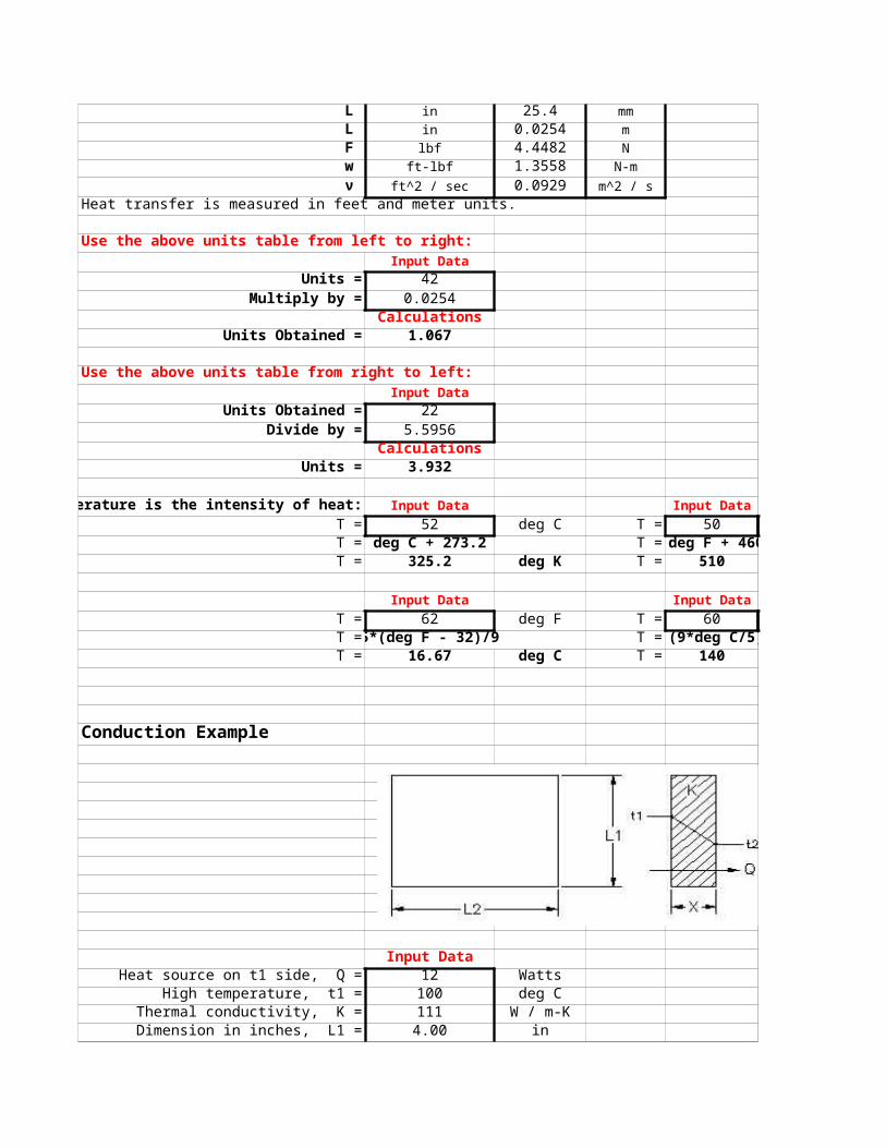
Temperature is the intensity of heat: Input Data Input DataT = 52 deg C T = 50 deg FT = deg C + 273.2 T = deg F + 460T = 325.2 deg K T = 510 deg R
Input Data Input DataT = 62 deg F T = 60 deg CT = 5*(deg F - 32)/9 T = (9*deg C/5) + 32T = 16.67 deg C T = 140 deg F
Conduction Example
Input DataHeat source on t1 side, Q = 12 Watts
High temperature, t1 = 100 deg CThermal conductivity, K = 111 W / m-KDimension in inches, L1 = 4.00 in
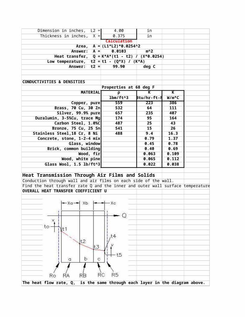
Dimension in inches, L2 = 4.00 inThickness in inches, X = 0.375 in
CalculationArea, A = (L1*L2)*0.0254^2
Answer: A = 0.0103 m^2Heat transfer, Q = K*A*(t1 - t2) / (X*0.0254)
Low temperature, t2 = t1 - (Q*X) / (K*A)Answer: t2 = 99.90 deg C
CONDUCTIVITIES & DENSITIESProperties at 68 deg F
MATERIAL ρ K Klbm/ft^3 Btu/hr-ft-F W/m*C
Copper, pure 559 223 386Brass, 70 Cu, 30 Zn 532 64 111
Silver, 99.9% pure 657 235 407Duralumin, 3-5%Cu, trace Mg 174 95 164
Carbon Steel, 1.0%C 487 25 43Bronze, 75 Cu, 25 Sn 541 15 26
Stainless Steel,18 Cr, 8 Ni 488 9.4 16.3Concrete, stone, 1-2-4 mix 0.79 1.37
Glass, window 0.45 0.78Brick, common building 0.40 0.69
Wood, fir 0.063 0.109Wood, white pine 0.065 0.112
Glass Wool, 1.5 lb/ft^3 0.022 0.038
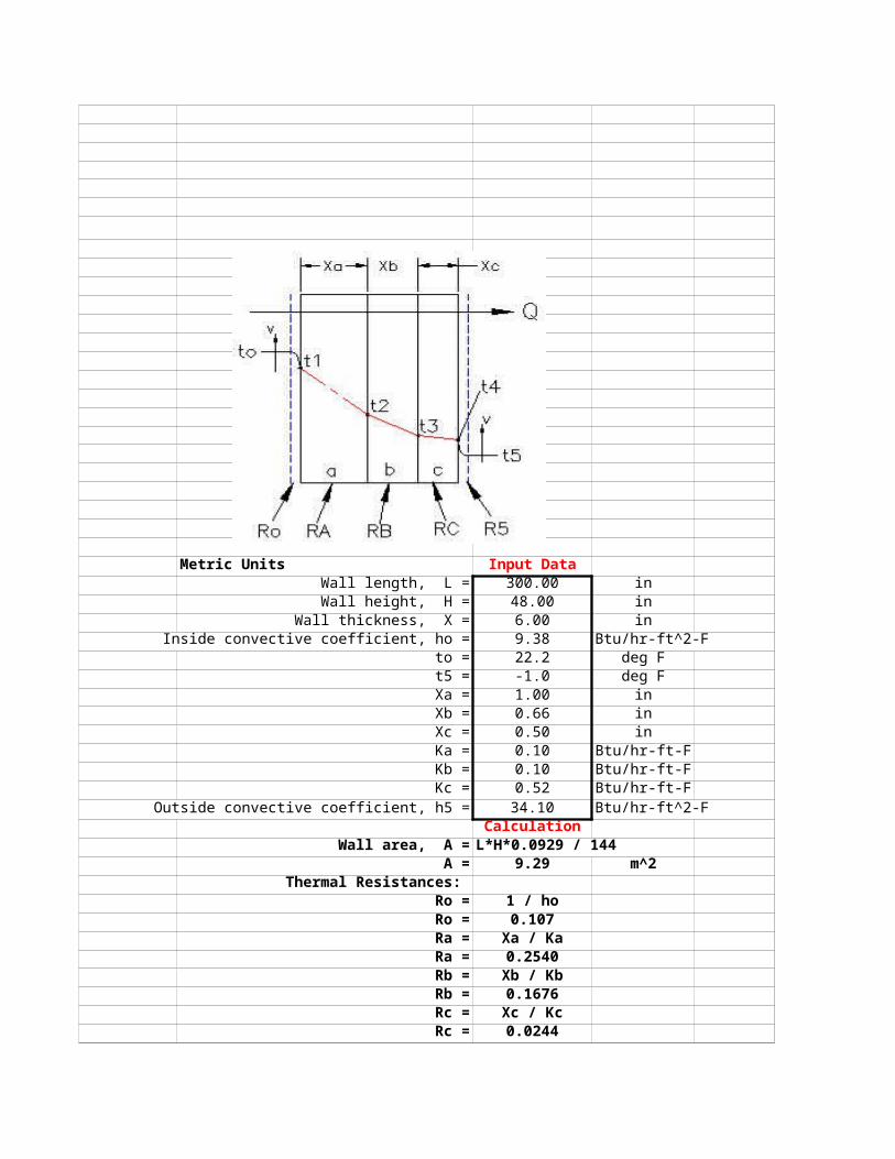
Heat Transmission Through Air Films and SolidsConduction through wall and air films on each side of the wall.Find the heat transfer rate Q and the inner and outer wall surface temperatures.OVERALL HEAT TRANSFER COEFFICIENT U
The heat flow rate, Q, is the same through each layer in the diagram above.
Thermal Resistances of LayersHeat transfer per unit area, Q / A = (t1 - t2) / (Xa / Ka) Equation 1
Heat intensity = t1 -t2
Thermal resistance for layer a, Ra = Xa / Ka
Thermal resistance for layer o, Ro = 1/ ho
Overall heat transfer rate, Q / A = (t1 -t4) / (Ra + Rb + Rc)
Overall temperature difference, ∆T= t1 - t4
Overall heat transfer coefficient, U = 1 / (A * Σ Rn)
Heat transfer per unit area, Q / A = U*(∆T)
U.S. Units Input DataWall length, L = 300.00 inWall height, H = 48.00 in
Wall thickness, X = 7.00 inInside convective coefficient, ho = 2 Btu/hr-ft^2-F
to = 70.0 deg Ft5 = 36.0 deg F
Thickness, Xa = 1.00 inXb = 4.00 inXc = 0.75 in
Thermal conductivity, Ka = 0.065 Btu/hr-ft-FThermal conductivity, Kb = 0.400 Btu/hr-ft-FThermal conductivity, Kc = 0.280 Btu/hr-ft-F
Outside convective coefficient, h5 = 5.80 Btu/hr-ft^2-FCalculation
Wall area, A = L*H / 144A = 100.00 ft^2
Thermal ResistancesRo = 1 / hoRo = 0.500Ra = Xa / Ka
Ra = 1.2821 Rb = Xb / Kb
Rb = 0.8333Rc = Xc / Kc
Rc = 0.2232
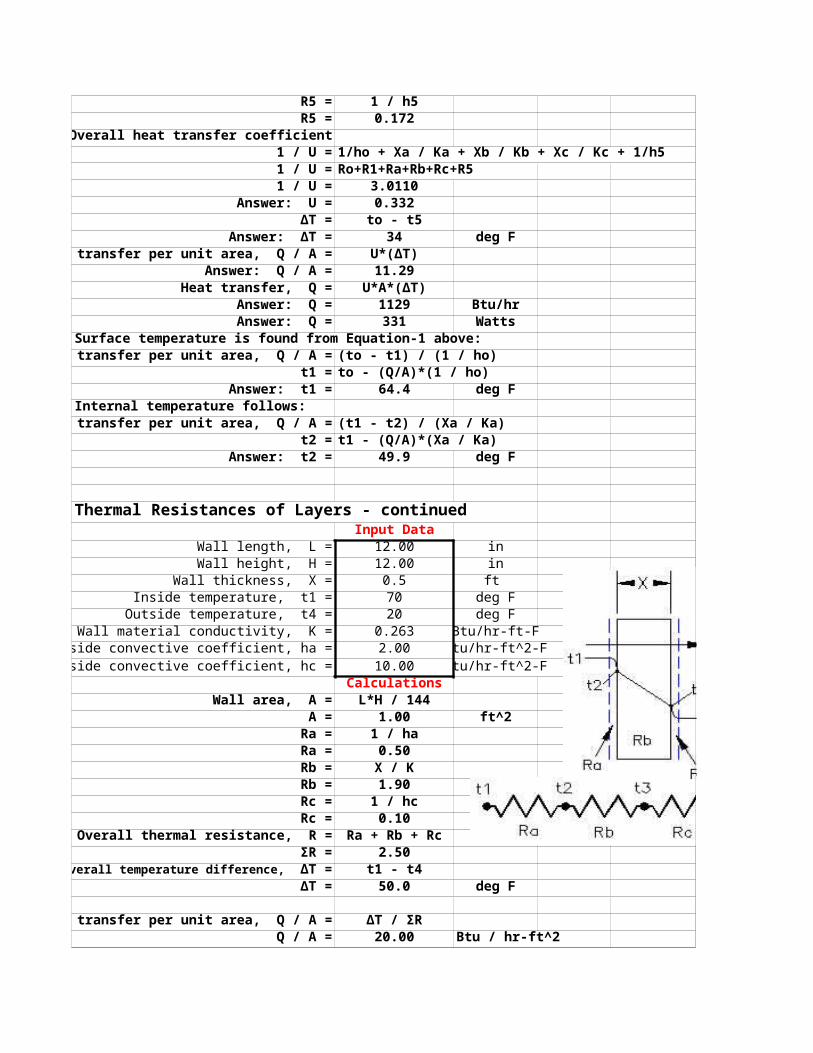
R5 = 1 / h5R5 = 0.172
Overall heat transfer coefficient1 / U = 1/ho + Xa / Ka + Xb / Kb + Xc / Kc + 1/h51 / U = Ro+R1+Ra+Rb+Rc+R51 / U = 3.0110
Answer: U = 0.332∆T = to - t5
Answer: ∆T = 34 deg FHeat transfer per unit area, Q / A = U*(∆T)
Answer: Q / A = 11.29Heat transfer, Q = U*A*(∆T)
Answer: Q = 1129 Btu/hrAnswer: Q = 331 Watts
Surface temperature is found from Equation-1 above:Heat transfer per unit area, Q / A = (to - t1) / (1 / ho)
t1 = to - (Q/A)*(1 / ho)Answer: t1 = 64.4 deg F
Internal temperature follows:Heat transfer per unit area, Q / A = (t1 - t2) / (Xa / Ka)
t2 = t1 - (Q/A)*(Xa / Ka)Answer: t2 = 49.9 deg F
Thermal Resistances of Layers - continuedInput Data
Wall length, L = 12.00 inWall height, H = 12.00 in
Wall thickness, X = 0.5 ft Inside temperature, t1 = 70 deg F
Outside temperature, t4 = 20 deg FWall material conductivity, K = 0.263 Btu/hr-ft-F
Inside convective coefficient, ha = 2.00 Btu/hr-ft^2-FOutside convective coefficient, hc = 10.00 Btu/hr-ft^2-F
CalculationsWall area, A = L*H / 144
A = 1.00 ft^2Ra = 1 / ha Ra = 0.50Rb = X / KRb = 1.90Rc = 1 / hc Rc = 0.10
Overall thermal resistance, R = Ra + Rb + RcΣR = 2.50
t1 - t4∆T = 50.0 deg F
Heat transfer per unit area, Q / A = ∆T / ΣRQ / A = 20.00 Btu / hr-ft^2
Overall temperature difference, ∆T =
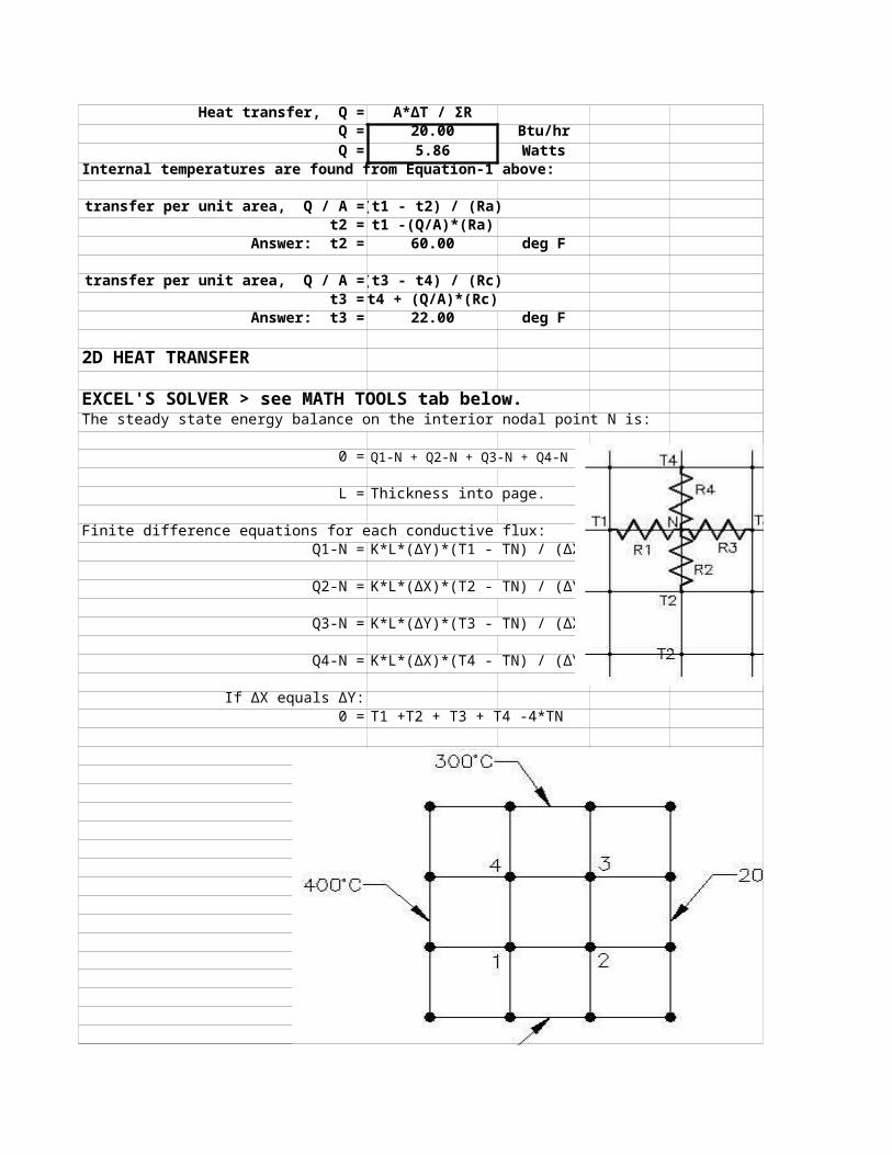
Heat transfer, Q = A*∆T / ΣRQ = 20.00 Btu/hr Q = 5.86 Watts
Internal temperatures are found from Equation-1 above:
Heat transfer per unit area, Q / A = (t1 - t2) / (Ra)t2 = t1 -(Q/A)*(Ra)
Answer: t2 = 60.00 deg F
Heat transfer per unit area, Q / A = (t3 - t4) / (Rc)t3 = t4 + (Q/A)*(Rc)
Answer: t3 = 22.00 deg F
2D HEAT TRANSFER
EXCEL'S SOLVER > see MATH TOOLS tab below.The steady state energy balance on the interior nodal point N is:
0 = Q1-N + Q2-N + Q3-N + Q4-N
L = Thickness into page.
Finite difference equations for each conductive flux:Q1-N = K*L*(∆Y)*(T1 - TN) / (∆X)
Q2-N = K*L*(∆X)*(T2 - TN) / (∆Y)
Q3-N = K*L*(∆Y)*(T3 - TN) / (∆X)
Q4-N = K*L*(∆X)*(T4 - TN) / (∆Y)
If ∆X equals ∆Y:0 = T1 +T2 + T3 + T4 -4*TN
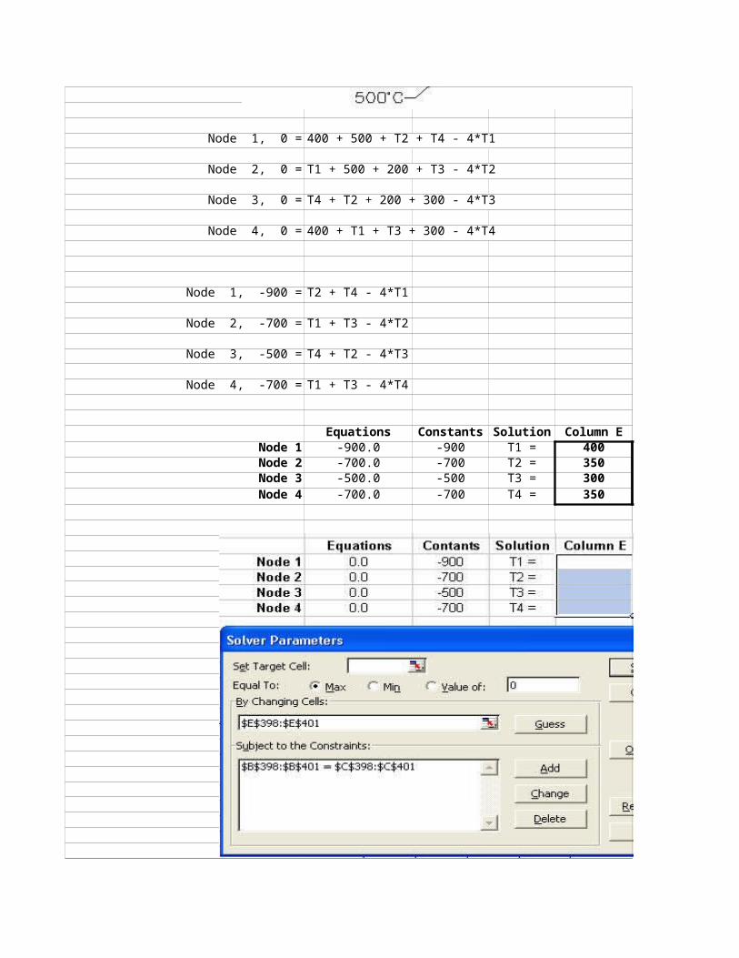
Node 1, 0 = 400 + 500 + T2 + T4 - 4*T1
Node 2, 0 = T1 + 500 + 200 + T3 - 4*T2
Node 3, 0 = T4 + T2 + 200 + 300 - 4*T3
Node 4, 0 = 400 + T1 + T3 + 300 - 4*T4
Node 1, -900 = T2 + T4 - 4*T1
Node 2, -700 = T1 + T3 - 4*T2
Node 3, -500 = T4 + T2 - 4*T3
Node 4, -700 = T1 + T3 - 4*T4
Equations Constants Solution Column ENode 1 -900.0 -900 T1 = 400 deg CNode 2 -700.0 -700 T2 = 350 deg CNode 3 -500.0 -500 T3 = 300 deg CNode 4 -700.0 -700 T4 = 350 deg C
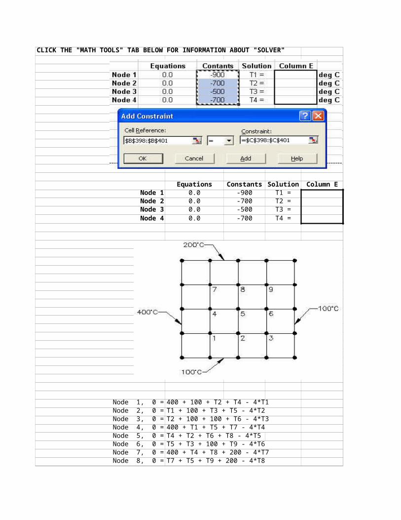
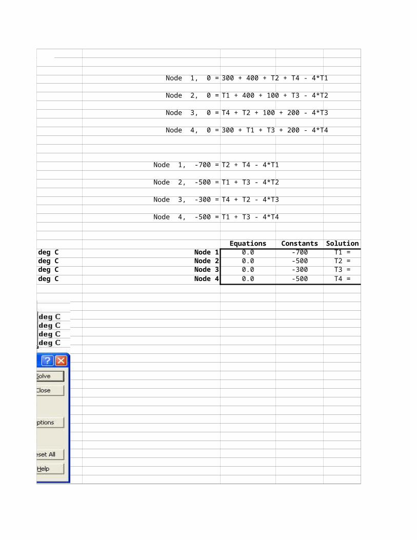
CLICK THE "MATH TOOLS" TAB BELOW FOR INFORMATION ABOUT "SOLVER"
Equations Constants Solution Column ENode 1 0.0 -900 T1 = deg CNode 2 0.0 -700 T2 = deg CNode 3 0.0 -500 T3 = deg CNode 4 0.0 -700 T4 = deg C
Node 1, 0 = 400 + 100 + T2 + T4 - 4*T1Node 2, 0 = T1 + 100 + T3 + T5 - 4*T2Node 3, 0 = T2 + 100 + 100 + T6 - 4*T3Node 4, 0 = 400 + T1 + T5 + T7 - 4*T4Node 5, 0 = T4 + T2 + T6 + T8 - 4*T5Node 6, 0 = T5 + T3 + 100 + T9 - 4*T6Node 7, 0 = 400 + T4 + T8 + 200 - 4*T7Node 8, 0 = T7 + T5 + T9 + 200 - 4*T8
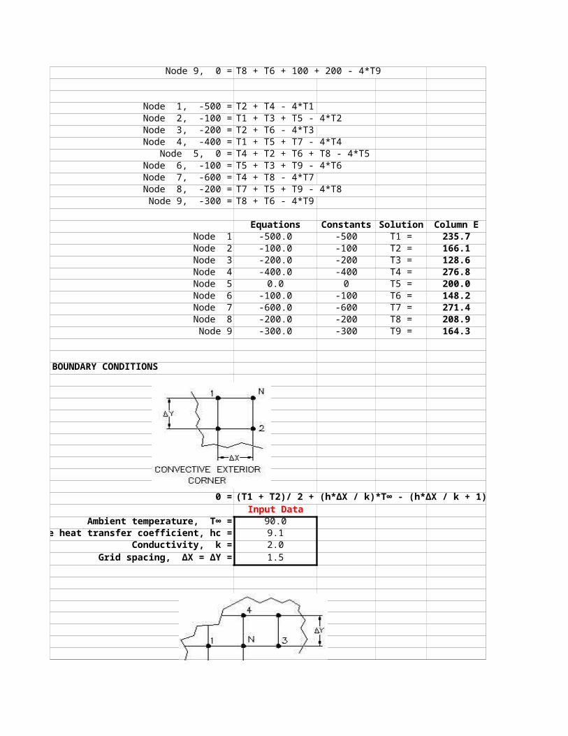
Node 9, 0 = T8 + T6 + 100 + 200 - 4*T9
Node 1, -500 = T2 + T4 - 4*T1Node 2, -100 = T1 + T3 + T5 - 4*T2Node 3, -200 = T2 + T6 - 4*T3Node 4, -400 = T1 + T5 + T7 - 4*T4
Node 5, 0 = T4 + T2 + T6 + T8 - 4*T5Node 6, -100 = T5 + T3 + T9 - 4*T6Node 7, -600 = T4 + T8 - 4*T7Node 8, -200 = T7 + T5 + T9 - 4*T8Node 9, -300 = T8 + T6 - 4*T9
Equations Constants Solution Column ENode 1 -500.0 -500 T1 = 235.7 deg CNode 2 -100.0 -100 T2 = 166.1 deg CNode 3 -200.0 -200 T3 = 128.6 deg CNode 4 -400.0 -400 T4 = 276.8 deg CNode 5 0.0 0 T5 = 200.0 deg CNode 6 -100.0 -100 T6 = 148.2 deg CNode 7 -600.0 -600 T7 = 271.4 deg CNode 8 -200.0 -200 T8 = 208.9 deg CNode 9 -300.0 -300 T9 = 164.3 deg C
BOUNDARY CONDITIONS
0 = (T1 + T2)/ 2 + (h*∆X / k)*T∞ - (h*∆X / k + 1)*TnInput Data
Ambient temperature, T∞ = 90.0vective heat transfer coefficient, hc = 9.1
Conductivity, k = 2.0Grid spacing, ∆X = ∆Y = 1.5
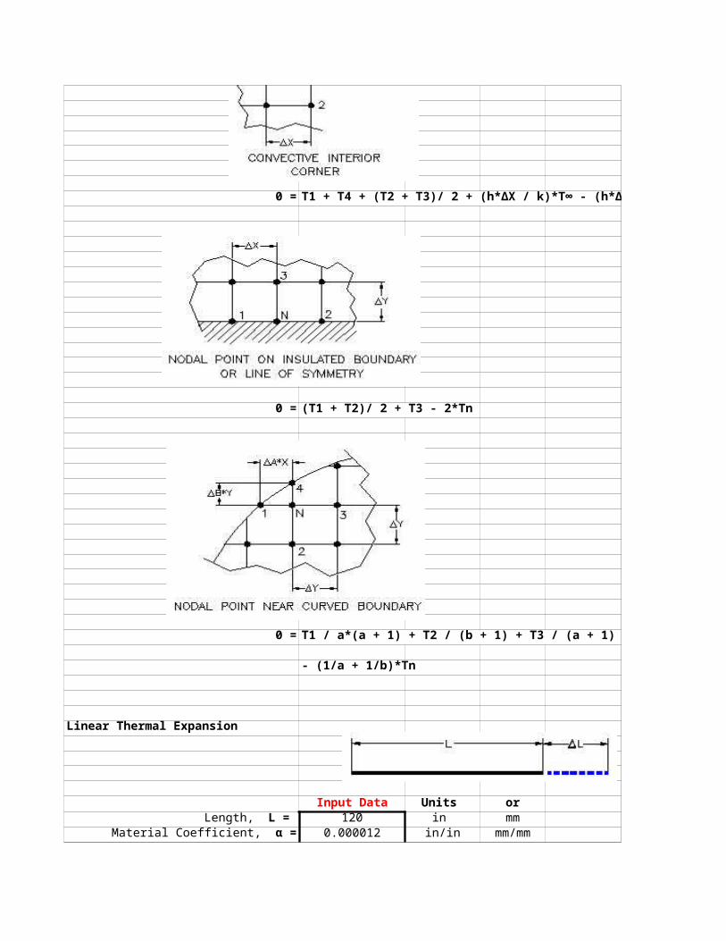
0 = T1 + T4 + (T2 + T3)/ 2 + (h*∆X / k)*T∞ - (h*∆X / k + 3)*Tn
0 = (T1 + T2)/ 2 + T3 - 2*Tn
0 = T1 / a*(a + 1) + T2 / (b + 1) + T3 / (a + 1) + T4 / b*(b + 1)
- (1/a + 1/b)*Tn
Linear Thermal Expansion
Input Data Units or
120 in mm0.000012 in/in mm/mm
Length, L = Material Coefficient, α =
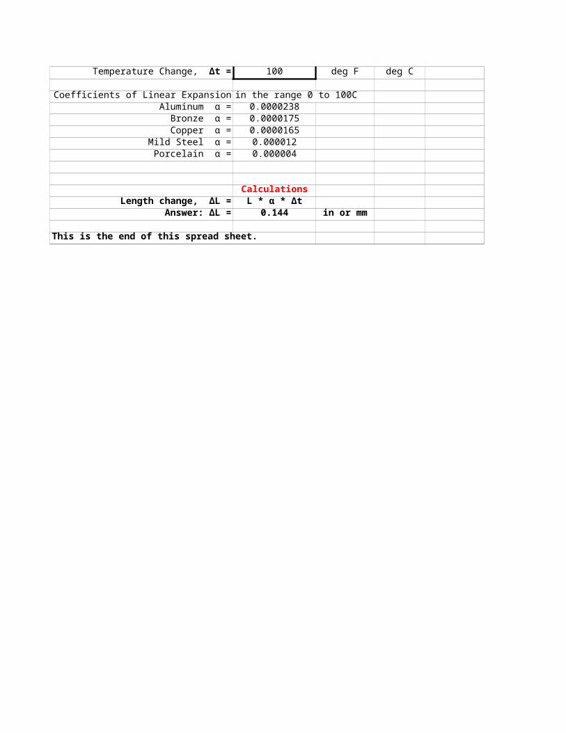
100 deg F deg C
Coefficients of Linear Expansion in the range 0 to 100C Aluminum α = 0.0000238
Bronze α = 0.0000175Copper α = 0.0000165
Mild Steel α = 0.000012Porcelain α = 0.000004
CalculationsLength change, ΔL = L * α * Δt
Answer: ΔL = 0.144 in or mm
This is the end of this spread sheet.
Temperature Change, Δt =
Spread Sheet Method: Excel-97 2003 - old version1. Type in values for the Input Data.2. Excel will make the Calculations.
Excel's GOAL SEEK Excel's, "Goal Seek" adjusts one Input value to cause a Calculated formula cell to equal a given value.
When using Excel's Goal Seek, unprotect the spread sheet by selecting: Drop down menu: Tools > Protection > Unprotect Sheet > OK
When Excel's Goal Seek is not needed, restore protection with:Drop down menu: Tools > Protection > Protect Sheet > OK


Metric Units Input DataWall length, L = 300.00 inWall height, H = 48.00 in
Wall thickness, X = 6.00 inInside convective coefficient, ho = 9.38 Btu/hr-ft^2-F
to = 22.2 deg Ft5 = -1.0 deg F
Xa = 1.00 inXb = 0.66 inXc = 0.50 inKa = 0.10 Btu/hr-ft-FKb = 0.10 Btu/hr-ft-FKc = 0.52 Btu/hr-ft-F
Outside convective coefficient, h5 = 34.10 Btu/hr-ft^2-FCalculation
Wall area, A = L*H*0.0929 / 144A = 9.29 m^2
Thermal Resistances: Ro = 1 / hoRo = 0.107Ra = Xa / Ka
Ra = 0.2540 Rb = Xb / Kb
Rb = 0.1676Rc = Xc / Kc
Rc = 0.0244
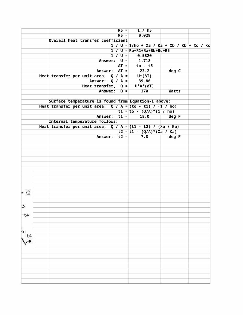
R5 = 1 / h5R5 = 0.029
Overall heat transfer coefficient1 / U = 1/ho + Xa / Ka + Xb / Kb + Xc / Kc + 1/h51 / U = Ro+R1+Ra+Rb+Rc+R51 / U = 0.5820
Answer: U = 1.718∆T = to - t5
Answer: ∆T = 23.2 deg CHeat transfer per unit area, Q / A = U*(∆T)
Answer: Q / A = 39.86Heat transfer, Q = U*A*(∆T)
Answer: Q = 370 Watts
Surface temperature is found from Equation-1 above:Heat transfer per unit area, Q / A = (to - t1) / (1 / ho)
t1 = to - (Q/A)*(1 / ho)Answer: t1 = 18.0 deg F
Internal temperature follows:Heat transfer per unit area, Q / A = (t1 - t2) / (Xa / Ka)
t2 = t1 - (Q/A)*(Xa / Ka)Answer: t2 = 7.8 deg F
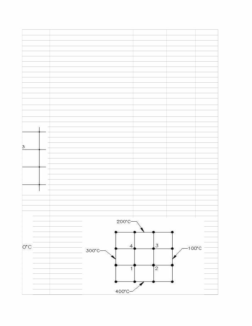
Node 1, 0 = 300 + 400 + T2 + T4 - 4*T1
Node 2, 0 = T1 + 400 + 100 + T3 - 4*T2
Node 3, 0 = T4 + T2 + 100 + 200 - 4*T3
Node 4, 0 = 300 + T1 + T3 + 200 - 4*T4
Node 1, -700 = T2 + T4 - 4*T1
Node 2, -500 = T1 + T3 - 4*T2
Node 3, -300 = T4 + T2 - 4*T3
Node 4, -500 = T1 + T3 - 4*T4
Equations Constants Solution Column ENode 1 0.0 -700 T1 = deg CNode 2 0.0 -500 T2 = deg CNode 3 0.0 -300 T3 = deg CNode 4 0.0 -500 T4 = deg C

HEAT TRANSFER SPREADSHEET CALCULATIONS 4 PDH
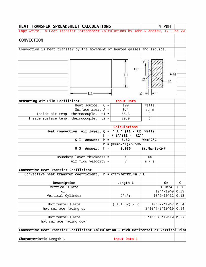
CONVECTION
Convection is heat transfer by the movement of heated gasses and liquids.
Measuring Air Film Coefficient Input DataHeat source, Q = 100 Watts Surface area, A = 0.4 sq m
Inside air temp. thermocouple, t1 = 65.3 CInside surface temp. thermocouple, t2 = 20.0 C
CalculationsHeat convection, air layer, Q = h * A * (t1 - t2) Watts
h = Q / (A*(t1 - t2))S.I. Answer: h = 5.52 W/m^2*C
h = (W/m^2*K)/5.596 U.S. Answer: h = 0.986 Btu/hr-ft^2*F
Boundary layer thickness = X mmAir flow velocity = V m / s
Convective Heat Transfer CoefficientConvective heat transfer coefficient, h = k*C*(Gr*Pr)^n / L
Description Length L Gr C nVertical Plate < 10^4 1.36 0.200
or 10^4<10^9 0.59 0.250Vertical Cylinder 2*π*r 10^9<10^12 0.13 0.333
Horizontal Plate (S1 + S2) / 2 10^5<2*10^7 0.54 0.250hot surface facing up 2*10^7<3*10^10 0.14 0.333
Horizontal Plate 3*10^5<3*10^10 0.27 0.250hot surface facing down
Convective Heat Transfer Coefficient Calculation - Pick Horizontal or Vertical Plate:
Characteristic Length L Input Data-1
Copy write, © Heat Transfer Spreadsheet Calculations by John R Andrew, 12 June 2011

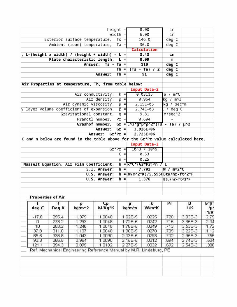
height = 8.00 inwidth = 6.00 in
Exterior surface temperature, Ts = 146.0 deg CAmbient (room) temperature, Ta = 36.0 deg C
Calculation P1Length, L=(height x width) / (height + width) = L = 3.43 in
Plate characteristic length, L = 0.09 mAnswer: Ts - Ta = 110 deg C
Th = (Ts + Ta) / 2 deg CAnswer: Th = 91 deg C
Air Properties at temperature, Th, from table below:Input Data-2
Air conductivity, k = 0.03115 W / m*C Air density, ρ = 0.964 kg / m^3
Air dynamic viscosity, μ = 2.15E-05 kg / sec*mBoundary layer volume coefficient of expansion, β = 2.74E-03 1 / deg C
Gravitational constant, g = 9.81 m/sec^2Prandtl number, Pr = 0.694 -
Grashof number, Gr = L^3*g*β*ρ^2*(Ts - Ta) / μ^2Answer: Gr = 3.926E+06
Answer: Gr*Pr = 2.725E+06C and n below are found in the table above for the Gr*Pr value calculated here.
Input Data-3Gr*Pr = 10^3 < 10^9
C = 0.53n = 0.25
Nusselt Equation, Air Film Coefficient, h = k*C*(Gr*Pr)^n / LS.I. Answer: h = 7.702 W / m^2*C
U.S. Answer: h = (W/m^2*K)/5.5956 Btu/hr-ft^2*FU.S. Answer: h = 1.376 Btu/hr-ft^2*F

P2
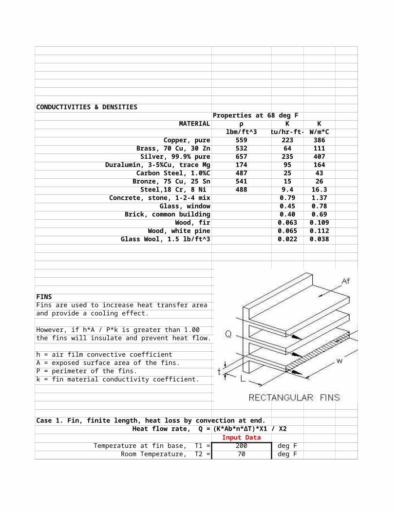
CONDUCTIVITIES & DENSITIESProperties at 68 deg F
MATERIAL ρ K Klbm/ft^3 Btu/hr-ft-F W/m*C
Copper, pure 559 223 386Brass, 70 Cu, 30 Zn 532 64 111
Silver, 99.9% pure 657 235 407Duralumin, 3-5%Cu, trace Mg 174 95 164
Carbon Steel, 1.0%C 487 25 43Bronze, 75 Cu, 25 Sn 541 15 26
Steel,18 Cr, 8 Ni 488 9.4 16.3Concrete, stone, 1-2-4 mix 0.79 1.37
Glass, window 0.45 0.78Brick, common building 0.40 0.69
Wood, fir 0.063 0.109Wood, white pine 0.065 0.112
Glass Wool, 1.5 lb/ft^3 0.022 0.038
FINSFins are used to increase heat transfer areaand provide a cooling effect.
However, if h*A / P*k is greater than 1.00the fins will insulate and prevent heat flow.
h = air film convective coefficientA = exposed surface area of the fins.P = perimeter of the fins.k = fin material conductivity coefficient.
Case 1. Fin, finite length, heat loss by convection at end.Heat flow rate, Q = (K*Ab*n*ΔT)*X1 / X2
Input DataTemperature at fin base, T1 = 200 deg F
Room Temperature, T2 = 70 deg F

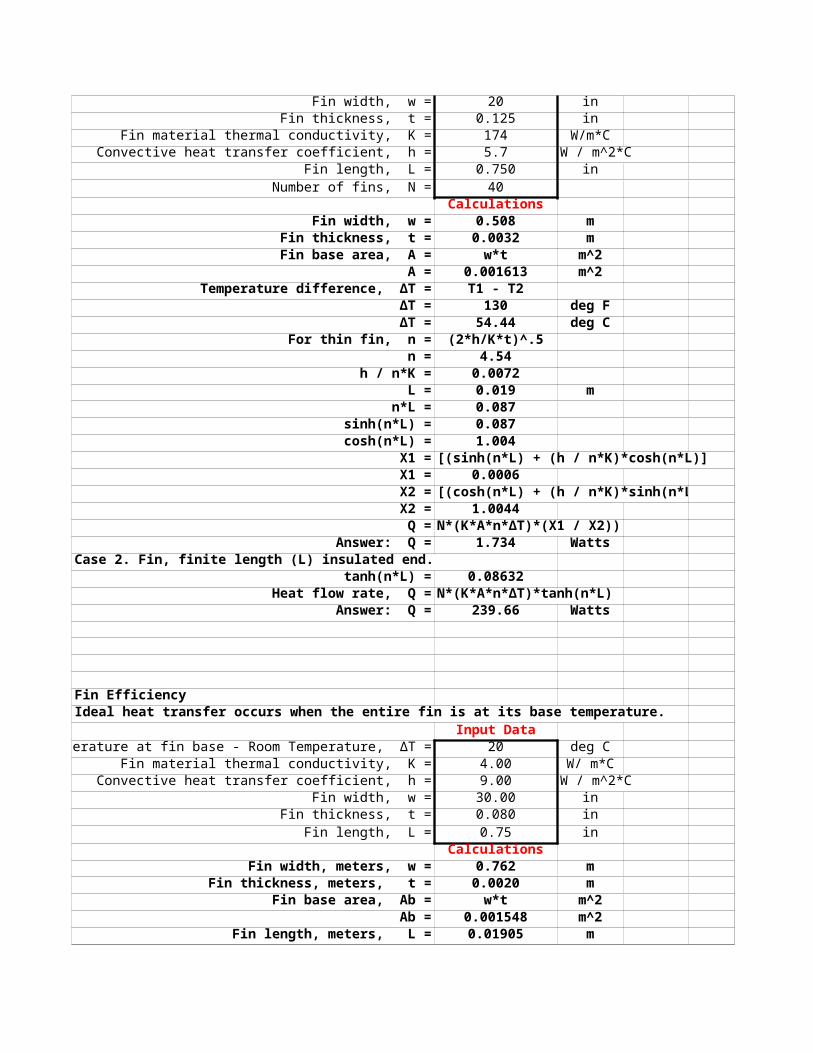
Fin width, w = 20 inFin thickness, t = 0.125 in
Fin material thermal conductivity, K = 174 W/m*CConvective heat transfer coefficient, h = 5.7 W / m^2*C
Fin length, L = 0.750 inNumber of fins, N = 40
Calculations P3Fin width, w = 0.508 m
Fin thickness, t = 0.0032 mFin base area, A = w*t m^2
A = 0.001613 m^2Temperature difference, ΔT = T1 - T2
ΔT = 130 deg F ΔT = 54.44 deg C
For thin fin, n = (2*h/K*t)^.5 n = 4.54
h / n*K = 0.0072L = 0.019 m
n*L = 0.087sinh(n*L) = 0.087
cosh(n*L) = 1.004X1 = [(sinh(n*L) + (h / n*K)*cosh(n*L)]X1 = 0.0006X2 = [(cosh(n*L) + (h / n*K)*sinh(n*L)]
X2 = 1.0044Q = N*(K*A*n*ΔT)*(X1 / X2))
Answer: Q = 1.734 WattsCase 2. Fin, finite length (L) insulated end.
tanh(n*L) = 0.08632Heat flow rate, Q = N*(K*A*n*ΔT)*tanh(n*L)
Answer: Q = 239.66 Watts
Fin EfficiencyIdeal heat transfer occurs when the entire fin is at its base temperature.
Input DataTemperature at fin base - Room Temperature, ΔT = 20 deg C
Fin material thermal conductivity, K = 4.00 W/ m*CConvective heat transfer coefficient, h = 9.00 W / m^2*C
Fin width, w = 30.00 inFin thickness, t = 0.080 in
Fin length, L = 0.75 inCalculations
Fin width, meters, w = 0.762 mFin thickness, meters, t = 0.0020 m
Fin base area, Ab = w*t m^2Ab = 0.001548 m^2
Fin length, meters, L = 0.01905 m

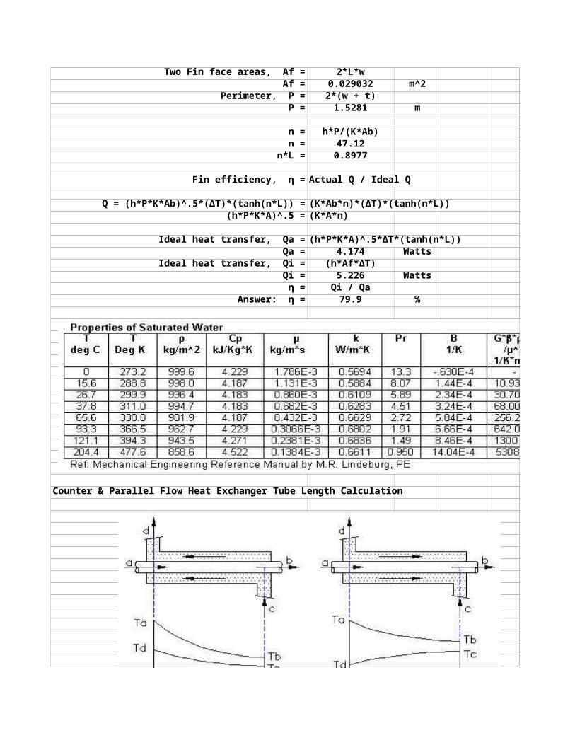
Two Fin face areas, Af = 2*L*w Af = 0.029032 m^2
Perimeter, P = 2*(w + t) P = 1.5281 m
n = h*P/(K*Ab)n = 47.12
n*L = 0.8977 P4
Fin efficiency, η = Actual Q / Ideal Q
Q = (h*P*K*Ab)^.5*(ΔT)*(tanh(n*L)) = (K*Ab*n)*(ΔT)*(tanh(n*L)) (h*P*K*A)^.5 = (K*A*n)
Ideal heat transfer, Qa = (h*P*K*A)^.5*ΔT*(tanh(n*L))Qa = 4.174 Watts
Ideal heat transfer, Qi = (h*Af*ΔT) Qi = 5.226 Watts
η = Qi / QaAnswer: η = 79.9 %
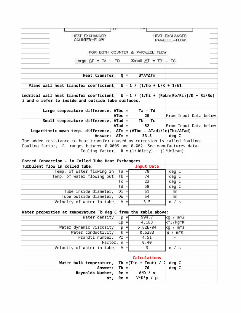
Counter & Parallel Flow Heat Exchanger Tube Length Calculation

P5Heat transfer, Q = U*A*∆Tm
Plane wall heat transfer coefficient, U = 1 / (1/ho + L/K + 1/h1
Cylindrical wall heat transfer coefficient, U = 1 / (1/hi + [RoLn(Ro/Ri)]/K + Ri/Ro)i and o refer to inside and outside tube surfaces.
Large temperature difference, ΔTbc = Ta - TdΔTbc = 20 From Input Data below.
Small temperature difference, ΔTad = Tb - TcΔTad = 52 From Input Data below.
Logarithmic mean temp. difference, ΔTm = (ΔTbc - ΔTad)/ln(Tbc/ΔTad)Answer: ΔTm = 33.5 deg C
The added resistance to heat transfer caused by corrosion is called fouling.Fouling factor, R ranges between 0.0005 and 0.002. See manufactures data.
Fouling factor, R = (1/Udirty) - (1/Uclean)
Forced Convection - in Coiled Tube Heat ExchangersTurbulent flow in coiled tube. Input Data
Temp. of water flowing in, Ta = 78 deg CTemp. of water flowing out, Tb = 74 deg C
Tc = 22 deg CTd = 58 deg C
Tube inside diameter, Di = 51 mmTube outside diameter, Do = 54 mmVelocity of water in tube, V = 3.5 m / s
Water properties at temperature Tb deg C from the table above: Water density, ρ = 994.7 kg / m^2
Cp = 4.183 k*J/kg*KWater dynamic viscosity, μ = 6.82E-04 kg / m*s
Water conductivity, k = 0.6283 W / m*KPrandtl number, Pr = 4.51 -
Factor, n = 0.40Velocity of water in tube, V = 3 m / s
CalculationsWater bulk temperature, Tb = (Tin + Tout) / 2 deg C
Answer: Tb = 76 deg CReynolds Number, Re = V*D / ν
or, Re = V*D*ρ / μ
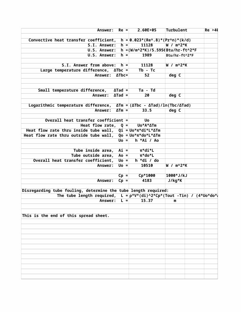
Answer: Re = 2.60E+05 Turbulent Re >4000
Convective heat transfer coefficient, h = 0.023*(Re^.8)*(Pr^n)*(k/d)S.I. Answer: h = 11128 W / m^2*K
U.S. Answer: h = (W/m^2*K)/5.5956 Btu/hr-ft^2*FU.S. Answer: h = 1989 Btu/hr-ft^2*F
S.I. Answer from above: h = 11128 W / m^2*KLarge temperature difference, ΔTbc = Tb - Tc
Answer: ΔTbc= 52 deg C P6
Small temperature difference, ΔTad = Ta - Td
Answer: ΔTad = 20 deg C
Logarithmic temperature difference, ΔTm = (ΔTbc - ΔTad)/ln(Tbc/ΔTad)Answer: ΔTm = 33.5 deg C
Overall heat transfer coefficient = UoHeat flow rate, Q = Uo*A*ΔTm
Heat flow rate thru inside tube wall, Qi = Uo*π*di*L*ΔTmHeat flow rate thru outside tube wall, Qo = Uo*π*do*L*ΔTm
Uo = h *Ai / Ao
Tube inside area, Ai = π*di*LTube outside area, Ao = π*do*L
Overall heat transfer coefficient, Uo = h *di / do Answer: Uo = 10510 W / m^2*K
Cp = Cp*1000 1000*J/kJAnswer: Cp = 4183 J/kg*K
Disregarding tube fouling, determine the tube length required: The tube length required, L = ρ*V*(di)^2*Cp*(Tout -Tin) / (4*Uo*do*ΔTm)
Answer: L = 15.37 m
This is the end of this spread sheet.
P7
HEAT TRANSFER SPREADSHEET CALCULATIONS 4 PDH
RADIATION
Radiant heat energy is proportional to the 4th power of the absolute temperature.
Heat Radiation Upon a Surfaceabsorbtivity
Fraction of heat energy reflected, ρ = reflectivityFraction of heat energy passed thru., τ = transmissivity (transparent; solids, liquids, & gasses)
1.00
Black Body RadiationAn ideal black body absorbs all incident
1.00therefore, ρ = 0 and τ = 0
Input Datat = 22 deg C
S.I. absolute temperature, Tk = t + 273.2 deg KAnswer: Tk = 295.2 deg K
Input Datat = 70 deg F
U.S. absolute temperature, Tr = t + 459.8 deg RAnswer: Tr = 529.8 deg R
Radiation Example Input DataMaterial surface emissivity, e = 0.91 -
Stefan-Boltzmann constant, σ = 5.67E-08 W / m^2-K^4Dimension, L1 = 20.00 mDimension, L2 = 3.00 m
Surface temperature, t1 = 38 deg CCalculation
Area, A = L1*L2
Copy write, © Heat Transfer Spreadsheet Calculations by John R Andrew, 12 June 2011
Heat in the form of radiation travels through space at the speed of light.
Fraction of heat energy absorbed, α =
By definition, α + ρ + τ =
radiation so that, α =
Answer: A = 60.00 m^2Absolute temperature. T = C + 273
T = 311 deg AbsRadiant thermal flux reflected, Q = e*σ*T^4
Answer: Q = 482.7 Watts P1Q is the radiant thermal flux per square foot reflected by the wall.
The total hemispherical heat radiation from a black body surface (A) is, Eb = σ*T^4 W /m^2*K^4
Stefan-Boltzmann constant, σ = 5.670E-08 W /m^2*K^4
Stefan-Boltzmann constant, σ = 1.714E-09 Btu/h*ft^2*R
Gray body radiation, Eg = ε*σ*T^4 W /m^2*K^4Gray body radiation factor = ε
Configuration or Emissivity Factor, CF = E1 / E2Radiation transmitted from surface 1 = E1 W /m^2*K^4
Radiation transmitted to surface 2 = E2 W /m^2*K^4Surface 1 is smaller than surface 2.If surface 2 completely surrounds
surface 1, Fa = 1.00
Total radiation transmitted, Et = ε*σ*CF*(T1^4-T1^4) W /m^2*K^4
Radiation ExampleHorizontal duct under a house.What is the heat loss per unit area of the duct?
Input DataDuct diameter, D = 20 cm
Duct surface temperature, tduct = 85 CDuct emissivity, ε = 0.8
Temperature under house, twalls = 20 CSurrounding air temperature, tair = 18 C
Convective film coefficient, h = 5.5 W/ m^2*K 0.96 Btu/hr*ft^2*FP2
1. Calculate heat lost by radiation: Calculations Stefan-Boltzmann constant, σ = 5.670E-08 W /m^2*K^4
Tduct = tduct + 273Answer: Tduct = 358 deg K
Twalls = twalls + 273Answer: Twalls = 293 deg K
Surface 2 completely surrounds surface 1 Arrangement or Emissivity Factor, CF = 1.00 W/m^2*K^4
Heat transferred by radiation, Er = ε*σ*CF*(T1^4 - T2^4)Answer: Er = 411 W/m^2*K^4
2. Determine heat lost by convection:Convective heat transfer, Q / A = h*(tduct - tair)
Answer: Q / A = 368.5 W / m^2
3. Add to find total heat loss:Qtotal / Area = Er + Q / AQtotal / Area = 779 W / m^2
This is the end of this spread sheet.
P3
HEAT TRANSFER SPREADSHEET CALCULATIONS 4 PDH
MATH TOOLS
Excel can be used to facilitate and document engineering calculations.
When using Excel's Goal Seek, unprotect the spread sheet by selecting:Drop down menu: Tools > Protection > Unprotect Sheet > OK When Excel's Goal Seek is not needed, restore protection with:Drop down menu: Tools > Protection > Protect Sheet > OK
GOAL SEEK - Trial and Error by Excel Spread Sheet
The objective is to find the input heat Q that will result in the temperature T4 = 25 deg. C.
Excel spread sheets will make a trial and error iteration automatically with the tool called, "Goal Seek".
EXAMPLE - LOCKEDInput Data
Q = 5.0 Watts A = 0.25 sq m T1 = 45 deg. C h1 = 9.00 W/sq m C h2 = 5.00 W/sq m C
k = 164 W / m CL = 0.25 m
Calculations R1 = 1 / h1 sq m C/W
R1 = 0.111 sq m C/W R2 = L / k m*C / W R2 = 0.0015 m*C / W
R3 = 1 / h2 sq m C/W R3 = 0.200 sq m C/W
Q / A = (T1 -T4) / (R1 + R2 + R3)T4 = T1 - ((Q / A)*(R1 + R2 + R3))
Answer: T4 = 38.7 deg. C
PROBLEM - UNLOCKEDPractice Goal Seek below: Input Data
Q = 16.0 Watts
Copy write, © Heat Transfer Spreadsheet Calculations by John R Andrew, 12 June 2011
T4 = 38.7 deg. C in the calculation below when input heat flow Q = 5.0 Watts.
1. Select the calculated answer at red cell, T4 = 38.7 below.
2. Select: Tools > Goal Seek > Pick "To value:" > 25 > By changing: > Pick green cell, Q = 16.0 > Okay.
A = 0.25 sq m T1 = 45 deg. C h1 = 9.00 W/sq m C h2 = 5.00 W/sq m C
k = 164 W / m CL = 0.25 m
Calculations R1 = 1 / h1 sq m C/W
R1 = 0.111 sq m C/W R2 = L / k m*C / W R2 = 0.0015 m*C / W
R3 = 1 / h2 sq m C/W R3 = 0.200 sq m C/W
Q / A = (T1 -T4) / (R1 + R2 + R3)T4 = T1 - ((Q / A)*(R1 + R2 + R3))
Answer: T4 = 25.0 deg. C
EXCEL'S SOLVER > see 2D CONDUCTIONTo install Solver, click the Microsoft Office Button, click Excel Options, and click Add-Ins. In the Manage box at the bottom of the window, select Excel Add-ins, and click Go. Check the Solver Add-in box in the Add-Ins dialog box, and click OK. After Solver is installed, you can run Solver by clicking Solver in the Analysis group on the Data tab.
Step-1 Clik the "Excel Button" top left > Click "Excel Options".
This is the end of this spread sheet.


![Mechanical Engineering Research Journalconvection heat transfer of Al2O3 nanoparticle enhanced N-butyl-N-methyl pyrrolidinium bis{trifluoromethyl)sulfonyl} imide ([C4mpyrr][NTf2])](https://static.fdocument.org/doc/165x107/60180d6c8ee8432e99113cbb/mechanical-engineering-research-convection-heat-transfer-of-al2o3-nanoparticle-enhanced.jpg)