WAVEPRO 7000A SERIES SCILLOSCOPES - trs … present in XMATH, XDEV, and JTA2. Digital Filter...
14
WAVEPRO ® 7000A SERIES OSCILLOSCOPES Fast, Accurate WaveShape Analysis in an Easy-to-use Oscilloscope
Transcript of WAVEPRO 7000A SERIES SCILLOSCOPES - trs … present in XMATH, XDEV, and JTA2. Digital Filter...
WAVEPRO® 7000A SERIESOSCILLOSCOPES
Fast, AccurateWaveShape Analysisin an Easy-to-useOscilloscope
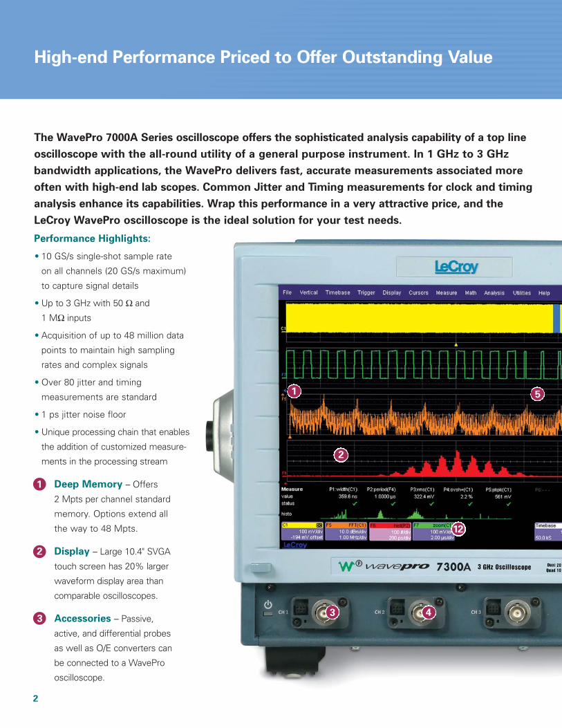
Performance Highlights:
• 10 GS/s single-shot sample rate
on all channels (20 GS/s maximum)
to capture signal details
• Up to 3 GHz with 50 Ω and
1 MΩ inputs
• Acquisition of up to 48 million data
points to maintain high sampling
rates and complex signals
• Over 80 jitter and timing
measurements are standard
• 1 ps jitter noise floor
• Unique processing chain that enables
the addition of customized measure-
ments in the processing stream
Deep Memory – Offers
2 Mpts per channel standard
memory. Options extend all
the way to 48 Mpts.
Display – Large 10.4" SVGA
touch screen has 20% larger
waveform display area than
comparable oscilloscopes.
Accessories – Passive,
active, and differential probes
as well as O/E converters can
be connected to a WavePro
oscilloscope.
2
High-end Performance Priced to Offer Outstanding Value
43
2
51
1
2
3
The WavePro 7000A Series oscilloscope offers the sophisticated analysis capability of a top line
oscilloscope with the all-round utility of a general purpose instrument. In 1 GHz to 3 GHz
bandwidth applications, the WavePro delivers fast, accurate measurements associated more
often with high-end lab scopes. Common Jitter and Timing measurements for clock and timing
analysis enhance its capabilities. Wrap this performance in a very attractive price, and the
LeCroy WavePro oscilloscope is the ideal solution for your test needs.
12
3
8
7
10
6
9
4 5 6
7
8
9
10
11
12
11
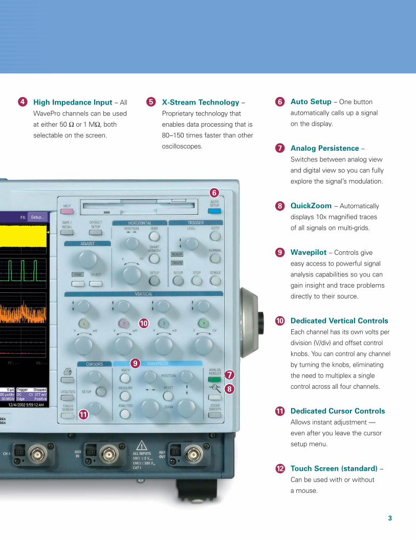
High Impedance Input – All
WavePro channels can be used
at either 50 Ω or 1 MΩ, both
selectable on the screen.
X-Stream Technology –
Proprietary technology that
enables data processing that is
80–150 times faster than other
oscilloscopes.
Auto Setup – One button
automatically calls up a signal
on the display.
Analog Persistence –
Switches between analog view
and digital view so you can fully
explore the signal’s modulation.
QuickZoom – Automatically
displays 10x magnified traces
of all signals on multi-grids.
Wavepilot – Controls give
easy access to powerful signal
analysis capabilities so you can
gain insight and trace problems
directly to their source.
Dedicated Vertical Controls
Each channel has its own volts per
division (V/div) and offset control
knobs. You can control any channel
by turning the knobs, eliminating
the need to multiplex a single
control across all four channels.
Dedicated Cursor Controls
Allows instant adjustment —
even after you leave the cursor
setup menu.
Touch Screen (standard) –
Can be used with or without
a mouse.
Unleash the Breakthrough Power of X-Stream Technology
4
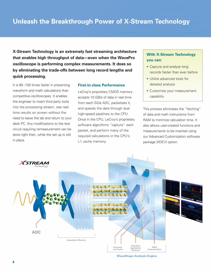
Processorand Cache
XDEVCustomization
StandardApplication
Routines
Acquisition Memory
WaveShape Analysis Engine
ADC
It is 80 –150 times faster in presenting
waveform and math calculations than
competitive oscilloscopes. It enables
the engineer to insert third party tools
into the processing stream, see real-
time results on screen without the
need to leave the lab and return to your
desk PC. Any modifications to the test
circuit requiring remeasurement can be
done right then, while the set up is still
in place.
First-in-class Performance
LeCroy’s proprietary CMOS memory
accepts 10 GB/s of data in real time
from each SiGe ADC, packetizes it,
and speeds the data through dual
high-speed pipelines to the CPU.
Once in the CPU, LeCroy’s proprietary
software algorithms “capture” each
packet, and perform many of the
required calculations in the CPU’s
L1 cache memory.
This process eliminates the “fetching”
of data and math instructions from
RAM to minimize calculation time. It
also allows user-created functions and
measurements to be inserted using
our Advanced Customization software
package (XDEV) option.
X-Stream Technology is an extremely fast streaming architecture
that enables high throughput of data—even when the WavePro
oscilloscope is performing complex measurements. It does so
by eliminating the trade-offs between long record lengths and
quick processing.
With X-Stream Technology
you can:
• Capture and analyze long
records faster than ever before
• Utilize advanced tools for
detailed analysis
• Customize your measurement
capability
5
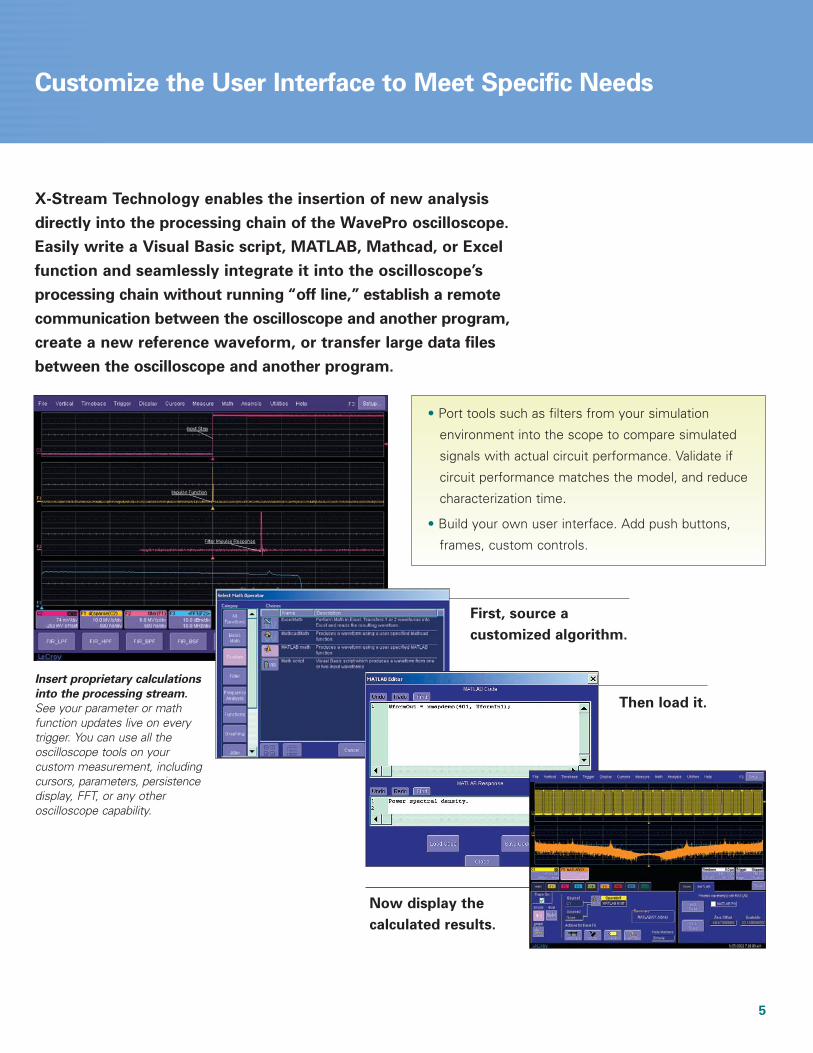
Customize the User Interface to Meet Specific Needs
First, source a
customized algorithm.
Then load it.
Now display the
calculated results.
Insert proprietary calculations
into the processing stream.
See your parameter or mathfunction updates live on everytrigger. You can use all the oscilloscope tools on your custom measurement, includingcursors, parameters, persistencedisplay, FFT, or any other oscilloscope capability.
• Port tools such as filters from your simulation
environment into the scope to compare simulated
signals with actual circuit performance. Validate if
circuit performance matches the model, and reduce
characterization time.
• Build your own user interface. Add push buttons,
frames, custom controls.
X-Stream Technology enables the insertion of new analysis
directly into the processing chain of the WavePro oscilloscope.
Easily write a Visual Basic script, MATLAB, Mathcad, or Excel
function and seamlessly integrate it into the oscilloscope’s
processing chain without running “off line,” establish a remote
communication between the oscilloscope and another program,
create a new reference waveform, or transfer large data files
between the oscilloscope and another program.
6
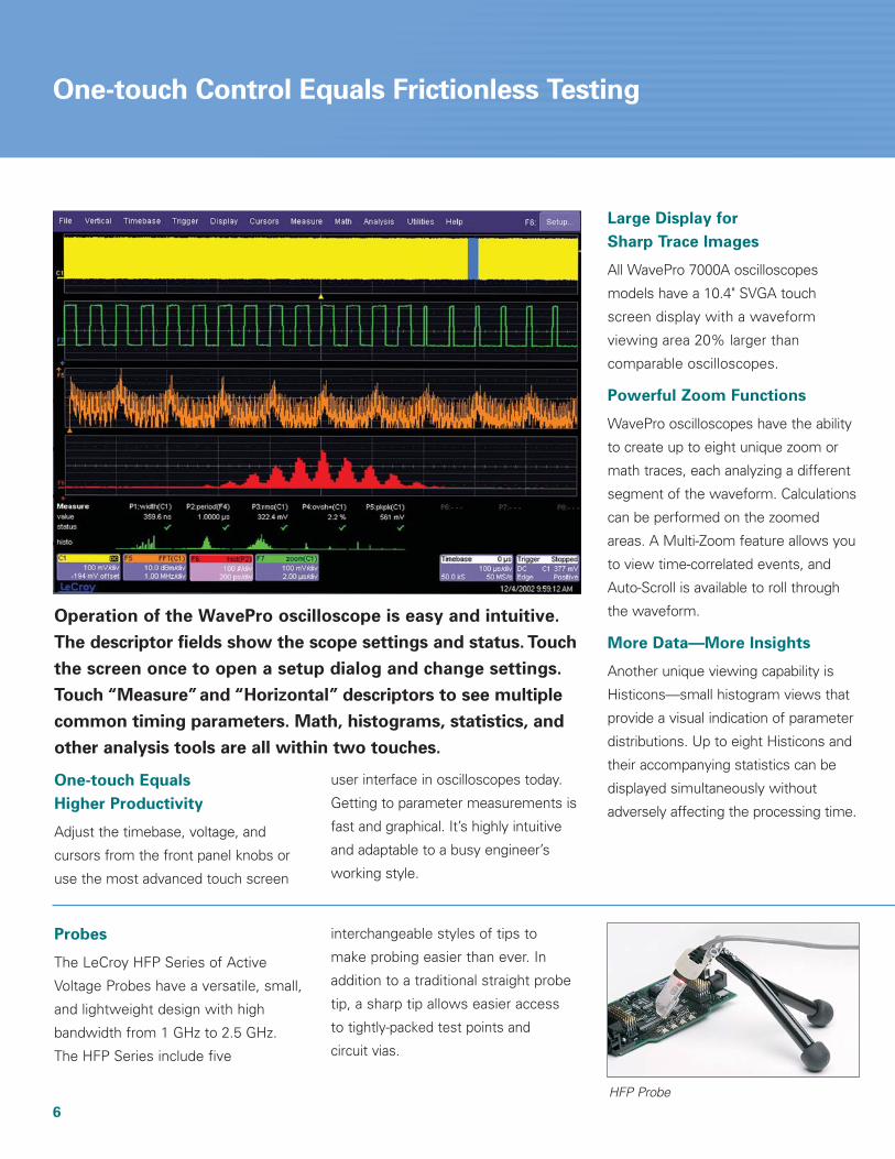
One-touch Control Equals Frictionless Testing
One-touch Equals
Higher Productivity
Adjust the timebase, voltage, and
cursors from the front panel knobs or
use the most advanced touch screen
user interface in oscilloscopes today.
Getting to parameter measurements is
fast and graphical. It’s highly intuitive
and adaptable to a busy engineer’s
working style.
Large Display for
Sharp Trace Images
All WavePro 7000A oscilloscopes
models have a 10.4" SVGA touch
screen display with a waveform
viewing area 20% larger than
comparable oscilloscopes.
Powerful Zoom Functions
WavePro oscilloscopes have the ability
to create up to eight unique zoom or
math traces, each analyzing a different
segment of the waveform. Calculations
can be performed on the zoomed
areas. A Multi-Zoom feature allows you
to view time-correlated events, and
Auto-Scroll is available to roll through
the waveform.
More Data—More Insights
Another unique viewing capability is
Histicons—small histogram views that
provide a visual indication of parameter
distributions. Up to eight Histicons and
their accompanying statistics can be
displayed simultaneously without
adversely affecting the processing time.
Operation of the WavePro oscilloscope is easy and intuitive.
The descriptor fields show the scope settings and status. Touch
the screen once to open a setup dialog and change settings.
Touch “Measure”and “Horizontal” descriptors to see multiple
common timing parameters. Math, histograms, statistics, and
other analysis tools are all within two touches.
Probes
The LeCroy HFP Series of Active
Voltage Probes have a versatile, small,
and lightweight design with high
bandwidth from 1 GHz to 2.5 GHz.
The HFP Series include five
interchangeable styles of tips to
make probing easier than ever. In
addition to a traditional straight probe
tip, a sharp tip allows easier access
to tightly-packed test points and
circuit vias.
HFP Probe

Advanced Math Software
Package (XMATH)
It provides more than 30 math functions
and 40 parameter measurements.
Advanced Customization
Software Package (XDEV)
This package allows you to create your
own scripts for measurement parame-
ters or math functions using third-party
software packages such as Excel,
MATLAB, and Mathcad.
Jitter and Timing Analysis
Software Package (JTA2)
This package shows modulation
effects and intermittent signal jitter to
track timing changes, and to debug in
the time, frequency, and statistical
domains. Views like Jitter Track and
Jitter Histogram let you see system
variability in ways that you have never
imagined.
Master Analysis Software
Package (XMAP)
It provides maximum capability and
flexibility, and includes all the functional-
ity present in XMATH, XDEV, and JTA2.
Digital Filter Software
Package (DFP2)
It lets you add any of a set of linear-
phase Finite Impulse Response (FIR)
filters. It enhances your ability to
examine important signal components
by filtering out undesired spectral
components such as noise. Use the
standard filters or create your own.
The Disk Drive Measurements
Software Package (DDM2)
This package adds dozens of new disk
drive measurements. DDM2, combined
with WavePro sequence triggering and
SMART Triggers®, offers the perfect
solution for failure analysis when test-
ing disk drives.
Advanced Optical Recording
Measurement Software
Package (AORM)
It provides 8 timing and 9 amplitude
analysis parameters for characterizing
CD/DVD and experimental optical
storage systems.
7
A Comprehensive Suite of Analysis Options
The WavePro 7000A Series takes WaveShape Analysis options
to a new level. The following software packages dramatically
expand the capabilities of WavePro oscilloscopes and enable
engineers to trouble-shoot circuits in more productive ways.
For differential measurements, the
WaveLink Series of high bandwidth
probes combine with WavePro to
complete the measurement system.
Best-in-class circuit loading character-
istics and exceptional frequency
response flatness accuracy maintain
signal fidelity through the entire
measurement system. AutoColorID
lights in the probe handle show
the channel trace color to quickly
identify which probe is driving which
channel. Visit www.lecroy.com for
more information.WaveLink D600ST
8
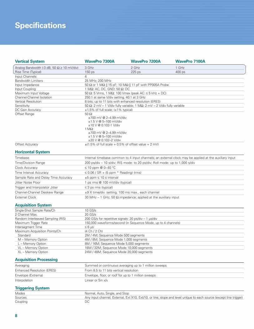
Specifications
Vertical System WavePro 7300A WavePro 7200A WavePro 7100A
Analog Bandwidth (-3 dB, 50 Ω ≥ 10 mV/div) 3 GHz 2 GHz 1 GHzRise Time (Typical) 150 ps 225 ps 400 psInput Channels 4Bandwidth Limiters 25 MHz; 200 MHzInput Impedance 50 Ω or 1 MΩ || 15 pF; 10 MΩ || 11 pF with PP005A ProbeInput Coupling 1 MΩ: AC, DC, GND; 50 Ω: DCMaximum Input Voltage 50 Ω: 5 Vrms, 1 MΩ: 100 Vmax (peak AC: ≤ 5 kHz + DC)Channel-Channel Isolation 250:1 at same V/div setting, 40:1 at 3 GHz Vertical Resolution 8 bits; up to 11 bits with enhanced resolution (ERES) Sensitivity 50 Ω: 2 mV – 1 V/div fully variable; 1 MΩ: 2 mV – 2 V/div fully variableDC Gain Accuracy ±1.5% of full scale; (±1% typical)Offset Range 50 Ω:
±700 mV @ 2–4.99 mV/div±1.5 V @ 5–100 mV/div±10 V @ 0.102-1 V/div
1 MΩ:±700 mV @ 2–4.99 mV/div±1.5 V @ 5–100 mV/div±20 V @ 0.102–2 V/div
Offset Accuracy ±(1.5% of full scale + 0.5% of offset value + 2 mV)
Horizontal System
Timebase Internal timebase common to 4 input channels; an external clock may be applied at the auxiliary inputTime/Division Range 200 ps/div – 10 s/div; RIS mode: to 20 ps/div; Roll mode: up to 1,000 s/div Clock Accuracy ≤ 10 ppm @ 0–40 °CTime Interval Accuracy ≤ 0.06 / SR + (5 ppm * Reading) (rms)Sample Rate and Delay Time Accuracy ±5 ppm ≤ 10 s intervalJitter Noise Floor 1 ps rms @ 100 mV/div (typical)Trigger and Interpolator Jitter ≤ 3 ps rms (typical)Channel-Channel Deskew Range ±9 X time/div. setting, 100 ms max., each channelExternal Clock 30 MHz – 1 GHz; 50 Ω impedance; applied at the auxiliary input
Acquisition System
Single-Shot Sample Rate/Ch 10 GS/s2 Channel Max. 20 GS/sRandom Interleaved Sampling (RIS) 200 GS/s for repetitive signals: 20 ps/div – 1 µs/divMaximum Trigger Rate 150,000 waveforms/second (in Sequence Mode, up to 4 channels)Intersegment Time ≤ 6 µsMaximum Acquisition Points/Ch (4 Ch / 2 Ch)
Standard 2M / 4M; Sequence Mode 500 segmentsM – Memory Option 4M / 8M; Sequence Mode 1,000 segmentsL – Memory Option 8M / 16M; Sequence Mode 5,000 segmentsVL – Memory Option 16M / 32M; Sequence Mode 10,000 segmentsXL – Memory Option 24M / 48M; Sequence Mode 20,000 segments
Acquisition Processing
Averaging Summed or continuous averaging up to 1 million sweepsEnhanced Resolution (ERES) From 8.5 to 11 bits vertical resolutionEnvelope (Extrema) Envelope, floor, or roof for up to 1 million sweepsInterpolation Linear or Sin x/x
Triggering System
Modes Normal, Auto, Single, and StopSources Any input channel, External, Ext X10, Ext/10, or line; slope and level unique to each source (except line trigger)Coupling DC
9
Specifications
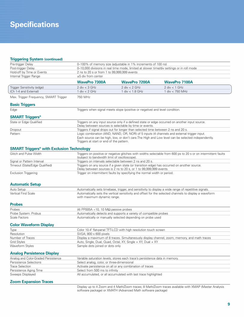
Triggering System (continued)
Pre-trigger Delay 0–100% of memory size (adjustable in 1% increments of 100 ns)Post-trigger Delay 0–10,000 divisions in real time mode, limited at slower time/div settings or in roll modeHold-off by Time or Events 2 ns to 20 s or from 1 to 99,999,999 eventsInternal Trigger Range ±5 div from center
WavePro 7300A WavePro 7200A WavePro 7100A
Trigger Sensitivity (edge) 2 div < 3 GHz 2 div < 2 GHz 2 div < 1 GHz (Ch 1-4 and External) 1 div < 2 GHz 1 div < 1.8 GHz 1 div < 750 MHz
Max. Trigger Frequency, SMART Trigger 750 MHz
Basic Triggers
Edge Triggers when signal meets slope (positive or negative) and level condition.
SMART Triggers®
State or Edge Qualified Triggers on any input source only if a defined state or edge occurred on another input source.Delay between sources is selectable by time or events.
Dropout Triggers if signal drops out for longer than selected time between 2 ns and 20 s.Pattern Logic combination (AND, NAND, OR, NOR) of 5 inputs (4 channels and external trigger input.
Each source can be high, low, or don’t care.The High and Low level can be selected independently.Triggers at start or end of the pattern.
SMART Triggers® with Exclusion Technology
Glitch and Pulse Width Triggers on positive or negative glitches with widths selectable from 600 ps to 20 s or on intermittent faults (subject to bandwidth limit of oscilloscope).
Signal or Pattern Interval Triggers on intervals selectable between 2 ns and 20 s.Timeout (State/Edge Qualified) Triggers on any source if a given state (or transition edge) has occurred on another source.
Delay between sources is 2 ns to 20 s, or 1 to 99,999,999 events.Exclusion Triggering Trigger on intermittent faults by specifying the normal width or period.
Automatic Setup
Auto Setup Automatically sets timebase, trigger, and sensitivity to display a wide range of repetitive signals.Vertical Find Scale Automatically sets the vertical sensitivity and offset for the selected channels to display a waveform
with maximum dynamic range.
Probes
Probes (4) PP005A ÷10, 10 MΩ passive probesProbe System: Probus Automatically detects and supports a variety of compatible probesScale Factors Automatically or manually selected depending on probe used
Color Waveform Display
Type Color 10.4" flat-panel TFT-LCD with high resolution touch screenResolution SVGA; 800 x 600 pixelsNumber of Traces Display a maximum of 8 traces. Simultaneously display channel, zoom, memory, and math tracesGrid Styles Auto, Single, Dual, Quad, Octal, XY, Single + XY, Dual + XYWaveform Styles Sample dots joined or dots only
Analog Persistence Display
Analog and Color-Graded Persistence Variable saturation levels; stores each trace’s persistence data in memory.Persistence Selections Select analog, color, or three-dimensionalTrace Selection Activate persistence on all or any combination of tracesPersistence Aging Time Select from 500 ms to infinitySweeps Displayed All accumulated, or all accumulated with last trace highlighted
Zoom Expansion Traces
Display up to 4 Zoom and 4 Math/Zoom traces; 8 Math/Zoom traces available with XMAP (Master Analysis software package) or XMATH (Advanced Math software package)
10
Specifications
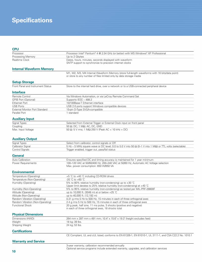
CPU
Processor Processor Intel® Pentium® 4 @ 2.54 GHz (or better) with MS Windows® XP ProfessionalProcessing Memory Up to 2 GbytesRealtime Clock Dates, hours, minutes, seconds displayed with waveform
SNTP support to synchronize to precision internet clocks
Internal Waveform Memory
M1, M2, M3, M4 Internal Waveform Memory (store full-length waveforms with 16 bits/data point)or store to any number of files limited only by data storage media
Setup Storage
Front Panel and Instrument Status Store to the internal hard drive, over a network or to a USB-connected peripheral device
Interface
Remote Control Via Windows Automation, or via LeCroy Remote Command SetGPIB Port (Optional) Supports IEEE – 488.2Ethernet Port 10/100Base-T Ethernet interfaceUSB Ports USB 2.0 ports support Windows compatible devicesExternal Monitor Port Standard 15-pin D-Type SVGA-compatibleParallel Port 1 standard
Auxiliary Input
Signal Types Selected from External Trigger or External Clock input on front panelCoupling 50 Ω: DC; 1 MΩ: AC, DC, GNDMax. Input Voltage 50 Ω: 5 V rms; 1 MΩ 250 V (Peak AC < 10 kHz + DC)
Auxiliary Output
Signal Types Select from calibrator, control signals or OffCalibrator Signal 5 Hz – 5 MHz square wave or DC level; 0.0 to 5.0 V into 50 Ω (0–1 V into 1 MΩ) or TTL volts (selectable)Control Signals Trigger enabled, trigger out, pass/fail status
General
Auto Calibration Ensures specified DC and timing accuracy is maintained for 1 year minimumPower Requirements 100–120 VAC at 50/60/400 Hz; 200–240 VAC at 50/60 Hz; Automatic AC Voltage selection
Max. power consumption: 650 W/650 VA
Environmental
Temperature (Operating) +5 ˚C to +40 ˚C including CD-ROM drivesTemperature (Non-Operating) -20 ˚C to +60 ˚CHumidity (Operating) 5% to 80% relative humidity (non-condensing) up to +30 ˚C
Upper limit derates to 25% relative humidity (non-condensing) at +40 ˚CHumidity (Non-Operating) 5% to 95% relative humidity (non-condensing) as tested per MIL-PRF-28800FAltitude (Operating) up to 10,000 ft. (3048 m) at or below +25 ˚CAltitude (Non-Operating) up to 40,000 ft. (12,192 m)Random Vibration (Operating) 0.31 g rms 5 Hz to 500 Hz, 15 minutes in each of three orthogonal axesRandom Vibration (Non-Operating) 2.4 g rms 5 Hz to 500 Hz, 15 minutes in each of three orthogonal axesFunctional Shock 20 g peak, half sine, 11 ms pulse, 3 shocks (positive and negative)
in each of three orthogonal axes, 18 shocks total
Physical Dimensions
Dimensions (HWD) 264 mm x 397 mm x 491 mm; 10.4" x 15.6" x 19.3" (height excludes feet)Weight 18 kg; 39 lbs.Shipping Weight 24 kg; 53 lbs.
Certifications
CE Compliant, UL and cUL listed; conforms to EN 61326-1, EN 61010-1, UL 3111-1, and CSA C22.2 No. 1010.1
Warranty and Service
3-year warranty; calibration recommended annuallyOptional service programs include extended warranty, upgrades, and calibration services
11
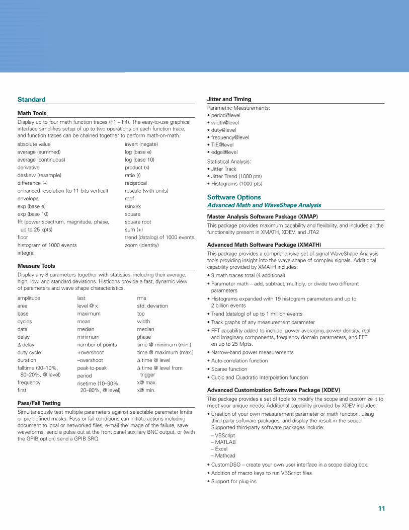
Standard
Math Tools
Display up to four math function traces (F1 – F4). The easy-to-use graphicalinterface simplifies setup of up to two operations on each function trace,and function traces can be chained together to perform math-on-math.
absolute value invert (negate)average (summed) log (base e)average (continuous) log (base 10)derivative product (x)deskew (resample) ratio (/)difference (–) reciprocalenhanced resolution (to 11 bits vertical) rescale (with units)envelope roofexp (base e) (sinx)/xexp (base 10) squarefft (power spectrum, magnitude, phase, square root
up to 25 kpts) sum (+)floor trend (datalog) of 1000 eventshistogram of 1000 events zoom (identity)integral
Measure Tools
Display any 8 parameters together with statistics, including their average,high, low, and standard deviations. Histicons provide a fast, dynamic view of parameters and wave shape characteristics.
Pass/Fail Testing
Simultaneously test multiple parameters against selectable parameter limitsor pre-defined masks. Pass or fail conditions can initiate actions includingdocument to local or networked files, e-mail the image of the failure, savewaveforms, send a pulse out at the front panel auxiliary BNC output, or (withthe GPIB option) send a GPIB SRQ.
Jitter and Timing
Parametric Measurements:• period@level• width@level• duty@level• frequency@level• TIE@level• edge@level
Statistical Analysis:• Jitter Track• Jitter Trend (1000 pts)• Histograms (1000 pts)
Software OptionsAdvanced Math and WaveShape Analysis
Master Analysis Software Package (XMAP)
This package provides maximum capability and flexibility, and includes all thefunctionality present in XMATH, XDEV, and JTA2
Advanced Math Software Package (XMATH)
This package provides a comprehensive set of signal WaveShape Analysistools providing insight into the wave shape of complex signals. Additionalcapability provided by XMATH includes:
• 8 math traces total (4 additional)
• Parameter math – add, subtract, multiply, or divide two different parameters
• Histograms expanded with 19 histogram parameters and up to 2 billion events
• Trend (datalog) of up to 1 million events
• Track graphs of any measurement parameter
• FFT capability added to include: power averaging, power density, real and imaginary components, frequency domain parameters, and FFT on up to 25 Mpts.
• Narrow-band power measurements
• Auto-correlation function
• Sparse function
• Cubic and Quadratic Interpolation function
Advanced Customization Software Package (XDEV)
This package provides a set of tools to modify the scope and customize it tomeet your unique needs. Additional capability provided by XDEV includes:
• Creation of your own measurement parameter or math function, usingthird-party software packages, and display the result in the scope. Supported third-party software packages include:
– VBScript– MATLAB– Excel– Mathcad
• CustomDSO – create your own user interface in a scope dialog box.
• Addition of macro keys to run VBScript files
• Support for plug-ins
amplitudeareabasecyclesdatadelay∆ delayduty cycledurationfalltime (90–10%,
80–20%, @ level)frequencyfirst
lastlevel @ xmaximummeanmedianminimumnumber of points+overshoot–overshootpeak-to-peakperiodrisetime (10–90%,
20–80%, @ level)
rmsstd. deviationtopwidthmedianphasetime @ minimum (min.)time @ maximum (max.)∆ time @ level∆ time @ level from
triggerx@ max.x@ min.

12
Jitter and Timing Analysis Software Package (JTA2)
This package provides jitter timing and analysis using time, frequency, andstatistical views for common timing parameters, and also includes otheruseful tools. JTA2 includes:
• Jitter and timing parameters, with “Track” graphs of
• Edge@lv parameter (counts edges)
• Histograms expanded with 19 histogram parameters and up to 2 billion events
• Trend (datalog) of up to 1 million events
• Track graphs of all parameters
• Persistence histogram, persistence trace (mean, range, sigma)
Digital Filter Software Package (DFP2)
LeCroy’s Digital Filter Package (DFP2) implements a set of linear-phaseFinite Impulse Response (FIR) filters and IIR filters. It enhances the user’sability to examine important signal components by filtering out undesiredspectral components such as noise. With the custom design feature,corrupted signals can be reconstructed by applying matched (mirror) filtersto compensate for known distortions.
The DFP2 option has a broad range of applications:
– System Identification– Prediction– Noise Cancellation– Low-pass Filters– Band-stop Filters– Band-pass Filters– High-pass Filters– Raised Cosine, Raised Root Cosine, and Gaussian Filters
Application Specific Test and Analysis Packages
Power Measure Analysis Package (PMA2)
This package provides exceptional ability to measure and analyze theoperating characteristics of power conversion devices and circuits.
– Automatic setup and display of relevant waveforms and parameters– Waveforms scaled and displayed in volts, amps, watts, ohms, etc.– Power device performance analyzed in-circuit– Measure and view time domain response of the entire control loop– Pre-compliance line harmonic testing to EN 61000-3-2– Complete solutions available including probes and differential amplifiers
– Cycle-Cycle Jitter– N-Cycle– N-Cycle with start
selection– Frequency
– Period– Half Period– Width– Time Interval Error– Setup
– Hold– Skew– Duty Cycle– Duty Cycle Error
Advanced Optical Recording Measurements (AORM)
The AORM option in our new-generation X-Stream oscilloscope environ-ment provides a completely updated user interface and improved debugtools written to support ever-increasing read/write data rates and largermedia capacity required for the latest CD and DVD implementations.Typical applications include game box technology and high-capacity DVD Read/Write.
The unique combination of deep acquisition memory available in LeCroyoscilloscopes and the flexibility of AORM in adapting to optical recordingstandards provides the user with ultimate measurement accuracy and 2-dimensional correlation of recording parameters.Note: AORM is supported in WavePro 7200A oscilloscopes and higher.
Parameter Definition Table
Timing Analysis Parameters Amplitude Analysis Parameters
deltap2c Data edge shift referred paa Average amplitude ofto clock RF signal
deltap2cs Standard deviation of pasym Asymmetry of RF signaldeltap2c
edgsh Pit or space width pbase Base of pit or spacedifference fromideal value
period Period of each cycle pmax Maximum of pit or spaceof clock
pnum Number of pit or pmidl Middle voltage of pit or space pair space
pwid Width of pit or pmin Minimum of pit or spacespace pairs
t@pit Delay of pit or space pmoda Modulation of RF signalfrom trigger
timj Standard deviation pres Resolution of RF signalof edgsh
ptop Top of pit or space
Disk Drive Measurements Package (DDM2)
This package provides disk drive parameter measurements and related math-ematical functions for performing disk drive WaveShape Analysis.
• Disk Drive Parameters are as follows:
• Correlation function
• Trend (datalog) of up to 1 million events
• Histograms expanded with 18 histogram parameters and up to 2 billion events
amplitude assymetrylocal baselocal baseline separationlocal maximumlocal minimumlocal numberlocal peak-peaklocal time between eventslocal time between peakslocal time between troughslocal time at minimumlocal time at maximumlocal time peak-troughlocal time over threshold
local time trough-peaklocal time under thresholdnarrow band phasenarrow band poweroverwritepulse width 50pulse width 50–pulse width 50+resolutiontrack average amplitudetrack average amplitude–track average amplitude+auto-correlation s/nnon-linear transition shift
13
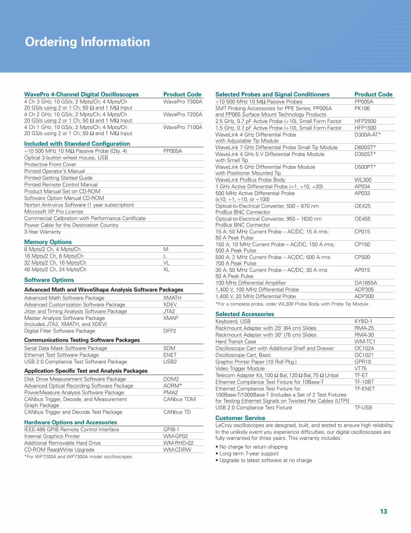
Ordering Information
WavePro 4-Channel Digital Oscilloscopes Product Code
4 Ch 3 GHz; 10 GS/s; 2 Mpts/Ch; 4 Mpts/Ch WavePro 7300A20 GS/s using 2 or 1 Ch; 50 Ω and 1 MΩ Input4 Ch 2 GHz; 10 GS/s; 2 Mpts/Ch; 4 Mpts/Ch WavePro 7200A20 GS/s using 2 or 1 Ch; 50 Ω and 1 MΩ Input4 Ch 1 GHz; 10 GS/s; 2 Mpts/Ch; 4 Mpts/Ch WavePro 7100A20 GS/s using 2 or 1 Ch; 50 Ω and 1 MΩ Input
Included with Standard Configuration
÷10 500 MHz 10 MΩ Passive Probe (Qty. 4) PP005AOptical 3 button wheel mouse, USBProtective Front CoverPrinted Operator’s ManualPrinted Getting Started GuidePrinted Remote Control ManualProduct Manual Set on CD-ROMSoftware Option Manual CD-ROMNorton Anti-virus Software (1 year subscription)Microsoft XP Pro LicenseCommercial Calibration with Performance CertificatePower Cable for the Destination Country3-Year Warranty
Memory Options
8 Mpts/2 Ch, 4 Mpts/Ch M16 Mpts/2 Ch, 8 Mpts/Ch L32 Mpts/2 Ch, 16 Mpts/Ch VL48 Mpts/2 Ch, 24 Mpts/Ch XL
Software Options
Advanced Math and WaveShape Analysis Software Packages
Advanced Math Software Package XMATHAdvanced Customization Software Package XDEVJitter and Timing Analysis Software Package JTA2Master Analysis Software Package XMAP(Includes JTA2, XMATH, and XDEV)Digital Filter Software Package DFP2
Communications Testing Software Packages
Serial Data Mask Software Package SDMEthernet Test Software Package ENETUSB 2.0 Compliance Test Software Package USB2
Application Specific Test and Analysis Packages
Disk Drive Measurement Software Package DDM2Advanced Optical Recording Software Package AORM*PowerMeasure Analysis Software Package PMA2CANbus Trigger, Decode, and Measurement CANbus TDMGraph PackageCANbus Trigger and Decode Test Package CANbus TD
Hardware Options and Accessories
IEEE-488 GPIB Remote Control Interface GPIB-1Internal Graphics Printer WM-GP02Additional Removable Hard Drive WM-RHD-02CD-ROM Read/Write Upgrade WM-CDRW*For WP7200A and WP7300A model oscilloscopes.
Selected Probes and Signal Conditioners Product Code
÷10 500 MHz 10 MΩ Passive Probes PP005ASMT Probing Accessories for PPE Series, PP005A PK106and PP065 Surface Mount Technology Products2.5 GHz, 0.7 pF Active Probe (÷10), Small Form Factor HFP25001.5 GHz, 0.7 pF Active Probe (÷10), Small Form Factor HFP1500WaveLink 4 GHz Differential Probe D300A-AT*with Adjustable Tip ModuleWaveLink 7 GHz Differential Probe Small Tip Module D600ST*WaveLink 4 GHz 5 V Differential Probe Module D350ST*with Small TipWaveLink 5 GHz Differential Probe Module D500PT*with Positioner Mounted TipWaveLink ProBus Probe Body WL3001 GHz Active Differential Probe (÷1, ÷10, ÷20) AP034500 MHz Active Differential Probe AP033(x10, ÷1, ÷10, or ÷100)Optical-to-Electrical Converter, 500 – 870 nm OE425ProBus BNC ConnectorOptical-to-Electrical Converter, 950 – 1630 nm OE455ProBus BNC Connector15 A; 50 MHz Current Probe – AC/DC; 15 A rms; CP01550 A Peak Pulse150 A; 10 MHz Current Probe – AC/DC; 150 A rms; CP150500 A Peak Pulse500 A; 2 MHz Current Probe – AC/DC; 500 A rms CP500700 A Peak Pulse30 A; 50 MHz Current Probe – AC/DC; 30 A rms AP01550 A Peak Pulse100 MHz Differential Amplifier DA1855A1,400 V, 100 MHz Differential Probe ADP3051,400 V, 20 MHz Differential Probe ADP300*For a complete probe, order WL300 Probe Body with Probe Tip Module
Selected Accessories
Keyboard, USB KYBD-1Rackmount Adapter with 25" (64 cm) Slides RMA-25Rackmount Adapter with 30" (76 cm) Slides RMA-30Hard Transit Case WM-TC1Oscilloscope Cart with Additional Shelf and Drawer OC1024Oscilloscope Cart, Basic OC1021Graphic Printer Paper (10 Roll Pkg.) GPR10Video Trigger Module VT75Telecom Adapter Kit,100 Ω Bal,120 Ω Bal,75 Ω Unbal TF-ETEthernet Compliance Test Fixture for 10Base-T TF-10BTEthernet Compliance Test Fixture for TF-ENET100Base-T/1000Base-T [Includes a Set of 2 Test Fixtures for Testing Ethernet Signals on Twisted Pair Cables (UTP)] USB 2.0 Compliance Test Fixture TF-USB
Customer Service
LeCroy oscilloscopes are designed, built, and tested to ensure high reliability.In the unlikely event you experience difficulties, our digital oscilloscopes arefully warranted for three years. This warranty includes:
• No charge for return shipping • Long term 7-year support • Upgrade to latest software at no charge

1-800-5-LeCroywww.lecroy.com
DCWP WEB1 05/05
Local sales offices are located throughout the world.
To find the most convenient one visit www.lecroy.com
© 2005 by LeCroy Corporation. All rights reserved. Specifications subject to change without notice.Other product or brand names are trademarks or requested trademarks of their respective holders.