
Vortex Induced Forces - MITweb.mit.edu/13.42/www/handouts/2003/VIV_II_notes.pdf• Harmonically...
15
13.42 Lecture VIV II Alex Techet March 18, 2003 Vortex Induced Forces Due to unsteady flow, forces, X(t) and Y(t), vary with time. Force coefficients: C x = C y = X(t) 1 / 2 ρ U 2 d Y(t) 1 / 2 ρ U 2 d Force Time Trace C x C y DRAG LIFT
Transcript of Vortex Induced Forces - MITweb.mit.edu/13.42/www/handouts/2003/VIV_II_notes.pdf• Harmonically...
1
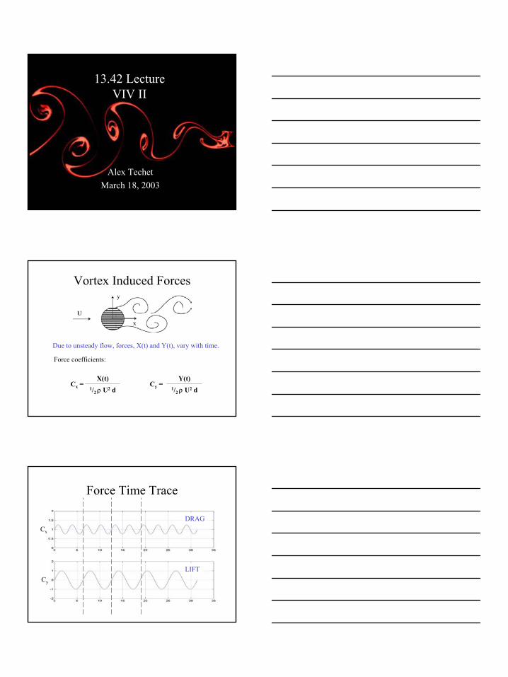
13.42 LectureVIV II
Alex TechetMarch 18, 2003
Vortex Induced Forces
Due to unsteady flow, forces, X(t) and Y(t), vary with time.
Force coefficients:
Cx = Cy = X(t)
1/2 ρ U2 d
Y(t)1/2 ρ U2 d
Force Time Trace
Cx
Cy
DRAG
LIFT
2
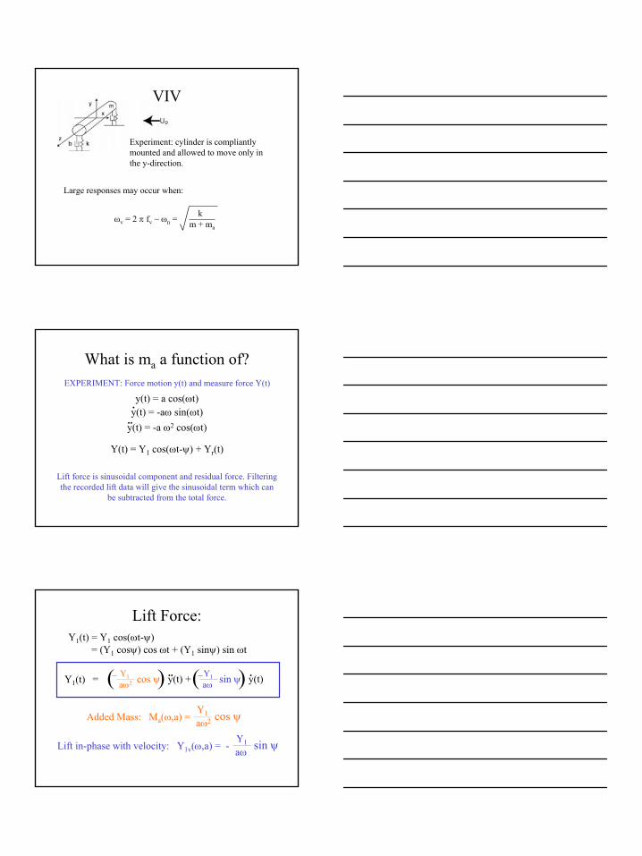
VIV
Experiment: cylinder is compliantly mounted and allowed to move only in the y-direction.
Large responses may occur when:
ωv = 2 π fv ~ ωn = km + ma
What is ma a function of?EXPERIMENT: Force motion y(t) and measure force Y(t)
y(t) = a cos(ωt)
Y(t) = Y1 cos(ωt-ψ) + Yr(t)
y(t) = -aω sin(ωt).
..y(t) = -a ω2 cos(ωt)
Lift force is sinusoidal component and residual force. Filteringthe recorded lift data will give the sinusoidal term which can
be subtracted from the total force.
Lift Force:Y1(t) = Y1 cos(ωt-ψ)
= (Y1 cosψ) cos ωt + (Y1 sinψ) sin ωt
Y1aω2= cos ψ y(t) + sin ψ y(t)Y1
aω( () ).. .
Added Mass: Ma(ω,a) =Y1aω2 cos ψ
Lift in-phase with velocity: Y1v(ω,a) = -Y1aω
sin ψ
Y1(t)
3
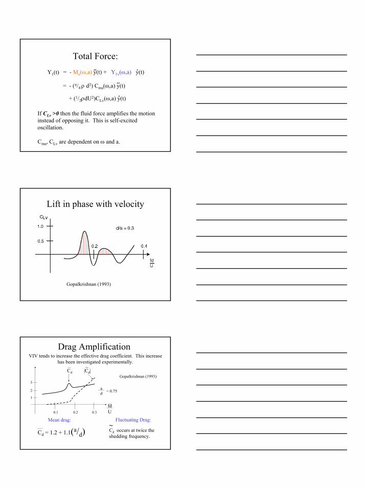
Total Force:= - Ma(ω,a) y(t) + Y1v(ω,a) y(t).. .Y1(t)
= - (π/4 ρ d2) Cma(ω,a) y(t)
+ (1/2ρdU2)CLv(ω,a) y(t)
..
.
If CLv >0 then the fluid force amplifies the motion instead of opposing it. This is self-excited oscillation.
Cma, CLv are dependent on ω and a.
Lift in phase with velocity
Gopalkrishnan (1993)
Drag Amplification
Gopalkrishnan (1993)
Cd = 1.2 + 1.1(a/d)
VIV tends to increase the effective drag coefficient. This increase has been investigated experimentally.
Mean drag: Fluctuating Drag:
Cd occurs at twice the shedding frequency.
~
3
2
1
Cd |Cd|~
0.1 0.2 0.3
fdU
ad = 0.75
4
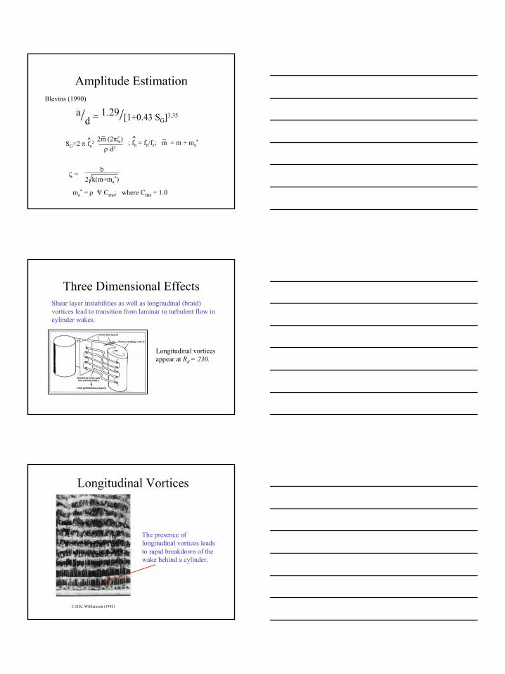
Amplitude Estimation
ζ = b
2 k(m+ma*)
ma* = ρ V Cma; where Cma = 1.0
Blevins (1990)
a/d = 1.29/[1+0.43 SG]3.35~
SG=2 π fn2 2m (2πζ)
ρ d2; fn = fn/fs; m = m + ma
*^^ __
Three Dimensional EffectsShear layer instabilities as well as longitudinal (braid) vortices lead to transition from laminar to turbulent flow in cylinder wakes.
Longitudinal vortices appear at Rd = 230.
Longitudinal Vortices
C.H.K. Williamson (1992)
The presence of longitudinal vortices leads to rapid breakdown of the wake behind a cylinder.
5
Longitudinal Vortices
Strouhal Number for the tapered cylinder:
St = fd / U
where d is the average cylinder diameter.
Oscillating Tapered Cylinder
x
d(x)
U(x
) = U
o
Spanwise Vortex Shedding from 40:1 Tapered Cylinder
Tech
et, e
t al (
JFM
199
8)
dmax
Rd = 400; St = 0.198; A/d = 0.5
Rd = 1500; St = 0.198; A/d = 0.5
Rd = 1500; St = 0.198; A/d = 1.0
dminNo Split: ‘2P’

6
Flow Visualization Reveals: A Hybrid Shedding Mode
• ‘2P’ pattern results at the smaller end
• ‘2S’ pattern at the larger end
• This mode is seen to be repeatable over multiple cycles
Techet, et al (JFM 1998)
DPIV of Tapered Cylinder Wake
‘2S’
‘2P’
Digital particle image velocimetry (DPIV) in the horizontal plane leads to a clear picture of two distinct shedding modes along the cylinder.
Rd = 1500; St = 0.198; A/d = 0.5
z/d
= 22
.9z/
d =
7.9
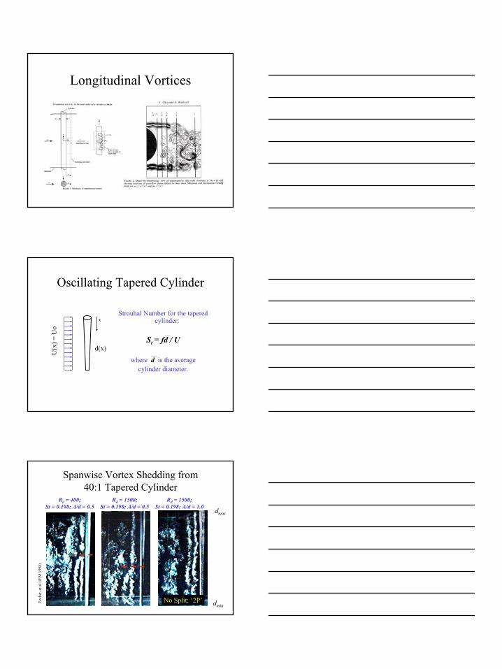
Evolution of the Hybrid Shedding Mode
‘2P’ ‘2S’
Rd = 1500; St = 0.198; A/d = 0.5
z/d = 22.9z/d = 7.9
7
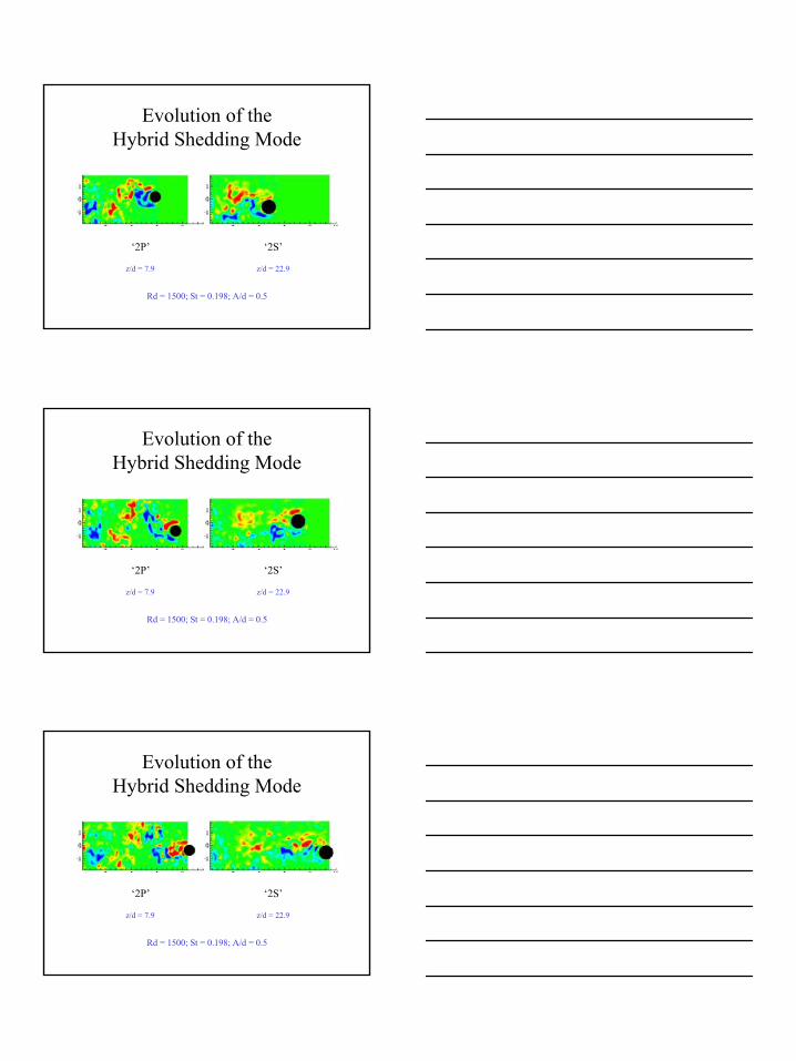
Evolution of the Hybrid Shedding Mode
‘2S’‘2P’
Rd = 1500; St = 0.198; A/d = 0.5
z/d = 22.9z/d = 7.9
Evolution of the Hybrid Shedding Mode
‘2S’‘2P’
Rd = 1500; St = 0.198; A/d = 0.5
z/d = 22.9z/d = 7.9
Evolution of the Hybrid Shedding Mode
‘2S’‘2P’
Rd = 1500; St = 0.198; A/d = 0.5
z/d = 22.9z/d = 7.9
8
NEKTAR-ALE Simulations
Objectives:• Confirm numerically the existence of a stable,
periodic hybrid shedding mode 2S~2P in the wake of a straight, rigid, oscillating cylinder
Principal Investigator:• Prof. George Em Karniadakis, Division of Applied
Mathematics, Brown University
Approach:• DNS - Similar conditions as the MIT experiment
(Triantafyllou et al.)• Harmonically forced oscillating straight rigid
cylinder in linear shear inflow• Average Reynolds number is 400
Vortex Dislocations, Vortex Splits & Force Distribution in Flows past Bluff Bodies
D. Lucor & G. E. Karniadakis
Results:• Existence and periodicity of hybrid mode
confirmed by near wake visualizations and spectral analysis of flow velocity in the cylinder wake and of hydrodynamic forces
Methodology:• Parallel simulations using spectral/hp methods
implemented in the incompressible Navier- Stokes solver NEKTAR
VORTEX SPLIT
Techet, Hover and Triantafyllou (JFM 1998)
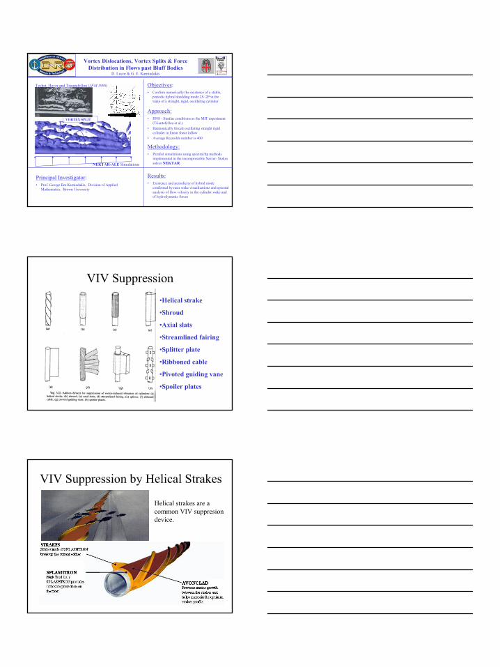
VIV Suppression•Helical strake
•Shroud
•Axial slats
•Streamlined fairing
•Splitter plate
•Ribboned cable
•Pivoted guiding vane
•Spoiler plates
VIV Suppression by Helical Strakes
Helical strakes are a common VIV suppresiondevice.
9
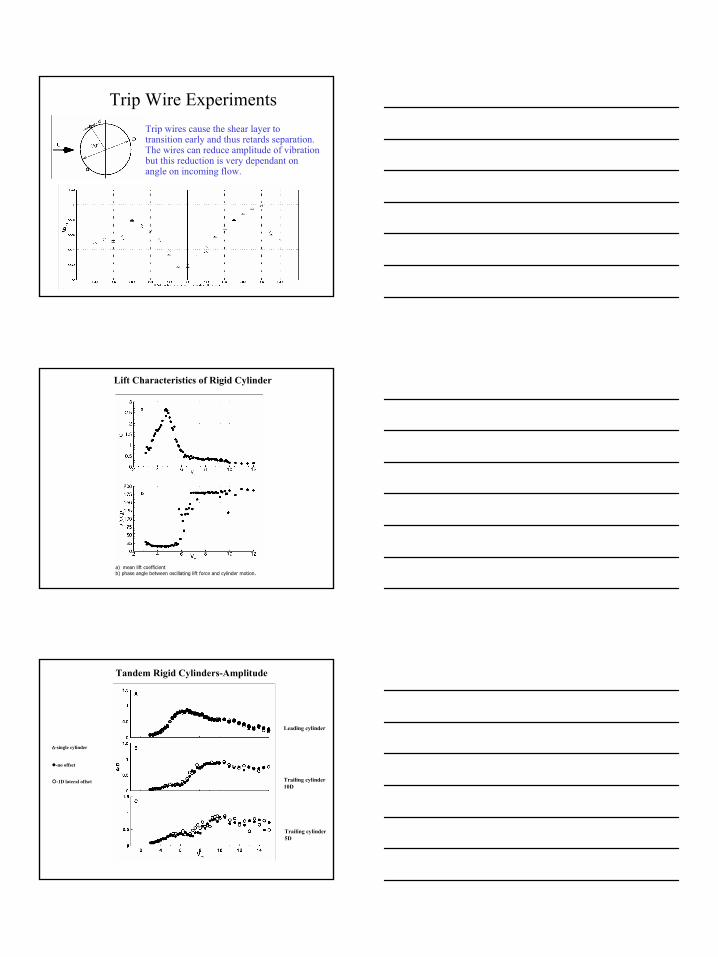
Trip Wire ExperimentsTrip wires cause the shear layer to transition early and thus retards separation. The wires can reduce amplitude of vibration but this reduction is very dependant on angle on incoming flow.
Lift Characteristics of Rigid Cylinder
a) mean lift coefficientb) phase angle between oscillating lift force and cylinder motion.
Tandem Rigid Cylinders-Amplitude
Leading cylinder
Trailing cylinder10D
Trailing cylinder5D
∆-single cylinder
-no offset
-1D lateral offset
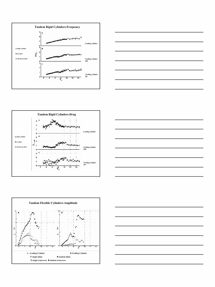
10
∆-single cylinder
-no offset
-1D lateral offset
Leading cylinder
Trailing cylinder10D
Trailing cylinder5D
Tandem Rigid Cylinders-Frequency
Leading cylinder
Trailing cylinder10D
Trailing cylinder5D
∆-single cylinder
-no offset
-1D lateral offset
Tandem Rigid Cylinders-Drag
Tandem Flexible Cylinders-Amplitude
A - Leading Cylinder B-Trailing Cylinder
∇-single inline -tandem inline
-single transverse -tandem transverse
11
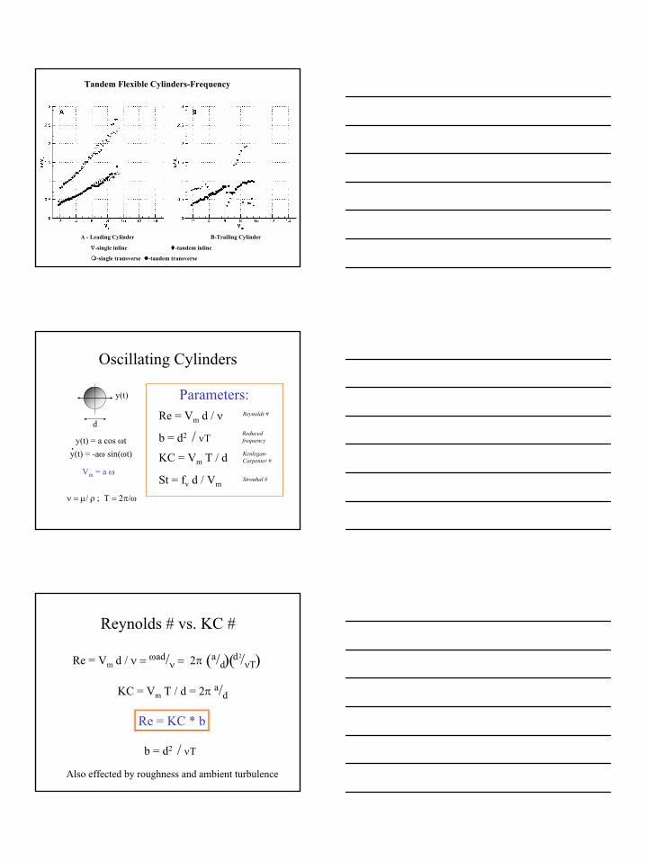
Tandem Flexible Cylinders-Frequency
A - Leading Cylinder B-Trailing Cylinder
∇-single inline -tandem inline
-single transverse -tandem transverse
Oscillating Cylinders
d
y(t)
y(t) = a cos ωt
Parameters:Re = Vm d / ν
Vm = a ω
y(t) = -aω sin(ωt).
b = d2 / νT
KC = Vm T / d
St = fv d / Vm
ν = µ/ ρ ; Τ = 2π/ω
Reducedfrequency
Keulegan-Carpenter #
Strouhal #
Reynolds #
Reynolds # vs. KC #
b = d2 / νT
KC = Vm T / d = 2π a/d
Re = Vm d / ν = ωad/ν = 2π a/d d /νΤ
2)(( )
Re = KC * b
Also effected by roughness and ambient turbulence
12
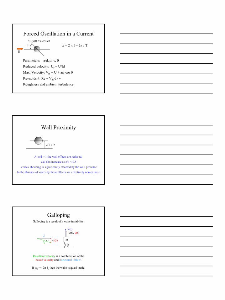
Forced Oscillation in a Current
θ
U
y(t) = a cos ωtω = 2 π f = 2π / T
Parameters: a/d, ρ, ν, θ
Reduced velocity: Ur = U/fd
Max. Velocity: Vm = U + aω cos θ
Reynolds #: Re = Vm d / ν
Roughness and ambient turbulence
Wall Proximity
e + d/2
At e/d > 1 the wall effects are reduced.
Cd, Cm increase as e/d < 0.5
Vortex shedding is significantly effected by the wall presence.
In the absence of viscosity these effects are effectively non-existent.
GallopingGalloping is a result of a wake instability.
m
y(t), y(t).Y(t)
U-y(t)
.V
α
Resultant velocity is a combination of the heave velocity and horizontal inflow.
If ωn << 2π fv then the wake is quasi-static.
13
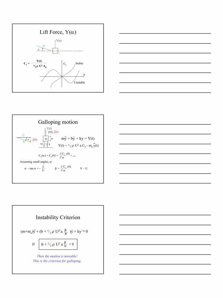
Lift Force, Y(α) Y(t)
Vα
Cy = Y(t)
1/2 ρ U2 Ap
α
Cy Stable
Unstable
Galloping motion
m
y(t), y(t).Y(t)
U-y(t)
.V
α
b k
a my + by + ky = Y(t).. .
Y(t) = 1/2 ρ U2 a Cy - ma y(t)..
Cy(α) = Cy(0) + ∂ Cy (0)∂ α
+ ...
Assuming small angles, α:
α ~ tan α = - yU
.β = ∂ Cy (0)
∂ α V ~ U
Instability Criterion
(m+ma)y + (b + 1/2 ρ U2 a )y + ky = 0.. .βU
~
b + 1/2 ρ U2 a βU < 0If
Then the motion is unstable!This is the criterion for galloping.
14
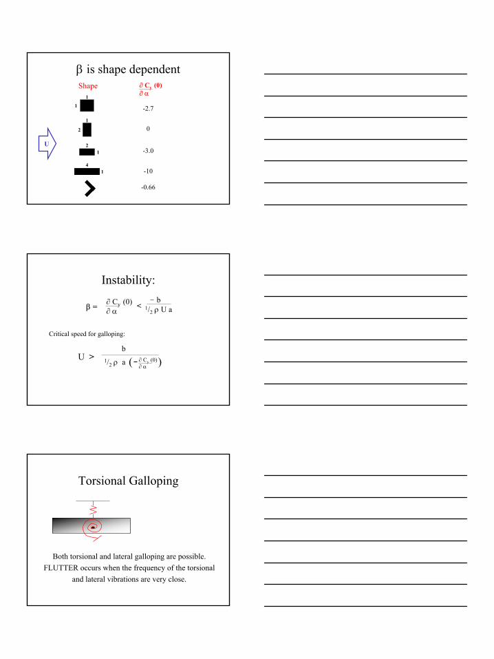
β is shape dependent
U
1
1
1
2
12
14
Shape ∂ Cy (0)∂ α
-2.7
0
-3.0
-10
-0.66
b1/2 ρ a ( )
Instability:
β = ∂ Cy (0)∂ α
<b
1/2 ρ U a
Critical speed for galloping:
U > ∂ Cy (0)∂ α
Torsional Galloping
Both torsional and lateral galloping are possible.FLUTTER occurs when the frequency of the torsional
and lateral vibrations are very close.
15
Galloping vs. VIV
• Galloping is low frequency
• Galloping is NOT self-limiting
• Once U > Ucritical then the instability occurs irregardless of frequencies.
References
• Blevins, (1990) Flow Induced Vibrations, Krieger Publishing Co., Florida.


![arXiv:math/0205184v2 [math.AP] 17 Jun 2002 › pdf › math › 0205184.pdfwith almost periodic, rapidly oscillating principal part and nonlinear interactions. Under suitable hypothesis](https://static.fdocument.org/doc/165x107/60c4fa914bc327425821fcd1/arxivmath0205184v2-mathap-17-jun-2002-a-pdf-a-math-a-with-almost-periodic.jpg)