V Y T R A N ™ F I B E R C L E A V E R S F O R Ø 8 0 Μ M T ... · cleaves (dependent on the...
18
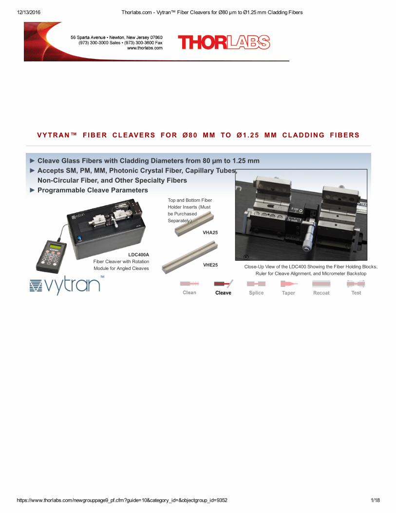
12/13/2016 Thorlabs.com Vytran™ Fiber Cleavers for Ø80 µm to Ø1.25 mm Cladding Fibers https://www.thorlabs.com/newgrouppage9_pf.cfm?guide=10&category_id=&objectgroup_id=9352 1/18 VYTRAN™ FIBER CLEAVERS FOR Ø80 ΜM TO Ø1.25 MM CLADDING FIBERS Cleave Glass Fibers with Cladding Diameters from 80 µm to 1.25 mm Accepts SM, PM, MM, Photonic Crystal Fiber, Capillary Tubes, NonCircular Fiber, and Other Specialty Fibers Programmable Cleave Parameters ► ► ► LDC400A Fiber Cleaver with Rotation Module for Angled Cleaves CloseUp View of the LDC400 Showing the Fiber Holding Blocks, Ruler for Cleave Alignment, and Micrometer Backstop VHA25 VHE25 Top and Bottom Fiber Holder Inserts (Must be Purchased Separately)
Transcript of V Y T R A N ™ F I B E R C L E A V E R S F O R Ø 8 0 Μ M T ... · cleaves (dependent on the...
12/13/2016 Thorlabs.com Vytran™ Fiber Cleavers for Ø80 µm to Ø1.25 mm Cladding Fibers
https://www.thorlabs.com/newgrouppage9_pf.cfm?guide=10&category_id=&objectgroup_id=9352 1/18
VYTRAN™ FIBER CLEAVERS FOR Ø80 ΜM TO Ø1.25 MM CLADDING F IBERS
Cleave Glass Fibers with Cladding Diameters from 80 µm to 1.25 mmAccepts SM, PM, MM, Photonic Crystal Fiber, Capillary Tubes,NonCircular Fiber, and Other Specialty FibersProgrammable Cleave Parameters
LDC400AFiber Cleaver with RotationModule for Angled Cleaves CloseUp View of the LDC400 Showing the Fiber Holding Blocks,
Ruler for Cleave Alignment, and Micrometer Backstop
VHA25
VHE25
Top and Bottom FiberHolder Inserts (Mustbe PurchasedSeparately)
ayang
Text Box
LDC400A - FEB 27, 2017 Item # LDC400A was discontinued on FEB 27, 2017. For informational purposes, this is a copy of the website content at that time and is valid only for the stated product.
tcampbell
Typewritten Text
12/13/2016 Thorlabs.com Vytran™ Fiber Cleavers for Ø80 µm to Ø1.25 mm Cladding Fibers
https://www.thorlabs.com/newgrouppage9_pf.cfm?guide=10&category_id=&objectgroup_id=9352 2/18
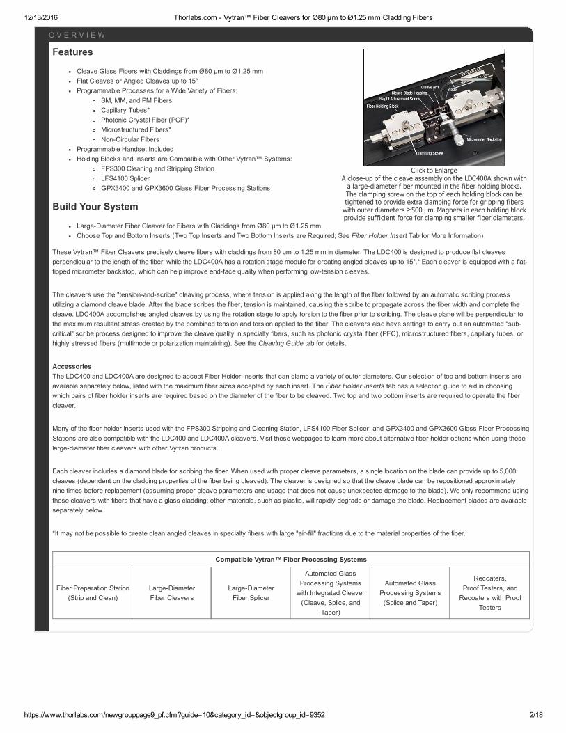
Click to EnlargeA closeup of the cleave assembly on the LDC400A shown witha largediameter fiber mounted in the fiber holding blocks.The clamping screw on the top of each holding block can betightened to provide extra clamping force for gripping fiberswith outer diameters ≥500 µm. Magnets in each holding blockprovide sufficient force for clamping smaller fiber diameters.
Features
Cleave Glass Fibers with Claddings from Ø80 µm to Ø1.25 mmFlat Cleaves or Angled Cleaves up to 15°Programmable Processes for a Wide Variety of Fibers:
SM, MM, and PM FibersCapillary Tubes*Photonic Crystal Fiber (PCF)*Microstructured Fibers*NonCircular Fibers
Programmable Handset IncludedHolding Blocks and Inserts are Compatible with Other Vytran™ Systems:
FPS300 Cleaning and Stripping StationLFS4100 SplicerGPX3400 and GPX3600 Glass Fiber Processing Stations
Build Your System
LargeDiameter Fiber Cleaver for Fibers with Claddings from Ø80 µm to Ø1.25 mmChoose Top and Bottom Inserts (Two Top Inserts and Two Bottom Inserts are Required; See Fiber Holder Insert Tab for More Information)
These Vytran™ Fiber Cleavers precisely cleave fibers with claddings from 80 µm to 1.25 mm in diameter. The LDC400 is designed to produce flat cleavesperpendicular to the length of the fiber, while the LDC400A has a rotation stage module for creating angled cleaves up to 15°.* Each cleaver is equipped with a flattipped micrometer backstop, which can help improve endface quality when performing lowtension cleaves.
The cleavers use the "tensionandscribe" cleaving process, where tension is applied along the length of the fiber followed by an automatic scribing processutilizing a diamond cleave blade. After the blade scribes the fiber, tension is maintained, causing the scribe to propagate across the fiber width and complete thecleave. LDC400A accomplishes angled cleaves by using the rotation stage to apply torsion to the fiber prior to scribing. The cleave plane will be perpendicular tothe maximum resultant stress created by the combined tension and torsion applied to the fiber. The cleavers also have settings to carry out an automated "subcritical" scribe process designed to improve the cleave quality in specialty fibers, such as photonic crystal fiber (PFC), microstructured fibers, capillary tubes, orhighly stressed fibers (multimode or polarization maintaining). See the Cleaving Guide tab for details.
AccessoriesThe LDC400 and LDC400A are designed to accept Fiber Holder Inserts that can clamp a variety of outer diameters. Our selection of top and bottom inserts areavailable separately below, listed with the maximum fiber sizes accepted by each insert. The Fiber Holder Inserts tab has a selection guide to aid in choosingwhich pairs of fiber holder inserts are required based on the diameter of the fiber to be cleaved. Two top and two bottom inserts are required to operate the fibercleaver.
Many of the fiber holder inserts used with the FPS300 Stripping and Cleaning Station, LFS4100 Fiber Splicer, and GPX3400 and GPX3600 Glass Fiber ProcessingStations are also compatible with the LDC400 and LDC400A cleavers. Visit these webpages to learn more about alternative fiber holder options when using theselargediameter fiber cleavers with other Vytran products.
Each cleaver includes a diamond blade for scribing the fiber. When used with proper cleave parameters, a single location on the blade can provide up to 5,000cleaves (dependent on the cladding properties of the fiber being cleaved). The cleaver is designed so that the cleave blade can be repositioned approximatelynine times before replacement (assuming proper cleave parameters and usage that does not cause unexpected damage to the blade). We only recommend usingthese cleavers with fibers that have a glass cladding; other materials, such as plastic, will rapidly degrade or damage the blade. Replacement blades are availableseparately below.
*It may not be possible to create clean angled cleaves in specialty fibers with large "airfill" fractions due to the material properties of the fiber.
Compatible Vytran™ Fiber Processing Systems
Fiber Preparation Station(Strip and Clean)
LargeDiameterFiber Cleavers
LargeDiameterFiber Splicer
Automated GlassProcessing Systemswith Integrated Cleaver(Cleave, Splice, and
Taper)
Automated GlassProcessing Systems(Splice and Taper)
Recoaters,Proof Testers, andRecoaters with Proof
Testers
O V E R V I E W
12/13/2016 Thorlabs.com Vytran™ Fiber Cleavers for Ø80 µm to Ø1.25 mm Cladding Fibers
https://www.thorlabs.com/newgrouppage9_pf.cfm?guide=10&category_id=&objectgroup_id=9352 3/18
S P E C S
12/13/2016 Thorlabs.com Vytran™ Fiber Cleavers for Ø80 µm to Ø1.25 mm Cladding Fibers
https://www.thorlabs.com/newgrouppage9_pf.cfm?guide=10&category_id=&objectgroup_id=9352 4/18
Programmable Handset Parameter Limits
Parameter Default Minimum Maximum
Fiber DiameterFiber SizeDependent
10 µm 1500 µm
Cleave TensionaFiber SizeDependent
1 g 6500 g
PreCleave AdvanceFiber SizeDependent
200 Steps 400 Steps
Set FHB Offset 0 mm 0 mm 47 mm
Tension Velocity 60 Steps/s 4 Steps/s 200 Steps/s
Rotation Angle (LDC400A Only) 0° 0° 180°
Cleave Peck Cycles 60 10 250
Cleave Forward Steps 81 40 400
Cleave Back Steps 80 39 399
Scribe Delay 250 ms 1 ms 5000 ms
Set Blade OffsetUnit Specific
Value100 Steps 2500 Steps
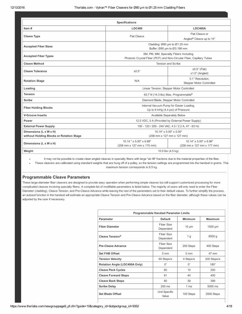
Specifications
Item # LDC400 LDC400A
Cleave Type Flat CleaveFlat Cleave or
Angleda Cleave up to 15°
Accepted Fiber SizesCladding: Ø80 µm to Ø1.25 mmBuffer: Ø80 µm to Ø3.198 mm
Accepted Fiber TypesSM, PM, MM, Specialty Fibers Including
Photonic Crystal Fiber (PCF) and NonCircular Fiber, Capillary Tubes
Cleave Method Tension and Scribe
Cleave Tolerance ±0.5°±0.5° (Flat)
±1.0° (Angled)
Rotation Stage N/A0.1° Resolution,
Stepper Motor Controlled
Loading Linear Tension, Stepper Motor Controlled
Tension 63.7 N (14.3 lbs) Max, Programmableb
Scribe Diamond Blade, Stepper Motor Controlled
Fiber Holding BlocksInternal Vacuum Pump for Easier Loading,
Up to 9 inHg (4.4 psi) of Pressure
VGroove Inserts Available Separately Below
Power 12.5 VDC, 5 A (Provided by External Power Supply)
External Power Supply 100 120 / 200 240 VAC, 4.5 / 2.2 A, 47 63 Hz
Dimensions (L x W x H)without Holding Blocks or Rotation Stage
10.14" x 5.00" x 5.00"(258 mm x 127 mm x 127 mm)
Dimensions (L x W x H)10.14 " x 5.00" x 6.88"
(258 mm x 127 mm x 175 mm)10.14" x 5.00" x 6.96"
(258 mm x 127 mm x 177 mm)
Weight 10.0 lbs (4.5 kg)
It may not be possible to create clean angled cleaves in specialty fibers with large "airfill" fractions due to the material properties of the fiber.These cleavers are calibrated using standard weights that are hung off of a pulley, so the tension settings are programmed into the handset in grams. This
maximum tension corresponds to 6.5 kg.
Programmable Cleave ParametersThese largediameter fiber cleavers are designed to provide easy operation when performing simple cleaves but still support customized processing for morecomplicated cleaves involving specialty fibers. A complete list of modifiable parameters is listed below. The majority of users will only need to enter the FiberDiameter (cladding), Cleave Tension, and PreCleave Advance while leaving the rest of the parameters set to their default values. To further simplify the process,an autoset function in the handset will estimate an appropriate Cleave Tension and PreCleave Advance based on the fiber diameter, although these values can beadjusted by the user if necessary.
12/13/2016 Thorlabs.com Vytran™ Fiber Cleavers for Ø80 µm to Ø1.25 mm Cladding Fibers
https://www.thorlabs.com/newgrouppage9_pf.cfm?guide=10&category_id=&objectgroup_id=9352 5/18
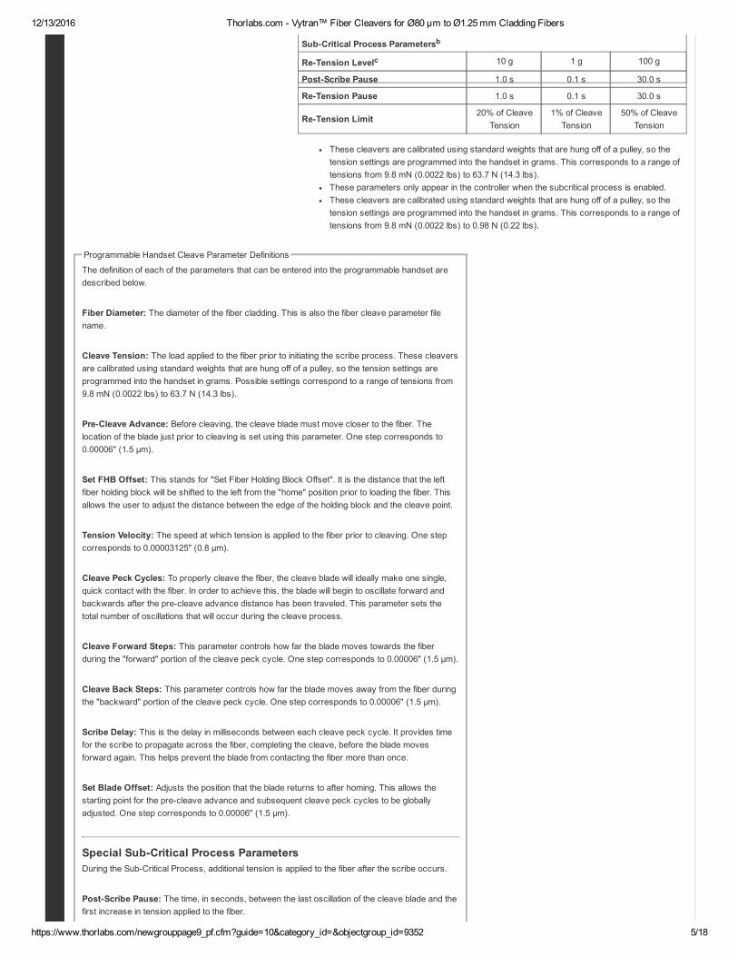
SubCritical Process Parametersb
ReTension Levelc 10 g 1 g 100 g
PostScribe Pause 1.0 s 0.1 s 30.0 s
ReTension Pause 1.0 s 0.1 s 30.0 s
ReTension Limit20% of Cleave
Tension1% of Cleave
Tension50% of Cleave
Tension
These cleavers are calibrated using standard weights that are hung off of a pulley, so thetension settings are programmed into the handset in grams. This corresponds to a range oftensions from 9.8 mN (0.0022 lbs) to 63.7 N (14.3 lbs).These parameters only appear in the controller when the subcritical process is enabled.These cleavers are calibrated using standard weights that are hung off of a pulley, so thetension settings are programmed into the handset in grams. This corresponds to a range oftensions from 9.8 mN (0.0022 lbs) to 0.98 N (0.22 lbs).
Programmable Handset Cleave Parameter Definitions
The definition of each of the parameters that can be entered into the programmable handset aredescribed below.
Fiber Diameter: The diameter of the fiber cladding. This is also the fiber cleave parameter filename.
Cleave Tension: The load applied to the fiber prior to initiating the scribe process. These cleaversare calibrated using standard weights that are hung off of a pulley, so the tension settings areprogrammed into the handset in grams. Possible settings correspond to a range of tensions from9.8 mN (0.0022 lbs) to 63.7 N (14.3 lbs).
PreCleave Advance: Before cleaving, the cleave blade must move closer to the fiber. Thelocation of the blade just prior to cleaving is set using this parameter. One step corresponds to0.00006" (1.5 µm).
Set FHB Offset: This stands for "Set Fiber Holding Block Offset". It is the distance that the leftfiber holding block will be shifted to the left from the "home" position prior to loading the fiber. Thisallows the user to adjust the distance between the edge of the holding block and the cleave point.
Tension Velocity: The speed at which tension is applied to the fiber prior to cleaving. One stepcorresponds to 0.00003125" (0.8 µm).
Cleave Peck Cycles: To properly cleave the fiber, the cleave blade will ideally make one single,quick contact with the fiber. In order to achieve this, the blade will begin to oscillate forward andbackwards after the precleave advance distance has been traveled. This parameter sets thetotal number of oscillations that will occur during the cleave process.
Cleave Forward Steps: This parameter controls how far the blade moves towards the fiberduring the "forward" portion of the cleave peck cycle. One step corresponds to 0.00006" (1.5 µm).
Cleave Back Steps: This parameter controls how far the blade moves away from the fiber duringthe "backward" portion of the cleave peck cycle. One step corresponds to 0.00006" (1.5 µm).
Scribe Delay: This is the delay in milliseconds between each cleave peck cycle. It provides timefor the scribe to propagate across the fiber, completing the cleave, before the blade movesforward again. This helps prevent the blade from contacting the fiber more than once.
Set Blade Offset: Adjusts the position that the blade returns to after homing. This allows thestarting point for the precleave advance and subsequent cleave peck cycles to be globallyadjusted. One step corresponds to 0.00006" (1.5 µm).
Special SubCritical Process ParametersDuring the SubCritical Process, additional tension is applied to the fiber after the scribe occurs.
PostScribe Pause: The time, in seconds, between the last oscillation of the cleave blade and thefirst increase in tension applied to the fiber.
12/13/2016 Thorlabs.com Vytran™ Fiber Cleavers for Ø80 µm to Ø1.25 mm Cladding Fibers
https://www.thorlabs.com/newgrouppage9_pf.cfm?guide=10&category_id=&objectgroup_id=9352 6/18
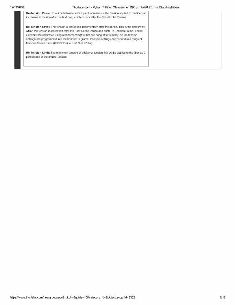
ReTension Pause: The time between subsequent increases in the tension applied to the fiber (allincreases in tension after the first one, which occurs after the PostScribe Pause).
ReTension Level: The tension is increased incrementally after the scribe. This is the amount bywhich the tension is increased after the PostScribe Pause and each ReTension Pause. Thesecleavers are calibrated using standards weights that are hung off of a pulley, so the tensionsettings are programmed into the handset in grams. Possible settings correspond to a range oftensions from 9.8 mN (0.0022 lbs) to 0.98 N (0.22 lbs).
ReTension Limit: The maximum amount of additional tension that will be applied to the fiber as apercentage of the original tension.
12/13/2016 Thorlabs.com Vytran™ Fiber Cleavers for Ø80 µm to Ø1.25 mm Cladding Fibers
https://www.thorlabs.com/newgrouppage9_pf.cfm?guide=10&category_id=&objectgroup_id=9352 7/18
F I B E R H O L D E R I N S E R T S
12/13/2016 Thorlabs.com Vytran™ Fiber Cleavers for Ø80 µm to Ø1.25 mm Cladding Fibers
https://www.thorlabs.com/newgrouppage9_pf.cfm?guide=10&category_id=&objectgroup_id=9352 8/18
Each Vgroove can accommodate a range of fiber sizes.
Legend
Best Fit
Second Best Fit: Try these options if the best fit does not incorporate your fiber sizes.
Third Best Fit: Try these options if the other two categories do not incorporate your fibersizes.
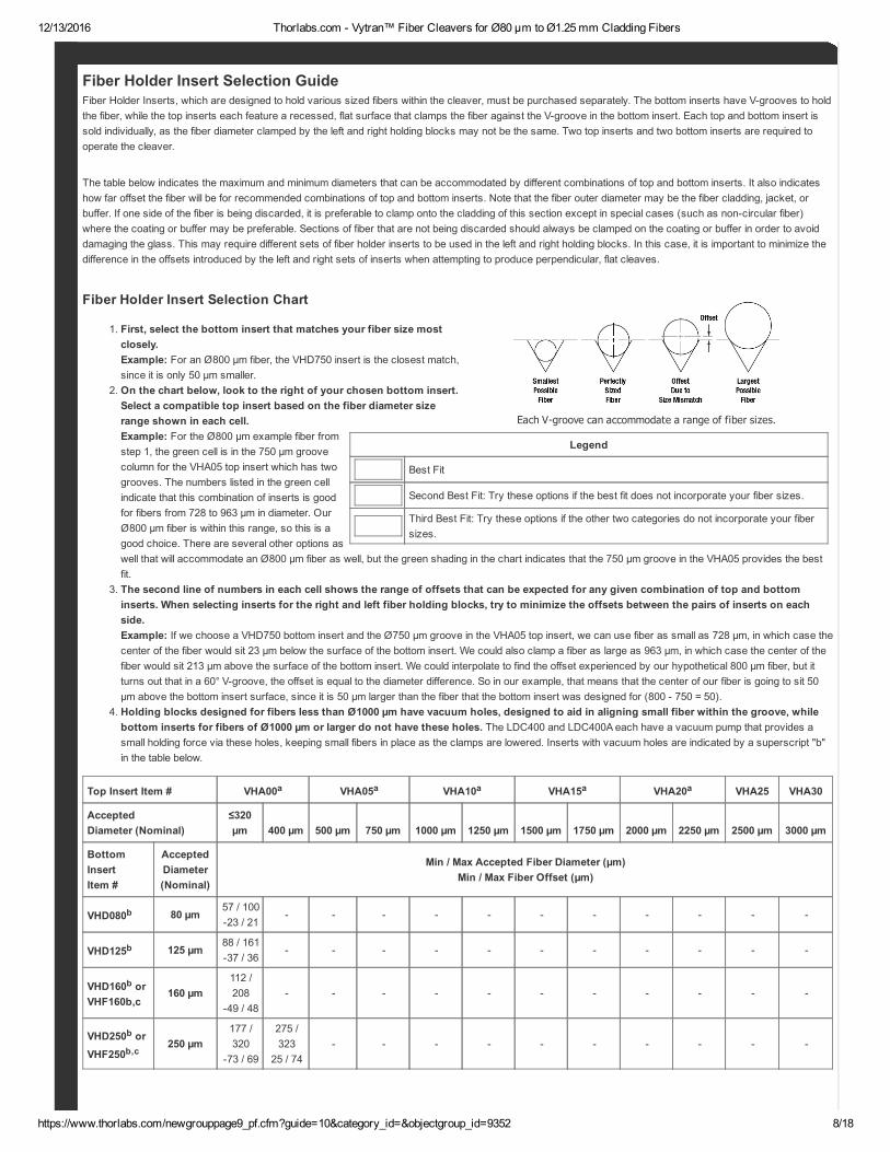
Fiber Holder Insert Selection GuideFiber Holder Inserts, which are designed to hold various sized fibers within the cleaver, must be purchased separately. The bottom inserts have Vgrooves to holdthe fiber, while the top inserts each feature a recessed, flat surface that clamps the fiber against the Vgroove in the bottom insert. Each top and bottom insert issold individually, as the fiber diameter clamped by the left and right holding blocks may not be the same. Two top inserts and two bottom inserts are required tooperate the cleaver.
The table below indicates the maximum and minimum diameters that can be accommodated by different combinations of top and bottom inserts. It also indicateshow far offset the fiber will be for recommended combinations of top and bottom inserts. Note that the fiber outer diameter may be the fiber cladding, jacket, orbuffer. If one side of the fiber is being discarded, it is preferable to clamp onto the cladding of this section except in special cases (such as noncircular fiber)where the coating or buffer may be preferable. Sections of fiber that are not being discarded should always be clamped on the coating or buffer in order to avoiddamaging the glass. This may require different sets of fiber holder inserts to be used in the left and right holding blocks. In this case, it is important to minimize thedifference in the offsets introduced by the left and right sets of inserts when attempting to produce perpendicular, flat cleaves.
Fiber Holder Insert Selection Chart
1. First, select the bottom insert that matches your fiber size mostclosely.Example: For an Ø800 µm fiber, the VHD750 insert is the closest match,since it is only 50 µm smaller.
2. On the chart below, look to the right of your chosen bottom insert.Select a compatible top insert based on the fiber diameter sizerange shown in each cell.Example: For the Ø800 µm example fiber fromstep 1, the green cell is in the 750 µm groovecolumn for the VHA05 top insert which has twogrooves. The numbers listed in the green cellindicate that this combination of inserts is goodfor fibers from 728 to 963 µm in diameter. OurØ800 µm fiber is within this range, so this is agood choice. There are several other options aswell that will accommodate an Ø800 µm fiber as well, but the green shading in the chart indicates that the 750 µm groove in the VHA05 provides the bestfit.
3. The second line of numbers in each cell shows the range of offsets that can be expected for any given combination of top and bottominserts. When selecting inserts for the right and left fiber holding blocks, try to minimize the offsets between the pairs of inserts on eachside.Example: If we choose a VHD750 bottom insert and the Ø750 µm groove in the VHA05 top insert, we can use fiber as small as 728 µm, in which case thecenter of the fiber would sit 23 µm below the surface of the bottom insert. We could also clamp a fiber as large as 963 µm, in which case the center of thefiber would sit 213 µm above the surface of the bottom insert. We could interpolate to find the offset experienced by our hypothetical 800 µm fiber, but itturns out that in a 60° Vgroove, the offset is equal to the diameter difference. So in our example, that means that the center of our fiber is going to sit 50µm above the bottom insert surface, since it is 50 µm larger than the fiber that the bottom insert was designed for (800 750 = 50).
4. Holding blocks designed for fibers less than Ø1000 µm have vacuum holes, designed to aid in aligning small fiber within the groove, whilebottom inserts for fibers of Ø1000 µm or larger do not have these holes. The LDC400 and LDC400A each have a vacuum pump that provides asmall holding force via these holes, keeping small fibers in place as the clamps are lowered. Inserts with vacuum holes are indicated by a superscript "b"in the table below.
Top Insert Item # VHA00a VHA05a VHA10a VHA15a VHA20a VHA25 VHA30
AcceptedDiameter (Nominal)
≤320µm 400 µm 500 µm 750 µm 1000 µm 1250 µm 1500 µm 1750 µm 2000 µm 2250 µm 2500 µm 3000 µm
BottomInsertItem #
AcceptedDiameter(Nominal)
Min / Max Accepted Fiber Diameter (µm)Min / Max Fiber Offset (µm)
VHD080b 80 µm57 / 10023 / 21
VHD125b 125 µm88 / 16137 / 36
VHD160b orVHF160b,c
160 µm112 /208
49 / 48
VHD250b orVHF250b,c
250 µm177 /320
73 / 69
275 /323
25 / 74
12/13/2016 Thorlabs.com Vytran™ Fiber Cleavers for Ø80 µm to Ø1.25 mm Cladding Fibers
https://www.thorlabs.com/newgrouppage9_pf.cfm?guide=10&category_id=&objectgroup_id=9352 9/18
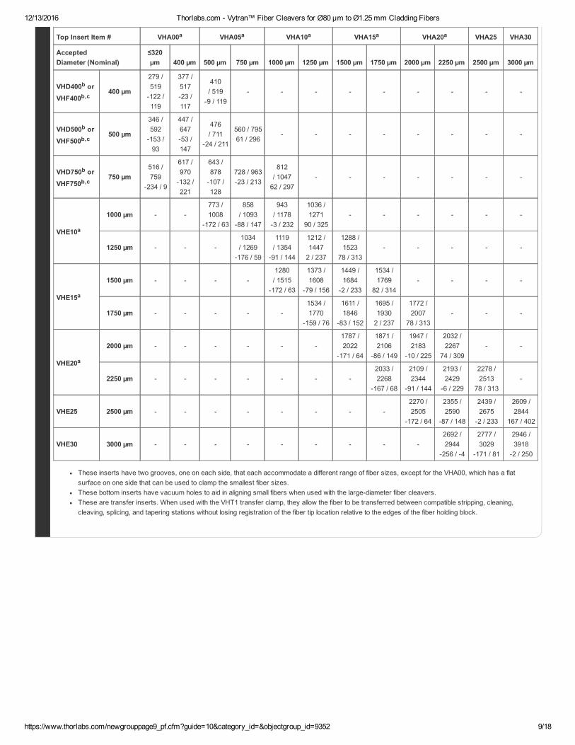
Top Insert Item # VHA00a VHA05a VHA10a VHA15a VHA20a VHA25 VHA30
AcceptedDiameter (Nominal)
≤320µm 400 µm 500 µm 750 µm 1000 µm 1250 µm 1500 µm 1750 µm 2000 µm 2250 µm 2500 µm 3000 µm
VHD400b orVHF400b,c
400 µm
279 /519122 /119
377 /51723 /117
410/ 5199 / 119
VHD500b orVHF500b,c
500 µm
346 /592153 /93
447 /64753 /147
476/ 711
24 / 211
560 / 79561 / 296
VHD750b orVHF750b,c
750 µm516 /759
234 / 9
617 /970132 /221
643 /878107 /128
728 / 96323 / 213
812/ 104762 / 297
VHE10a
1000 µm 773 /1008
172 / 63
858/ 1093
88 / 147
943/ 11783 / 232
1036 /1271
90 / 325
1250 µm 1034/ 1269
176 / 59
1119/ 1354
91 / 144
1212 /14472 / 237
1288 /1523
78 / 313
VHE15a
1500 µm 1280/ 1515
172 / 63
1373 /1608
79 / 156
1449 /1684
2 / 233
1534 /1769
82 / 314
1750 µm 1534 /1770
159 / 76
1611 /1846
83 / 152
1695 /19302 / 237
1772 /2007
78 / 313
VHE20a
2000 µm 1787 /2022
171 / 64
1871 /2106
86 / 149
1947 /2183
10 / 225
2032 /2267
74 / 309
2250 µm 2033 /2268
167 / 68
2109 /2344
91 / 144
2193 /2429
6 / 229
2278 /2513
78 / 313
VHE25 2500 µm 2270 /2505
172 / 64
2355 /2590
87 / 148
2439 /2675
2 / 233
2609 /2844
167 / 402
VHE30 3000 µm 2692 /2944
256 / 4
2777 /3029
171 / 81
2946 /3918
2 / 250
These inserts have two grooves, one on each side, that each accommodate a different range of fiber sizes, except for the VHA00, which has a flatsurface on one side that can be used to clamp the smallest fiber sizes.These bottom inserts have vacuum holes to aid in aligning small fibers when used with the largediameter fiber cleavers.These are transfer inserts. When used with the VHT1 transfer clamp, they allow the fiber to be transferred between compatible stripping, cleaning,cleaving, splicing, and tapering stations without losing registration of the fiber tip location relative to the edges of the fiber holding block.
12/13/2016 Thorlabs.com Vytran™ Fiber Cleavers for Ø80 µm to Ø1.25 mm Cladding Fibers
https://www.thorlabs.com/newgrouppage9_pf.cfm?guide=10&category_id=&objectgroup_id=9352 10/18
C L E A V I N G G U I D E
12/13/2016 Thorlabs.com Vytran™ Fiber Cleavers for Ø80 µm to Ø1.25 mm Cladding Fibers
https://www.thorlabs.com/newgrouppage9_pf.cfm?guide=10&category_id=&objectgroup_id=9352 11/18
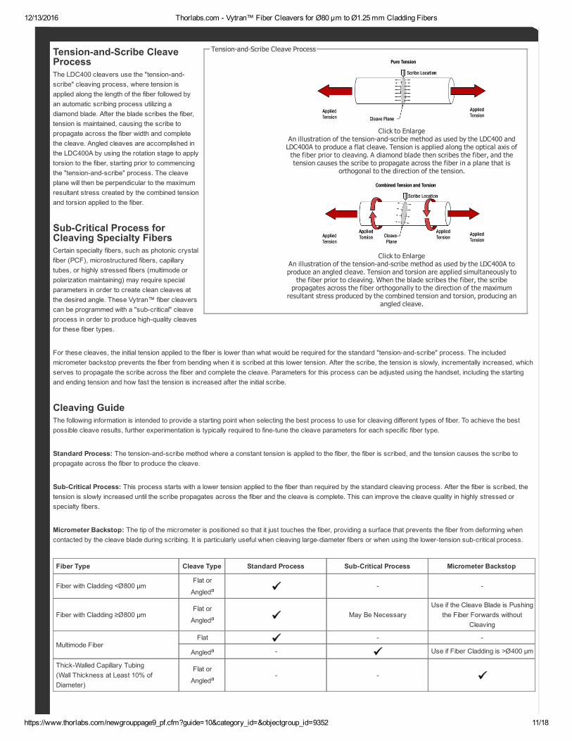
Click to EnlargeAn illustration of the tensionandscribe method as used by the LDC400 andLDC400A to produce a flat cleave. Tension is applied along the optical axis ofthe fiber prior to cleaving. A diamond blade then scribes the fiber, and thetension causes the scribe to propagate across the fiber in a plane that is
orthogonal to the direction of the tension.
Click to EnlargeAn illustration of the tensionandscribe method as used by the LDC400A toproduce an angled cleave. Tension and torsion are applied simultaneously tothe fiber prior to cleaving. When the blade scribes the fiber, the scribepropagates across the fiber orthogonally to the direction of the maximumresultant stress produced by the combined tension and torsion, producing an
angled cleave.
TensionandScribe Cleave ProcessTensionandScribe CleaveProcessThe LDC400 cleavers use the "tensionandscribe" cleaving process, where tension isapplied along the length of the fiber followed byan automatic scribing process utilizing adiamond blade. After the blade scribes the fiber,tension is maintained, causing the scribe topropagate across the fiber width and completethe cleave. Angled cleaves are accomplished inthe LDC400A by using the rotation stage to applytorsion to the fiber, starting prior to commencingthe "tensionandscribe" process. The cleaveplane will then be perpendicular to the maximumresultant stress created by the combined tensionand torsion applied to the fiber.
SubCritical Process forCleaving Specialty FibersCertain specialty fibers, such as photonic crystalfiber (PCF), microstructured fibers, capillarytubes, or highly stressed fibers (multimode orpolarization maintaining) may require specialparameters in order to create clean cleaves atthe desired angle. These Vytran™ fiber cleaverscan be programmed with a "subcritical" cleaveprocess in order to produce highquality cleavesfor these fiber types.
For these cleaves, the initial tension applied to the fiber is lower than what would be required for the standard "tensionandscribe" process. The includedmicrometer backstop prevents the fiber from bending when it is scribed at this lower tension. After the scribe, the tension is slowly, incrementally increased, whichserves to propagate the scribe across the fiber and complete the cleave. Parameters for this process can be adjusted using the handset, including the startingand ending tension and how fast the tension is increased after the initial scribe.
Cleaving GuideThe following information is intended to provide a starting point when selecting the best process to use for cleaving different types of fiber. To achieve the bestpossible cleave results, further experimentation is typically required to finetune the cleave parameters for each specific fiber type.
Standard Process: The tensionandscribe method where a constant tension is applied to the fiber, the fiber is scribed, and the tension causes the scribe topropagate across the fiber to produce the cleave.
SubCritical Process: This process starts with a lower tension applied to the fiber than required by the standard cleaving process. After the fiber is scribed, thetension is slowly increased until the scribe propagates across the fiber and the cleave is complete. This can improve the cleave quality in highly stressed orspecialty fibers.
Micrometer Backstop: The tip of the micrometer is positioned so that it just touches the fiber, providing a surface that prevents the fiber from deforming whencontacted by the cleave blade during scribing. It is particularly useful when cleaving largediameter fibers or when using the lowertension subcritical process.
Fiber Type Cleave Type Standard Process SubCritical Process Micrometer Backstop
Fiber with Cladding <Ø800 µmFlat or
Angleda
Fiber with Cladding ≥Ø800 µmFlat or
AngledaMay Be Necessary
Use if the Cleave Blade is Pushingthe Fiber Forwards without
Cleaving
Multimode FiberFlat
Angleda Use if Fiber Cladding is >Ø400 µm
ThickWalled Capillary Tubing(Wall Thickness at Least 10% ofDiameter)
Flat or
Angleda
12/13/2016 Thorlabs.com Vytran™ Fiber Cleavers for Ø80 µm to Ø1.25 mm Cladding Fibers
https://www.thorlabs.com/newgrouppage9_pf.cfm?guide=10&category_id=&objectgroup_id=9352 12/18
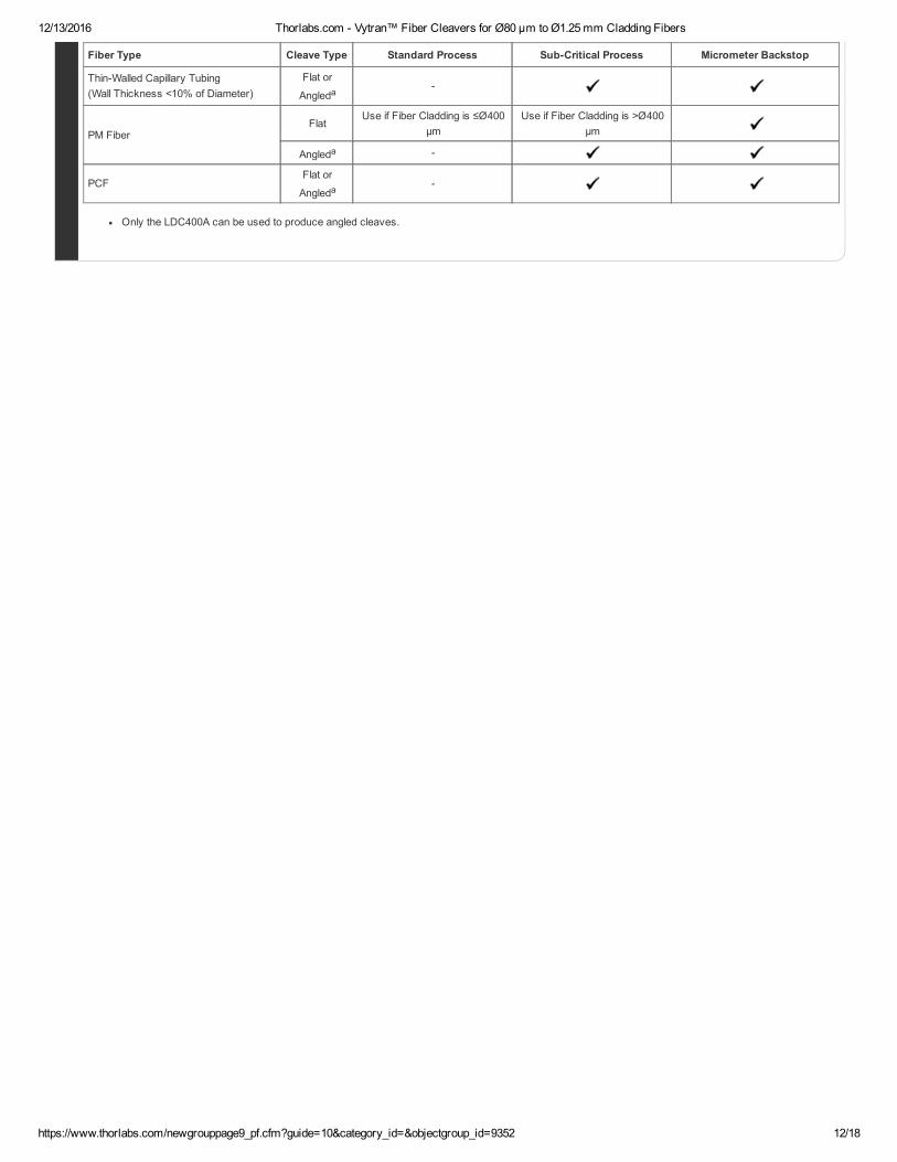
Fiber Type Cleave Type Standard Process SubCritical Process Micrometer Backstop
ThinWalled Capillary Tubing(Wall Thickness <10% of Diameter)
Flat or
Angleda
PM FiberFlat
Use if Fiber Cladding is ≤Ø400µm
Use if Fiber Cladding is >Ø400µm
Angleda
PCFFlat or
Angleda
Only the LDC400A can be used to produce angled cleaves.
12/13/2016 Thorlabs.com Vytran™ Fiber Cleavers for Ø80 µm to Ø1.25 mm Cladding Fibers
https://www.thorlabs.com/newgrouppage9_pf.cfm?guide=10&category_id=&objectgroup_id=9352 13/18
Thorlabs Vytran EuropeExeter, United Kingdom2 Kew CourtExeter EX2 5AZUnited Kingdom
Appointment Scheduling and Customer Support
Phone: +44 (0) 1392445777Email: [email protected]
Click to Enlarge
Thorlabs ChinaShanghai, ChinaRoom A101, No.100, Lane 2891, South Qilianshan RoadShanghai 200331China
Appointment Scheduling and Customer Support
Phone: +86 (0) 2160561122Email: techsupport[email protected]
Click to Enlarge
Thorlabs Vytran USAMorganville, New Jersey, USA1400 Campus DrMorganville, NJ 07751USA
Appointment Scheduling and Customer Support
Phone: (973) 3003000Email: [email protected]
Click to Enlarge
ProductDemonstrations
Thorlabs has demonstration facilitates for the Vytran™ fiber glass processing systems offered on this page within our Morganville, New Jersey; Exeter,Devonshire; and Shanghai, China offices. We invite you to schedule a visit to see these products in operation and to discuss the various options with afiber processing specialist. Please schedule a demonstration at one of our locations below by contacting technical support. We welcome the opportunityfor personal interaction during your visit!
P R O D U C T D E M O S
12/13/2016 Thorlabs.com Vytran™ Fiber Cleavers for Ø80 µm to Ø1.25 mm Cladding Fibers
https://www.thorlabs.com/newgrouppage9_pf.cfm?guide=10&category_id=&objectgroup_id=9352 14/18
Components
Included
LDC400 or LDC400AHandset Controller12 V Power SupplyLocationSpecific AC Power CordDC Power CordTool Kit with 0.035", 0.050", and 3/32" Allen Keys
Must be Purchased Separately
Fiber Holder Top Inserts (Two Required)Fiber Holder Bottom Inserts (Two Required)
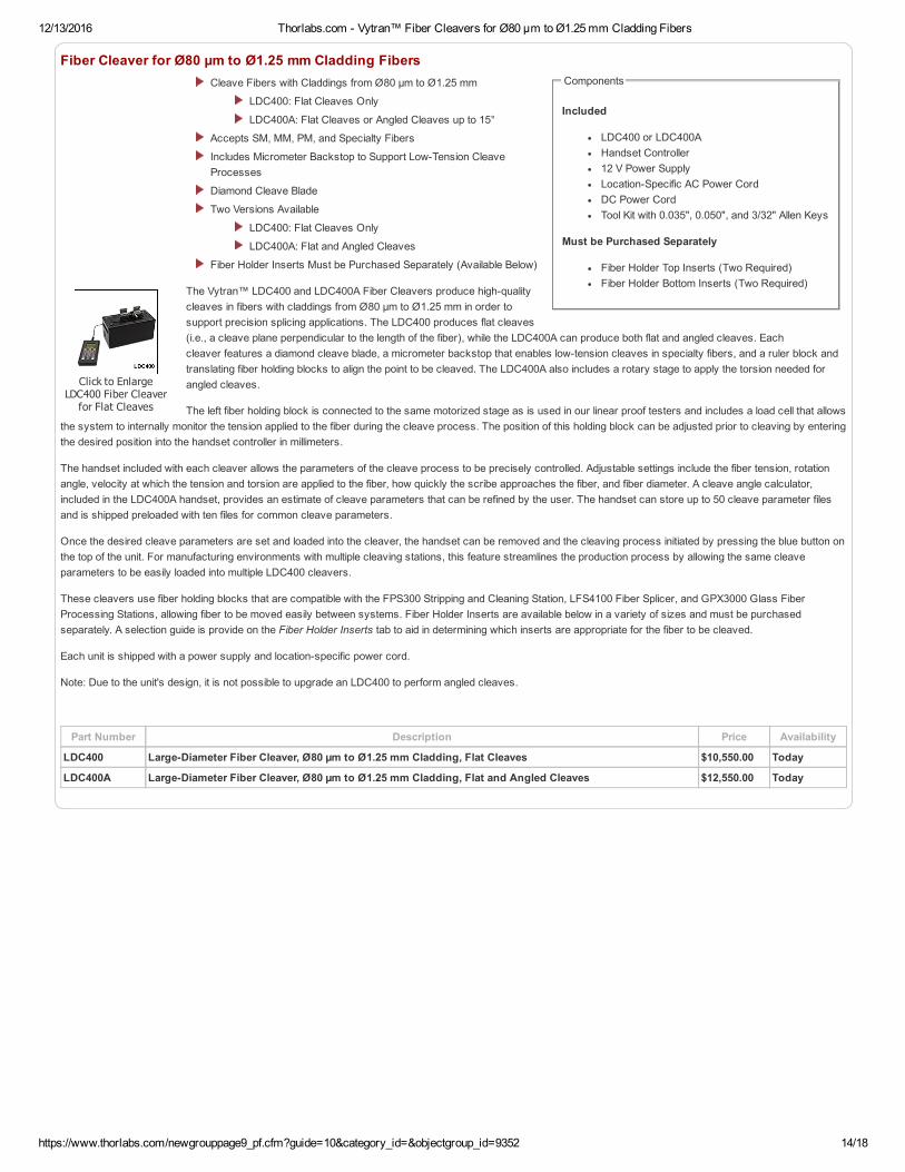
Click to EnlargeLDC400 Fiber Cleaverfor Flat Cleaves
Fiber Cleaver for Ø80 µm to Ø1.25 mm Cladding FibersCleave Fibers with Claddings from Ø80 µm to Ø1.25 mm
LDC400: Flat Cleaves Only
LDC400A: Flat Cleaves or Angled Cleaves up to 15°
Accepts SM, MM, PM, and Specialty Fibers
Includes Micrometer Backstop to Support LowTension CleaveProcesses
Diamond Cleave Blade
Two Versions Available
LDC400: Flat Cleaves Only
LDC400A: Flat and Angled Cleaves
Fiber Holder Inserts Must be Purchased Separately (Available Below)
The Vytran™ LDC400 and LDC400A Fiber Cleavers produce highqualitycleaves in fibers with claddings from Ø80 µm to Ø1.25 mm in order tosupport precision splicing applications. The LDC400 produces flat cleaves(i.e., a cleave plane perpendicular to the length of the fiber), while the LDC400A can produce both flat and angled cleaves. Eachcleaver features a diamond cleave blade, a micrometer backstop that enables lowtension cleaves in specialty fibers, and a ruler block andtranslating fiber holding blocks to align the point to be cleaved. The LDC400A also includes a rotary stage to apply the torsion needed forangled cleaves.
The left fiber holding block is connected to the same motorized stage as is used in our linear proof testers and includes a load cell that allowsthe system to internally monitor the tension applied to the fiber during the cleave process. The position of this holding block can be adjusted prior to cleaving by enteringthe desired position into the handset controller in millimeters.
The handset included with each cleaver allows the parameters of the cleave process to be precisely controlled. Adjustable settings include the fiber tension, rotationangle, velocity at which the tension and torsion are applied to the fiber, how quickly the scribe approaches the fiber, and fiber diameter. A cleave angle calculator,included in the LDC400A handset, provides an estimate of cleave parameters that can be refined by the user. The handset can store up to 50 cleave parameter filesand is shipped preloaded with ten files for common cleave parameters.
Once the desired cleave parameters are set and loaded into the cleaver, the handset can be removed and the cleaving process initiated by pressing the blue button onthe top of the unit. For manufacturing environments with multiple cleaving stations, this feature streamlines the production process by allowing the same cleaveparameters to be easily loaded into multiple LDC400 cleavers.
These cleavers use fiber holding blocks that are compatible with the FPS300 Stripping and Cleaning Station, LFS4100 Fiber Splicer, and GPX3000 Glass FiberProcessing Stations, allowing fiber to be moved easily between systems. Fiber Holder Inserts are available below in a variety of sizes and must be purchasedseparately. A selection guide is provide on the Fiber Holder Inserts tab to aid in determining which inserts are appropriate for the fiber to be cleaved.
Each unit is shipped with a power supply and locationspecific power cord.
Note: Due to the unit's design, it is not possible to upgrade an LDC400 to perform angled cleaves.
Part Number Description Price Availability
LDC400 LargeDiameter Fiber Cleaver, Ø80 µm to Ø1.25 mm Cladding, Flat Cleaves $10,550.00 Today
LDC400A LargeDiameter Fiber Cleaver, Ø80 µm to Ø1.25 mm Cladding, Flat and Angled Cleaves $12,550.00 Today
12/13/2016 Thorlabs.com Vytran™ Fiber Cleavers for Ø80 µm to Ø1.25 mm Cladding Fibers
https://www.thorlabs.com/newgrouppage9_pf.cfm?guide=10&category_id=&objectgroup_id=9352 15/18
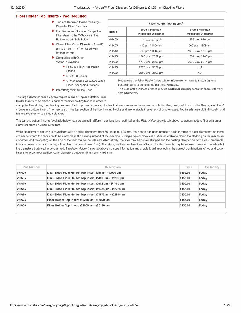
Fiber Holder Top Insertsa
Item #Side 1 Min/Max
Accepted DiameterSide 2 Min/Max
Accepted Diameter
VHA00 57 µm / 759 µmb 275 µm / 970 µm
VHA05 410 µm / 1008 µm 560 µm / 1269 µm
VHA10 812 µm / 1515 µm 1036 µm / 1770 µm
VHA15 1288 µm / 2022 µm 1534 µm / 2268 µm
VHA20 1772 µm / 2505 µm 2032 µm / 2944 µm
VHA25 2278 µm / 3029 µm N/A
VHA30 2609 µm / 3198 µm N/A
Please see the Fiber Holder Insert tab for information on how to match top andbottom inserts to achieve the best cleave quality.This side of the VHA00 is flat to provide additional clamping force for fibers with verysmall diameters.
Fiber Holder Top Inserts Two RequiredTwo are Required to use the LargeDiameter Fiber Cleavers
Flat, Recessed Surface Clamps theFiber Against the VGroove in theBottom Insert (Sold Below)
Clamp Fiber Outer Diameters from 57µm to 3.198 mm When Used withBottom Inserts
Compatible with OtherVytran™ Systems
FPS300 Fiber PreparationStation
LFS4100 Splicer
GPX3400 and GPX3600 GlassFiber Processing Stations
Interchangeable by the User
The largediameter fiber cleavers require a pair of Top and Bottom FiberHolder Inserts to be placed in each of the fiber holding blocks in order toclamp the fiber during the cleaving process. Each top insert consists of a bar that has a recessed area on one or both sides, designed to clamp the fiber against the Vgroove in a bottom insert. The inserts sit in the top section of the fiber holding blocks and are available in a variety of groove sizes. Top inserts are sold individually, andtwo are required to use these cleavers.
The top and bottom inserts (available below) can be paired in different combinations, outlined on the Fiber Holder Inserts tab above, to accommodate fiber with outerdiameters from 57 µm to 3.198 mm.
While the cleavers can only cleave fibers with cladding diameters from 80 µm up to 1.25 mm, the inserts can accommodate a wider range of outer diameters, as thereare cases where the fiber should be clamped on the coating instead of the cladding. During a typical cleave, it is often desirable to clamp the cladding on the side to bediscarded and the coating on the side of the fiber that will be retained. Alternatively, the fiber may be center stripped and the coating clamped on both sides (preferablein some cases, such as creating a firm clamp on noncircular fiber). Therefore, multiple combinations of top and bottom inserts may be required to accommodate all ofthe diameters that need to be clamped. The Fiber Holder Insert tab above includes information and a table to aid in selecting the correct combinations of top and bottominserts to accommodate fiber outer diameters between 57 µm and 3.198 mm.
Part Number Description Price Availability
VHA00 DualSided Fiber Holder Top Insert, Ø57 µm Ø970 µm $155.00 Today
VHA05 DualSided Fiber Holder Top Insert, Ø410 µm Ø1269 µm $155.00 Today
VHA10 DualSided Fiber Holder Top Insert, Ø812 µm Ø1770 µm $155.00 Today
VHA15 DualSided Fiber Holder Top Insert, Ø1288 µm Ø2268 µm $155.00 Today
VHA20 DualSided Fiber Holder Top Insert, Ø1772 µm Ø2944 µm $155.00 Today
VHA25 Fiber Holder Top Insert, Ø2278 µm Ø3029 µm $155.00 Today
VHA30 Fiber Holder Top Insert, Ø2609 µm Ø3198 µm $155.00 Today

12/13/2016 Thorlabs.com Vytran™ Fiber Cleavers for Ø80 µm to Ø1.25 mm Cladding Fibers
https://www.thorlabs.com/newgrouppage9_pf.cfm?guide=10&category_id=&objectgroup_id=9352 16/18
Fiber Holder Bottom Insertsa
Item #TransferInsert
Side 1 Min/MaxAccepted Diameter
Side 2 Min/MaxAccepted Diameter
VacuumHoles
VHD080 No 57 µm / 100 µm N/A Yes
VHD125 No 88 µm / 161 µm N/A Yes
VHD160 No112 µm / 208 µm N/A Yes
VHF160 Yesb
VHD250 No177 µm / 320 µm N/A Yes
VHF250 Yesb
VHD400 No279 µm / 519 µm N/A Yes
VHF400 Yesb
VHD500 No346 µm / 795 µm N/A Yes
VHF500 Yesb
VHD750 No516 µm / 1047 µm N/A Yes
VHF750 Yesb
VHE10 No 773 µm / 1271 µm 1034 µm / 1523 µm No
VHE15 No 1280 µm / 1769 µm 1534 µm / 2007 µm No
VHE20 No 1787 µm / 2267 µm 2033 µm / 2513 µm No
VHE25 No 2270 µm / 2844 µm N/A No
VHE30 No 2692 µm / 3198 µm N/A No
Please see the Fiber Holder Insert tab for information on how to match top andbottom inserts to achieve the best cleave quality.If using these cleavers with other compatible Vytran™ systems, a transfer insertmay be used in place of the standard bottom insert. Combined with the VHT1transfer clamp, the transfer inserts allow the fiber to be moved between compatibleVytran™ stations while maintaining coarse alignment.
Fiber Holder Bottom Inserts Two RequiredTwo are Required to Use the LDC400or LDC400A
VGroove Fiber Holder InsertBottom Inserts
Clamp Fiber Outer Diameters from 57µm to 3.198 mm when Used withTop Inserts (Available Above)
VHD and VHF Series of InsertsHave Holes for Vacuum Suction to Aidin Positioning Small Fibers when Usedin the LDC400 or LDC400A (See theTable to the Right)
Use a Transfer Insert with the VHT1Transfer Clamp to Aid in Transferring aFiber with a Coating ≤Ø1.047 mmbetween Compatible Vytran™ Systems
FPS300 Fiber PreparationStation
LFS4100 Splicer
GPX3400 and GPX3600 GlassFiber Processing Stations
Interchangeable by the User
The largediameter fiber cleavers require a pair of Top and Bottom FiberHolder Inserts to be placed in each of the fiber holding blocks in order toclamp the fiber during the cleaving process. Each bottom insert has aVGroove on one or both sides that can accommodate a range ofdiameters (as indicated in the table to the right).
Three types of bottom inserts are available for these largediameterfiber cleavers. Standard bottom inserts for fiber with an outer diameter<Ø1.047 mm have vacuum holes to help position the fiber in the groovewhen loading the cleaver. For certain fiber diameters, we also offertransfer inserts (Item #s beginning with VHF) designed to work with theVHT1 transfer clamps (available below) that aid in moving the fiberbetween compatible Vytran™ stations while maintaining coarse alignment. The VHE series of fiber holder bottom inserts have a VGroove on one (VHE25 and VHE30)or both sides (VHE10, VHE15, and VHE20) but do not include vacuum holes. The VHF transfer inserts and VHE bottom inserts can both be installed in other,compatible Vytran™ stations, although the VHE bottom inserts cannot be used with the VHT1 transfer clamp.
Bottom inserts are sold individually, and two are required to use the largediameter cleavers. If using the fiber cleaver as a standalone device, the VHD series or VHEseries inserts will be sufficient. If using the cleavers with other compatible Vytran™ systems, the bottom insert in the left fiber holding block can be replaced with atransfer insert and VHT1 transfer clamp (available below) for certain fiber sizes, as indicated in the table to the right. Typically, these transfer inserts would only beused in the left fiber holder block, as the right fiber holding block usually clamps the side of the fiber that will be discarded. The right fiber holding block of the LDC400can accept transfer inserts, if desired, while the right fiber holding block of the LDC400A is incompatible with the transfer inserts, due to the presence of the rotationstage.
The top (available above) and bottom fiber holder inserts can be paired in different combinations, outlined on the Fiber Holder Inserts tab above, to accommodate fiberwith outer diameters from 57 µm to 3.918 mm. While the cleavers can only cleave fibers with cladding diameters from 80 µm up to 1.25 mm, the inserts canaccommodate a wider range of outer diameters, as there are cases where the fiber should be clamped on the coating instead of the cladding. During a typical cleave, itis often desirable to clamp the cladding on the side to be discarded and the coating on the side of the fiber that will be retained. Alternatively, the fiber may be centerstripped and the coating clamped on both sides (preferable in some cases, such as creating a firm clamp on noncircular fiber). Therefore, multiple combinations of topand bottom inserts may be required. The Fiber Holder Insert tab above includes information and a table to aid in selecting the correct combinations of top and bottominserts to accommodate fiber outer diameters from 57 µm to 3.198 mm.
Part Number Description Price Availability
VHD080 Fiber Holder Bottom Insert, Ø57 µm Ø100 µm $195.00 Today
VHD125 Fiber Holder Bottom Insert, Ø88 µm Ø161 µm $195.00 Today
VHD160 Fiber Holder Bottom Insert, Ø112 µm Ø208 µm $195.00 Today
VHF160 Fiber Holder Transfer Bottom Insert, Ø112 µm Ø208 µm $290.00 Today
VHD250 Fiber Holder Bottom Insert, Ø177 µm Ø320 µm $195.00 Today
VHF250 Fiber Holder Transfer Bottom Insert, Ø177 µm Ø320 µm $290.00 Today
VHD400 Fiber Holder Bottom Insert, Ø279 µm Ø519 µm $195.00 Today
VHF400 Fiber Holder Transfer Bottom Insert, Ø279 µm Ø519 µm $290.00 Today
12/13/2016 Thorlabs.com Vytran™ Fiber Cleavers for Ø80 µm to Ø1.25 mm Cladding Fibers
https://www.thorlabs.com/newgrouppage9_pf.cfm?guide=10&category_id=&objectgroup_id=9352 17/18
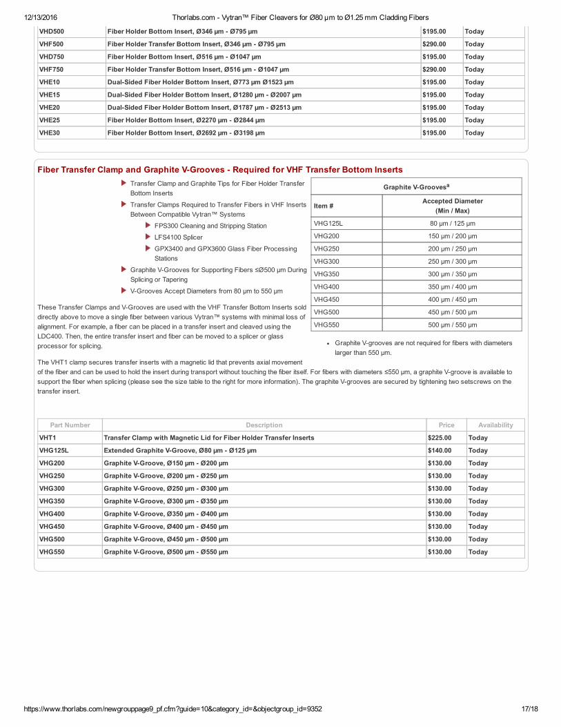
Graphite VGroovesa
Item #Accepted Diameter
(Min / Max)
VHG125L 80 µm / 125 µm
VHG200 150 µm / 200 µm
VHG250 200 µm / 250 µm
VHG300 250 µm / 300 µm
VHG350 300 µm / 350 µm
VHG400 350 µm / 400 µm
VHG450 400 µm / 450 µm
VHG500 450 µm / 500 µm
VHG550 500 µm / 550 µm
Graphite Vgrooves are not required for fibers with diameterslarger than 550 µm.
VHD500 Fiber Holder Bottom Insert, Ø346 µm Ø795 µm $195.00 Today
VHF500 Fiber Holder Transfer Bottom Insert, Ø346 µm Ø795 µm $290.00 Today
VHD750 Fiber Holder Bottom Insert, Ø516 µm Ø1047 µm $195.00 Today
VHF750 Fiber Holder Transfer Bottom Insert, Ø516 µm Ø1047 µm $290.00 Today
VHE10 DualSided Fiber Holder Bottom Insert, Ø773 µm Ø1523 µm $195.00 Today
VHE15 DualSided Fiber Holder Bottom Insert, Ø1280 µm Ø2007 µm $195.00 Today
VHE20 DualSided Fiber Holder Bottom Insert, Ø1787 µm Ø2513 µm $195.00 Today
VHE25 Fiber Holder Bottom Insert, Ø2270 µm Ø2844 µm $195.00 Today
VHE30 Fiber Holder Bottom Insert, Ø2692 µm Ø3198 µm $195.00 Today
Fiber Transfer Clamp and Graphite VGrooves Required for VHF Transfer Bottom InsertsTransfer Clamp and Graphite Tips for Fiber Holder TransferBottom Inserts
Transfer Clamps Required to Transfer Fibers in VHF InsertsBetween Compatible Vytran™ Systems
FPS300 Cleaning and Stripping Station
LFS4100 Splicer
GPX3400 and GPX3600 Glass Fiber ProcessingStations
Graphite VGrooves for Supporting Fibers ≤Ø500 µm DuringSplicing or Tapering
VGrooves Accept Diameters from 80 µm to 550 µm
These Transfer Clamps and VGrooves are used with the VHF Transfer Bottom Inserts solddirectly above to move a single fiber between various Vytran™ systems with minimal loss ofalignment. For example, a fiber can be placed in a transfer insert and cleaved using theLDC400. Then, the entire transfer insert and fiber can be moved to a splicer or glassprocessor for splicing.
The VHT1 clamp secures transfer inserts with a magnetic lid that prevents axial movementof the fiber and can be used to hold the insert during transport without touching the fiber itself. For fibers with diameters ≤550 µm, a graphite Vgroove is available tosupport the fiber when splicing (please see the size table to the right for more information). The graphite Vgrooves are secured by tightening two setscrews on thetransfer insert.
Part Number Description Price Availability
VHT1 Transfer Clamp with Magnetic Lid for Fiber Holder Transfer Inserts $225.00 Today
VHG125L Extended Graphite VGroove, Ø80 µm Ø125 µm $140.00 Today
VHG200 Graphite VGroove, Ø150 µm Ø200 µm $130.00 Today
VHG250 Graphite VGroove, Ø200 µm Ø250 µm $130.00 Today
VHG300 Graphite VGroove, Ø250 µm Ø300 µm $130.00 Today
VHG350 Graphite VGroove, Ø300 µm Ø350 µm $130.00 Today
VHG400 Graphite VGroove, Ø350 µm Ø400 µm $130.00 Today
VHG450 Graphite VGroove, Ø400 µm Ø450 µm $130.00 Today
VHG500 Graphite VGroove, Ø450 µm Ø500 µm $130.00 Today
VHG550 Graphite VGroove, Ø500 µm Ø550 µm $130.00 Today

12/13/2016 Thorlabs.com Vytran™ Fiber Cleavers for Ø80 µm to Ø1.25 mm Cladding Fibers
https://www.thorlabs.com/newgrouppage9_pf.cfm?guide=10&category_id=&objectgroup_id=9352 18/18
Compatible Systems
FPC200 Fiber Preparation StationCAC400 and CAC400A Fiber CleaversLDC400 and LDC400A Fiber CleaversGPX3800 and GPX3850 Automated Glass Processors with CleaversFFS2000 and FFS2000PT Fiber Preparation and Splicing WorkstationsFFS2000PM and FFS2000WS Fiber Preparation, Splicing,and Proof Testing WorkstationsFormer Generation LDC200 Fiber Cleaver
Click to EnlargeThe blade is shipped ina protective covering.
Replacement Diamond Cleave BladeReplacement Blade for Our Fiber CleavingSystems (See List to the Right)
0.08" (2.0 mm) Long Diamond Blade
User Installable
The ACL83 Diamond Cleave Blade is a replacement blade for the Vytran™ fiberprocessing systems listed to the right. Each system is shipped with a bladeincluded.
When used with proper cleave parameters, a single location on the blade canprovide up to 5,000 cleaves (dependent on the cladding properties of the fiber
being cleaved). The blade can be positionedapproximately 10 times before replacement (assuming proper cleave parameters and usage that does not cause unexpected damage to theblade). Blade replacement instructions for each system are provided in the user manuals.
Note: Severe damage to the blade can occur if conditions cause high stress perpendicular to the edge of the blade or if incorrect parametersare used to cleave the fiber.
Part Number Description Price Availability
ACL83 Replacement Diamond Cleave Blade $600.00 Today
Visit the Vytran™ Fiber Cleavers for Ø80 µm to Ø1.25 mm Cladding Fibers page for pricing and availability information:https://www.thorlabs.com/newgrouppage9.cfm?objectgroup_id=9352