
User's Manual LED Display Control System
153
LED LED LED LED Display Display Display Display Control Control Control Control System System System System User's User's User's User's Manual Manual Manual Manual Nanjing Nanjing Nanjing Nanjing DBstar DBstar DBstar DBstar Electronic Electronic Electronic Electronic Technology Technology Technology Technology Co. Co. Co. Co. Ltd. Ltd. Ltd. Ltd. March 15, 2010 Special Special Special Special instruction instruction instruction instruction: Thank Thank Thank Thank you you you you for for for for your your your your trust trust trust trust and and and and support support support support to to to to our our our our company. company. company. company. In In In In order order order order to to to to guarantee guarantee guarantee guarantee your your your your use use use use process process process process smoothly, smoothly, smoothly, smoothly, please please please please read read read read the the the the technical technical technical technical support support support support manual manual manual manual before before before before using using using using the the the the products. products. products. products.
Transcript of User's Manual LED Display Control System
LEDLEDLEDLED DisplayDisplayDisplayDisplay ControlControlControlControl SystemSystemSystemSystem
User'sUser'sUser'sUser's ManualManualManualManual
NanjingNanjingNanjingNanjing DBstarDBstarDBstarDBstarElectronicElectronicElectronicElectronic TechnologyTechnologyTechnologyTechnology Co.Co.Co.Co. Ltd.Ltd.Ltd.Ltd.
March 15, 2010
SpecialSpecialSpecialSpecial instructioninstructioninstructioninstruction:ThankThankThankThank youyouyouyou forforforfor youryouryouryour trusttrusttrusttrust andandandand supportsupportsupportsupport totototo ourourourour company.company.company.company. InInInIn orderorderorderorder totototoguaranteeguaranteeguaranteeguarantee youryouryouryour useuseuseuse processprocessprocessprocess smoothly,smoothly,smoothly,smoothly, pleasepleasepleaseplease readreadreadread thethethethe technicaltechnicaltechnicaltechnicalsupportsupportsupportsupport manualmanualmanualmanual beforebeforebeforebefore usingusingusingusing thethethethe products.products.products.products.
2
CCCCatalogatalogatalogatalogChapterChapterChapterChapter IIII HardwareHardwareHardwareHardware ofofofof LED'sLED'sLED'sLED's controlcontrolcontrolcontrol systemsystemsystemsystem............................................................................ 6666
SectionSectionSectionSection I:I:I:I: SummarizeSummarizeSummarizeSummarize.................................................................................................................................................................................................................... 61.1.11.1.11.1.11.1.1 FlowFlowFlowFlow chartchartchartchart exlplanationexlplanationexlplanationexlplanation ofofofof thethethethe fastfastfastfastapplicationapplicationapplicationapplication ofofofof thethethethe synchronoussynchronoussynchronoussynchronous systemsystemsystemsystem................................................................................ 66661.1.21.1.21.1.21.1.2 TypeTypeTypeType ofofofof DBT-Q2007DBT-Q2007DBT-Q2007DBT-Q2007 andandandand DBT-Q2009DBT-Q2009DBT-Q2009DBT-Q2009 controlcontrolcontrolcontrolsystemsystemsystemsystem........................................................................................................................................................................................................................................................................................................12121212SectionSectionSectionSection IIIIIIII ReviewReviewReviewReview ofofofof thethethethe performanceperformanceperformanceperformance ofofofof
DBT-QDBT-QDBT-QDBT-Q2007/2007/2007/2007/DBT-QDBT-QDBT-QDBT-Q2009200920092009 controlcontrolcontrolcontrol systemsystemsystemsystem............................................................................................................121.2.11.2.11.2.11.2.1 FunctionFunctionFunctionFunction descriptiondescriptiondescriptiondescription................................................................................................................................................................121212121.2.21.2.21.2.21.2.2 RecognitionRecognitionRecognitionRecognition ofofofof thethethethe DBT-Q2007DBT-Q2007DBT-Q2007DBT-Q2007 andandandandDBT-Q2009DBT-Q2009DBT-Q2009DBT-Q2009 hardwarehardwarehardwarehardware........................................................................................................................................................................................ 14141414
1.2.2.11.2.2.11.2.2.11.2.2.1 DBT-Q2007DBT-Q2007DBT-Q2007DBT-Q2007 fullfullfullfull colorcolorcolorcolor sendingsendingsendingsending cardcardcardcard................141414141.2.2.21.2.2.21.2.2.21.2.2.2 DBT-Q2007\DBT-Q2009DBT-Q2007\DBT-Q2009DBT-Q2007\DBT-Q2009DBT-Q2007\DBT-Q2009 receivingreceivingreceivingreceivingboardboardboardboard (HUB(HUB(HUB(HUB board)board)board)board)............................................................................................................................................................................ 171717171.2.2.31.2.2.31.2.2.31.2.2.3 DBT-Q2009DBT-Q2009DBT-Q2009DBT-Q2009 receivingreceivingreceivingreceiving cardcardcardcard (HUB(HUB(HUB(HUBboard):board):board):board):.................................................................................................................................................................................................................................................................... 19191919
1.2.31.2.31.2.31.2.3 RecognitionRecognitionRecognitionRecognition ofofofof thethethethe DBT-Q2007DBT-Q2007DBT-Q2007DBT-Q2007 andandandandDBT-Q2009DBT-Q2009DBT-Q2009DBT-Q2009 softwaresoftwaresoftwaresoftware....................................................................................................................................................................................................202020201.2.41.2.41.2.41.2.4 MainMainMainMain performanceperformanceperformanceperformance indexindexindexindex ofofofof thethethethe DBT-Q2009DBT-Q2009DBT-Q2009DBT-Q2009receivingreceivingreceivingreceiving cardcardcardcard....................................................................................................................................................................................................................................................323232321.2.51.2.51.2.51.2.5 ErrorErrorErrorError detectiondetectiondetectiondetection functionfunctionfunctionfunction.................................................................................................................................... 33333333SectionSectionSectionSection IIIIIIIIIIII TemperatureTemperatureTemperatureTemperature andandandand humidityhumidityhumidityhumidity sensorsensorsensorsensor............ 411.3.11.3.11.3.11.3.1 TheTheTheThe connectionconnectionconnectionconnection schematicschematicschematicschematic diagramdiagramdiagramdiagram isisisis asasasasfollows:follows:follows:follows:................................................................................................................................................................................................................................................................................................414141411.3.21.3.21.3.21.3.2 TheTheTheThe applicationapplicationapplicationapplication ofofofof thethethethe sensorsensorsensorsensor inininin DBT-Q2007DBT-Q2007DBT-Q2007DBT-Q2007synchronoussynchronoussynchronoussynchronous systemsystemsystemsystem........................................................................................................................................................................................................ 414141411.3.31.3.31.3.31.3.3 ApplicationApplicationApplicationApplication ofofofof thethethethe brightnessbrightnessbrightnessbrightness sensorsensorsensorsensor ininininDBDBDBDBA-A-A-A-9.09.09.09.0 asynchronousasynchronousasynchronousasynchronous systemsystemsystemsystem................................................................................................................................424242421.3.41.3.41.3.41.3.4 TheTheTheThe applicationapplicationapplicationapplication ofofofof thethethethe brightnessbrightnessbrightnessbrightness sensorsensorsensorsensor ininininDBA-7.0DBA-7.0DBA-7.0DBA-7.0 asynchronousasynchronousasynchronousasynchronous systemsystemsystemsystem................................................................................................................................43434343SectionSectionSectionSection IVIVIVIV PowerPowerPowerPower controlcontrolcontrolcontrol boardboardboardboard............................................................................................................................................441.4.11.4.11.4.11.4.1 GraphicGraphicGraphicGraphic ofofofof thethethethe realrealrealreal materialmaterialmaterialmaterial isisisis asasasas follows:follows:follows:follows:............ 444444441.4.21.4.21.4.21.4.2 2009200920092009 multifunctionalmultifunctionalmultifunctionalmultifunctional boardboardboardboard................................................................................................................45454545
ChapterChapterChapterChapter IIIIIIII AsynchronousAsynchronousAsynchronousAsynchronous controlcontrolcontrolcontrol SystemSystemSystemSystem................................................................................................................49494949SectionSectionSectionSection IIII DBA-9.0DBA-9.0DBA-9.0DBA-9.0 asynchronousasynchronousasynchronousasynchronous controlcontrolcontrolcontrol systemsystemsystemsystem........ 492.1.12.1.12.1.12.1.1 HardwareHardwareHardwareHardware recognitionrecognitionrecognitionrecognition.................................................................................................................................................... 49494949
3
2.1.22.1.22.1.22.1.2 TechnicalTechnicalTechnicalTechnical parametersparametersparametersparameters........................................................................................................................................................ 515151512.1.32.1.32.1.32.1.3 IntroductionIntroductionIntroductionIntroduction ofofofof thethethethe applicationapplicationapplicationapplication methodmethodmethodmethod............................ 52525252SectionSectionSectionSection IIIIIIII DBA-7.0DBA-7.0DBA-7.0DBA-7.0 asynchronousasynchronousasynchronousasynchronous controlcontrolcontrolcontrol systemsystemsystemsystem....
62
2.2.12.2.12.2.12.2.1 HardwareHardwareHardwareHardware recognitionrecognitionrecognitionrecognition.................................................................................................................................................... 626262622.2.22.2.22.2.22.2.2 FunctionFunctionFunctionFunction characteristiccharacteristiccharacteristiccharacteristic............................................................................................................................................ 626262622.2.32.2.32.2.32.2.3 SoftwareSoftwareSoftwareSoftware introductionintroductionintroductionintroduction andandandand applicationapplicationapplicationapplicationexplanationexplanationexplanationexplanation....................................................................................................................................................................................................................................................................63636363
2.2.3.12.2.3.12.2.3.12.2.3.1 SoftwareSoftwareSoftwareSoftware introductionintroductionintroductionintroduction............................................................................................................636363632.2.3.22.2.3.22.2.3.22.2.3.2 SoftwareSoftwareSoftwareSoftware applicationapplicationapplicationapplication.................................................................................................................... 64646464
SectionSectionSectionSection IIIIIIIIIIII VideoVideoVideoVideo processorprocessorprocessorprocessor................................................................................................................................................................752.3.12.3.12.3.12.3.1 PointsPointsPointsPoints forforforfor attentionattentionattentionattention forforforfor safetysafetysafetysafety................................................................................................ 757575752.3.22.3.22.3.22.3.2 HardwareHardwareHardwareHardware connectionconnectionconnectionconnection........................................................................................................................................................767676762.3.32.3.32.3.32.3.3 SchematicSchematicSchematicSchematic diagramdiagramdiagramdiagram ofofofof thethethethe systemsystemsystemsystem connectionconnectionconnectionconnection777777772.3.42.3.42.3.42.3.4 ExplanationExplanationExplanationExplanation ofofofof thethethethe keyboardkeyboardkeyboardkeyboard key-press:key-press:key-press:key-press:........................ 777777772.3.52.3.52.3.52.3.5 OperationOperationOperationOperation casecasecasecase........................................................................................................................................................................................................82828282
ChapterChapterChapterChapter IIIIIIIIIIII MultimediaMultimediaMultimediaMultimedia programprogramprogramprogram andandandand playingplayingplayingplaying................................................................ 84848484SectionSectionSectionSection I:I:I:I: SummarizeSummarizeSummarizeSummarize............................................................................................................................................................................................................ 843.1.13.1.13.1.13.1.1 FunctionFunctionFunctionFunction characteristiccharacteristiccharacteristiccharacteristic............................................................................................................................................ 848484843.1.23.1.23.1.23.1.2 OperatingOperatingOperatingOperating environmentenvironmentenvironmentenvironment............................................................................................................................................84848484SectionSectionSectionSection IIIIIIII InstallationInstallationInstallationInstallation andandandand unloadingunloadingunloadingunloading....................................................................................843.2.13.2.13.2.13.2.1 InstallationInstallationInstallationInstallation................................................................................................................................................................................................................................ 848484843.2.23.2.23.2.23.2.2 UnloadingUnloadingUnloadingUnloading........................................................................................................................................................................................................................................89898989SectionSectionSectionSection IIIIIIIIIIII SpecificSpecificSpecificSpecific explanationexplanationexplanationexplanation forforforfor applicationapplicationapplicationapplication 90
3.3.13.3.13.3.13.3.1 ProgramProgramProgramProgram compositioncompositioncompositioncomposition........................................................................................................................................................909090903.3.23.3.23.3.23.3.2 IntroductionIntroductionIntroductionIntroduction ofofofof thethethethe interfaceinterfaceinterfaceinterface windowwindowwindowwindow............................................ 909090903.3.33.3.33.3.33.3.3 FunctionFunctionFunctionFunction introductionintroductionintroductionintroduction.................................................................................................................................................... 92929292
3.3.3.13.3.3.13.3.3.13.3.3.1 MenuMenuMenuMenu bar:bar:bar:bar: includingincludingincludingincluding file,file,file,file, edit,edit,edit,edit, play,play,play,play,control,control,control,control, tool,tool,tool,tool, documentdocumentdocumentdocument andandandand helphelphelphelp。....................................................................929292922.3.3.22.3.3.22.3.3.22.3.3.2 ToolToolToolTool barbarbarbar............................................................................................................................................................................................101101101101
SectionSectionSectionSection IVIVIVIV EditionEditionEditionEdition ofofofof thethethethe programprogramprogramprogram materialsmaterialsmaterialsmaterials................1083.4.13.4.13.4.13.4.1 OperationOperationOperationOperation ofofofof thethethethe projectprojectprojectproject barbarbarbar................................................................................................1081081081083.4.23.4.23.4.23.4.2AddingAddingAddingAdding programprogramprogramprogram materialsmaterialsmaterialsmaterials................................................................................................................1111111111113.4.33.4.33.4.33.4.3 IntroductionIntroductionIntroductionIntroduction ofofofof thethethethe materialmaterialmaterialmaterial propertypropertypropertyproperty................................ 1111111111113.4.43.4.43.4.43.4.4 IllustrationsIllustrationsIllustrationsIllustrations withwithwithwith exampleexampleexampleexample................................................................................................................1231231231233.4.53.4.53.4.53.4.5 SubsequentSubsequentSubsequentSubsequent explanationexplanationexplanationexplanation....................................................................................................................................................125
4
SectionSectionSectionSection VVVV HowHowHowHow totototo playplayplayplay VCD/DVD/cdVCD/DVD/cdVCD/DVD/cdVCD/DVD/cd........................................................................1253.5.13.5.13.5.13.5.1 DirectDirectDirectDirect playingplayingplayingplaying.................................................................................................................................................................................................... 1251251251253.5.23.5.23.5.23.5.2 PlayingPlayingPlayingPlaying inininin thethethethe programprogramprogramprogram.................................................................................................................................... 126126126126SectionSectionSectionSection VIVIVIVI HowHowHowHow totototo playplayplayplay videovideovideovideo inputinputinputinput........................................................................................1263.6.13.6.13.6.13.6.1 New-establishedNew-establishedNew-establishedNew-established programprogramprogramprogram windowwindowwindowwindow........................................................1261261261263.6.23.6.23.6.23.6.2 SettingSettingSettingSetting thethethethe inputinputinputinput windowwindowwindowwindow ofofofof thethethethe videovideovideovideo................................ 127127127127SectionSectionSectionSection VIIVIIVIIVII howhowhowhow totototo playplayplayplay slideslideslideslide........................................................................................................................................................ 1283.7.13.7.13.7.13.7.1 PlayingPlayingPlayingPlaying....................................................................................................................................................................................................................................................1281281281283.7.23.7.23.7.23.7.2 StoppingStoppingStoppingStopping playingplayingplayingplaying................................................................................................................................................................................ 129129129129SectionSectionSectionSection VIIIVIIIVIIIVIII HowHowHowHow totototo playplayplayplay subtisubtisubtisubtittttlelelele andandandand
notificationnotificationnotificationnotification........................................................................................................................................................................................................................................................................................................................................1293.8.13.8.13.8.13.8.1 OpeningOpeningOpeningOpening thethethethe notificationnotificationnotificationnotification managementmanagementmanagementmanagementwindowwindowwindowwindow........................................................................................................................................................................................................................................................................................1291291291293.8.23.8.23.8.23.8.2 SettingSettingSettingSetting notificationnotificationnotificationnotification managementmanagementmanagementmanagement windowwindowwindowwindow........1301301301303.8.33.8.33.8.33.8.3 Playing/stoppingPlaying/stoppingPlaying/stoppingPlaying/stopping notificationnotificationnotificationnotification displaydisplaydisplaydisplay.................................... 130130130130SectionSectionSectionSection IXIXIXIXManagementManagementManagementManagement ofofofof thethethethe sportssportssportssports scorescorescorescore........................................1303.9.13.9.13.9.13.9.1 selectselectselectselect thethethethe sportssportssportssports scorescorescorescore................................................................................................................................................1301301301303.9.23.9.23.9.23.9.2 SettingSettingSettingSetting thethethethe managementmanagementmanagementmanagement ofofofof thethethethe sportssportssportssports scorescorescorescore1311311311313.9.33.9.33.9.33.9.3 Playing/stoppingPlaying/stoppingPlaying/stoppingPlaying/stopping PEPEPEPE scorescorescorescore................................................................................................................132132132132SectionSectionSectionSection XXXX ScheduleScheduleScheduleSchedule........................................................................................................................................................................................................................ 1323.10.13.10.13.10.13.10.1 OpeningOpeningOpeningOpening timingtimingtimingtiming instructioninstructioninstructioninstruction listlistlistlist........................................................................132132132132SectionSectionSectionSection XIXIXIXI NetworkNetworkNetworkNetwork controlcontrolcontrolcontrol.................................................................................................................................................... 1333.11.13.11.13.11.13.11.1 ManagementManagementManagementManagement ofofofof thethethethe remoteremoteremoteremote real-timereal-timereal-timereal-time displaydisplaydisplaydisplayscreenscreenscreenscreen....................................................................................................................................................................................................................................................................................................133133133133SectionSectionSectionSection XIIXIIXIIXII BackstageBackstageBackstageBackstage playingplayingplayingplaying............................................................................................................................................ 1353.12.13.12.13.12.13.12.1 StartingStartingStartingStarting thethethethe backstagebackstagebackstagebackstage playingplayingplayingplaying........................................................................ 1351351351353.12.23.12.23.12.23.12.2 CancelingCancelingCancelingCanceling thethethethe backstagebackstagebackstagebackstage playingplayingplayingplaying............................................................135135135135SectionSectionSectionSection XIIIXIIIXIIIXIII Multi-screenMulti-screenMulti-screenMulti-screen combinationcombinationcombinationcombination............................................................1373.13.13.13.13.13.13.13.1 EnteringEnteringEnteringEntering thethethethe synchronizationsynchronizationsynchronizationsynchronization ofofofof thethethethemulti-screenmulti-screenmulti-screenmulti-screen combinationcombinationcombinationcombination........................................................................................................................................................ 137137137137SectionSectionSectionSection XIVXIVXIVXIV SoftwareSoftwareSoftwareSoftware settingsettingsettingsetting........................................................................................................................................ 1393.14.13.14.13.14.13.14.1 OpeningOpeningOpeningOpening thethethethe settingsettingsettingsetting ofofofof thethethethe softwaresoftwaresoftwaresoftware optionoptionoptionoption139139139139
ChapterChapterChapterChapter IVIVIVIV AccessoryAccessoryAccessoryAccessory................................................................................................................................................................................................................................ 142142142142SectionSectionSectionSection IIII SettingSettingSettingSetting ofofofof thethethethe commoncommoncommoncommon displaydisplaydisplaydisplay cardcardcardcard........1424.1.14.1.14.1.14.1.1ATI-AGP/PCIATI-AGP/PCIATI-AGP/PCIATI-AGP/PCI seriesseriesseriesseries displaydisplaydisplaydisplay cardcardcardcard............................................................ 142142142142
5
4.1.24.1.24.1.24.1.2 NVDIANVDIANVDIANVDIA seriesseriesseriesseries ofofofof displaydisplaydisplaydisplay cardscardscardscards....................................................................................143143143143SectionSectionSectionSection IIIIIIII manufacturingmanufacturingmanufacturingmanufacturing ofofofof thethethethe communicationcommunicationcommunicationcommunication
linelinelineline........................................................................................................................................................................................................................................................................................................................................................................................................1464.2.14.2.14.2.14.2.1 InternationallyInternationallyInternationallyInternationally standardstandardstandardstandard typetypetypetype........................................................................................1461461461464.2.24.2.24.2.24.2.2 SpecialSpecialSpecialSpecial explanationexplanationexplanationexplanation................................................................................................................................................................148148148148
ChapterChapterChapterChapter VVVV CommonCommonCommonCommon problemsproblemsproblemsproblems........................................................................................................................................................................150150150150SectionSectionSectionSection IIII SynchronousSynchronousSynchronousSynchronous controlcontrolcontrolcontrol systemsystemsystemsystem....................................................................1505.1.15.1.15.1.15.1.1 InterruptionInterruptionInterruptionInterruption ofofofof thethethethe connectionconnectionconnectionconnection....................................................................................1501501501505.1.25.1.25.1.25.1.2 No-signalNo-signalNo-signalNo-signal outputoutputoutputoutput....................................................................................................................................................................................150150150150SectionSectionSectionSection IIIIIIII AsynchronousAsynchronousAsynchronousAsynchronous controlcontrolcontrolcontrol systemsystemsystemsystem....................................................1505.2.15.2.15.2.15.2.1 FailureFailureFailureFailure totototo startstartstartstart normallynormallynormallynormally........................................................................................................................ 1501501501505.2.25.2.25.2.25.2.2 FailureFailureFailureFailure totototo sendsendsendsend thethethethe contentcontentcontentcontent normallynormallynormallynormally........................................151151151151
6
ChapterChapterChapterChapter IIII HardwareHardwareHardwareHardware ofofofof LED'sLED'sLED'sLED'sccccontrolontrolontrolontrol ssssystemystemystemystem
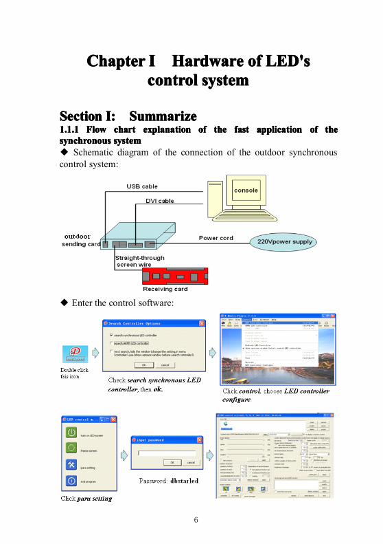
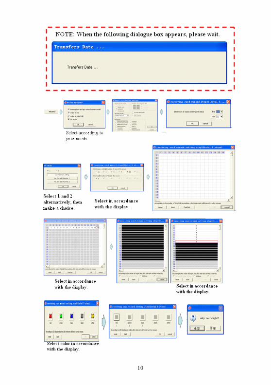
SectionSectionSectionSection I:I:I:I: SummarizeSummarizeSummarizeSummarize1.1.11.1.11.1.11.1.1 FlowFlowFlowFlow chartchartchartchart explanationexplanationexplanationexplanation ofofofof thethethethe fastfastfastfast applicationapplicationapplicationapplication ofofofof thethethethesynchronoussynchronoussynchronoussynchronous systemsystemsystemsystem◆ Schematic diagram of the connection of the outdoor synchronouscontrol system:
◆ Enter the control software:

7
◆ Specific description of the establishment of the dialogue box of theLED control system:
8
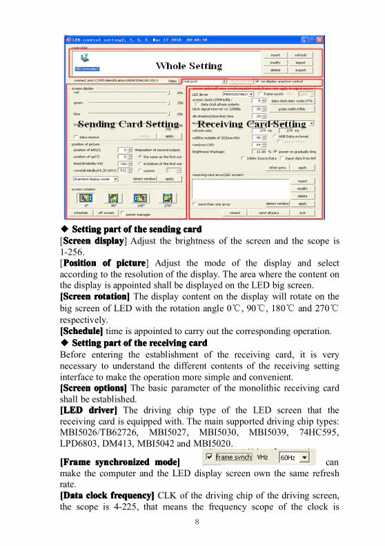
◆ SettingSettingSettingSetting partpartpartpart ofofofof thethethethe sendingsendingsendingsending cardcardcardcard[ScreenScreenScreenScreen displaydisplaydisplaydisplay] Adjust the brightness of the screen and the scope is1-256.[PositionPositionPositionPosition ofofofof picturepicturepicturepicture] Adjust the mode of the display and selectaccording to the resolution of the display. The area where the content onthe display is appointed shall be displayed on the LED big screen.[Screen[Screen[Screen[Screen rotation]rotation]rotation]rotation] The display content on the display will rotate on thebig screen of LED with the rotation angle 0℃, 90℃, 180℃ and 270℃respectively.[Schedule][Schedule][Schedule][Schedule] time is appointed to carry out the corresponding operation.◆ SettingSettingSettingSetting partpartpartpart ofofofof thethethethe receivingreceivingreceivingreceiving cardcardcardcardBefore entering the establishment of the receiving card, it is verynecessary to understand the different contents of the receiving settinginterface to make the operation more simple and convenient.[Screen[Screen[Screen[Screen options]options]options]options] The basic parameter of the monolithic receiving cardshall be established.[LED[LED[LED[LED driver]driver]driver]driver] The driving chip type of the LED screen that thereceiving card is equipped with. The main supported driving chip types:MBI5026/TB62726, MBI5027, MBI5030, MBI5039, 74HC595,LPD6803, DM413, MBI5042 and MBI5020.
[Frame[Frame[Frame[Frame synchronizedsynchronizedsynchronizedsynchronized mode]mode]mode]mode] canmake the computer and the LED display screen own the same refreshrate.[Dat[Dat[Dat[Dataaaa clockclockclockclock frequency]frequency]frequency]frequency] CLK of the driving chip of the driving screen,the scope is 4-225, that means the frequency scope of the clock is
9
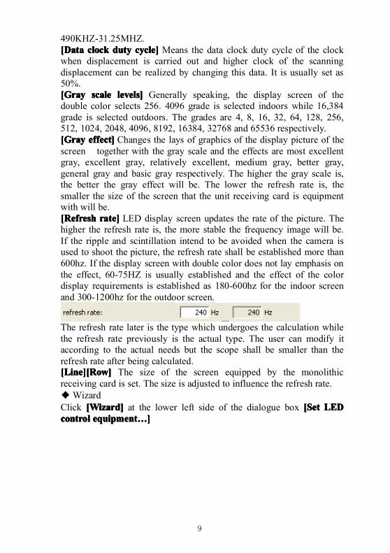
490KHZ-31.25MHZ.[Data[Data[Data[Data clockclockclockclock dutydutydutyduty cycle]cycle]cycle]cycle] Means the data clock duty cycle of the clockwhen displacement is carried out and higher clock of the scanningdisplacement can be realized by changing this data. It is usually set as50%.[Gray[Gray[Gray[Gray scalescalescalescale levels]levels]levels]levels] Generally speaking, the display screen of thedouble color selects 256. 4096 grade is selected indoors while 16,384grade is selected outdoors. The grades are 4, 8, 16, 32, 64, 128, 256,512, 1024, 2048, 4096, 8192, 16384, 32768 and 65536 respectively.[Gray[Gray[Gray[Gray effect]effect]effect]effect] Changes the lays of graphics of the display picture of thescreen together with the gray scale and the effects are most excellentgray, excellent gray, relatively excellent, medium gray, better gray,general gray and basic gray respectively. The higher the gray scale is,the better the gray effect will be. The lower the refresh rate is, thesmaller the size of the screen that the unit receiving card is equipmentwith will be.[Refresh[Refresh[Refresh[Refresh rate]rate]rate]rate] LED display screen updates the rate of the picture. Thehigher the refresh rate is, the more stable the frequency image will be.If the ripple and scintillation intend to be avoided when the camera isused to shoot the picture, the refresh rate shall be established more than600hz. If the display screen with double color does not lay emphasis onthe effect, 60-75HZ is usually established and the effect of the colordisplay requirements is established as 180-600hz for the indoor screenand 300-1200hz for the outdoor screen.
The refresh rate later is the type which undergoes the calculation whilethe refresh rate previously is the actual type. The user can modify itaccording to the actual needs but the scope shall be smaller than therefresh rate after being calculated.[Line][Row][Line][Row][Line][Row][Line][Row] The size of the screen equipped by the monolithicreceiving card is set. The size is adjusted to influence the refresh rate.◆WizardClick [Wizard][Wizard][Wizard][Wizard] at the lower left side of the dialogue box [Set[Set[Set[Set LEDLEDLEDLEDcontrolcontrolcontrolcontrol equipmentequipmentequipmentequipment…………]]]]
10
11
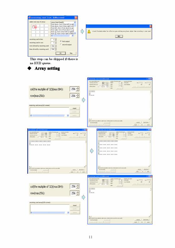
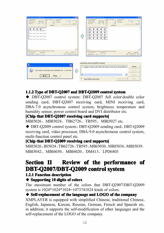
◆ ArrayArrayArrayArray settingsettingsettingsetting
12
1.1.21.1.21.1.21.1.2 TypeTypeTypeType ofofofof DBT-Q2007DBT-Q2007DBT-Q2007DBT-Q2007 andandandand DBT-Q2009DBT-Q2009DBT-Q2009DBT-Q2009 controlcontrolcontrolcontrol systemsystemsystemsystem◆ DBT-Q2007 control system: DBT-Q2007 full color\double colorsending card, DBT-Q2007 receiving card, MINI receiving card,DBA-7.0 asynchronous control system, brightness temperature andhumidity sensor, power control board and DVI distributor etc.[Chip[Chip[Chip[Chip thatthatthatthat DBT-QDBT-QDBT-QDBT-Q2007200720072007 receivingreceivingreceivingreceiving cardcardcardcard supports]supports]supports]supports]MBI5026、MBI5024、TB62726、TB595、MBI5027 etc.◆ DBT-Q2009 control system:DBT-Q2009 sending card、DBT-Q2009receiving card, video processor, DBA-9.0 asynchronous control system,multi-function control panel etc.[Chip[Chip[Chip[Chip thatthatthatthat DBT-Q2009DBT-Q2009DBT-Q2009DBT-Q2009 receivingreceivingreceivingreceiving cardcardcardcard supports]supports]supports]supports]MBI5026、BI5024、TB62726、TB595、MBI5030、MBI5036、MBI5039、
MBI5042、MBI6030、MBI6020、DM413、LPD6803
SectionSectionSectionSection IIIIIIII ReviewReviewReviewReview ofofofof thethethethe performanceperformanceperformanceperformance ofofofofDBT-QDBT-QDBT-QDBT-Q2007/2007/2007/2007/DBT-QDBT-QDBT-QDBT-Q2009200920092009 controlcontrolcontrolcontrol systemsystemsystemsystem1.2.11.2.11.2.11.2.1 FunctionFunctionFunctionFunction descriptiondescriptiondescriptiondescription◆ SupportingSupportingSupportingSupporting 10101010 digitsdigitsdigitsdigits ofofofof colorscolorscolorscolorsThe maximum number of the colors that DBT-Q2007\DBT-Q2009system is 1024*1024*1024=1073741824 kinds of colors.◆ Self-replacementSelf-replacementSelf-replacementSelf-replacement ofofofof thethethethe languagelanguagelanguagelanguage andandandand LOGOLOGOLOGOLOGO ofofofof thethethethe companycompanycompanycompanyXMPLAYER is equipped with simplified Chinese, traditional Chinese,English, Japanese, Korean, Russian, German, French and Spanish etc.in addition; it supports the self-modification of other languages and theself-replacement of the LOGO of the company.
13
◆ SupportingSupportingSupportingSupporting multiplemultiplemultiplemultiple scanscanscanscan modesmodesmodesmodesDBT-Q2007 and DBT-Q2009 systems support: static, 2 scan, 4 scan, 8scan, 16 scan and other scan modes.◆ SupportingSupportingSupportingSupporting thethethethe drivingdrivingdrivingdriving chipschipschipschips withwithwithwith PWMPWMPWMPWMThe coordination of the professional chip is entailed to make the effectof the display screen more perfect.◆ SupportingSupportingSupportingSupporting thethethethe pointpointpointpoint bybybyby pointpointpointpoint revisionrevisionrevisionrevision functionfunctionfunctionfunction ofofofof thethethethe hardwarehardwarehardwarehardwareDBT-Q2009 system supports point by point revision which supportssingle point, 2*2point, 4*4point and 8*8point the four modes. Thelargest receiving card with single sheet supports the revision of128*128 point.◆ SupportingSupportingSupportingSupporting thethethethe functionfunctionfunctionfunction ofofofof thethethethe errorerrorerrorerror detectiondetectiondetectiondetectionDBT-Q2009 system supports the function of the error detection but thecoordination of the MBI5030\MBI5039\MBI5036 driving chip isneeded to dynamically inspect the flow situation of the display screen.◆ GigabitGigabitGigabitGigabit technologytechnologytechnologytechnologyThis is definitely the perfect gigabit. The standard of the sending cardwith single sheet can own 1280*1024 resolution and the maximumamount that it can take with is 2048*600 resolution. The single net wirecan utmost be equipped with 2048*300 resolution.◆ GigabitGigabitGigabitGigabit networknetworknetworknetwork cardcardcardcard replacingreplacingreplacingreplacing thethethethe sendingsendingsendingsending cardcardcardcard andandandand displaydisplaydisplaydisplaycardcardcardcard directlydirectlydirectlydirectlyThe gigabit network card can be equipped with point screen of thereceiving card instead of the sending card and display card directly.Disadvantage: the configuration of the computer is required higher (theusage rate of CPU is extremely high) and the screen with smaller scopecan be equipped with limited functions.◆ ArbitraryArbitraryArbitraryArbitrary settingsettingsettingsetting ofofofof thethethethe graygraygraygray andandandand refreshrefreshrefreshrefresh raterateraterateThe clients can adjust between the non-gray and 65, 536 grade (64K)gray arbitrarily according to the situation of the display screen; therefresh rate can also be adjusted on a manual basis to make your displayscreen reach the best display effect.◆ HotHotHotHot standbystandbystandbystandby functionfunctionfunctionfunction ofofofof thethethethe doubledoubledoubledouble netnetnetnet wireswireswireswiresBoth A and B port of the receiving card can be used as the input oroutput, and they can also be used for two computers to control the samescreen. When one computer encounters some problems, the other onewill replace it automatically for controlling or the double net wires ofone computer can be used for controlling. When one net wireencounters some problems, the other one will replace it automaticallyfor controlling to guarantee the normal work of the display screen to theutmost.◆ SoundSoundSoundSound transmissiontransmissiontransmissiontransmission functionfunctionfunctionfunction
14
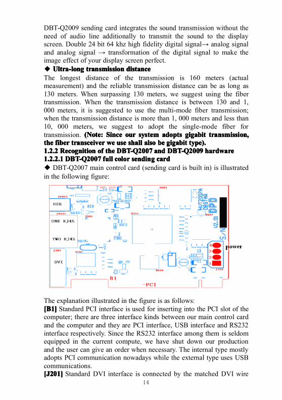
DBT-Q2009 sending card integrates the sound transmission without theneed of audio line additionally to transmit the sound to the displayscreen. Double 24 bit 64 khz high fidelity digital signal→ analog signaland analog signal → transformation of the digital signal to make theimage effect of your display screen perfect.◆ Ultra-longUltra-longUltra-longUltra-long transmissiontransmissiontransmissiontransmission distancedistancedistancedistanceThe longest distance of the transmission is 160 meters (actualmeasurement) and the reliable transmission distance can be as long as130 meters. When surpassing 130 meters, we suggest using the fibertransmission. When the transmission distance is between 130 and 1,000 meters, it is suggested to use the multi-mode fiber transmission;when the transmission distance is more than 1, 000 meters and less than10, 000 meters, we suggest to adopt the single-mode fiber fortransmission. (Note:(Note:(Note:(Note: SSSSinceinceinceince ourourourour systemsystemsystemsystem adoptsadoptsadoptsadopts gigabitgigabitgigabitgigabit transmission,transmission,transmission,transmission,thethethethe fiberfiberfiberfiber transceivertransceivertransceivertransceiver wewewewe useuseuseuse shallshallshallshall alsoalsoalsoalso bebebebe gigabitgigabitgigabitgigabit type).type).type).type).1.2.21.2.21.2.21.2.2 RecognitionRecognitionRecognitionRecognition ofofofof thethethethe DBT-Q2007DBT-Q2007DBT-Q2007DBT-Q2007 andandandand DBT-Q2009DBT-Q2009DBT-Q2009DBT-Q2009 hardwarehardwarehardwarehardware1.2.2.11.2.2.11.2.2.11.2.2.1 DBT-Q2007DBT-Q2007DBT-Q2007DBT-Q2007 fullfullfullfull colorcolorcolorcolor sendingsendingsendingsending cardcardcardcard◆ DBT-Q2007 main control card (sending card is built in) is illustratedin the following figure:
The explanation illustrated in the figure is as follows:[B1][B1][B1][B1] Standard PCI interface is used for inserting into the PCI slot of thecomputer; there are three interface kinds between our main control cardand the computer and they are PCI interface, USB interface and RS232interface respectively. Since the RS232 interface among them is seldomequipped in the current compute, we have shut down our productionand the user can give an order when necessary. The internal type mostlyadopts PCI communication nowadays while the external type uses USBcommunications.[J201][J201][J201][J201] Standard DVI interface is connected by the matched DVI wire
15
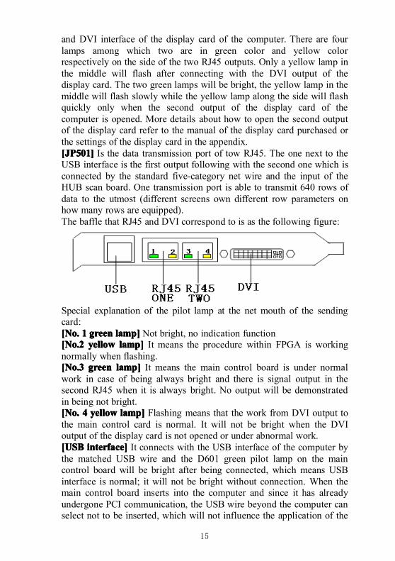
and DVI interface of the display card of the computer. There are fourlamps among which two are in green color and yellow colorrespectively on the side of the two RJ45 outputs. Only a yellow lamp inthe middle will flash after connecting with the DVI output of thedisplay card. The two green lamps will be bright, the yellow lamp in themiddle will flash slowly while the yellow lamp along the side will flashquickly only when the second output of the display card of thecomputer is opened. More details about how to open the second outputof the display card refer to the manual of the display card purchased orthe settings of the display card in the appendix.[JP501][JP501][JP501][JP501] Is the data transmission port of tow RJ45. The one next to theUSB interface is the first output following with the second one which isconnected by the standard five-category net wire and the input of theHUB scan board. One transmission port is able to transmit 640 rows ofdata to the utmost (different screens own different row parameters onhow many rows are equipped).The baffle that RJ45 and DVI correspond to is as the following figure:
Special explanation of the pilot lamp at the net mouth of the sendingcard:[No.[No.[No.[No. 1111 greengreengreengreen lamp]lamp]lamp]lamp] Not bright, no indication function[No.2[No.2[No.2[No.2 yellowyellowyellowyellow lamp]lamp]lamp]lamp] It means the procedure within FPGA is workingnormally when flashing.[No.3[No.3[No.3[No.3 greengreengreengreen lamp]lamp]lamp]lamp] It means the main control board is under normalwork in case of being always bright and there is signal output in thesecond RJ45 when it is always bright. No output will be demonstratedin being not bright.[No.[No.[No.[No. 4444 yellowyellowyellowyellow lamp]lamp]lamp]lamp] Flashing means that the work from DVI output tothe main control card is normal. It will not be bright when the DVIoutput of the display card is not opened or under abnormal work.[USB[USB[USB[USB interface]interface]interface]interface] It connects with the USB interface of the computer bythe matched USB wire and the D601 green pilot lamp on the maincontrol board will be bright after being connected, which means USBinterface is normal; it will not be bright without connection. When themain control board inserts into the computer and since it has alreadyundergone PCI communication, the USB wire beyond the computer canselect not to be inserted, which will not influence the application of the
16
control system.
Note:Note:Note:Note:WhenWhenWhenWhen USBUSBUSBUSB interfaceinterfaceinterfaceinterface isisisis adoptedadoptedadoptedadopted forforforfor connection,connection,connection,connection, pleasepleasepleaseplease connectconnectconnectconnect withwithwithwiththethethethe USBUSBUSBUSB outputoutputoutputoutput onononon thethethethe mainmainmainmain boardboardboardboard directlydirectlydirectlydirectly andandandand thenthenthenthen makemakemakemake suresuresuresureyouryouryouryour computercomputercomputercomputer doesdoesdoesdoes notnotnotnot existexistexistexist virus,virus,virus,virus, sincesincesincesince somesomesomesome kindskindskindskinds ofofofof virusvirusvirusvirus maymaymaymayprobablyprobablyprobablyprobably closeclosecloseclose thethethethe USBUSBUSBUSB interface.interface.interface.interface.
[DVI[DVI[DVI[DVI interface]interface]interface]interface] It connects with DVI output of the display card. Whenthe second output (DVI) port of the display card is opened, No. 1 andNo. 3 green lamps and No. 4 green lamp will be bright at the same timeand No. 4 yellow lamp will flash continuously.[JP602][JP602][JP602][JP602] Standard USB-B type socket is used for the communicationwith computer. When the main control card has been inserted into thePCI slot of the computer, USB communication wire can select not to beinserted. Since the main control has carried out communication withcomputer by means of PCI. If the USB wire is inserted at the same time,it will not influence the communication with computer.[D601][D601][D601][D601] The green pilot lamp will be bright when the communicationwire between the USB wire and the computer has been inserted. Thelamp will not be bright on condition that the communication wire hasnot inserted or USB interface of the computer is unable to carry outcommunication.[D102][D102][D102][D102] The red pilot lamp will be bright when main control card isinserted into the computer or powers up by means of J102, whichmeans normal electrifying. If the lamp is not bright after the maincontrol card is inserted into the computer or carries out directelectrifying, please never carry out other work before making it clear inorder to avoid the damage of the main control card.[J102][J102][J102][J102] This is the input of the power, among which No.1 and No. 3connect with +5V while No. 2 and No. 4 connect with GND ground.When the main control card is inserted into the PCI slot of the computer,it is not necessary to carry out connection. The main control card hasbeen passed through PCI to get electricity.
Note:Note:Note:Note:WhenWhenWhenWhen thethethethe mainmainmainmain controlcontrolcontrolcontrol cardcardcardcard connectsconnectsconnectsconnects withwithwithwith thethethethe computercomputercomputercomputer forforforfor thethethethefirstfirstfirstfirst time,time,time,time, pleasepleasepleaseplease presspresspresspress [send[send[send[send allallallall thethethethe parameters]parameters]parameters]parameters] withinwithinwithinwithin [LED[LED[LED[LEDcontrolcontrolcontrolcontrol setting]setting]setting]setting] panelpanelpanelpanel afterafterafterafter finishingfinishingfinishingfinishing installinginstallinginstallinginstalling thethethethe software,software,software,software, whichwhichwhichwhichisisisis equivalentequivalentequivalentequivalent totototo thethethethe initializationinitializationinitializationinitialization ofofofof thethethethe mainmainmainmain control.control.control.control.
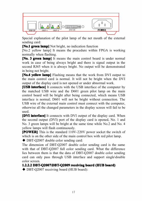
◆ The outdoor type main control of DBT-Q2007 sending card is as thefollowing figure
17
Special explanation of the pilot lamp of the net mouth of the externalsending card:[No.1[No.1[No.1[No.1 greengreengreengreen lamp]lamp]lamp]lamp] Not bright, no indication function[No.2 yellow lamp] It means the procedure within FPGA is workingnormally when flashing.[No.[No.[No.[No. 3333 greengreengreengreen lamp]lamp]lamp]lamp] It means the main control board is under normalwork in case of being always bright and there is signal output in thesecond RJ45 when it is always bright. No output will be demonstratedin being not bright.[No.4[No.4[No.4[No.4 yellowyellowyellowyellow lamp]lamp]lamp]lamp] Flashing means that the work from DVI output tothe main control card is normal. It will not be bright when the DVIoutput of the display card is not opened or under abnormal work.[USB[USB[USB[USB interface]interface]interface]interface] It connects with the USB interface of the computer bythe matched USB wire and the D601 green pilot lamp on the maincontrol board will be bright after being connected, which means USBinterface is normal; D601 will not be bright without connection. TheUSB wire of the external main control must connect with the computer,otherwise all the changed parameters in the display screen will fail to beused.[DVI[DVI[DVI[DVI interface]interface]interface]interface] It connects with DVI output of the display card. Whenthe second output (DVI) port of the display card is opened, No. 1 andNo. 3 green lamps will be bright at the same time while No.2 and No. 4yellow lamps will flash continuously.[POWER][POWER][POWER][POWER] This is the standard 110V-220V power socket the switch ofwhich is on the other side of the main control box with red pilot lamp.◆ DBT-Q2007 double color sending card:The dimension of DBT-Q2007 double color sending card is the samewith that of DBT-Q2007 full color sending card. What the differencelies between them is that the data of DBT-Q2007 double color sendingcard can only pass through USB interface and support single\doublecolor screen.1.2.2.21.2.2.21.2.2.21.2.2.2 DBT-Q2007\DBT-Q2009DBT-Q2007\DBT-Q2009DBT-Q2007\DBT-Q2009DBT-Q2007\DBT-Q2009 receivingreceivingreceivingreceiving boardboardboardboard (HUB(HUB(HUB(HUB board)board)board)board)◆ DBT-Q2007 receiving board (HUB board):
18
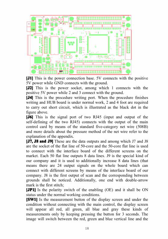
[J1][J1][J1][J1] This is the power connection base. 5V connects with the positive5V power while GND connects with the ground.[J2][J2][J2][J2] This is the power socket, among which 1 connects with thepositive 5V power while 2 and 3 connect with the ground.[J4][J4][J4][J4] This is the procedure writing port. When the procedure finisheswriting and HUB board is under normal work, 2 and 4 foot are requiredto carry out short circuit, which is illustrated as the black dot in thefigure above.[J6][J6][J6][J6] This is the signal port of two RJ45 (input and output of theself-defining of the two RJ45) connects with the output of the maincontrol card by means of the standard five-category net wire (508B)and more details about the pressure method of the net wire refer to theexplanation of the appendix.[J7,[J7,[J7,[J7, J8J8J8J8 andandandand J9]J9]J9]J9] These are the data outputs and among which J7 and J8are the socket of the flat line of 50-core and the 50-core flat line is usedto connect with the interface board of the different screens on themarket. Each 50 flat line outputs 8 data lines. J9 is the special kind ofour company and it is used to additionally increase 8 data lines (thatmeans there are 24 output signals on the whole board which canconnect with different screens by means of the interface board of ourcompany. J8 is the first output of scan and the corresponding betweengrounds shall be noticed. Additionally, one end with double-arrowmark is the first stitch;[JP1][JP1][JP1][JP1] Is the polarity switch of the enabling (OE) and it shall be ONstatus under the normal working conditions.[SW1][SW1][SW1][SW1] Is the measurement button of the display screen and under thecondition without connecting with the main control, the display screenwill appear all red, all green, all blue and gray these kinds ofmeasurements only by keeping pressing the button for 3 seconds. Theimage will switch between the red, green and blue vertical line and the
19
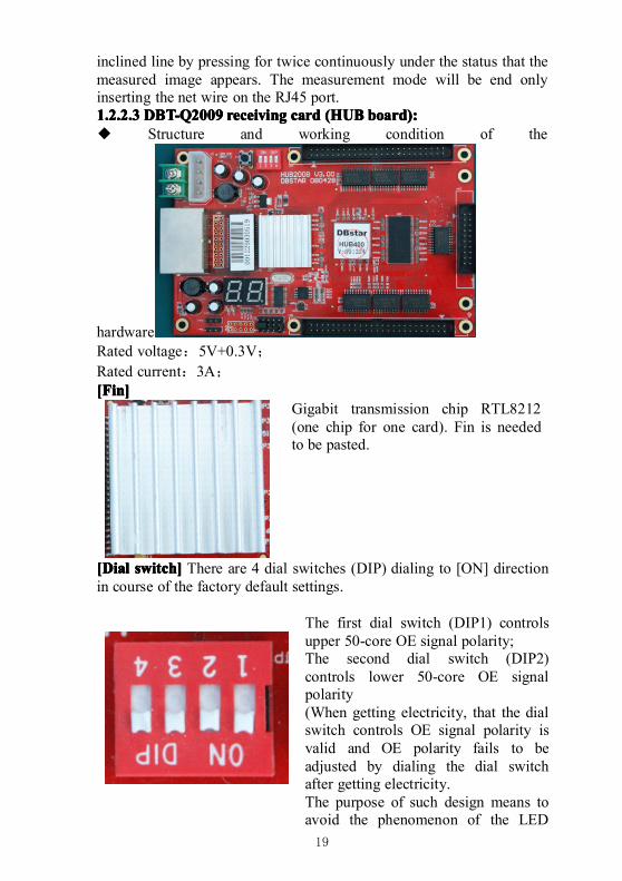
inclined line by pressing for twice continuously under the status that themeasured image appears. The measurement mode will be end onlyinserting the net wire on the RJ45 port.1.2.2.31.2.2.31.2.2.31.2.2.3 DBT-Q2009DBT-Q2009DBT-Q2009DBT-Q2009 receivingreceivingreceivingreceiving cardcardcardcard (HUB(HUB(HUB(HUB board):board):board):board):◆ Structure and working condition of the
hardwareRated voltage:5V+0.3V;Rated current:3A;[Fin][Fin][Fin][Fin]
Gigabit transmission chip RTL8212(one chip for one card). Fin is neededto be pasted.
[Dial[Dial[Dial[Dial switch]switch]switch]switch] There are 4 dial switches (DIP) dialing to [ON] directionin course of the factory default settings.
The first dial switch (DIP1) controlsupper 50-core OE signal polarity;The second dial switch (DIP2)controls lower 50-core OE signalpolarity(When getting electricity, that the dialswitch controls OE signal polarity isvalid and OE polarity fails to beadjusted by dialing the dial switchafter getting electricity.The purpose of such design means toavoid the phenomenon of the LED
20
display screen reversing these OEpolarities burns the line outputtransistor when getting electricity);The third dial switch (DIP3) is used inthe function of the receiving cardmeasuring LED module groups andmore details are illustrated in thefollowing page;The forth dial switch (DIP4) has notbeen used temporarily;
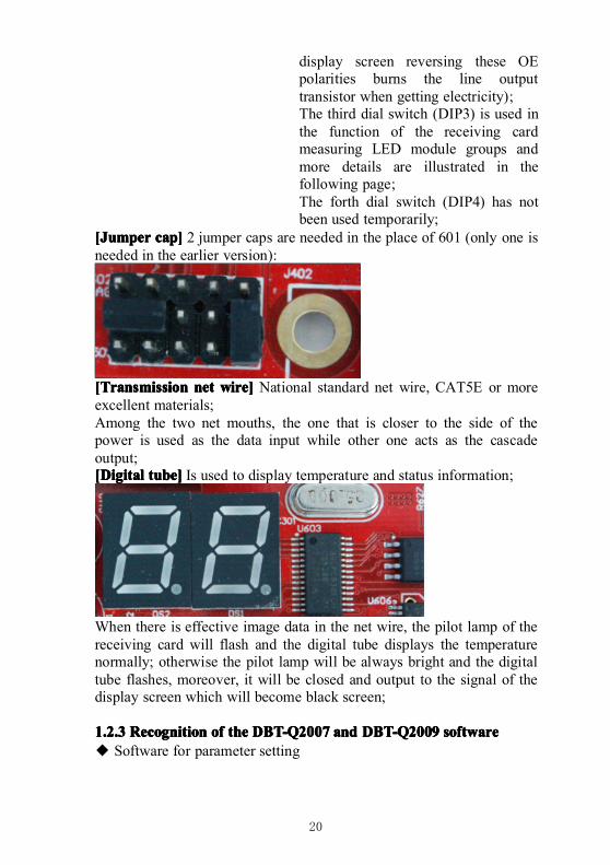
[Jumper[Jumper[Jumper[Jumper cap]cap]cap]cap] 2 jumper caps are needed in the place of 601 (only one isneeded in the earlier version):
[Transmission[Transmission[Transmission[Transmission netnetnetnet wire]wire]wire]wire] National standard net wire, CAT5E or moreexcellent materials;Among the two net mouths, the one that is closer to the side of thepower is used as the data input while other one acts as the cascadeoutput;[Digital[Digital[Digital[Digital tube]tube]tube]tube] Is used to display temperature and status information;
When there is effective image data in the net wire, the pilot lamp of thereceiving card will flash and the digital tube displays the temperaturenormally; otherwise the pilot lamp will be always bright and the digitaltube flashes, moreover, it will be closed and output to the signal of thedisplay screen which will become black screen;
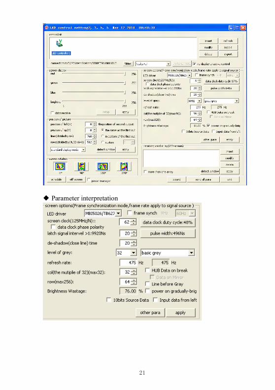
1.2.31.2.31.2.31.2.3 RecognitionRecognitionRecognitionRecognition ofofofof thethethethe DBT-Q2007DBT-Q2007DBT-Q2007DBT-Q2007 andandandand DBT-Q2009DBT-Q2009DBT-Q2009DBT-Q2009 softwaresoftwaresoftwaresoftware◆ Software for parameter setting
21
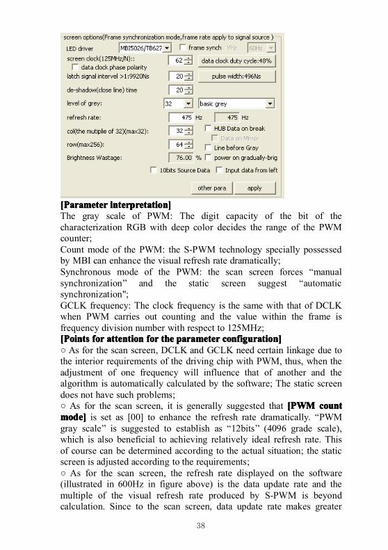
◆ Parameter interpretation
22
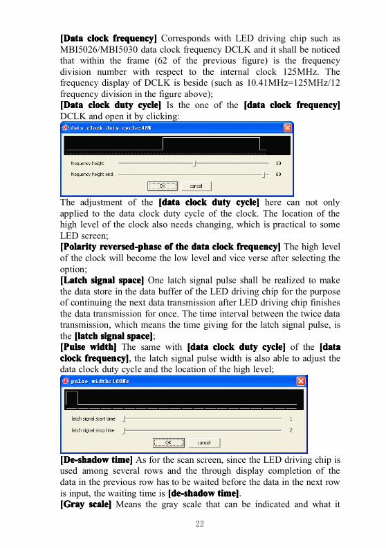
[Data[Data[Data[Data clockclockclockclock frequency]frequency]frequency]frequency] Corresponds with LED driving chip such asMBI5026/MBI5030 data clock frequency DCLK and it shall be noticedthat within the frame (62 of the previous figure) is the frequencydivision number with respect to the internal clock 125MHz. Thefrequency display of DCLK is beside (such as 10.41MHz=125MHz/12frequency division in the figure above);[Data[Data[Data[Data clockclockclockclock dutydutydutyduty cycle]cycle]cycle]cycle] Is the one of the [data[data[data[data clockclockclockclock frequency]frequency]frequency]frequency]DCLK and open it by clicking:
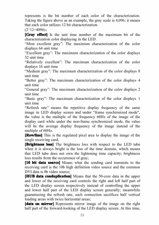
The adjustment of the [[[[ddddataataataata clockclockclockclock dutydutydutyduty cycle]cycle]cycle]cycle] here can not onlyapplied to the data clock duty cycle of the clock. The location of thehigh level of the clock also needs changing, which is practical to someLED screen;[Polarity[Polarity[Polarity[Polarity reversed-phasereversed-phasereversed-phasereversed-phase ofofofof thethethethe datadatadatadata clockclockclockclock frequency]frequency]frequency]frequency] The high levelof the clock will become the low level and vice verse after selecting theoption;[Latch[Latch[Latch[Latch signalsignalsignalsignal space]space]space]space] One latch signal pulse shall be realized to makethe data store in the data buffer of the LED driving chip for the purposeof continuing the next data transmission after LED driving chip finishesthe data transmission for once. The time interval between the twice datatransmission, which means the time giving for the latch signal pulse, isthe [latch[latch[latch[latch signalsignalsignalsignal space]space]space]space];[[[[PPPPulseulseulseulse width]width]width]width] The same with [data[data[data[data clockclockclockclock dutydutydutyduty cycle]cycle]cycle]cycle] of the [data[data[data[dataclockclockclockclock frequency]frequency]frequency]frequency], the latch signal pulse width is also able to adjust thedata clock duty cycle and the location of the high level;
[De-shadow[De-shadow[De-shadow[De-shadow time]time]time]time] As for the scan screen, since the LED driving chip isused among several rows and the through display completion of thedata in the previous row has to be waited before the data in the next rowis input, the waiting time is [de-shadow[de-shadow[de-shadow[de-shadow time]time]time]time].[Gray[Gray[Gray[Gray scale]scale]scale]scale] Means the gray scale that can be indicated and what it
23
represents is the bit number of each color of the characterization.Taking the figure above as an example, the gray scale is 4,096; it meansthat each color utilizes 12 bit characterization.(2^12=4096);[Gray[Gray[Gray[Gray effect]effect]effect]effect] Is the unit time number of the maximum bit of thecharacterization color displaying in the LED.“Most excellent gray”: The maximum characterization of the colordisplays 64 unit time“Excellent gray”: The maximum characterization of the color displays32 unit time“Relatively excellent”: The maximum characterization of the colordisplays 16 unit time“Medium gray”: The maximum characterization of the color displays 8unit time“Better gray”: The maximum characterization of the color displays 4unit time“General gray”: The maximum characterization of the color displays 2unit time“Basic gray”: The maximum characterization of the color displays 1unit time“Refresh rate” means the repetitive display frequency of the sameimage in LED display screen and under “frame synchronized mode",the value is the multiple of the frequency 60Hz of the image of thedisplay card while under the non-frame synchronized mode, the valuewill be the average display frequency of the image instead of themultiple of 60Hz.[Row/line][Row/line][Row/line][Row/line] This is the regulated pixel area to display the image of thesingle receiving card;[Brightness[Brightness[Brightness[Brightness loss]loss]loss]loss] The brightness loss with respect to the LED tubewhen it is always bright is the loss of the time domain, which meansthat LED tube does not own the lightening time capacity; brightnessloss results from the occurrence of gray;[10[10[10[10 bitbitbitbit datadatadatadata source]source]source]source] Means what the sending card transmits to thereceiving card is the 10b high definition video source and the commonDVI data is 8b video source;[HUB[HUB[HUB[HUB datadatadatadata conduplication]conduplication]conduplication]conduplication] Means that the 50-core data in the upperand lower of the receiving card controls the right and left half part ofthe LED display screen respectively instead of controlling the upperand lower half part of the LED display screen generally; meanwhileguaranteeing the refresh rate, such connection sacrifices half verticalloading areas with twice horizontal areas;[dat[dat[dat[dataaaa onononon mirror]mirror]mirror]mirror] Represents mirror image of the image on the righthalf part of the forward-looking of the LED display screen. At this time,
24
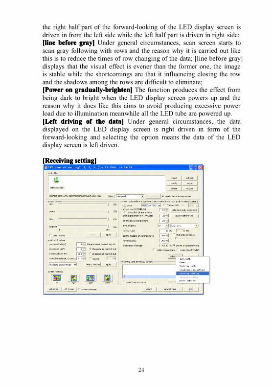
the right half part of the forward-looking of the LED display screen isdriven in from the left side while the left half part is driven in right side;[line[line[line[line beforebeforebeforebefore gray]gray]gray]gray] Under general circumstances, scan screen starts toscan gray following with rows and the reason why it is carried out likethis is to reduce the times of row changing of the data; [line before gray]displays that the visual effect is evener than the former one, the imageis stable while the shortcomings are that it influencing closing the rowand the shadows among the rows are difficult to eliminate;[Power[Power[Power[Power onononon gradually-brighten]gradually-brighten]gradually-brighten]gradually-brighten] The function produces the effect frombeing dark to bright when the LED display screen powers up and thereason why it does like this aims to avoid producing excessive powerload due to illumination meanwhile all the LED tube are powered up.[Left[Left[Left[Left drivingdrivingdrivingdriving ofofofof thethethethe data]data]data]data] Under general circumstances, the datadisplayed on the LED display screen is right driven in form of theforward-looking and selecting the option means the data of the LEDdisplay screen is left driven.
[Receiving[Receiving[Receiving[Receiving setting]setting]setting]setting]
25
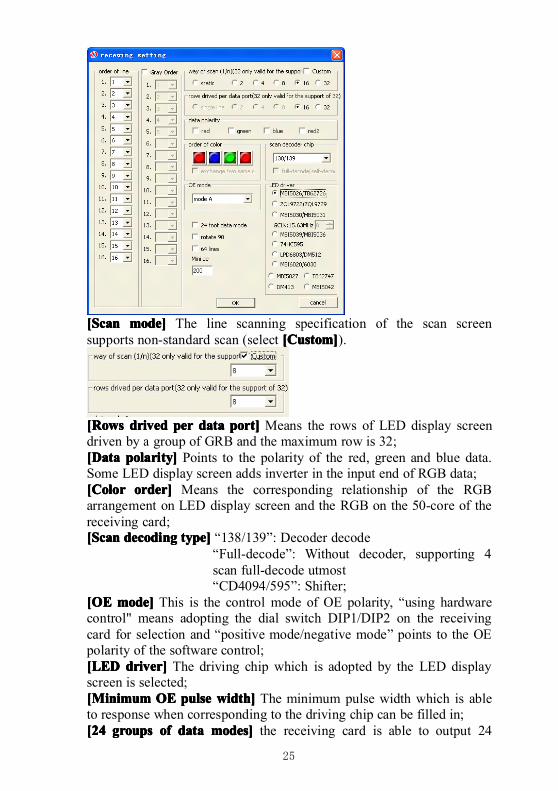
[Scan[Scan[Scan[Scan mode]mode]mode]mode] The line scanning specification of the scan screensupports non-standard scan (select [Custom][Custom][Custom][Custom]).
[[[[RRRRowsowsowsows driveddriveddriveddrived perperperper datadatadatadata port]port]port]port] Means the rows of LED display screendriven by a group of GRB and the maximum row is 32;[Data[Data[Data[Data polarity]polarity]polarity]polarity] Points to the polarity of the red, green and blue data.Some LED display screen adds inverter in the input end of RGB data;[Color[Color[Color[Color order]order]order]order] Means the corresponding relationship of the RGBarrangement on LED display screen and the RGB on the 50-core of thereceiving card;[Scan[Scan[Scan[Scan decodingdecodingdecodingdecoding type]type]type]type] “138/139”: Decoder decode
“Full-decode”: Without decoder, supporting 4scan full-decode utmost“CD4094/595”: Shifter;
[OE[OE[OE[OE mode]mode]mode]mode] This is the control mode of OE polarity, “using hardwarecontrol" means adopting the dial switch DIP1/DIP2 on the receivingcard for selection and “positive mode/negative mode” points to the OEpolarity of the software control;[LED[LED[LED[LED driver]driver]driver]driver] The driving chip which is adopted by the LED displayscreen is selected;[Minimum[Minimum[Minimum[Minimum OEOEOEOE pulsepulsepulsepulse width]width]width]width] The minimum pulse width which is ableto response when corresponding to the driving chip can be filled in;[24[24[24[24 groupsgroupsgroupsgroups ofofofof datadatadatadata modes]modes]modes]modes] the receiving card is able to output 24
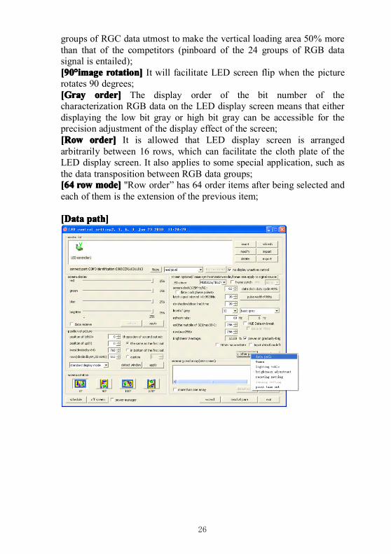
26
groups of RGC data utmost to make the vertical loading area 50% morethan that of the competitors (pinboard of the 24 groups of RGB datasignal is entailed);[90[90[90[90°°°°imageimageimageimage rotation]rotation]rotation]rotation] It will facilitate LED screen flip when the picturerotates 90 degrees;[Gray[Gray[Gray[Gray order]order]order]order] The display order of the bit number of thecharacterization RGB data on the LED display screen means that eitherdisplaying the low bit gray or high bit gray can be accessible for theprecision adjustment of the display effect of the screen;[Row[Row[Row[Row order]order]order]order] It is allowed that LED display screen is arrangedarbitrarily between 16 rows, which can facilitate the cloth plate of theLED display screen. It also applies to some special application, such asthe data transposition between RGB data groups;[64[64[64[64 rowrowrowrow mode]mode]mode]mode] "Row order” has 64 order items after being selected andeach of them is the extension of the previous item;
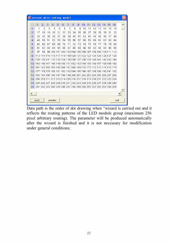
[[[[DDDDataataataata path]path]path]path]
27
Data path is the order of dot drawing when “wizard is carried out and itreflects the routing patterns of the LED module group (maximum 256pixel arbitrary routing). The parameter will be produced automaticallyafter the wizard is finished and it is not necessary for modificationunder general conditions;
28
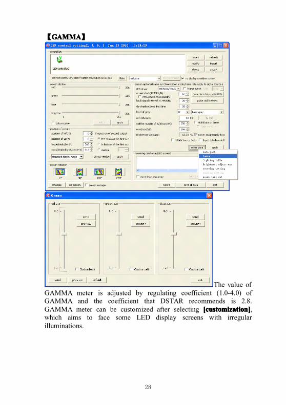
【GAMMAGAMMAGAMMAGAMMA】
The value ofGAMMA meter is adjusted by regulating coefficient (1.0-4.0) ofGAMMA and the coefficient that DSTAR recommends is 2.8.GAMMA meter can be customized after selecting [customization][customization][customization][customization],which aims to face some LED display screens with irregularilluminations.
29
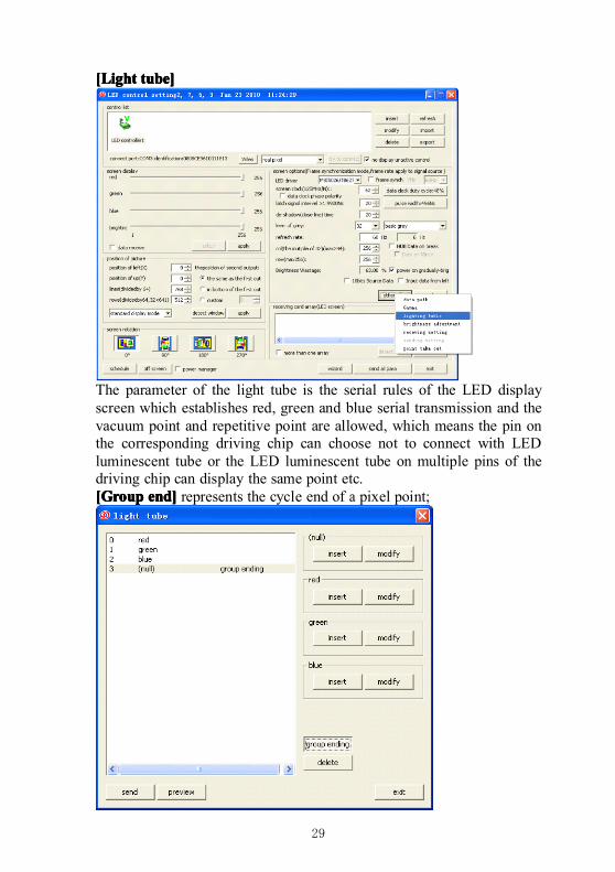
[Light[Light[Light[Light tube]tube]tube]tube]
The parameter of the light tube is the serial rules of the LED displayscreen which establishes red, green and blue serial transmission and thevacuum point and repetitive point are allowed, which means the pin onthe corresponding driving chip can choose not to connect with LEDluminescent tube or the LED luminescent tube on multiple pins of thedriving chip can display the same point etc.[Group[Group[Group[Group end]end]end]end] represents the cycle end of a pixel point;
30
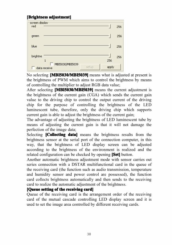
[Brightness[Brightness[Brightness[Brightness adjustment]adjustment]adjustment]adjustment]
No selecting [MBI5030/MBI5039][MBI5030/MBI5039][MBI5030/MBI5039][MBI5030/MBI5039] means what is adjusted at present isthe brightness of PWM which aims to control the brightness by meansof controlling the multiplier to adjust RGB data value;After selecting [MBI5030/MBI5039][MBI5030/MBI5039][MBI5030/MBI5039][MBI5030/MBI5039] means the current adjustment isthe brightness of the current gain (CGA) which sends the current gainvalue to the driving chip to control the output current of the drivingchip for the purpose of controlling the brightness of the LEDluminescent tube, therefore, only the driving chip which supportscurrent gain is able to adjust the brightness of the current gain;The advantage of adjusting the brightness of LED luminescent tube bymeans of adjusting the current gain is that it will not damage theperfection of the image data;Selecting [[[[CCCCollectingollectingollectingollecting data]data]data]data] means the brightness results from thebrightness sensor at the serial port of the connection computer, in thisway, that the brightness of LED display screen can be adjustedaccording to the brightness of the environment is realized and therelated configuration can be checked by opening [[[[SSSSet]et]et]et] button.Another automatic brightness adjustment mode with sensor carries outseries connection with a DSTAR multifunctional card in the queue ofthe receiving card (the function such as audio transmission, temperatureand humidity sensor and power control are possessed), the functioncard collects brightness automatically and then sends to the receivingcard to realize the automatic adjustment of the brightness.[Queue[Queue[Queue[Queue settingsettingsettingsetting ofofofof thethethethe receivingreceivingreceivingreceiving card]card]card]card]Queue of the receiving card is the arrangement order of the receivingcard of the mutual cascade controlling LED display screen and it isused to set the image area controlled by different receiving cards.
31
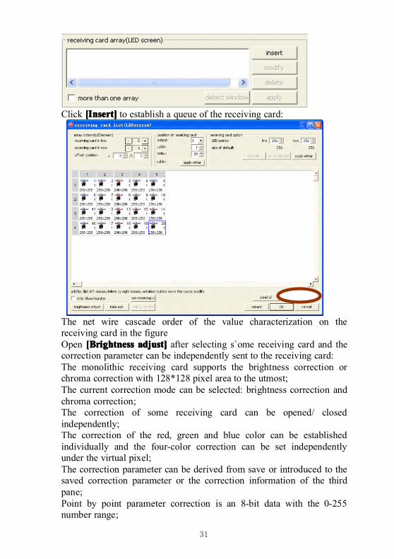
Click [[[[IIIInsert]nsert]nsert]nsert] to establish a queue of the receiving card:
The net wire cascade order of the value characterization on thereceiving card in the figureOpen [[[[BBBBrightnessrightnessrightnessrightness adjust]adjust]adjust]adjust] after selecting s`ome receiving card and thecorrection parameter can be independently sent to the receiving card:The monolithic receiving card supports the brightness correction orchroma correction with 128*128 pixel area to the utmost;The current correction mode can be selected: brightness correction andchroma correction;The correction of some receiving card can be opened/ closedindependently;The correction of the red, green and blue color can be establishedindividually and the four-color correction can be set independentlyunder the virtual pixel;The correction parameter can be derived from save or introduced to thesaved correction parameter or the correction information of the thirdpane;Point by point parameter correction is an 8-bit data with the 0-255number range;
32
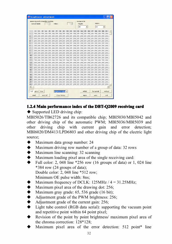
1.2.41.2.41.2.41.2.4 MainMainMainMain performanceperformanceperformanceperformance indexindexindexindex ofofofof thethethethe DBT-Q2009DBT-Q2009DBT-Q2009DBT-Q2009 receivingreceivingreceivingreceiving cardcardcardcard◆ Supported LED driving chip:MBI5026/TB62726 and its compatible chip; MBI5030/MBI5042 andother driving chip of the automatic PWM; MBI5036/MBI5039 andother driving chip with current gain and error detection;MBI6020/DM413/LPD6803 and other driving chip of the electric lightsource;◆ Maximum data group number: 24� Maximum driving row number of a group of data: 32 rows� Maximum line scanning: 32 scanning� Maximum loading pixel area of the single receiving card:� Full color: 2, 048 line *256 row (16 groups of data) or 1, 024 line
*384 row (24 groups of data);Double color: 2, 048 line *512 row;Minimum OE pulse width: 8ns;
� Maximum frequency of DCLK: 125MHz / 4 = 31.25MHz;� Maximum pixel area of the drawing dot: 256;� Maximum gray grade: 65, 536 grade (16 bit);� Adjustment grade of the PWM brightness: 256;� Adjustment grade of the current gain: 256;� Light tube control (RGB data serial): supporting the vacuum point
and repetitive point within 64 point pixel;� Revision of the point by point brightness/ maximum pixel area of
the chroma correction: 128*128;� Maximum pixel area of the error detection: 512 point* line
33
scanning* 16� Returning path error detection of 16 groups of data:The loading area will not be influenced and 20pin extended port isutilized to pass back the error detection data;
The upper and lower 50-corecontain 16 groups of RGB datawhich are used for controllingthe display of the LED screen.The extended port of 20 coreon the right contain pass-backdata which come from apass-back data group while theselection board is used toselect one group in the 16groups of the pass-back data.Error detection is carried outand passed back group bygroup.
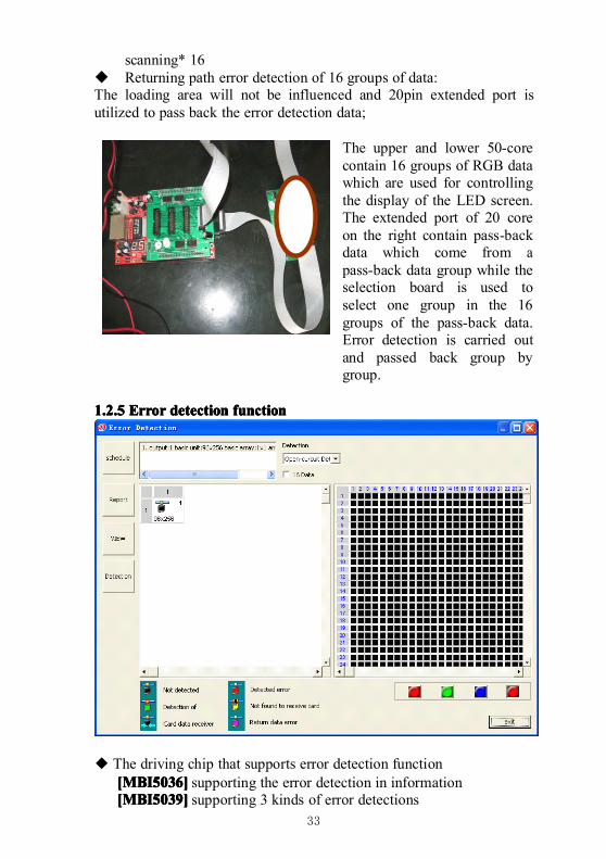
1.2.51.2.51.2.51.2.5 ErrorErrorErrorError detectiondetectiondetectiondetection functionfunctionfunctionfunction
◆ The driving chip that supports error detection function[MBI5036][MBI5036][MBI5036][MBI5036] supporting the error detection in information[MBI5039][MBI5039][MBI5039][MBI5039] supporting 3 kinds of error detections
34
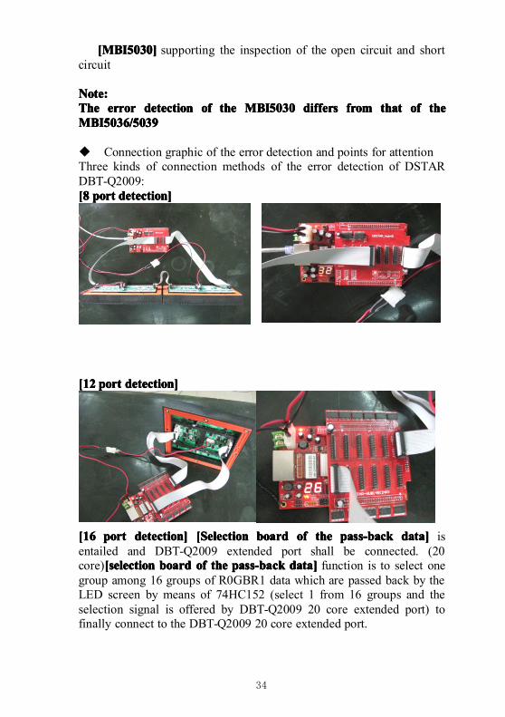
[MBI5030][MBI5030][MBI5030][MBI5030] supporting the inspection of the open circuit and shortcircuit
Note:Note:Note:Note:TheTheTheThe errorerrorerrorerror detectiondetectiondetectiondetection ofofofof thethethethe MBI5030MBI5030MBI5030MBI5030 differsdiffersdiffersdiffers fromfromfromfrom thatthatthatthat ofofofof thethethetheMBI5036/5039MBI5036/5039MBI5036/5039MBI5036/5039
� Connection graphic of the error detection and points for attentionThree kinds of connection methods of the error detection of DSTARDBT-Q2009:[8[8[8[8 portportportport detection]detection]detection]detection]
[12[12[12[12 portportportport detection]detection]detection]detection]
[16[16[16[16 portportportport detection]detection]detection]detection] [Selection[Selection[Selection[Selection boardboardboardboard ofofofof thethethethe pass-backpass-backpass-backpass-back data]data]data]data] isentailed and DBT-Q2009 extended port shall be connected. (20core)[[[[selectionselectionselectionselection boardboardboardboard ofofofof thethethethe pass-backpass-backpass-backpass-back data]data]data]data] function is to select onegroup among 16 groups of R0GBR1 data which are passed back by theLED screen by means of 74HC152 (select 1 from 16 groups and theselection signal is offered by DBT-Q2009 20 core extended port) tofinally connect to the DBT-Q2009 20 core extended port.
35
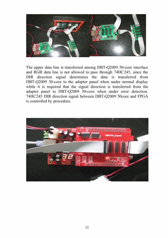
The upper data line is transferred among DBT-Q2009 50-core interfaceand RGB data line is not allowed to pass through 74HC245, since theDIR direction signal determines the data is transferred fromDBT-Q2009 50-core to the adapter panel when under normal displaywhile it is required that the signal direction is transferred from theadapter panel to DBT-Q2009 50-core when under error detection.74HC245 DIR direction signal between DBT-Q2009 50core and FPGAis controlled by procedure.
36
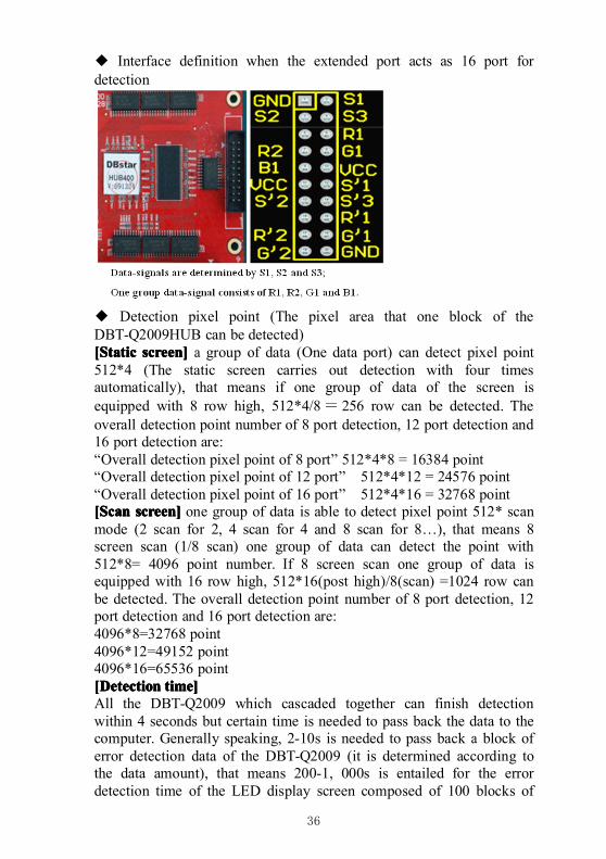
◆ Interface definition when the extended port acts as 16 port fordetection
◆ Detection pixel point (The pixel area that one block of theDBT-Q2009HUB can be detected)[Static[Static[Static[Static screen]screen]screen]screen] a group of data (One data port) can detect pixel point512*4 (The static screen carries out detection with four timesautomatically), that means if one group of data of the screen isequipped with 8 row high, 512*4/8= 256 row can be detected. Theoverall detection point number of 8 port detection, 12 port detection and16 port detection are:“Overall detection pixel point of 8 port” 512*4*8 = 16384 point“Overall detection pixel point of 12 port” 512*4*12 = 24576 point“Overall detection pixel point of 16 port” 512*4*16 = 32768 point[Scan[Scan[Scan[Scan screen]screen]screen]screen] one group of data is able to detect pixel point 512* scanmode (2 scan for 2, 4 scan for 4 and 8 scan for 8…), that means 8screen scan (1/8 scan) one group of data can detect the point with512*8= 4096 point number. If 8 screen scan one group of data isequipped with 16 row high, 512*16(post high)/8(scan) =1024 row canbe detected. The overall detection point number of 8 port detection, 12port detection and 16 port detection are:4096*8=32768 point4096*12=49152 point4096*16=65536 point[Detection[Detection[Detection[Detection time]time]time]time]All the DBT-Q2009 which cascaded together can finish detectionwithin 4 seconds but certain time is needed to pass back the data to thecomputer. Generally speaking, 2-10s is needed to pass back a block oferror detection data of the DBT-Q2009 (it is determined according tothe data amount), that means 200-1, 000s is entailed for the errordetection time of the LED display screen composed of 100 blocks of
37
DBT-Q2009 for once (4-17 minutes)[Influence[Influence[Influence[Influence ofofofof thethethethe errorerrorerrorerror detectiondetectiondetectiondetection totototo thethethethe normalnormalnormalnormal displaydisplaydisplaydisplay ofofofof thethethethe bigbigbigbigscreen]screen]screen]screen]As for the detection of In-Message, MBI5036/5039 actually can neverinfluence the normal display totally, however, it fails to detect all theerrors for once, since In-Message detection requires that display datais ’1’ and OE is in low level, which means that only the luminescenttubes can be detected. When it is in normal display, it is possible thatsome luminescent tubes are not bright. In order to detect all the errors inone time, DSTAR DBT-Q2009 adopts the method of forcing the data tobe placed ’1’ and OE is in low level, however, if doing so, the normaldisplay (LED display screen will turn white instantly) will be affectedinstantly in course of detection.As for the forced error detection, since MBI5036/5039 adopts themethod of opening the LED instantly for detection, the influence of theDBT-Q2009 receiving card to the LED big screen is very small incourse of the detection.[Points[Points[Points[Points forforforfor attentionattentionattentionattention ofofofof thethethethe shieldshieldshieldshield design]design]design]design]○ The driving chip of many scan screen OE are grounded, whichdirectly results in the failure to carry out “forced open-circuit detection”and “forced short circuit detection”. Therefore, the method of makingthe driving chip grounded is not recommended.○ The advantage of the LED driver which supports the built-in PWM ofthe built-in PWM driving chip:○ The update time of the image data is reduced to enhance the updaterate of the image data;○ The visual refresh rate of the LED display screen is enhanced (specialPWM accounting algorithm);○ Extremely excellent and low-gray representation (without theresponse problem of OE pulse width).
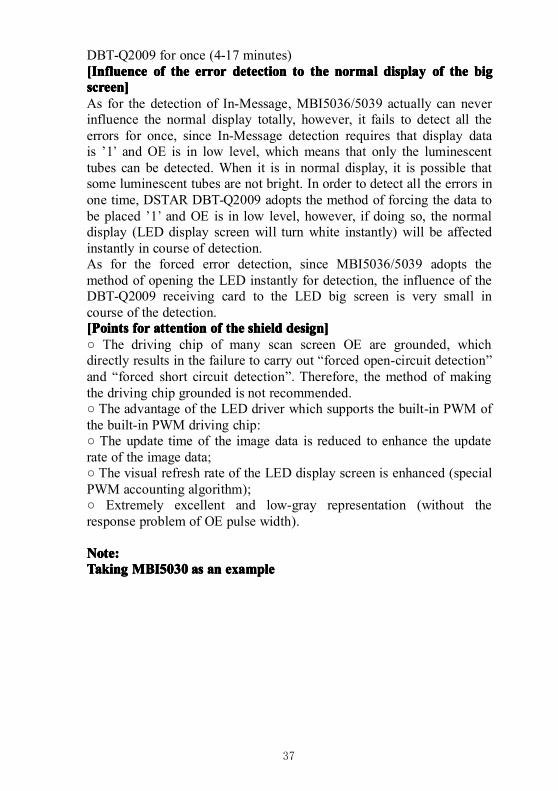
Note:Note:Note:Note:TakingTakingTakingTaking MBI5030MBI5030MBI5030MBI5030 asasasas anananan exampleexampleexampleexample
38
[Parameter[Parameter[Parameter[Parameter interpretation]interpretation]interpretation]interpretation]The gray scale of PWM: The digit capacity of the bit of thecharacterization RGB with deep color decides the range of the PWMcounter;Count mode of the PWM: the S-PWM technology specially possessedby MBI can enhance the visual refresh rate dramatically;Synchronous mode of the PWM: the scan screen forces “manualsynchronization” and the static screen suggest “automaticsynchronization";GCLK frequency: The clock frequency is the same with that of DCLKwhen PWM carries out counting and the value within the frame isfrequency division number with respect to 125MHz;[Points[Points[Points[Points forforforfor attentionattentionattentionattention forforforfor thethethethe parameterparameterparameterparameter configuration]configuration]configuration]configuration]○ As for the scan screen, DCLK and GCLK need certain linkage due tothe interior requirements of the driving chip with PWM, thus, when theadjustment of one frequency will influence that of another and thealgorithm is automatically calculated by the software; The static screendoes not have such problems;○ As for the scan screen, it is generally suggested that [PWM[PWM[PWM[PWM countcountcountcountmode]mode]mode]mode] is set as [00] to enhance the refresh rate dramatically. “PWMgray scale” is suggested to establish as “12bits” (4096 grade scale),which is also beneficial to achieving relatively ideal refresh rate. Thisof course can be determined according to the actual situation; the staticscreen is adjusted according to the requirements;○ As for the scan screen, the refresh rate displayed on the software(illustrated in 600Hz in figure above) is the data update rate and themultiple of the visual refresh rate produced by S-PWM is beyondcalculation. Since to the scan screen, data update rate makes greater
39
contribution to the visual refresh rate; as for the static screen, therefresh rate displayed on the software has calculated the multiple of theS-PWM refresh rate, therefore, the refresh rate of the static screenusually can reach thousands of values;○ [Latch[Latch[Latch[Latch signalsignalsignalsignal intervalintervalintervalinterval time]time]time]time] and [de-shadow[de-shadow[de-shadow[de-shadow time]time]time]time] can establishsmaller value, illustrated in 2;○ Order of the parameter configuration: select the driving chip-> set therow, line and scan mode etc. of the loading of the receiving card-> set“PWM gray scale” (“12 bits is suggested to be used) and “PWM countmode” ("00" is suggested to use) ->set proper GCLK frequency->carryout fine adjustment to DCLK to match with GCLK;○ The scan screen which builds in the PWM driving chip does notsupport “scan row following with gray”;○ 24 groups of data output is not supported when the PWM drivingchip is built in and only 16 groups of data output is supported.○ Application of the MBI5030/MBI5042 on RGB serial LED displayscreen (color curtain and light tube):Since the driving chip which builds in PWM reduces the update time ofthe image data significantly, data transmission can be carried out eventhough DCLK operates under a very low frequency while both thevisual refresh rate and image quality represent well, therefore, theapplication of it in RGB serial LED display screen becomes the idealchoice and the effect is much better than the common driving chip withthe constant current source (such as MBI5026);DSTAR DBT-Q2009 (DBT-Q2009) LED control system supportsMBI5030/5042 and the application of other driving chip with interiorPWM on RGB serial LED display screen as well as the vacuum pointand focal point;○ Other LED driving chip which builds in PWM (mainly with pointlight source):LPD6803LPD6803LPD6803LPD6803Only the LED driving chip of the point light source with 5-bit deepcolor is supported and used in the low-end application with relativelylow color requirements. Moreover, crystal oscillator is built in;DM413DM413DM413DM413The crystal replacement supports the LED driving chip with point lightsource with 8-bit deep color and the current gain is adjustable;MBI6020/MBI6030MBI6020/MBI6030MBI6020/MBI6030MBI6020/MBI6030MBI supports the LED driving chip with point light source with 16-bitor 10-bit deep color and the current gain is adjustable. The crystaloscillator is built in and GCLK can also be offered on an external basis;The driving chip which builds in PWM will also be supported in thelater stage:
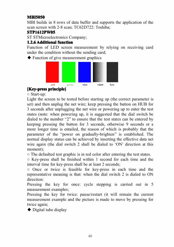
40
MBI5050MBI5050MBI5050MBI5050MBI builds in 8 rows of data buffer and supports the application of thescan screen with 2-8 scan; TC62D722: Toshiba;STP1612PW05STP1612PW05STP1612PW05STP1612PW05ST STMicroelectronics Company;1.2.61.2.61.2.61.2.6AdditionalAdditionalAdditionalAdditional functionfunctionfunctionfunctionFunction of LED screen measurement by relying on receiving cardunder the condition without the sending card;◆ Function of give measurement graphics
[Key-press[Key-press[Key-press[Key-press principle]principle]principle]principle]○ Start-up:Light the screen to be tested before starting up (the correct parameter isset) and then unplug the net wire; keep pressing the button on HUB for3 seconds after unplugging the net wire or powering up to enter the teststates (note: when powering up, it is suggested that the dial switch bedialed to the number “2” to ensure that the test states can be entered bykeeping pressing the button for 3 seconds, otherwise 9 seconds or amore longer time is entailed, the reason of which is probably that theparameter of the “power on gradually-brighten” is established. Thenormal display status can be achieved by inserting the effective data netwire again (the dial switch 2 shall be dialed to ‘ON’ direction at thismoment);○ The defaulted test graphic is in red color after entering the test states.○ Key-press shall be finished within 1 second for each time and theinterval time for key-press shall be at least 2 seconds;○ Once or twice is feasible for key-press in each time and therepresentative meaning is that: when the dial switch 2 is dialed to ONdirection:Pressing the key for once: cycle stepping is carried out in 5measurement examples;Pressing the key for twice: pause/restart (it will remain the currentmeasurement example and the picture is made to move by pressing fortwice again;◆ Digital tube display
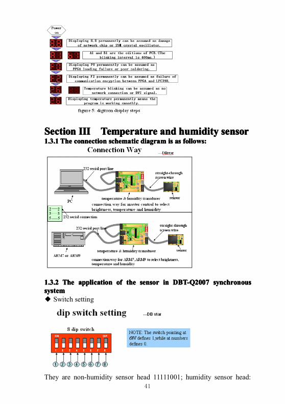
41
SectionSectionSectionSection IIIIIIIIIIII TemperatureTemperatureTemperatureTemperature andandandand humidityhumidityhumidityhumidity sensorsensorsensorsensor1.3.11.3.11.3.11.3.1 TheTheTheThe connectionconnectionconnectionconnection schematicschematicschematicschematic diagramdiagramdiagramdiagram isisisis asasasas follows:follows:follows:follows:
1.3.21.3.21.3.21.3.2 TheTheTheThe applicationapplicationapplicationapplication ofofofof thethethethe sensorsensorsensorsensor inininin DBT-Q2007DBT-Q2007DBT-Q2007DBT-Q2007 synchronoussynchronoussynchronoussynchronoussystemsystemsystemsystem◆ Switch setting
They are non-humidity sensor head 11111001; humidity sensor head:
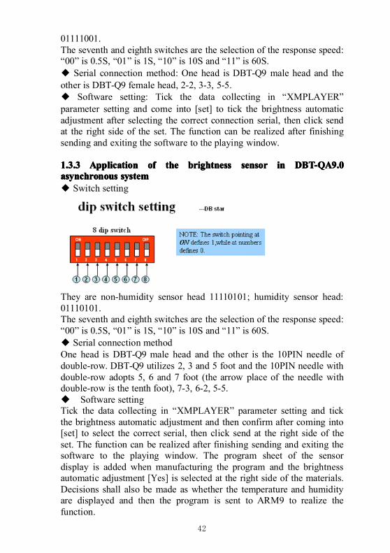
42
01111001.The seventh and eighth switches are the selection of the response speed:“00” is 0.5S, “01” is 1S, “10” is 10S and “11” is 60S.◆ Serial connection method: One head is DBT-Q9 male head and theother is DBT-Q9 female head, 2-2, 3-3, 5-5.◆ Software setting: Tick the data collecting in “XMPLAYER”parameter setting and come into [set] to tick the brightness automaticadjustment after selecting the correct connection serial, then click sendat the right side of the set. The function can be realized after finishingsending and exiting the software to the playing window.
1.3.31.3.31.3.31.3.3 ApplicationApplicationApplicationApplication ofofofof thethethethe brightnessbrightnessbrightnessbrightness sensorsensorsensorsensor inininin DBT-QA9.0DBT-QA9.0DBT-QA9.0DBT-QA9.0asynchronousasynchronousasynchronousasynchronous systemsystemsystemsystem◆ Switch setting
They are non-humidity sensor head 11110101; humidity sensor head:01110101.The seventh and eighth switches are the selection of the response speed:“00” is 0.5S, “01” is 1S, “10” is 10S and “11” is 60S.◆ Serial connection methodOne head is DBT-Q9 male head and the other is the 10PIN needle ofdouble-row. DBT-Q9 utilizes 2, 3 and 5 foot and the 10PIN needle withdouble-row adopts 5, 6 and 7 foot (the arrow place of the needle withdouble-row is the tenth foot), 7-3, 6-2, 5-5.� Software settingTick the data collecting in “XMPLAYER” parameter setting and tickthe brightness automatic adjustment and then confirm after coming into[set] to select the correct serial, then click send at the right side of theset. The function can be realized after finishing sending and exiting thesoftware to the playing window. The program sheet of the sensordisplay is added when manufacturing the program and the brightnessautomatic adjustment [Yes] is selected at the right side of the materials.Decisions shall also be made as whether the temperature and humidityare displayed and then the program is sent to ARM9 to realize thefunction.
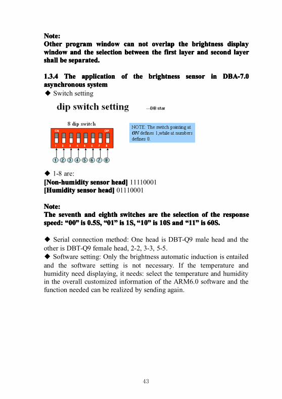
43
Note:Note:Note:Note:OtherOtherOtherOther programprogramprogramprogram windowwindowwindowwindow cancancancan notnotnotnot overlapoverlapoverlapoverlap thethethethe brightnessbrightnessbrightnessbrightness displaydisplaydisplaydisplaywindowwindowwindowwindow andandandand thethethethe selectionselectionselectionselection betweenbetweenbetweenbetween thethethethe firstfirstfirstfirst layerlayerlayerlayer andandandand secondsecondsecondsecond layerlayerlayerlayershallshallshallshall bebebebe separated.separated.separated.separated.
1.3.41.3.41.3.41.3.4 TheTheTheThe applicationapplicationapplicationapplication ofofofof thethethethe brightnessbrightnessbrightnessbrightness sensorsensorsensorsensor inininin DBA-7.0DBA-7.0DBA-7.0DBA-7.0asynchronousasynchronousasynchronousasynchronous systemsystemsystemsystem◆ Switch setting
◆ 1-8 are:[Non-humidity[Non-humidity[Non-humidity[Non-humidity sensorsensorsensorsensor head]head]head]head] 11110001[Humidity[Humidity[Humidity[Humidity sensorsensorsensorsensor head]head]head]head] 01110001
Note:Note:Note:Note:TheTheTheThe seventhseventhseventhseventh andandandand eightheightheightheighth switchesswitchesswitchesswitches areareareare thethethethe selectionselectionselectionselection ofofofof thethethethe responseresponseresponseresponsespeed:speed:speed:speed: ““““00000000”””” isisisis 0.5S,0.5S,0.5S,0.5S, ““““01010101”””” isisisis 1S,1S,1S,1S, ““““10101010”””” isisisis 10S10S10S10S andandandand ““““11111111”””” isisisis 60S.60S.60S.60S.
◆ Serial connection method: One head is DBT-Q9 male head and theother is DBT-Q9 female head, 2-2, 3-3, 5-5.◆ Software setting: Only the brightness automatic induction is entailedand the software setting is not necessary. If the temperature andhumidity need displaying, it needs: select the temperature and humidityin the overall customized information of the ARM6.0 software and thefunction needed can be realized by sending again.
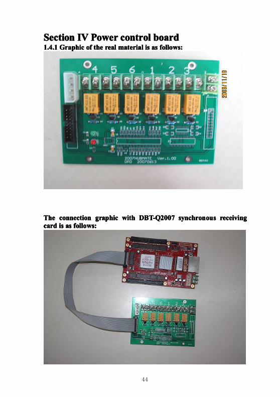
44
SectionSectionSectionSection IVIVIVIV PowerPowerPowerPower controlcontrolcontrolcontrol boardboardboardboard1.4.11.4.11.4.11.4.1 GraphicGraphicGraphicGraphic ofofofof thethethethe realrealrealreal materialmaterialmaterialmaterial isisisis asasasas follows:follows:follows:follows:
TheTheTheThe connectionconnectionconnectionconnection graphicgraphicgraphicgraphic withwithwithwith DBT-Q2007DBT-Q2007DBT-Q2007DBT-Q2007 synchronoussynchronoussynchronoussynchronous receivingreceivingreceivingreceivingcardcardcardcard isisisis asasasas follows:follows:follows:follows:
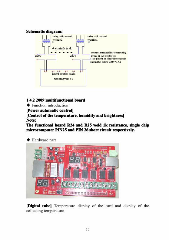
45
SchematicSchematicSchematicSchematic diagram:diagram:diagram:diagram:
1.4.21.4.21.4.21.4.2 2009200920092009 multifunctionalmultifunctionalmultifunctionalmultifunctional boardboardboardboard◆ Function introduction:[Power[Power[Power[Power automaticautomaticautomaticautomatic control]control]control]control][Control[Control[Control[Control ofofofof thethethethe temperature,temperature,temperature,temperature, humidityhumidityhumidityhumidity andandandand brightness]brightness]brightness]brightness]Note:Note:Note:Note:TheTheTheThe functionalfunctionalfunctionalfunctional boardboardboardboard R24R24R24R24 andandandand R25R25R25R25 weldweldweldweld 1k1k1k1k resistance,resistance,resistance,resistance, singlesinglesinglesingle chipchipchipchipmicrocomputermicrocomputermicrocomputermicrocomputer PIN25PIN25PIN25PIN25 andandandand PINPINPINPIN 26262626 shortshortshortshort circuitcircuitcircuitcircuit respectively.respectively.respectively.respectively.
◆ Hardware part
[Digital[Digital[Digital[Digital tube]tube]tube]tube] Temperature display of the card and display of thecollecting temperature
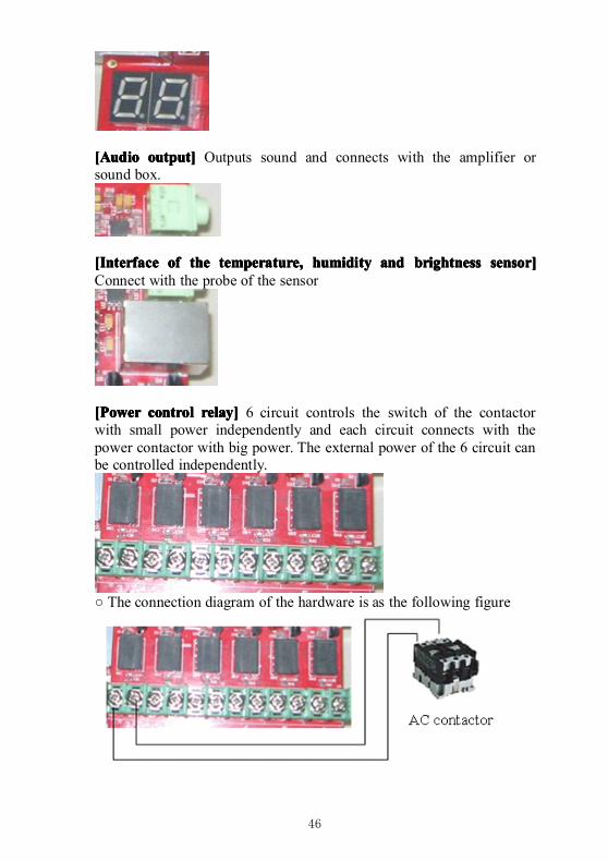
46
[Audio[Audio[Audio[Audio output]output]output]output] Outputs sound and connects with the amplifier orsound box.
[Interface[Interface[Interface[Interface ofofofof thethethethe temperature,temperature,temperature,temperature, humidityhumidityhumidityhumidity andandandand brightnessbrightnessbrightnessbrightness sensor]sensor]sensor]sensor]Connect with the probe of the sensor
[Power[Power[Power[Power controlcontrolcontrolcontrol relay]relay]relay]relay] 6 circuit controls the switch of the contactorwith small power independently and each circuit connects with thepower contactor with big power. The external power of the 6 circuit canbe controlled independently.
○ The connection diagram of the hardware is as the following figure
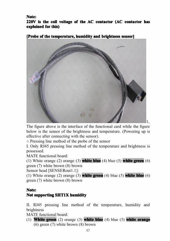
47
Note:Note:Note:Note:220V220V220V220V isisisis thethethethe coilcoilcoilcoil voltagevoltagevoltagevoltage ofofofof thethethethe ACACACAC contactorcontactorcontactorcontactor (AC(AC(AC(AC contactorcontactorcontactorcontactor hashashashasexplainedexplainedexplainedexplained forforforfor this)this)this)this)
[Probe[Probe[Probe[Probe ofofofof thethethethe temperature,temperature,temperature,temperature, humidityhumidityhumidityhumidity andandandand brightnessbrightnessbrightnessbrightness sensor]sensor]sensor]sensor]
1,The figure above is the interface of the functional card while the figurebelow is the sensor of the brightness and temperature. (Powering up iseffective after connecting with the sensor).○ Pressing line method of the probe of the sensorI. Only RJ45 pressing line method of the temperature and brightness ispossessed.MATE functional board:(1) White orange (2) orange (3) whitewhitewhitewhite blueblueblueblue (4) blue (5) whitewhitewhitewhite greengreengreengreen (6)green (7) white brown (8) brownSensor head [SENSERout1.1]:(1) White orange (2) orange (3) whitewhitewhitewhite greengreengreengreen (4) blue (5) whitewhitewhitewhite blueblueblueblue (6)green (7) white brown (8) brown
Note:Note:Note:Note:NotNotNotNot supportingsupportingsupportingsupporting SHT1XSHT1XSHT1XSHT1X humidityhumidityhumidityhumidity
II. RJ45 pressing line method of the temperature, humidity andbrightnessMATE functional board:(1) WhiteWhiteWhiteWhite greengreengreengreen (2) orange (3) whitewhitewhitewhite blueblueblueblue (4) blue (5) whitewhitewhitewhite orangeorangeorangeorange
(6) green (7) white brown (8) brown
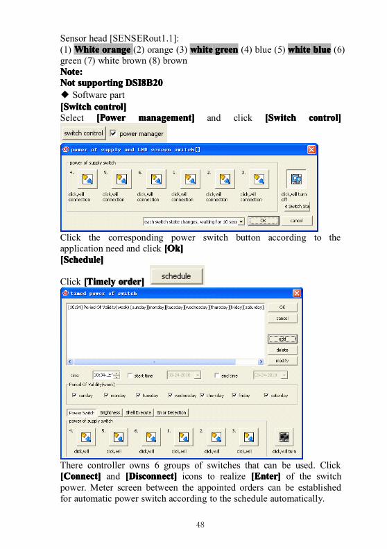
48
Sensor head [SENSERout1.1]:(1) WhiteWhiteWhiteWhite orangeorangeorangeorange (2) orange (3) whitewhitewhitewhite greengreengreengreen (4) blue (5) whitewhitewhitewhite blueblueblueblue (6)green (7) white brown (8) brownNote:Note:Note:Note:NotNotNotNot supportingsupportingsupportingsupporting DSI8B20DSI8B20DSI8B20DSI8B20◆ Software part[[[[SSSSwitchwitchwitchwitch control]control]control]control]Select [[[[PPPPowerowerowerower management]management]management]management] and click [[[[SSSSwitchwitchwitchwitch control]control]control]control]
Click the corresponding power switch button according to theapplication need and click [[[[OOOOk]k]k]k][[[[SSSSchedule]chedule]chedule]chedule]
Click [[[[TTTTimelyimelyimelyimely order]order]order]order]
There controller owns 6 groups of switches that can be used. Click[[[[CCCConnect]onnect]onnect]onnect] and [[[[DDDDisconnect]isconnect]isconnect]isconnect] icons to realize [[[[EEEEnter]nter]nter]nter] of the switchpower. Meter screen between the appointed orders can be establishedfor automatic power switch according to the schedule automatically.
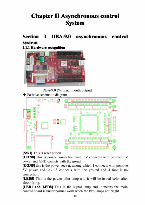
49
ChapterChapterChapterChapter IIIIIIII AsynchronousAsynchronousAsynchronousAsynchronous ccccontrolontrolontrolontrolSystemSystemSystemSystem
SectionSectionSectionSection IIII DBA-9.0DBA-9.0DBA-9.0DBA-9.0 asynchronousasynchronousasynchronousasynchronous controlcontrolcontrolcontrolsystemsystemsystemsystem2.1.12.1.12.1.12.1.1 HardwareHardwareHardwareHardware recognitionrecognitionrecognitionrecognition
DBA-9.0 (With net mouth output)◆ Positive schematic diagram
[SW1][SW1][SW1][SW1] This is reset button.[CON8][CON8][CON8][CON8] This is power connection base, 5V connects with positive 5Vpower and GND conncts with the groud.[CON5][CON5][CON5][CON5] this is the power socket, among which 1 connects with positive5V power and. 2、 3 connects with the ground and 4 foot is noconnection.[LED5][LED5][LED5][LED5] This is the power pilot lamp and it will be in red color afterelectrifying.[LED1[LED1[LED1[LED1 andandandand LED8]LED8]LED8]LED8] This is the signal lamp and it means the maincontrol board is under normal work when the two lamps are bright.
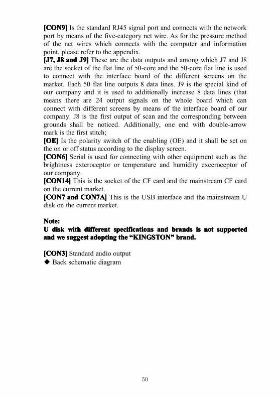
50
[CON9][CON9][CON9][CON9] Is the standard RJ45 signal port and connects with the networkport by means of the five-category net wire. As for the pressure methodof the net wires which connects with the computer and informationpoint, please refer to the appendix.[J7,[J7,[J7,[J7, J8J8J8J8 andandandand J9]J9]J9]J9] These are the data outputs and among which J7 and J8are the socket of the flat line of 50-core and the 50-core flat line is usedto connect with the interface board of the different screens on themarket. Each 50 flat line outputs 8 data lines. J9 is the special kind ofour company and it is used to additionally increase 8 data lines (thatmeans there are 24 output signals on the whole board which canconnect with different screens by means of the interface board of ourcompany. J8 is the first output of scan and the corresponding betweengrounds shall be noticed. Additionally, one end with double-arrowmark is the first stitch;[OE][OE][OE][OE] Is the polarity switch of the enabling (OE) and it shall be set onthe on or off status according to the display screen.[CON6][CON6][CON6][CON6] Serial is used for connecting with other equipment such as thebrightness exteroceptor or temperature and humidity exceroceptor ofour company.[CON14][CON14][CON14][CON14] This is the socket of the CF card and the mainstream CF cardon the current market.[CON7[CON7[CON7[CON7 andandandand CON7A]CON7A]CON7A]CON7A] This is the USB interface and the mainstream Udisk on the current market.
Note:Note:Note:Note:UUUU diskdiskdiskdisk withwithwithwith differentdifferentdifferentdifferent specificationsspecificationsspecificationsspecifications andandandand brandsbrandsbrandsbrands isisisis notnotnotnot supportedsupportedsupportedsupportedandandandand wewewewe suggestsuggestsuggestsuggest adoptingadoptingadoptingadopting thethethethe ““““KINGSTONKINGSTONKINGSTONKINGSTON”””” brand.brand.brand.brand.
[CON3][CON3][CON3][CON3] Standard audio output◆ Back schematic diagram
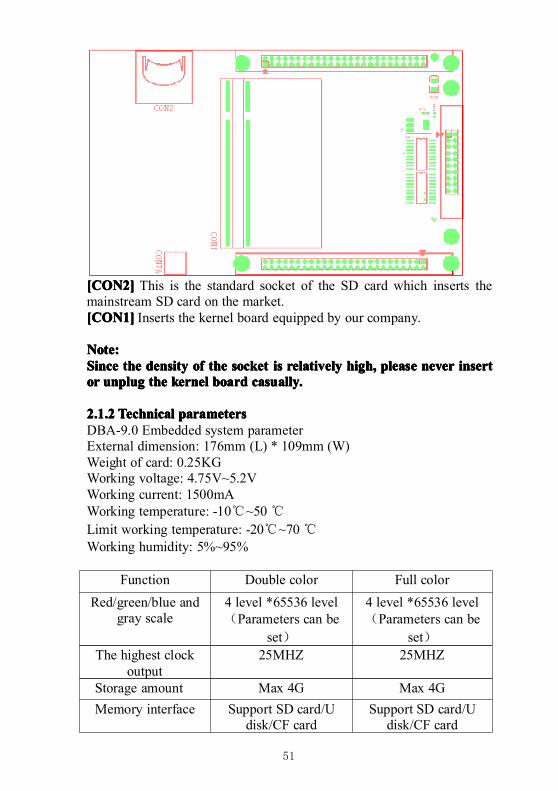
51
[CON2][CON2][CON2][CON2] This is the standard socket of the SD card which inserts themainstream SD card on the market.[CON1][CON1][CON1][CON1] Inserts the kernel board equipped by our company.
Note:Note:Note:Note:SinceSinceSinceSince thethethethe densitydensitydensitydensity ofofofof thethethethe socketsocketsocketsocket isisisis relativelyrelativelyrelativelyrelatively high,high,high,high, pleasepleasepleaseplease nevernevernevernever insertinsertinsertinsertorororor unplugunplugunplugunplug thethethethe kernelkernelkernelkernel boardboardboardboard casually.casually.casually.casually.
2.1.22.1.22.1.22.1.2 TechnicalTechnicalTechnicalTechnical parametersparametersparametersparametersDBA-9.0 Embedded system parameterExternal dimension: 176mm (L) * 109mm (W)Weight of card: 0.25KGWorking voltage: 4.75V~5.2VWorking current: 1500mAWorking temperature: -10℃~50℃Limit working temperature: -20℃~70℃Working humidity: 5%~95%
Function Double color Full color
Red/green/blue andgray scale
4 level *65536 level(Parameters can be
set)
4 level *65536 level(Parameters can be
set)The highest clock
output25MHZ 25MHZ
Storage amount Max 4G Max 4GMemory interface Support SD card/U
disk/CF cardSupport SD card/U
disk/CF card
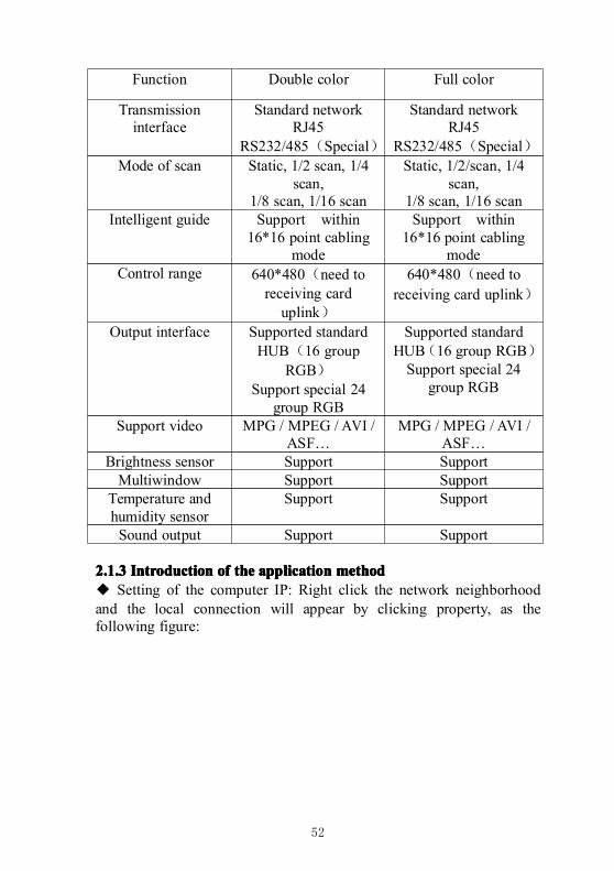
52
Function Double color Full color
Transmissioninterface
Standard networkRJ45
RS232/485(Special)
Standard networkRJ45
RS232/485(Special)Mode of scan Static, 1/2 scan, 1/4
scan,1/8 scan, 1/16 scan
Static, 1/2/scan, 1/4scan,
1/8 scan, 1/16 scanIntelligent guide Support within
16*16 point cablingmode
Support within16*16 point cabling
modeControl range 640*480(need to
receiving carduplink)
640*480(need toreceiving card uplink)
Output interface Supported standardHUB(16 group
RGB)Support special 24
group RGB
Supported standardHUB(16 group RGB)Support special 24
group RGB
Support video MPG / MPEG / AVI /ASF…
MPG / MPEG / AVI /ASF…
Brightness sensor Support SupportMultiwindow Support Support
Temperature andhumidity sensor
Support Support
Sound output Support Support
2.1.32.1.32.1.32.1.3 IntroductionIntroductionIntroductionIntroduction ofofofof thethethethe applicationapplicationapplicationapplication methodmethodmethodmethod◆ Setting of the computer IP: Right click the network neighborhoodand the local connection will appear by clicking property, as thefollowing figure:
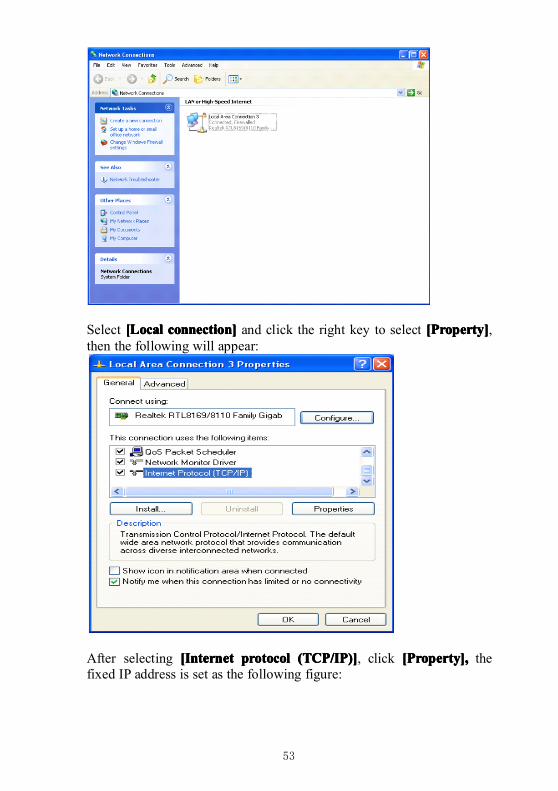
53
Select [[[[LLLLocalocalocalocal connection]connection]connection]connection] and click the right key to select [[[[PPPProperty]roperty]roperty]roperty],then the following will appear:
After selecting [Internet[Internet[Internet[Internet protocolprotocolprotocolprotocol (TCP/IP)(TCP/IP)(TCP/IP)(TCP/IP)]]]], click [[[[PPPProperty]roperty]roperty]roperty],,,, thefixed IP address is set as the following figure:
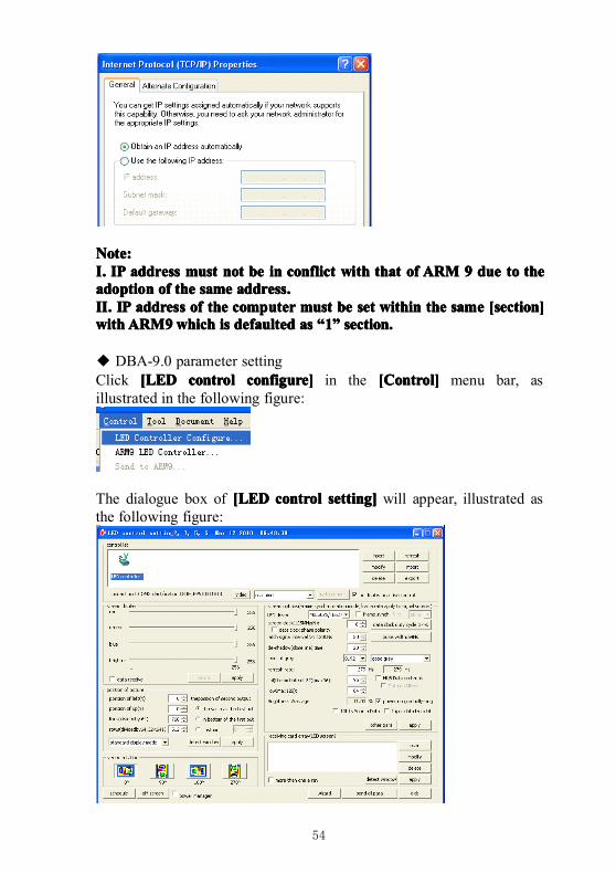
54
Note:Note:Note:Note:IIII.... IPIPIPIP addressaddressaddressaddress mustmustmustmust notnotnotnot bebebebe inininin conflictconflictconflictconflict withwithwithwith thatthatthatthat ofofofof ARMARMARMARM 9999 duedueduedue totototo thethethetheadoptionadoptionadoptionadoption ofofofof thethethethe samesamesamesame address.address.address.address.IIIIIIII.... IPIPIPIP addressaddressaddressaddress ofofofof thethethethe computercomputercomputercomputer mustmustmustmust bebebebe setsetsetset withinwithinwithinwithin thethethethe samesamesamesame [section][section][section][section]withwithwithwithARM9ARM9ARM9ARM9whichwhichwhichwhich isisisis defaulteddefaulteddefaulteddefaulted asasasas ““““1111”””” section.section.section.section.
◆ DBA-9.0 parameter settingClick [LED[LED[LED[LED controlcontrolcontrolcontrol configure]configure]configure]configure] in the [[[[CCCControl]ontrol]ontrol]ontrol] menu bar, asillustrated in the following figure:
The dialogue box of [LED[LED[LED[LED controlcontrolcontrolcontrol setting]setting]setting]setting] will appear, illustrated asthe following figure:
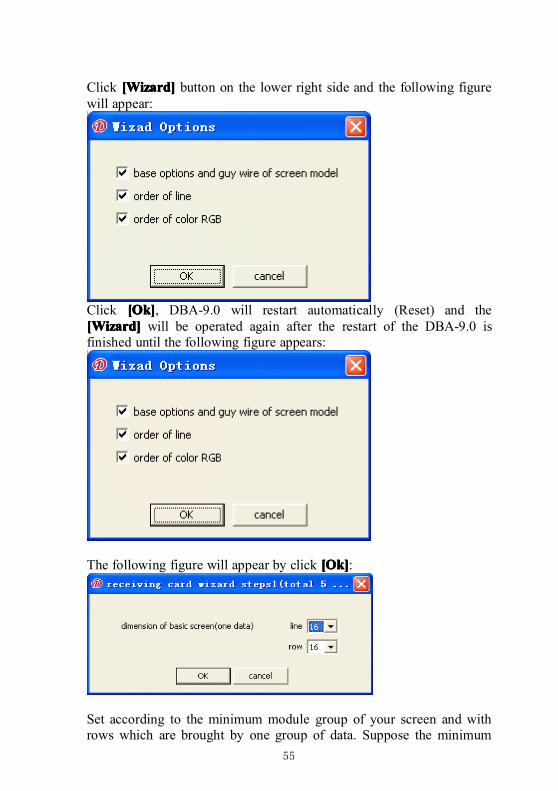
55
Click [[[[WWWWizard]izard]izard]izard] button on the lower right side and the following figurewill appear:
Click [[[[OOOOk]k]k]k], DBA-9.0 will restart automatically (Reset) and the[[[[WWWWizard]izard]izard]izard] will be operated again after the restart of the DBA-9.0 isfinished until the following figure appears:
The following figure will appear by click [[[[OOOOk]k]k]k]:
Set according to the minimum module group of your screen and withrows which are brought by one group of data. Suppose the minimum
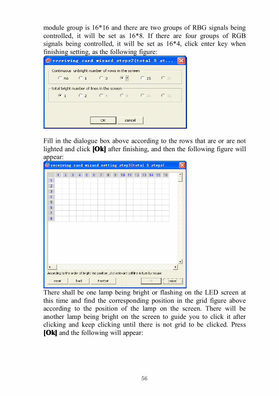
56
module group is 16*16 and there are two groups of RBG signals beingcontrolled, it will be set as 16*8. If there are four groups of RGBsignals being controlled, it will be set as 16*4, click enter key whenfinishing setting, as the following figure:
Fill in the dialogue box above according to the rows that are or are notlighted and click [[[[OOOOk]k]k]k] after finishing, and then the following figure willappear:
There shall be one lamp being bright or flashing on the LED screen atthis time and find the corresponding position in the grid figure aboveaccording to the position of the lamp on the screen. There will beanother lamp being bright on the screen to guide you to click it afterclicking and keep clicking until there is not grid to be clicked. Press[[[[OOOOk]k]k]k] and the following will appear:
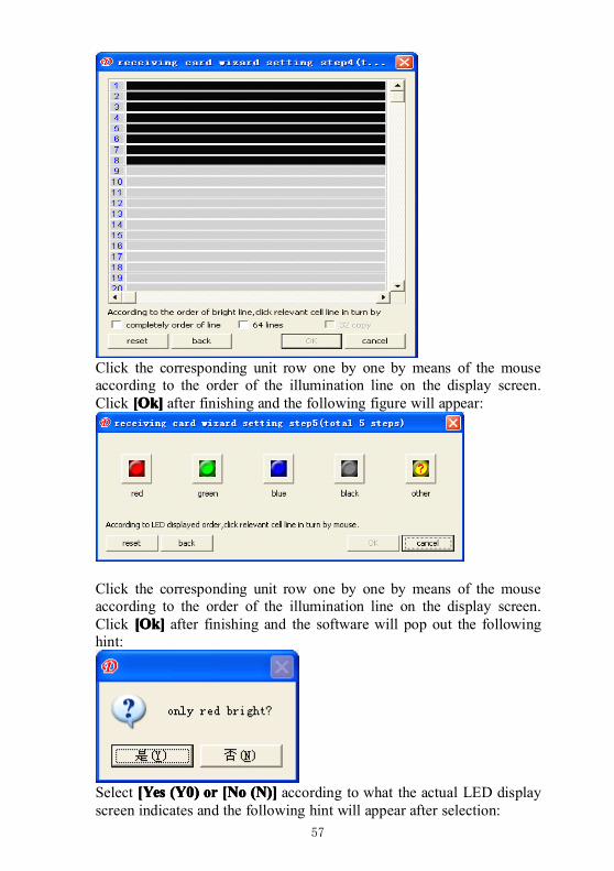
57
Click the corresponding unit row one by one by means of the mouseaccording to the order of the illumination line on the display screen.Click [[[[OOOOk]k]k]k] after finishing and the following figure will appear:
Click the corresponding unit row one by one by means of the mouseaccording to the order of the illumination line on the display screen.Click [[[[OOOOk]k]k]k] after finishing and the software will pop out the followinghint:
Select [Yes[Yes[Yes[Yes (Y0)(Y0)(Y0)(Y0) orororor [No[No[No[No (N)](N)](N)](N)] according to what the actual LED displayscreen indicates and the following hint will appear after selection:
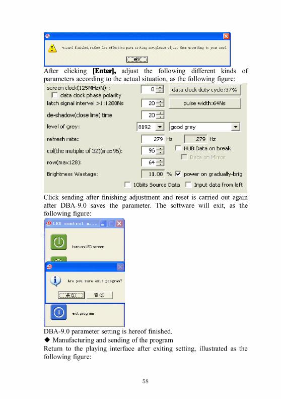
58
After clicking [[[[EEEEnter],nter],nter],nter], adjust the following different kinds ofparameters according to the actual situation, as the following figure:
Click sending after finishing adjustment and reset is carried out againafter DBA-9.0 saves the parameter. The software will exit, as thefollowing figure:
DBA-9.0 parameter setting is hereof finished.◆ Manufacturing and sending of the programReturn to the playing interface after exiting setting, illustrated as thefollowing figure:
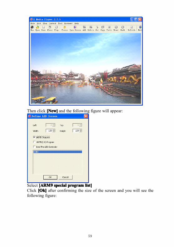
59
Then click [[[[NNNNew]ew]ew]ew] and the following figure will appear:
Select [ARM9[ARM9[ARM9[ARM9 specialspecialspecialspecial programprogramprogramprogram list]list]list]list]Click [[[[OOOOk]k]k]k] after confirming the size of the screen and you will see thefollowing figure:
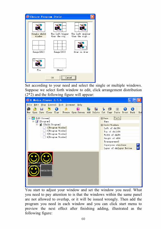
60
Set according to your need and select the single or multiple windows.Suppose we select forth window to edit, click arrangement distribution(2*2) and the following figure will appear:
You start to adjust your window and set the window you need. Whatyou need to pay attention to is that the windows within the same panelare not allowed to overlap, or it will be issued wrongly. Then add theprogram you need in each window and you can click start menu topreview the next effect after finishing adding, illustrated as thefollowing figure:
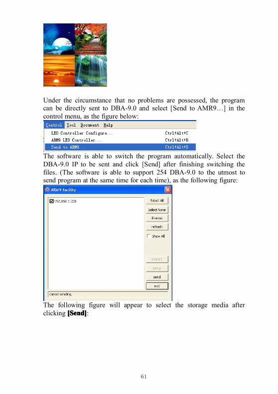
61
Under the circumstance that no problems are possessed, the programcan be directly sent to DBA-9.0 and select [Send to AMR9…] in thecontrol menu, as the figure below:
The software is able to switch the program automatically. Select theDBA-9.0 IP to be sent and click [Send] after finishing switching thefiles. (The software is able to support 254 DBA-9.0 to the utmost tosend program at the same time for each time), as the following figure:
The following figure will appear to select the storage media afterclicking [[[[SSSSend]end]end]end]:
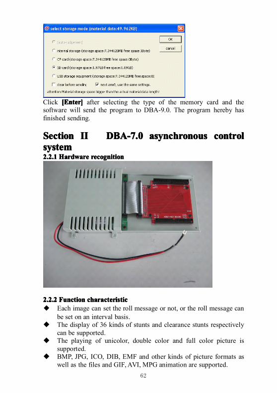
62
Click [[[[EEEEnter]nter]nter]nter] after selecting the type of the memory card and thesoftware will send the program to DBA-9.0. The program hereby hasfinished sending.
SectionSectionSectionSection IIIIIIII DBA-7.0DBA-7.0DBA-7.0DBA-7.0 asynchronousasynchronousasynchronousasynchronous controlcontrolcontrolcontrolsystemsystemsystemsystem2.2.12.2.12.2.12.2.1 HardwareHardwareHardwareHardware recognitionrecognitionrecognitionrecognition
2.2.22.2.22.2.22.2.2 FunctionFunctionFunctionFunction characteristiccharacteristiccharacteristiccharacteristic◆ Each image can set the roll message or not, or the roll message can
be set on an interval basis.� The display of 36 kinds of stunts and clearance stunts respectively
can be supported.� The playing of unicolor, double color and full color picture is
supported.� BMP, JPG, ICO, DIB, EMF and other kinds of picture formats as
well as the files and GIF,AVI, MPG animation are supported.
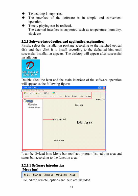
63
� Text editing is supported.� The interface of the software is in simple and convenient
operation.� Timely playing can be realized.
The external interface is supported such as temperature, humidity,clock etc.
2.2.32.2.32.2.32.2.3 SoftwareSoftwareSoftwareSoftware introductionintroductionintroductionintroduction andandandand applicationapplicationapplicationapplication explanationexplanationexplanationexplanationFirstly, select the installation package according to the matched opticaldisk and then click it to install according to the defaulted hint untilsuccessful installation appears. The desktop will appear after successfulinstallation
Double click the icon and the main interface of the software operationwill appear as the following figure:
It can be divided into: Menu bar, tool bar, program list, edition area andstatus bar according to the function area.
2.2.3.12.2.3.12.2.3.12.2.3.1 SoftwareSoftwareSoftwareSoftware introductionintroductionintroductionintroduction[Menu[Menu[Menu[Menu bar]bar]bar]bar]
File, editor, remote, options and help are included.
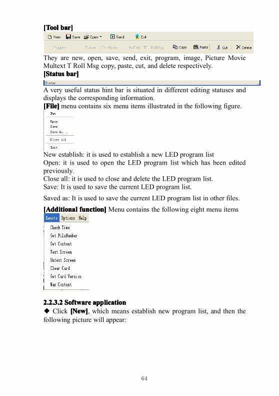
64
[Tool[Tool[Tool[Tool bar]bar]bar]bar]
They are new, open, save, send, exit, program, image, Picture MovieMultext T Roll Msg copy, paste, cut, and delete respectively.[Status[Status[Status[Status bar]bar]bar]bar]
A very useful status hint bar is situated in different editing statuses anddisplays the corresponding information.[File][File][File][File]menu contains six menu items illustrated in the following figure.
New establish: it is used to establish a new LED program listOpen: it is used to open the LED program list which has been editedpreviously.Close all: it is used to close and delete the LED program list.Save: It is used to save the current LED program list.
Saved as: It is used to save the current LED program list in other files.
[Additional[Additional[Additional[Additional function]function]function]function]Menu contains the following eight menu items
2.2.3.22.2.3.22.2.3.22.2.3.2 SoftwareSoftwareSoftwareSoftware applicationapplicationapplicationapplication◆ Click [[[[NNNNew]ew]ew]ew], which means establish new program list, and then thefollowing picture will appear:
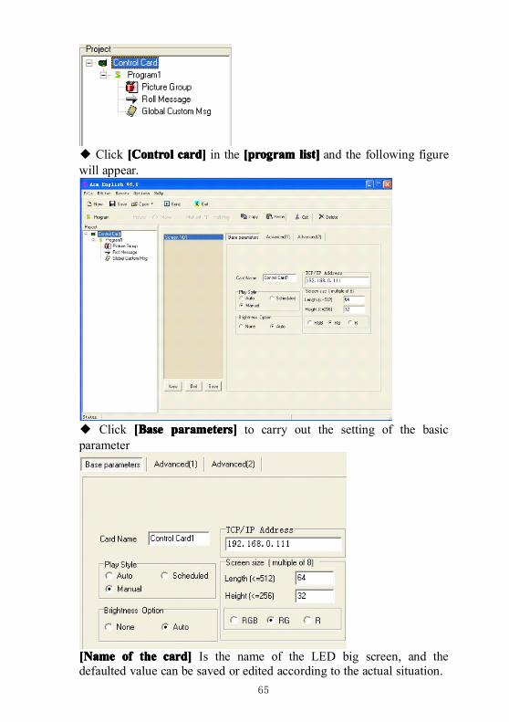
65
◆ Click [[[[CCCControlontrolontrolontrol card]card]card]card] in the [program[program[program[program list]list]list]list] and the following figurewill appear.
◆ Click [[[[BBBBaseaseasease parameters]parameters]parameters]parameters] to carry out the setting of the basicparameter
[Name[Name[Name[Name ofofofof thethethethe card]card]card]card] Is the name of the LED big screen, and thedefaulted value can be saved or edited according to the actual situation.
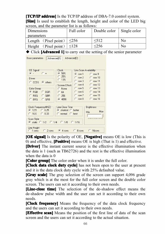
66
[TCP/IP[TCP/IP[TCP/IP[TCP/IP address]address]address]address] Is the TCP/IP address of DBA-7.0 control system.[Size][Size][Size][Size] Is used to establish the length, height and color of the LED bigscreen, and the parameter list is as follows:Dimensionsparameters
Full color Double color Single color
Length (Pixel point) ≤256 ≤512 NoHeight (Pixel point) ≤128 ≤256 No
◆ Click [[[[AAAAdvanceddvanceddvanceddvanced 1]1]1]1] to carry out the setting of the senior parameter
[OE[OE[OE[OE signal]signal]signal]signal] Is the polarity of OE, [[[[NNNNegative]egative]egative]egative] means OE is low (This is0) and effective, [[[[PPPPositive]ositive]ositive]ositive]means OE is high (That is 1) and effective.[Driver][Driver][Driver][Driver] The instant current source is the effective illumination whenthe data is 1 (such as TB62726) and the rest is the effective illuminationwhen the data is 0[Color[Color[Color[Color group]group]group]group] The color order when it is under the full color.[Clock[Clock[Clock[Clock datadatadatadata clockclockclockclock dutydutydutyduty cycle]cycle]cycle]cycle] has not been open to the user at presentand it is the data clock duty cycle with 25% defaulted value.[Gray[Gray[Gray[Gray scale]scale]scale]scale] The gray selection of the screen can support 4,096 gradegray which is at the most for the full color screen and the double colorscreen. The users can set it according to their own needs.[[[[LLLLine-closeine-closeine-closeine-close time]time]time]time] The selection of the de-shadow effect means thede-shadow pulse width and the user can set it according to their ownneeds.[Clock[Clock[Clock[Clock frequency]frequency]frequency]frequency] Means the frequency of the data clock frequencyand the users can set it according to their own needs.[Effective[Effective[Effective[Effective scan]scan]scan]scan] Means the position of the first line of data of the scanscreen and the users can set it according to the actual situation.
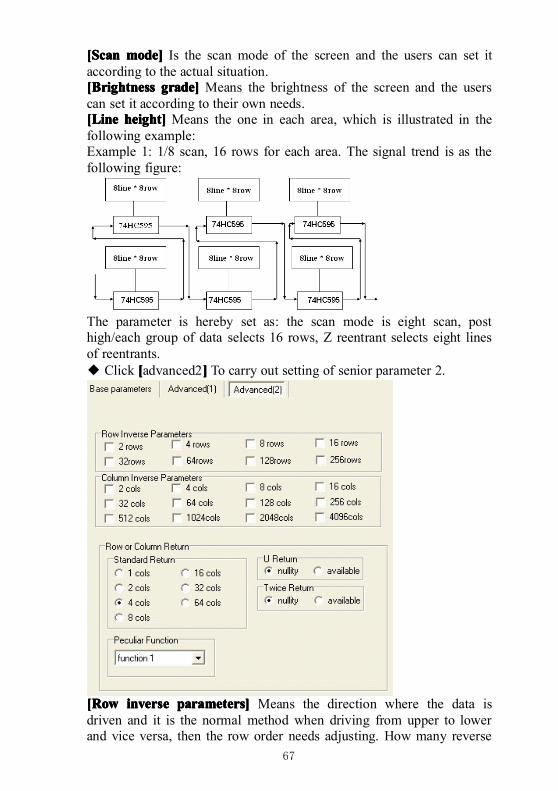
67
[Scan[Scan[Scan[Scan mode]mode]mode]mode] Is the scan mode of the screen and the users can set itaccording to the actual situation.[Brightness[Brightness[Brightness[Brightness grade]grade]grade]grade] Means the brightness of the screen and the userscan set it according to their own needs.[Line[Line[Line[Line height]height]height]height] Means the one in each area, which is illustrated in thefollowing example:Example 1: 1/8 scan, 16 rows for each area. The signal trend is as thefollowing figure:
The parameter is hereby set as: the scan mode is eight scan, posthigh/each group of data selects 16 rows, Z reentrant selects eight linesof reentrants.◆ Click [[[[advanced2]]]] To carry out setting of senior parameter 2.
[Row[Row[Row[Row inverseinverseinverseinverse parameters]parameters]parameters]parameters] Means the direction where the data isdriven and it is the normal method when driving from upper to lowerand vice versa, then the row order needs adjusting. How many reverse
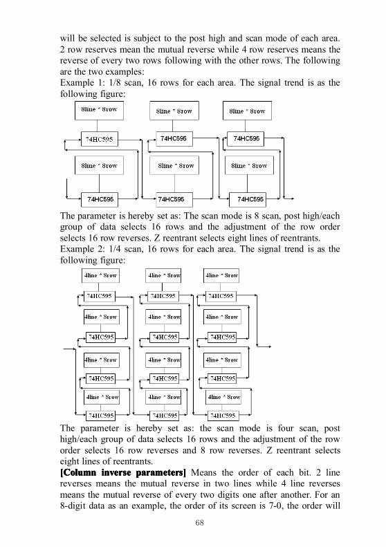
68
will be selected is subject to the post high and scan mode of each area.2 row reserves mean the mutual reverse while 4 row reserves means thereverse of every two rows following with the other rows. The followingare the two examples:Example 1: 1/8 scan, 16 rows for each area. The signal trend is as thefollowing figure:
The parameter is hereby set as: The scan mode is 8 scan, post high/eachgroup of data selects 16 rows and the adjustment of the row orderselects 16 row reverses. Z reentrant selects eight lines of reentrants.Example 2: 1/4 scan, 16 rows for each area. The signal trend is as thefollowing figure:
The parameter is hereby set as: the scan mode is four scan, posthigh/each group of data selects 16 rows and the adjustment of the roworder selects 16 row reverses and 8 row reverses. Z reentrant selectseight lines of reentrants.[Column[Column[Column[Column inverseinverseinverseinverse parameters]parameters]parameters]parameters] Means the order of each bit. 2 linereverses means the mutual reverse in two lines while 4 line reversesmeans the mutual reverse of every two digits one after another. For an8-digit data as an example, the order of its screen is 7-0, the order will
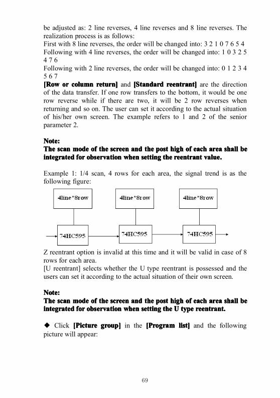
69
be adjusted as: 2 line reverses, 4 line reverses and 8 line reverses. Therealization process is as follows:First with 8 line reverses, the order will be changed into: 3 2 1 0 7 6 5 4Following with 4 line reverses, the order will be changed into: 1 0 3 2 54 7 6Following with 2 line reverses, the order will be changed into: 0 1 2 3 45 6 7[Row[Row[Row[Row orororor columncolumncolumncolumn return]return]return]return] and [[[[SSSStandardtandardtandardtandard reentrant]reentrant]reentrant]reentrant] are the directionof the data transfer. If one row transfers to the bottom, it would be onerow reverse while if there are two, it will be 2 row reverses whenreturning and so on. The user can set it according to the actual situationof his/her own screen. The example refers to 1 and 2 of the seniorparameter 2.
Note:Note:Note:Note:TheTheTheThe scanscanscanscan modemodemodemode ofofofof thethethethe screenscreenscreenscreen andandandand thethethethe postpostpostpost highhighhighhigh ofofofof eacheacheacheach areaareaareaarea shallshallshallshall bebebebeintegratedintegratedintegratedintegrated forforforfor observationobservationobservationobservation whenwhenwhenwhen settingsettingsettingsetting thethethethe reentrantreentrantreentrantreentrant valuevaluevaluevalue....
Example 1: 1/4 scan, 4 rows for each area, the signal trend is as thefollowing figure:
Z reentrant option is invalid at this time and it will be valid in case of 8rows for each area.[U reentrant] selects whether the U type reentrant is possessed and theusers can set it according to the actual situation of their own screen.
Note:Note:Note:Note:TheTheTheThe scanscanscanscan modemodemodemode ofofofof thethethethe screenscreenscreenscreen andandandand thethethethe postpostpostpost highhighhighhigh ofofofof eacheacheacheach areaareaareaarea shallshallshallshall bebebebeintegratedintegratedintegratedintegrated forforforfor observationobservationobservationobservation whenwhenwhenwhen settingsettingsettingsetting thethethethe UUUU typetypetypetype reentrant.reentrant.reentrant.reentrant.
◆ Click [[[[PPPPictureictureictureicture group]group]group]group] in the [[[[PPPProgramrogramrogramrogram list]list]list]list] and the followingpicture will appear:
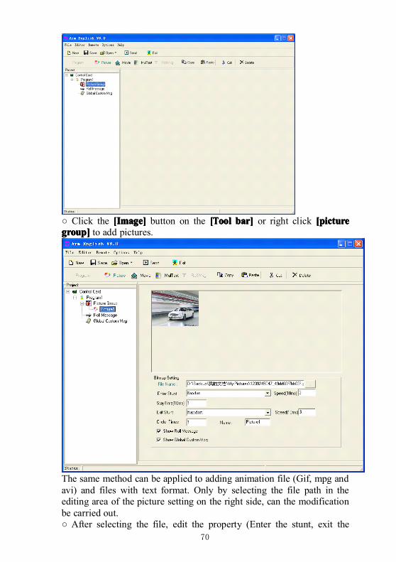
70
○ Click the [[[[IIIImage]mage]mage]mage] button on the [[[[TTTToolooloolool bar]bar]bar]bar] or right click [picture[picture[picture[picturegroup]group]group]group] to add pictures.
The same method can be applied to adding animation file (Gif, mpg andavi) and files with text format. Only by selecting the file path in theediting area of the picture setting on the right side, can the modificationbe carried out.○ After selecting the file, edit the property (Enter the stunt, exit the
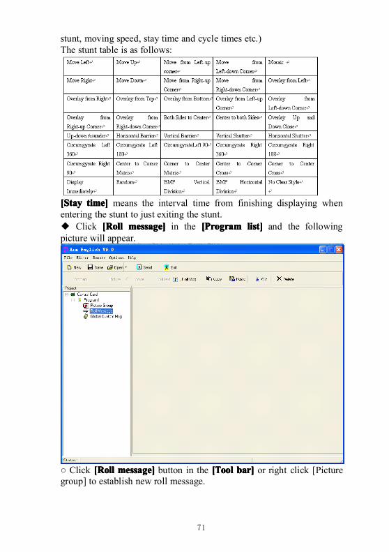
71
stunt, moving speed, stay time and cycle times etc.)The stunt table is as follows:
[[[[SSSStaytaytaytay time]time]time]time] means the interval time from finishing displaying whenentering the stunt to just exiting the stunt.◆ Click [[[[RRRRollollolloll messagemessagemessagemessage]]]] in the [[[[PPPProgramrogramrogramrogram list]list]list]list] and the followingpicture will appear.
○ Click [[[[RRRRollollolloll message]message]message]message] button in the [[[[TTTToolooloolool bar]bar]bar]bar] or right click [Picturegroup] to establish new roll message.
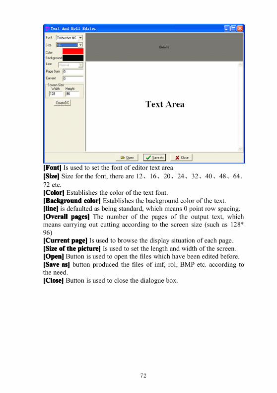
72
[Font][Font][Font][Font] Is used to set the font of editor text area[Size][Size][Size][Size] Size for the font, there are 12、16、20、24、32、40、48、64、72 etc.[Color][Color][Color][Color] Establishes the color of the text font.[Background[Background[Background[Background color]color]color]color] Establishes the background color of the text.[line][line][line][line] is defaulted as being standard, which means 0 point row spacing.[Overall[Overall[Overall[Overall pages]pages]pages]pages] The number of the pages of the output text, whichmeans carrying out cutting according to the screen size (such as 128*96)[Current[Current[Current[Current page]page]page]page] Is used to browse the display situation of each page.[Size[Size[Size[Size ofofofof thethethethe picture]picture]picture]picture] Is used to set the length and width of the screen.[Open][Open][Open][Open] Button is used to open the files which have been edited before.[Save[Save[Save[Save as]as]as]as] button produced the files of imf, rol, BMP etc. according tothe need.[Close][Close][Close][Close] Button is used to close the dialogue box.
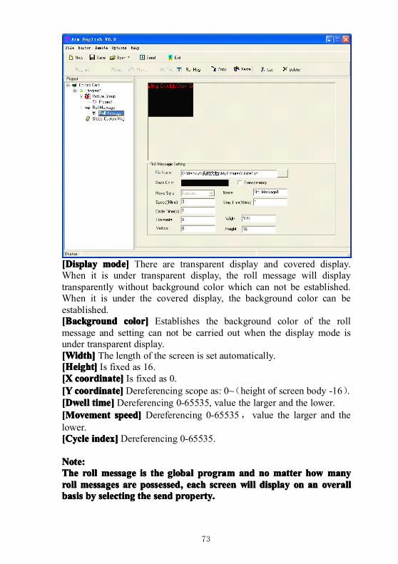
73
[Display[Display[Display[Display mode]mode]mode]mode] There are transparent display and covered display.When it is under transparent display, the roll message will displaytransparently without background color which can not be established.When it is under the covered display, the background color can beestablished.[Background[Background[Background[Background color]color]color]color] Establishes the background color of the rollmessage and setting can not be carried out when the display mode isunder transparent display.[Width][Width][Width][Width] The length of the screen is set automatically.[Height][Height][Height][Height] Is fixed as 16.[X[X[X[X coordinatecoordinatecoordinatecoordinate]]]] Is fixed as 0.[Y[Y[Y[Y coordinatecoordinatecoordinatecoordinate]]]] Dereferencing scope as: 0~(height of screen body -16).[[[[DwellDwellDwellDwell timetimetimetime]]]] Dereferencing 0-65535, value the larger and the lower.[Movement[Movement[Movement[Movement speed]speed]speed]speed] Dereferencing 0-65535,value the larger and thelower.[[[[CycleCycleCycleCycle indexindexindexindex]]]] Dereferencing 0-65535.
Note:Note:Note:Note:TheTheTheThe rollrollrollroll messagemessagemessagemessage isisisis thethethethe globalglobalglobalglobal programprogramprogramprogram andandandand nononono mattermattermattermatter howhowhowhow manymanymanymanyrollrollrollroll messagemessagemessagemessagessss areareareare possessed,possessed,possessed,possessed, eacheacheacheach screenscreenscreenscreen willwillwillwill displaydisplaydisplaydisplay onononon anananan overalloveralloveralloverallbasisbasisbasisbasis bybybyby selectingselectingselectingselecting thethethethe sendsendsendsend property.property.property.property.
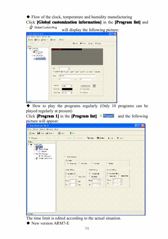
74
◆ Flow of the clock, temperature and humidity manufacturingClick [[[[GGGGloballoballoballobal customizationcustomizationcustomizationcustomization information]information]information]information] in the [[[[PPPProgramrogramrogramrogram list]list]list]list] and
will display the following picture:
◆ How to play the programs regularly (Only 10 programs can beplayed regularly at present)Click [[[[PPPProgramrogramrogramrogram 1]1]1]1] in the [[[[PPPProgramrogramrogramrogram list]list]list]list] and the followingpicture will appear:
The time limit is edited according to the actual situation.◆ New version ARM7-E
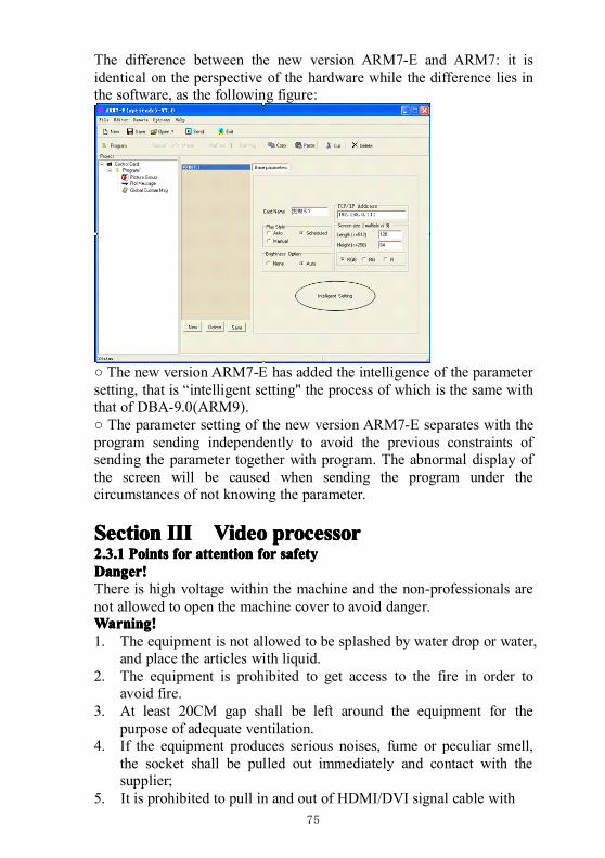
75
The difference between the new version ARM7-E and ARM7: it isidentical on the perspective of the hardware while the difference lies inthe software, as the following figure:
○ The new version ARM7-E has added the intelligence of the parametersetting, that is “intelligent setting" the process of which is the same withthat of DBA-9.0(ARM9).○ The parameter setting of the new version ARM7-E separates with theprogram sending independently to avoid the previous constraints ofsending the parameter together with program. The abnormal display ofthe screen will be caused when sending the program under thecircumstances of not knowing the parameter.
SectionSectionSectionSection IIIIIIIIIIII VideoVideoVideoVideo processorprocessorprocessorprocessor2.3.12.3.12.3.12.3.1 PointsPointsPointsPoints forforforfor attentionattentionattentionattention forforforfor safetysafetysafetysafetyDanger!Danger!Danger!Danger!There is high voltage within the machine and the non-professionals arenot allowed to open the machine cover to avoid danger.Warning!Warning!Warning!Warning!1. The equipment is not allowed to be splashed by water drop or water,
and place the articles with liquid.2. The equipment is prohibited to get access to the fire in order to
avoid fire.3. At least 20CM gap shall be left around the equipment for the
purpose of adequate ventilation.4. If the equipment produces serious noises, fume or peculiar smell,
the socket shall be pulled out immediately and contact with thesupplier;
5. It is prohibited to pull in and out of HDMI/DVI signal cable with
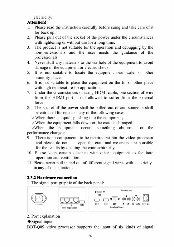
76
electricity.Attention!Attention!Attention!Attention!1. Please read the instruction carefully before suing and take care of it
for back up;2. Please pull out of the socket of the power under the circumstances
with lightening or without use for a long time;3. The product is not suitable for the operation and debugging by the
non-professionals and the user needs the guidance of theprofessionals;
4. Never stuff any materials to the via hole of the equipment to avoiddamage of the equipment or electric shock;
5. It is not suitable to locate the equipment near water or otherhumidity place;
6. It is not suitable to place the equipment on the fin or other placewith high temperature for application;
7. Under the circumstances of using HDMI cable, one section of wirefrom the HDMI port is not allowed to suffer from the externalforce.
8. The socket of the power shall be pulled out of and someone shallbe entrusted for repair in any of the following cases:
○ When there is liquid splashing into the equipment;○ When the equipment falls down or the crate is damaged;○When the equipment occurs something abnormal or the
performance changes;9. There is no components to be repaired within the video processor
and please do not open the crate and we are not responsiblefor the results by opening the crate arbitrarily.
10. Please keep certain distance with other equipment to facilitateoperation and ventilation.
11. Please never pull in and out of different signal wires with electricityin any of the situations.
2.3.22.3.22.3.22.3.2 HardwareHardwareHardwareHardware connectionconnectionconnectionconnection1. The signal port graphic of the back panel:
2. Port explanation◆Signal inputDBT-Q09 video processor supports the input of six kinds of signal
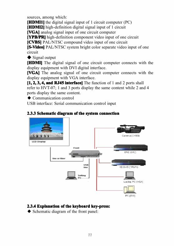
77
sources, among which:[HDMI1][HDMI1][HDMI1][HDMI1] the digital signal input of 1 circuit computer (PC)[HDMI2][HDMI2][HDMI2][HDMI2] high-definition digital signal input of 1 circuit[VGA][VGA][VGA][VGA] analog signal input of one circuit computer[YPB/PR][YPB/PR][YPB/PR][YPB/PR] high-definition component video input of one circuit[CVBS][CVBS][CVBS][CVBS] PAL/NTSC compound video input of one circuit[S-Video][S-Video][S-Video][S-Video] PAL/NTSC system bright color separate video input of onecircuit◆ Signal output[HDMI][HDMI][HDMI][HDMI] The digital signal of one circuit computer connects with thedisplay equipment with DVI digital interface.[VGA][VGA][VGA][VGA] The analog signal of one circuit computer connects with thedisplay equipment with VGA interface.[1,[1,[1,[1, 2,2,2,2, 3,3,3,3, 4,4,4,4, andandandand RJ45RJ45RJ45RJ45 interface]interface]interface]interface] The function of 1 and 2 ports shallrefer to HVT-07; 1 and 3 ports display the same content while 2 and 4ports display the same content.◆ Communication controlUSB interface: Serial communication control input
2.3.32.3.32.3.32.3.3 SchematicSchematicSchematicSchematic diagramdiagramdiagramdiagram ofofofof thethethethe systemsystemsystemsystem connectionconnectionconnectionconnection
2.3.42.3.42.3.42.3.4 ExplanationExplanationExplanationExplanation ofofofof thethethethe keyboardkeyboardkeyboardkeyboard key-press:key-press:key-press:key-press:◆ Schematic diagram of the front panel:
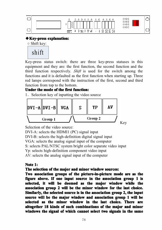
78
◆Key-pressKey-pressKey-pressKey-press explanation:explanation:explanation:explanation:○ Shift key:
shiftKey-press status switch: there are three key-press statuses in thisequipment and they are: the first function, the second function and thethird function respectively. Shift is used for the switch among thefunctions and it is defaulted as the first function when starting up. Threered lamps correspond with the instruction of the first, second and thirdfunction from top to the bottom.UnderUnderUnderUnder thethethethe modemodemodemode ofofofof thethethethe firstfirstfirstfirst function:function:function:function:1.Selection key of inputting the video source
KeySelection of the video source:DVI-A: selects the HDMI1 (PC) signal inputDVI-B: selects the high-definition digital signal inputVGA: selects the analog signal input of the computerS: selects PAL/NTSC system bright color separate video inputYp: selects high-definition component video inputAV: selects the analog signal input of the computer
NoteNoteNoteNote 1:1:1:1:TheTheTheThe selectionselectionselectionselection ofofofof thethethethe majormajormajormajor andandandand minorminorminorminor windowwindowwindowwindow sources:sources:sources:sources:TwoTwoTwoTwo associationassociationassociationassociation groupsgroupsgroupsgroups ofofofof thethethethe picture-in-picturepicture-in-picturepicture-in-picturepicture-in-picture modemodemodemode areareareare asasasas thethethethefigurefigurefigurefigure above.above.above.above. IfIfIfIf oneoneoneone inputinputinputinput sourcesourcesourcesource inininin thethethethe associationassociationassociationassociation groupgroupgroupgroup 1111 isisisisselected,selected,selected,selected, itititit willwillwillwill bebebebe deemeddeemeddeemeddeemed asasasas thethethethe majormajormajormajor windowwindowwindowwindow whilewhilewhilewhile thethethetheassociationassociationassociationassociation groupgroupgroupgroup 2222 willwillwillwill bebebebe thethethethe minorminorminorminor windowwindowwindowwindow forforforfor thethethethe lastlastlastlast choice.choice.choice.choice.Similarly,Similarly,Similarly,Similarly, thethethethe selectedselectedselectedselected sourcesourcesourcesource isisisis inininin thethethethe associationassociationassociationassociation groupgroupgroupgroup 2,2,2,2, thethethethe inputinputinputinputsourcesourcesourcesource willwillwillwill bebebebe thethethethe majormajormajormajor windowwindowwindowwindow andandandand associationassociationassociationassociation groupgroupgroupgroup 1111 willwillwillwill bebebebeselectedselectedselectedselected asasasas thethethethe minorminorminorminor windowwindowwindowwindow inininin thethethethe lastlastlastlast choice.choice.choice.choice. ThereThereThereThere arearearearealtogetheraltogetheraltogetheraltogether 18181818 kindskindskindskinds ofofofof suchsuchsuchsuch combinationscombinationscombinationscombinations ofofofof thethethethe majormajormajormajor andandandand minorminorminorminorwindowswindowswindowswindows thethethethe signalsignalsignalsignal ofofofof whichwhichwhichwhich cannotcannotcannotcannot selectselectselectselect twotwotwotwo signalssignalssignalssignals inininin thethethethe samesamesamesame
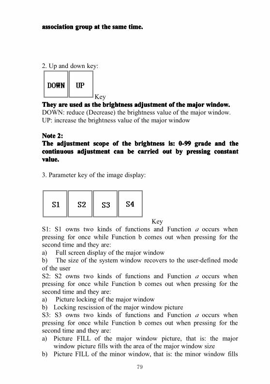
79
associationassociationassociationassociation groupgroupgroupgroup atatatat thethethethe samesamesamesame time.time.time.time.
2. Up and down key:
KeyTheyTheyTheyThey areareareare usedusedusedused asasasas thethethethe brightnessbrightnessbrightnessbrightness adjustmentadjustmentadjustmentadjustment ofofofof thethethethe majormajormajormajor window.window.window.window.DOWN: reduce (Decrease) the brightness value of the major window.UP: increase the brightness value of the major window
NoteNoteNoteNote 2:2:2:2:TheTheTheThe adjustmentadjustmentadjustmentadjustment scopescopescopescope ofofofof thethethethe brightnessbrightnessbrightnessbrightness is:is:is:is: 0-990-990-990-99 gradegradegradegrade andandandand thethethethecontinuouscontinuouscontinuouscontinuous adjustmentadjustmentadjustmentadjustment cancancancan bebebebe carriedcarriedcarriedcarried outoutoutout bybybyby pressingpressingpressingpressing constantconstantconstantconstantvalue.value.value.value.
3. Parameter key of the image display:
KeyS1: S1 owns two kinds of functions and Function a occurs whenpressing for once while Function b comes out when pressing for thesecond time and they are:a) Full screen display of the major windowb) The size of the system window recovers to the user-defined modeof the userS2: S2 owns two kinds of functions and Function a occurs whenpressing for once while Function b comes out when pressing for thesecond time and they are:a) Picture locking of the major windowb) Locking rescission of the major window pictureS3: S3 owns two kinds of functions and Function a occurs whenpressing for once while Function b comes out when pressing for thesecond time and they are:a) Picture FILL of the major window picture, that is: the major
window picture fills with the area of the major window sizeb) Picture FILL of the minor window, that is: the minor window fills
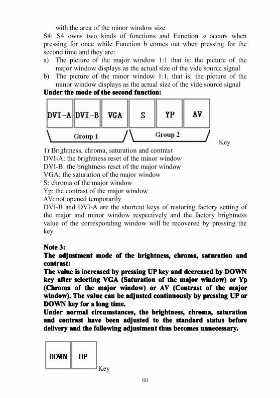
80
with the area of the minor window sizeS4: S4 owns two kinds of functions and Function a occurs whenpressing for once while Function b comes out when pressing for thesecond time and they are:a) The picture of the major window 1:1 that is: the picture of the
major window displays as the actual size of the vide source signalb) The picture of the minor window 1:1, that is: the picture of the
minor window displays as the actual size of the vide source signalUnderUnderUnderUnder thethethethe modemodemodemode ofofofof thethethethe secondsecondsecondsecond function:function:function:function:
Key1) Brightness, chroma, saturation and contrastDVI-A: the brightness reset of the minor windowDVI-B: the brightness reset of the major windowVGA: the saturation of the major windowS: chroma of the major windowYp: the contrast of the major windowAV: not opened temporarilyDVI-B and DVI-A are the shortcut keys of restoring factory setting ofthe major and minor window respectively and the factory brightnessvalue of the corresponding window will be recovered by pressing thekey.
NoteNoteNoteNote 3:3:3:3:TheTheTheThe adjustmentadjustmentadjustmentadjustment modemodemodemode ofofofof thethethethe brightness,brightness,brightness,brightness, chroma,chroma,chroma,chroma, saturationsaturationsaturationsaturation andandandandcontrast:contrast:contrast:contrast:TheTheTheThe valuevaluevaluevalue isisisis increasedincreasedincreasedincreased bybybyby pressingpressingpressingpressing UPUPUPUP keykeykeykey andandandand decreaseddecreaseddecreaseddecreased bybybyby DOWNDOWNDOWNDOWNkeykeykeykey afterafterafterafter selectingselectingselectingselecting VGAVGAVGAVGA ((((SSSSaturationaturationaturationaturation ofofofof thethethethe majormajormajormajor window)window)window)window) orororor YpYpYpYp((((CCCChromahromahromahroma ofofofof thethethethe majormajormajormajor window)window)window)window) orororor AVAVAVAV ((((CCCContrastontrastontrastontrast ofofofof thethethethe majormajormajormajorwindow).window).window).window). TheTheTheThe valuevaluevaluevalue cancancancan bebebebe adjustedadjustedadjustedadjusted continuouslycontinuouslycontinuouslycontinuously bybybyby pressingpressingpressingpressing UPUPUPUP ororororDOWNDOWNDOWNDOWN keykeykeykey forforforfor aaaa longlonglonglong time.time.time.time.UnderUnderUnderUnder normalnormalnormalnormal circumstances,circumstances,circumstances,circumstances, thethethethe brightness,brightness,brightness,brightness, chroma,chroma,chroma,chroma, saturationsaturationsaturationsaturationandandandand contrastcontrastcontrastcontrast havehavehavehave beenbeenbeenbeen adjustedadjustedadjustedadjusted totototo thethethethe standardstandardstandardstandard statusstatusstatusstatus beforebeforebeforebeforedeliverydeliverydeliverydelivery andandandand thethethethe followingfollowingfollowingfollowing adjustmentadjustmentadjustmentadjustment thusthusthusthus becomesbecomesbecomesbecomes unnecessary.unnecessary.unnecessary.unnecessary.
Key
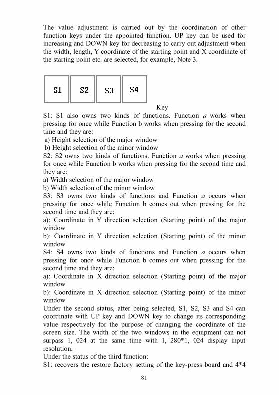
81
The value adjustment is carried out by the coordination of otherfunction keys under the appointed function. UP key can be used forincreasing and DOWN key for decreasing to carry out adjustment whenthe width, length, Y coordinate of the starting point and X coordinate ofthe starting point etc. are selected, for example, Note 3.
KeyS1: S1 also owns two kinds of functions. Function a works whenpressing for once while Function b works when pressing for the secondtime and they are:a) Height selection of the major windowb) Height selection of the minor windowS2: S2 owns two kinds of functions. Function a works when pressingfor once while Function b works when pressing for the second time andthey are:a) Width selection of the major windowb) Width selection of the minor windowS3: S3 owns two kinds of functions and Function a occurs whenpressing for once while Function b comes out when pressing for thesecond time and they are:a): Coordinate in Y direction selection (Starting point) of the majorwindowb): Coordinate in Y direction selection (Starting point) of the minorwindowS4: S4 owns two kinds of functions and Function a occurs whenpressing for once while Function b comes out when pressing for thesecond time and they are:a): Coordinate in X direction selection (Starting point) of the majorwindowb): Coordinate in X direction selection (Starting point) of the minorwindowUnder the second status, after being selected, S1, S2, S3 and S4 cancoordinate with UP key and DOWN key to change its correspondingvalue respectively for the purpose of changing the coordinate of thescreen size. The width of the two windows in the equipment can notsurpass 1, 024 at the same time with 1, 280*1, 024 display inputresolution.Under the status of the third function:S1: recovers the restore factory setting of the key-press board and 4*4
82
matrix red lamp will flash for 7 times and the reset is finished bypressing S1 key for more than 10 seconds. The system needs poweringup after resetting the system.S2: recovers the reset of the video system.
Note:Note:Note:Note:WhenWhenWhenWhen thethethethe adjustmentadjustmentadjustmentadjustment datadatadatadata isisisis lostlostlostlost orororor inininin disorderdisorderdisorderdisorder forforforfor thethethethe reasonsreasonsreasonsreasonsunknown,unknown,unknown,unknown, resultingresultingresultingresulting inininin thethethethe failurefailurefailurefailure totototo normallynormallynormallynormally displaydisplaydisplaydisplay thethethethe imageimageimageimage ofofofofthethethethe system,system,system,system, youyouyouyou cancancancan recoverrecoverrecoverrecover thethethethe datadatadatadata whenwhenwhenwhen deliverydeliverydeliverydelivery bybybyby meansmeansmeansmeans ofofofofinitializationinitializationinitializationinitialization operationoperationoperationoperation andandandand thenthenthenthen adjustadjustadjustadjust accordingaccordingaccordingaccording totototo thethethethe settingsettingsettingsettingexplanationexplanationexplanationexplanation above.above.above.above.
2.3.52.3.52.3.52.3.5 OperationOperationOperationOperation casecasecasecaseOperationOperationOperationOperation casecasecasecase
Connect the peripheral equipment including input source (6 circuits atleast connects one circuit of source and HDMI interface connects thecomputer by opening [Copy mode],) (The case takes computer sourceHDMI 1 port and AV two circuits channel as an example), outputsource USB.1. Open DBT-Q2009 power and it is defaulted as the first status whenstarting up. Press HDMI1 on the panel and observe whether there aresome changes (controlled) NOT1 on the image of the LED screen or[Output external display] and press S3 key for twice.2. Press [SHIFT] key for once to come into [Status of the secondfunction] (the small liquid crystal display on the right can be seen or thesecond lamp of the red lamp indication will be bright)� Press the liquid crystal on the right side of S3 [Y starting point of themajor window] and there will be Y value displayed. “UP” can be usedfor increasing the value of the coordinate while [DOWN] key fordecreasing the value of the coordinate with the defaulted value “0”.� Press S3 [Y starting point of the minor window] again, the Y startingpoint of the minor window is adjusted by the coordination of “UP” and“DOWN” key.Similarly, S1, S2 or S4 coordinate with “UP” and “DOWN” key toadjust the size and coordinate of the corresponding windowsrespectively; press “DVI-A” or “DVI-B” or “VGA”, “S” or “YP” or“UP” and “DOWN” key can also be used to adjust the setting of thecontrast, saturation and other parameters of the corresponding majorwindow. (The specific function under the second status refers to thefunction explanation of “under the mode of the second function”)1. [SHIFT] Key is used to enter “the first function mode” and pressS3, “FILL” S4 “1:1” for adjustment. Pressing once means the majorwindow while the minor window will come out by pressing for the
83
second time.2. The switch of HDMI1 and AV between the major and minorwindows can be conducted by finishing the 3 procedures above. Themajor window will display the content of AV by pressing AV while theminor window displays the content of HDMI1. When pressing theHDMI1 content that the HDMI1 major window displays, the minorwindow will display the content of AV. In this way, the switch of 2circuit source can be realized. If there is the switch of the source ofmore circuit, we only need to select the corresponding channel first andthen adopt S3 and S4 to set the corresponding channel as “FILL” or“1:1”. When we setting the parameter of the “corresponding channel”,there must have video input on that (the content of the channel shall beoutput), only in this way, can the parameter issued respond.3.NOTE:NOTE:NOTE:NOTE: IIIIffff thethethethe outputoutputoutputoutput externalexternalexternalexternal displaydisplaydisplaydisplay isisisis connected,connected,connected,connected, wewewewe cancancancan makemakemakemake aaaajudgmentjudgmentjudgmentjudgment onononon whetherwhetherwhetherwhether thethethethe equipmentequipmentequipmentequipment isisisis underunderunderunder controlcontrolcontrolcontrol bybybyby observingobservingobservingobservingwhetherwhetherwhetherwhether thethethethe contentcontentcontentcontent ofofofof thethethethe displaydisplaydisplaydisplay hashashashas changedchangedchangedchanged orororor not.not.not.not. IfIfIfIf thethethetheexternalexternalexternalexternal displaydisplaydisplaydisplay isisisis notnotnotnot connected,connected,connected,connected, wewewewe cancancancan carrycarrycarrycarry outoutoutout judgmentjudgmentjudgmentjudgment bybybybymeansmeansmeansmeans ofofofof LEDLEDLEDLED electronicelectronicelectronicelectronic screen.screen.screen.screen.
a. Black screen of the electronic screen1. Under the normal circumstances, the output yellow lamp of RJ45port of the receiving card is connected, the green lamp will be brightalways. On condition that the yellow is bright while the green one is not,it means that the receiving card has been connected with the lack ofdata, please confirm the connection of the video source and HDMIneeds to open the copy mode.2. The data flash of the receiving card is still in black screen and inspectwhether the parameter of the receiving card is correct; the too smallscreen displays that the position coordinate has deviated and inspectwhether the resolution of the display card is 1, 280*1, 024 or not. Orpress S3 under the mode of the first function and press S1 to seewhether there has displayed or not. The setting and adjustment can becarried out by the coordination of the software according to theexplanation when there is display.3. Inspect whether the source channel is selected correctly and whetherwhat has been played is DVD. Some videos own the black edge on theupper and lower side.4. Please contact with us if there is still something unclear.b. The picture of the window is not clearPlease inspect the resolution of the computer and 1, 028* 1, 024 modeis entailed.

84
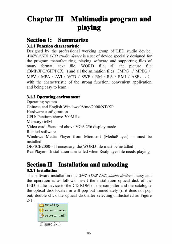
85
ChapterChapterChapterChapter IIIIIIIIIIII MultimediaMultimediaMultimediaMultimedia pppprogramrogramrogramrogram andandandandpppplayinglayinglayinglaying
SectionSectionSectionSection I:I:I:I: SummarizeSummarizeSummarizeSummarize3.1.13.1.13.1.13.1.1 FunctionFunctionFunctionFunction characteristiccharacteristiccharacteristiccharacteristicDesigned by the professional working group of LED studio device,XMPLAYER LED studio device is a set of device specially designed forthe program manufacturing, playing software and supporting files ofmany format: text file, WORD file, all the picture file(BMP/JPG/GIF/PCX...) and all the animation files (MPG /MPEG/MPV/MPA/AVI/VCD/SWF/RM/RA/RMJ/ASF...)with the characteristic of the strong function, convenient applicationand being easy to learn.
3.1.23.1.23.1.23.1.2 OperatingOperatingOperatingOperating environmentenvironmentenvironmentenvironmentOperating systemChinese and English Windows98/me/2000/NT/XPHardware configurationCPU: Pentium above 300MHzMemory: 64MVideo card: Standard above VGA 256 display modeRelated softwareWindows Media Player from Microsoft (MediaPlayer) -- must beinstalledOFFICE2000-- If necessary, the WORD file must be installedRealPlayer---Installation is entailed when Realplayer file needs playing
SectionSectionSectionSection IIIIIIII InstallationInstallationInstallationInstallation andandandand unloadingunloadingunloadingunloading3.2.13.2.13.2.13.2.1 InstallationInstallationInstallationInstallationThe software installation of XMPLAYER LED studio device is easy andthe operation is as follows: insert the installation optical disk of theLED studio device to the CD-ROM of the computer and the cataloguethe optical disk locates in will pop out immediately (if it does not popout, double click the optical disk after selecting), illustrated as Figure2-1.
(Figure 2-1)
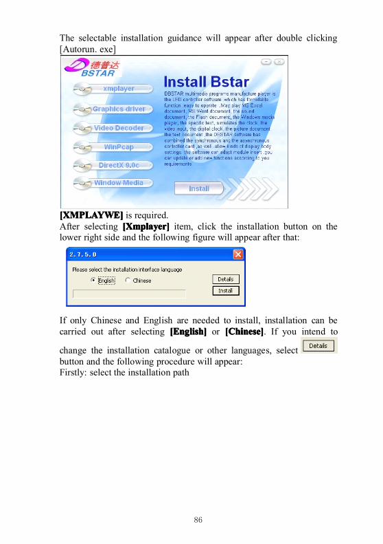
86
The selectable installation guidance will appear after double clicking[Autorun. exe]
[XMPLAYWE[XMPLAYWE[XMPLAYWE[XMPLAYWE]]]] is required.After selecting [[[[XXXXmplayer]mplayer]mplayer]mplayer] item, click the installation button on thelower right side and the following figure will appear after that:
If only Chinese and English are needed to install, installation can becarried out after selecting [English][English][English][English] or [Chinese][Chinese][Chinese][Chinese]. If you intend to
change the installation catalogue or other languages, selectbutton and the following procedure will appear:Firstly: select the installation path
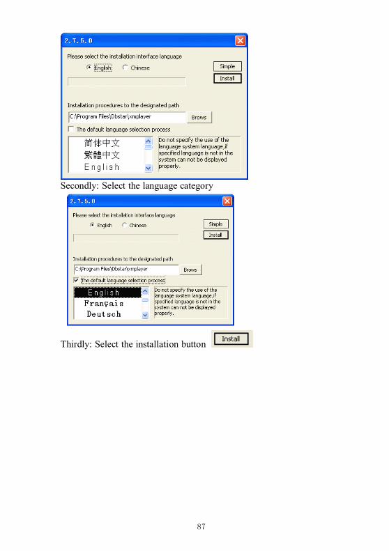
87
Secondly: Select the language category
Thirdly: Select the installation button
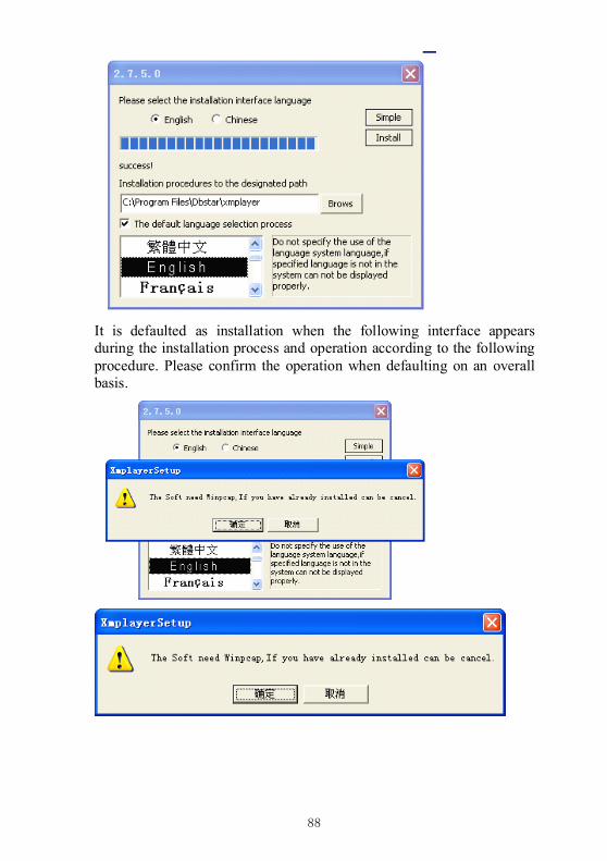
88
It is defaulted as installation when the following interface appearsduring the installation process and operation according to the followingprocedure. Please confirm the operation when defaulting on an overallbasis.
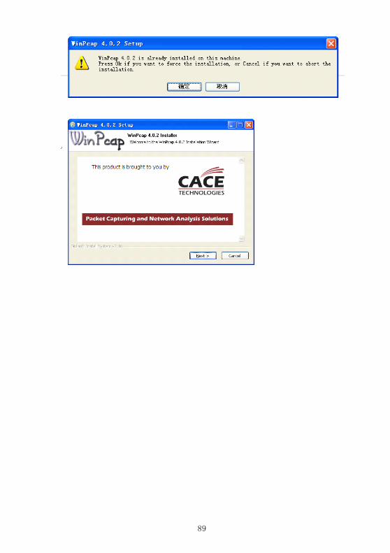
89
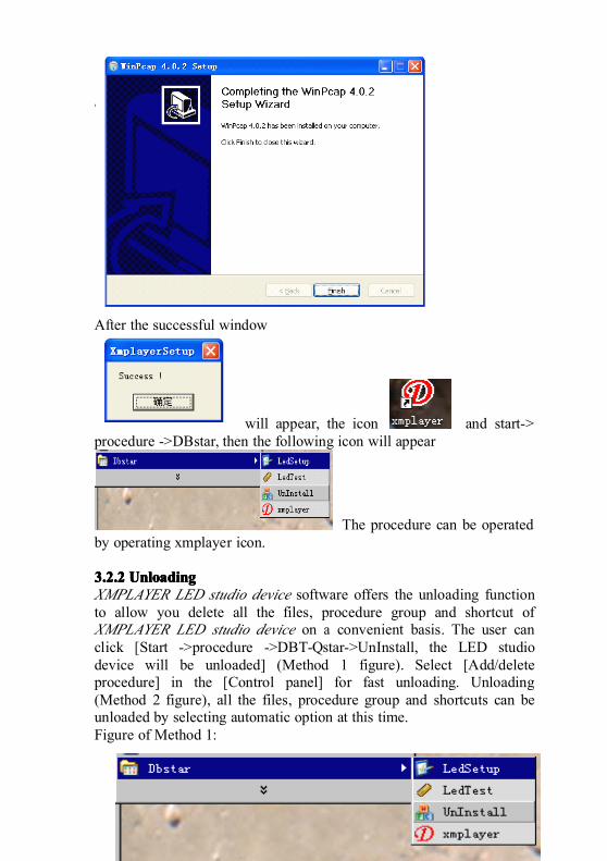
90
After the successful window
will appear, the icon and start->procedure ->DBstar, then the following icon will appear
The procedure can be operatedby operating xmplayer icon.
3.2.23.2.23.2.23.2.2 UnloadingUnloadingUnloadingUnloadingXMPLAYER LED studio device software offers the unloading functionto allow you delete all the files, procedure group and shortcut ofXMPLAYER LED studio device on a convenient basis. The user canclick [Start ->procedure ->DBT-Qstar->UnInstall, the LED studiodevice will be unloaded] (Method 1 figure). Select [Add/deleteprocedure] in the [Control panel] for fast unloading. Unloading(Method 2 figure), all the files, procedure group and shortcuts can beunloaded by selecting automatic option at this time.Figure of Method 1:
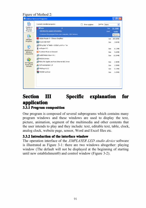
91
Figure of Method 2:
SectionSectionSectionSection IIIIIIIIIIII SpecificSpecificSpecificSpecific explanationexplanationexplanationexplanation forforforforapplicationapplicationapplicationapplication3.3.13.3.13.3.13.3.1 ProgramProgramProgramProgram compositioncompositioncompositioncomposition
One program is composed of several subprograms which contains manyprogram windows and these windows are used to display the text,picture, animation, segment of the multimedia and other contents thatthe user intends to play and they include: text, editable text, table, clock,analog clock, website page, sensor, Word and Excel files etc.
3.3.23.3.23.3.23.3.2 IntroductionIntroductionIntroductionIntroduction ofofofof thethethethe interfaceinterfaceinterfaceinterface windowwindowwindowwindowThe operation interface of the XMPLAYER LED studio device softwareis illustrated as Figure 3-1: there are two windows altogether: playingwindow (The default will not be displayed at the beginning of startinguntil new establishment0) and control window (Figure 3-2).
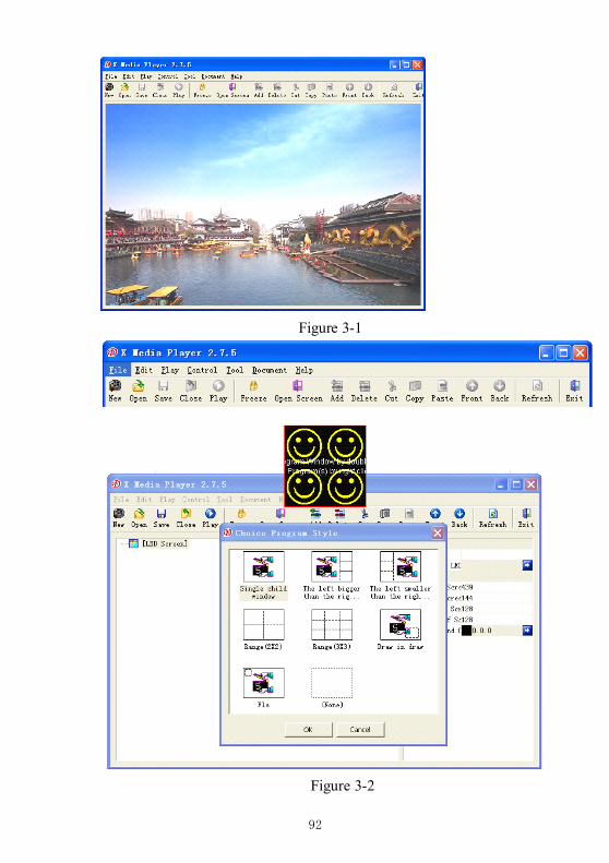
92
Figure 3-1
Figure 3-2
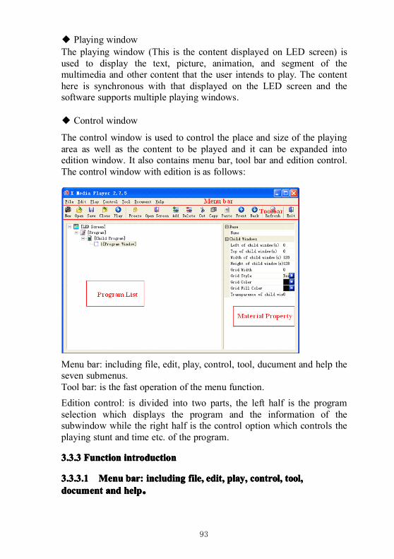
93
◆ Playing windowThe playing window (This is the content displayed on LED screen) isused to display the text, picture, animation, and segment of themultimedia and other content that the user intends to play. The contenthere is synchronous with that displayed on the LED screen and thesoftware supports multiple playing windows.
◆ Control window
The control window is used to control the place and size of the playingarea as well as the content to be played and it can be expanded intoedition window. It also contains menu bar, tool bar and edition control.The control window with edition is as follows:
Menu bar: including file, edit, play, control, tool, ducument and help theseven submenus.Tool bar: is the fast operation of the menu function.
Edition control: is divided into two parts, the left half is the programselection which displays the program and the information of thesubwindow while the right half is the control option which controls theplaying stunt and time etc. of the program.
3.3.33.3.33.3.33.3.3 FunctionFunctionFunctionFunction introductionintroductionintroductionintroduction
3.3.3.13.3.3.13.3.3.13.3.3.1 MenuMenuMenuMenu bar:bar:bar:bar: includingincludingincludingincluding file,file,file,file, edit,edit,edit,edit, play,play,play,play, control,control,control,control, tool,tool,tool,tool,documentdocumentdocumentdocument andandandand helphelphelphelp。
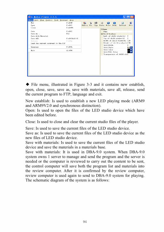
94
◆ File menu, illustrated in Figure 3-3 and it contains new establish,open, close, save, save as, save with materials, save all, release, sendthe current program to FTP, language and exit.
New establish: Is used to establish a new LED playing mode (ARM9and ARM9V2.0 and synchronous distinction).Open: Is used to open the files of the LED studio device which havebeen edited before.
Close: Is used to close and clear the current studio files of the player.
Save: Is used to save the current files of the LED studio device.Save as: Is used to save the current files of the LED studio device as thenew files of LED studio device.Save with materials: Is used to save the current files of the LED studiodevice and save the materials in a materials base.Save with materials: It is used in DBA-9.0 system. When DBA-9.0system owns 1 server to manage and send the program and the server isneeded or the computer is reviewed to carry out the content to be sent,the control computer will save both the program list and materials intothe review computer. After it is confirmed by the review computer,review computer is used again to send to DBA-9.0 system for playing.The schematic diagram of the system is as follows:
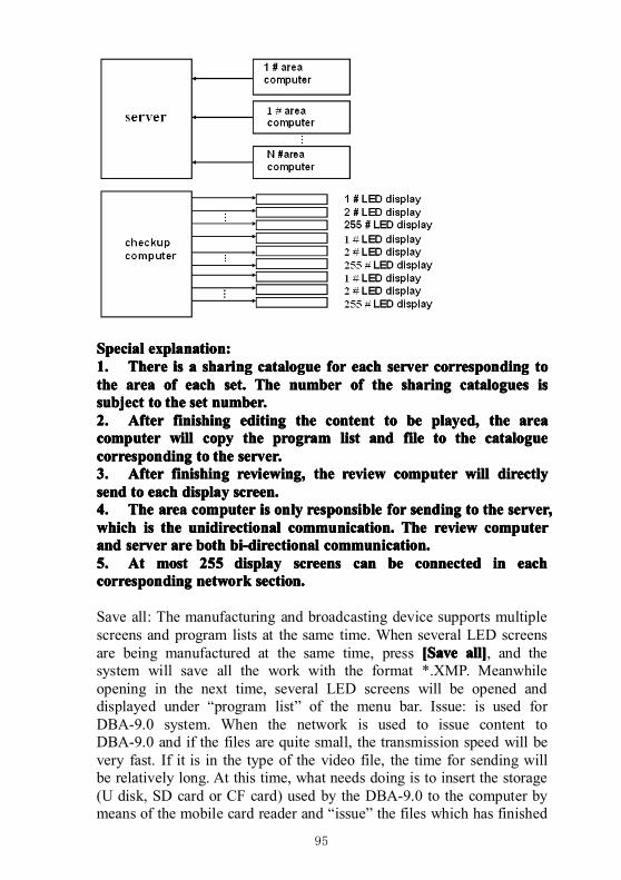
95
SpecialSpecialSpecialSpecial explanation:explanation:explanation:explanation:1.1.1.1. ThereThereThereThere isisisis aaaa sharingsharingsharingsharing cataloguecataloguecataloguecatalogue forforforfor eacheacheacheach serverserverserverserver correspondingcorrespondingcorrespondingcorresponding totototothethethethe areaareaareaarea ofofofof eacheacheacheach set.set.set.set. TheTheTheThe numbernumbernumbernumber ofofofof thethethethe sharingsharingsharingsharing cataloguescataloguescataloguescatalogues isisisissubjectsubjectsubjectsubject totototo thethethethe setsetsetset number.number.number.number.2.2.2.2. AfterAfterAfterAfter finishingfinishingfinishingfinishing editingeditingeditingediting thethethethe contentcontentcontentcontent totototo bebebebe played,played,played,played, thethethethe areaareaareaareacomputercomputercomputercomputer willwillwillwill copycopycopycopy thethethethe programprogramprogramprogram listlistlistlist andandandand filefilefilefile totototo thethethethe cataloguecataloguecataloguecataloguecorrespondingcorrespondingcorrespondingcorresponding totototo thethethethe server.server.server.server.3.3.3.3. AfterAfterAfterAfter finishingfinishingfinishingfinishing reviewing,reviewing,reviewing,reviewing, thethethethe reviewreviewreviewreview computercomputercomputercomputer willwillwillwill directlydirectlydirectlydirectlysendsendsendsend totototo eacheacheacheach displaydisplaydisplaydisplay screen.screen.screen.screen.4.4.4.4. TheTheTheThe areaareaareaarea computercomputercomputercomputer isisisis onlyonlyonlyonly responsibleresponsibleresponsibleresponsible forforforfor sendingsendingsendingsending totototo thethethethe server,server,server,server,whichwhichwhichwhich isisisis thethethethe unidirectionalunidirectionalunidirectionalunidirectional communication.communication.communication.communication. TheTheTheThe reviewreviewreviewreview computercomputercomputercomputerandandandand serverserverserverserver areareareare bothbothbothboth bi-directionalbi-directionalbi-directionalbi-directional communication.communication.communication.communication.5.5.5.5. AtAtAtAt mostmostmostmost 255255255255 displaydisplaydisplaydisplay screensscreensscreensscreens cancancancan bebebebe connectedconnectedconnectedconnected inininin eacheacheacheachcorrespondingcorrespondingcorrespondingcorresponding networknetworknetworknetwork section.section.section.section.
Save all: The manufacturing and broadcasting device supports multiplescreens and program lists at the same time. When several LED screensare being manufactured at the same time, press [[[[SSSSaveaveaveave all]all]all]all], and thesystem will save all the work with the format *.XMP. Meanwhileopening in the next time, several LED screens will be opened anddisplayed under “program list” of the menu bar. Issue: is used forDBA-9.0 system. When the network is used to issue content toDBA-9.0 and if the files are quite small, the transmission speed will bevery fast. If it is in the type of the video file, the time for sending willbe relatively long. At this time, what needs doing is to insert the storage(U disk, SD card or CF card) used by the DBA-9.0 to the computer bymeans of the mobile card reader and “issue” the files which has finished
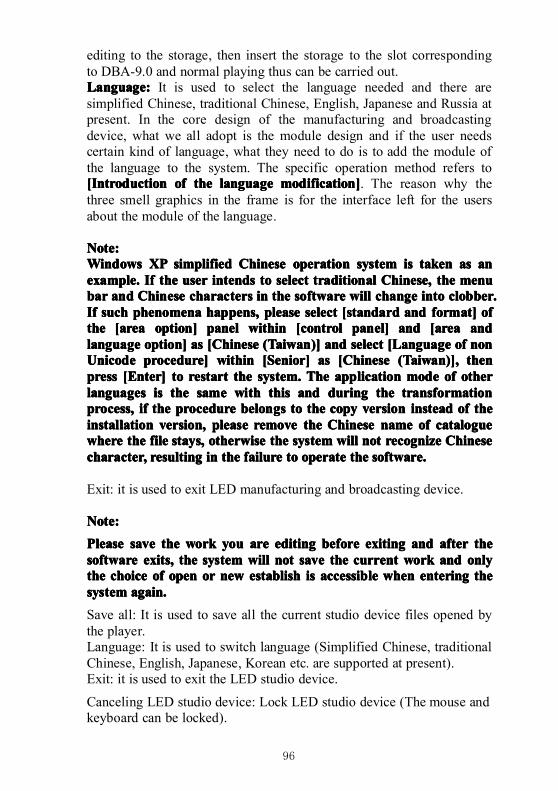
96
editing to the storage, then insert the storage to the slot correspondingto DBA-9.0 and normal playing thus can be carried out.Language:Language:Language:Language: It is used to select the language needed and there aresimplified Chinese, traditional Chinese, English, Japanese and Russia atpresent. In the core design of the manufacturing and broadcastingdevice, what we all adopt is the module design and if the user needscertain kind of language, what they need to do is to add the module ofthe language to the system. The specific operation method refers to[[[[IIIIntroductionntroductionntroductionntroduction ofofofof thethethethe languagelanguagelanguagelanguage modification]modification]modification]modification]. The reason why thethree smell graphics in the frame is for the interface left for the usersabout the module of the language.
Note:Note:Note:Note:WindowsWindowsWindowsWindows XPXPXPXP simplifiedsimplifiedsimplifiedsimplified ChineseChineseChineseChinese operationoperationoperationoperation systemsystemsystemsystem isisisis takentakentakentaken asasasas ananananexample.example.example.example. IfIfIfIf thethethethe useruseruseruser intendsintendsintendsintends totototo selectselectselectselect traditionaltraditionaltraditionaltraditional Chinese,Chinese,Chinese,Chinese, thethethethe menumenumenumenubarbarbarbar andandandand ChineseChineseChineseChinese characterscharacterscharacterscharacters inininin thethethethe softwaresoftwaresoftwaresoftware willwillwillwill changechangechangechange intointointointo clobber.clobber.clobber.clobber.IfIfIfIf suchsuchsuchsuch phenomenaphenomenaphenomenaphenomena happens,happens,happens,happens, pleasepleasepleaseplease selectselectselectselect [standard[standard[standard[standard andandandand format]format]format]format] ofofofofthethethethe [area[area[area[area option]option]option]option] panelpanelpanelpanel withinwithinwithinwithin [control[control[control[control panel]panel]panel]panel] andandandand [area[area[area[area andandandandlanguagelanguagelanguagelanguage option]option]option]option] asasasas [Chinese[Chinese[Chinese[Chinese (Taiwan)](Taiwan)](Taiwan)](Taiwan)] andandandand selectselectselectselect [[[[LLLLanguageanguageanguageanguage ofofofof nonnonnonnonUnicodeUnicodeUnicodeUnicode procedure]procedure]procedure]procedure] withinwithinwithinwithin [[[[SSSSenior]enior]enior]enior] asasasas [Chinese[Chinese[Chinese[Chinese (Taiwan)],(Taiwan)],(Taiwan)],(Taiwan)], thenthenthenthenpresspresspresspress [[[[EEEEnter]nter]nter]nter] totototo restartrestartrestartrestart thethethethe system.system.system.system. TheTheTheThe applicationapplicationapplicationapplication modemodemodemode ofofofof otherotherotherotherlanguageslanguageslanguageslanguages isisisis thethethethe samesamesamesame withwithwithwith thisthisthisthis andandandand duringduringduringduring thethethethe transformationtransformationtransformationtransformationprocess,process,process,process, ifififif thethethethe procedureprocedureprocedureprocedure belongsbelongsbelongsbelongs totototo thethethethe copycopycopycopy versionversionversionversion insteadinsteadinsteadinstead ofofofof thethethetheinstallationinstallationinstallationinstallation version,version,version,version, pleasepleasepleaseplease removeremoveremoveremove thethethethe ChineseChineseChineseChinese namenamenamename ofofofof cataloguecataloguecataloguecataloguewherewherewherewhere thethethethe filefilefilefile stays,stays,stays,stays, otherwiseotherwiseotherwiseotherwise thethethethe systemsystemsystemsystem willwillwillwill notnotnotnot recognizerecognizerecognizerecognize ChineseChineseChineseChinesecharacter,character,character,character, resultingresultingresultingresulting inininin thethethethe failurefailurefailurefailure totototo operateoperateoperateoperate thethethethe software.software.software.software.
Exit: it is used to exit LED manufacturing and broadcasting device.
Note:Note:Note:Note:
PleasePleasePleasePlease savesavesavesave thethethethe workworkworkwork youyouyouyou areareareare editingeditingeditingediting beforebeforebeforebefore exitingexitingexitingexiting andandandand afterafterafterafter thethethethesoftwaresoftwaresoftwaresoftware exits,exits,exits,exits, thethethethe systemsystemsystemsystem willwillwillwill notnotnotnot savesavesavesave thethethethe currentcurrentcurrentcurrent workworkworkwork andandandand onlyonlyonlyonlythethethethe choicechoicechoicechoice ofofofof openopenopenopen orororor newnewnewnew establishestablishestablishestablish isisisis accessibleaccessibleaccessibleaccessible whenwhenwhenwhen enteringenteringenteringentering thethethethesystemsystemsystemsystem again.again.again.again.
Save all: It is used to save all the current studio device files opened bythe player.Language: It is used to switch language (Simplified Chinese, traditionalChinese, English, Japanese, Korean etc. are supported at present).Exit: it is used to exit the LED studio device.
Canceling LED studio device: Lock LED studio device (The mouse andkeyboard can be locked).
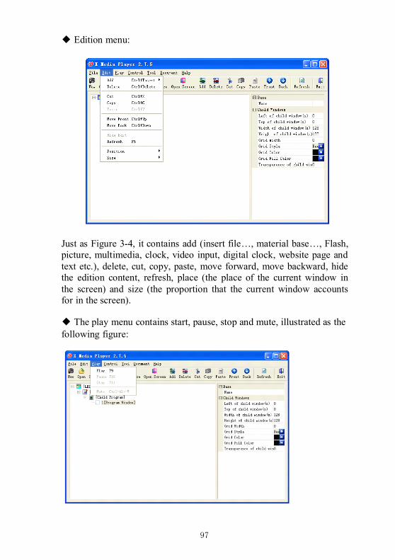
97
◆ Edition menu:
Just as Figure 3-4, it contains add (insert file…, material base…, Flash,picture, multimedia, clock, video input, digital clock, website page andtext etc.), delete, cut, copy, paste, move forward, move backward, hidethe edition content, refresh, place (the place of the current window inthe screen) and size (the proportion that the current window accountsfor in the screen).
◆ The play menu contains start, pause, stop and mute, illustrated as thefollowing figure:
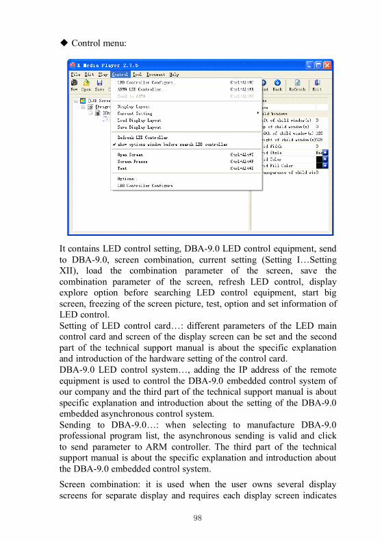
98
◆ Control menu:
It contains LED control setting, DBA-9.0 LED control equipment, sendto DBA-9.0, screen combination, current setting (Setting I…SettingXII), load the combination parameter of the screen, save thecombination parameter of the screen, refresh LED control, displayexplore option before searching LED control equipment, start bigscreen, freezing of the screen picture, test, option and set information ofLED control.Setting of LED control card…: different parameters of the LED maincontrol card and screen of the display screen can be set and the secondpart of the technical support manual is about the specific explanationand introduction of the hardware setting of the control card.DBA-9.0 LED control system…, adding the IP address of the remoteequipment is used to control the DBA-9.0 embedded control system ofour company and the third part of the technical support manual is aboutspecific explanation and introduction about the setting of the DBA-9.0embedded asynchronous control system.Sending to DBA-9.0…: when selecting to manufacture DBA-9.0professional program list, the asynchronous sending is valid and clickto send parameter to ARM controller. The third part of the technicalsupport manual is about the specific explanation and introduction aboutthe DBA-9.0 embedded control system.
Screen combination: it is used when the user owns several displayscreens for separate display and requires each display screen indicates
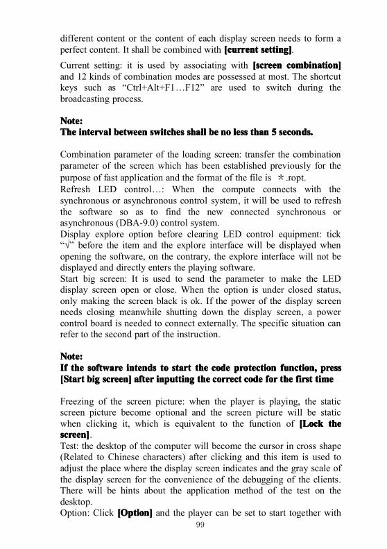
99
different content or the content of each display screen needs to form aperfect content. It shall be combined with [current[current[current[current setting]setting]setting]setting].
Current setting: it is used by associating with [screen[screen[screen[screen combination]combination]combination]combination]and 12 kinds of combination modes are possessed at most. The shortcutkeys such as “Ctrl+Alt+F1…F12” are used to switch during thebroadcasting process.
Note:Note:Note:Note:TheTheTheThe intervalintervalintervalinterval betweenbetweenbetweenbetween switchesswitchesswitchesswitches shallshallshallshall bebebebe nononono lesslesslessless thanthanthanthan 5555 seconds.seconds.seconds.seconds.
Combination parameter of the loading screen: transfer the combinationparameter of the screen which has been established previously for thepurpose of fast application and the format of the file is *.ropt.Refresh LED control…: When the compute connects with thesynchronous or asynchronous control system, it will be used to refreshthe software so as to find the new connected synchronous orasynchronous (DBA-9.0) control system.Display explore option before clearing LED control equipment: tick“√” before the item and the explore interface will be displayed whenopening the software, on the contrary, the explore interface will not bedisplayed and directly enters the playing software.Start big screen: It is used to send the parameter to make the LEDdisplay screen open or close. When the option is under closed status,only making the screen black is ok. If the power of the display screenneeds closing meanwhile shutting down the display screen, a powercontrol board is needed to connect externally. The specific situation canrefer to the second part of the instruction.
Note:Note:Note:Note:IfIfIfIf thethethethe softwaresoftwaresoftwaresoftware intendsintendsintendsintends totototo startstartstartstart thethethethe codecodecodecode protectionprotectionprotectionprotection function,function,function,function, presspresspresspress[[[[SSSStarttarttarttart bigbigbigbig screen]screen]screen]screen] afterafterafterafter inputtinginputtinginputtinginputting thethethethe correctcorrectcorrectcorrect codecodecodecode forforforfor thethethethe firstfirstfirstfirst timetimetimetime
Freezing of the screen picture: when the player is playing, the staticscreen picture become optional and the screen picture will be staticwhen clicking it, which is equivalent to the function of [[[[LLLLockockockock thethethethescreen]screen]screen]screen].Test: the desktop of the computer will become the cursor in cross shape(Related to Chinese characters) after clicking and this item is used toadjust the place where the display screen indicates and the gray scale ofthe display screen for the convenience of the debugging of the clients.There will be hints about the application method of the test on thedesktop.Option: Click [[[[OOOOption]ption]ption]ption] and the player can be set to start together with
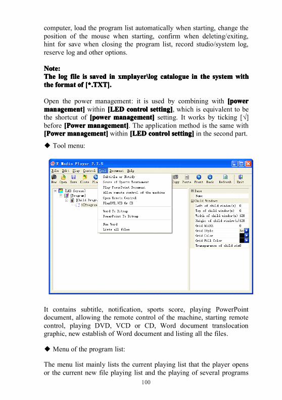
100
computer, load the program list automatically when starting, change theposition of the mouse when starting, confirm when deleting/exiting,hint for save when closing the program list, record studio/system log,reserve log and other options.
Note:Note:Note:Note:TheTheTheThe loglogloglog filefilefilefile isisisis savedsavedsavedsaved inininin xmplayer\logxmplayer\logxmplayer\logxmplayer\log cataloguecataloguecataloguecatalogue inininin thethethethe systemsystemsystemsystem withwithwithwiththethethethe formatformatformatformat ofofofof [*.TXT].[*.TXT].[*.TXT].[*.TXT].
Open the power management: it is used by combining with [power[power[power[powermanagement]management]management]management] within [LED[LED[LED[LED controlcontrolcontrolcontrol setting]setting]setting]setting], which is equivalent to bethe shortcut of [power[power[power[power management]management]management]management] setting. It works by ticking [√]before [[[[PPPPowerowerowerower management]management]management]management]. The application method is the same with[[[[PPPPowerowerowerower management]management]management]management] within [LED[LED[LED[LED controlcontrolcontrolcontrol setting]setting]setting]setting] in the second part.
◆ Tool menu:
It contains subtitle, notification, sports score, playing PowerPointdocument, allowing the remote control of the machine, starting remotecontrol, playing DVD, VCD or CD, Word document translocationgraphic, new establish of Word document and listing all the files.
◆ Menu of the program list:
The menu list mainly lists the current playing list that the player opensor the current new file playing list and the playing of several programs
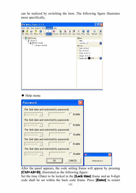
101
can be realized by switching the item. The following figure illustratesmore specifically,
◆ Help menu
After the panel appears, the code setting frame will appear by pressing[Ctrl+Alt+D][Ctrl+Alt+D][Ctrl+Alt+D][Ctrl+Alt+D], illustrated as the following figure:Set the time (Date) to be locked in the [[[[LLLLockockockock time]time]time]time] frame and an 8-digitcode shall be set within the back code frame. Press [[[[EEEEnter]nter]nter]nter] to restart
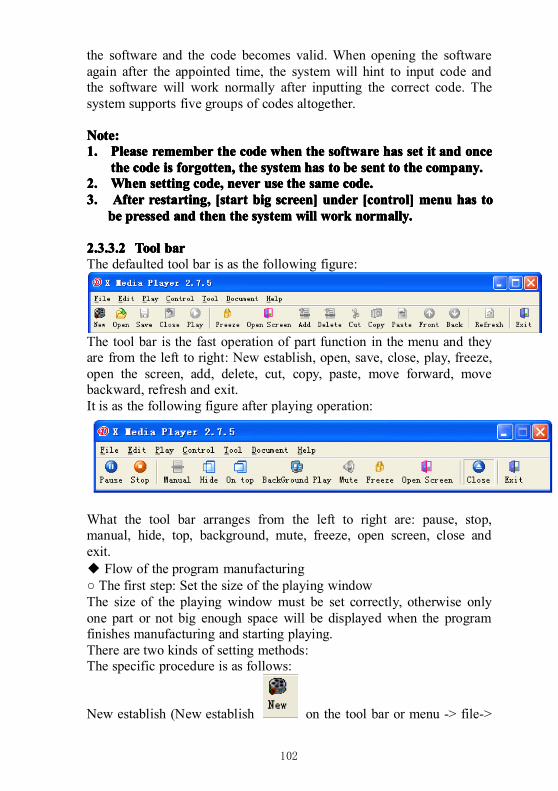
102
the software and the code becomes valid. When opening the softwareagain after the appointed time, the system will hint to input code andthe software will work normally after inputting the correct code. Thesystem supports five groups of codes altogether.
Note:Note:Note:Note:1.1.1.1. PleasePleasePleasePlease rememberrememberrememberremember thethethethe codecodecodecode whenwhenwhenwhen thethethethe softwaresoftwaresoftwaresoftware hashashashas setsetsetset itititit andandandand onceonceonceonce
thethethethe codecodecodecode isisisis forgotten,forgotten,forgotten,forgotten, thethethethe systemsystemsystemsystem hashashashas totototo bebebebe sentsentsentsent totototo thethethethe company.company.company.company.2.2.2.2. WhenWhenWhenWhen settingsettingsettingsetting code,code,code,code, nevernevernevernever useuseuseuse thethethethe samesamesamesame code.code.code.code.3.3.3.3. AfterAfterAfterAfter restarting,restarting,restarting,restarting, [start[start[start[start bigbigbigbig screen]screen]screen]screen] underunderunderunder [control][control][control][control] menumenumenumenu hashashashas totototo
bebebebe pressedpressedpressedpressed andandandand thenthenthenthen thethethethe systemsystemsystemsystem willwillwillwill workworkworkwork normally.normally.normally.normally.
2.3.3.22.3.3.22.3.3.22.3.3.2 ToolToolToolTool barbarbarbarThe defaulted tool bar is as the following figure:
The tool bar is the fast operation of part function in the menu and theyare from the left to right: New establish, open, save, close, play, freeze,open the screen, add, delete, cut, copy, paste, move forward, movebackward, refresh and exit.It is as the following figure after playing operation:
What the tool bar arranges from the left to right are: pause, stop,manual, hide, top, background, mute, freeze, open screen, close andexit.◆ Flow of the program manufacturing○ The first step: Set the size of the playing windowThe size of the playing window must be set correctly, otherwise onlyone part or not big enough space will be displayed when the programfinishes manufacturing and starting playing.There are two kinds of setting methods:The specific procedure is as follows:
New establish (New establish on the tool bar or menu -> file->
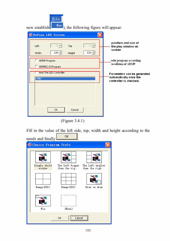
103
new establish ), the following figure will appear:
(Figure 3.4.1)
Fill in the value of the left side, top, width and height according to the
needs and finally .
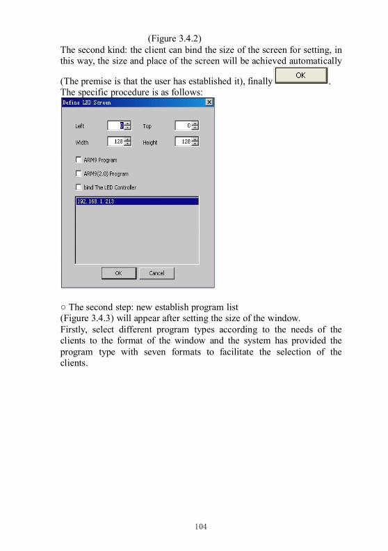
104
(Figure 3.4.2)The second kind: the client can bind the size of the screen for setting, inthis way, the size and place of the screen will be achieved automatically
(The premise is that the user has established it), finally .The specific procedure is as follows:
○ The second step: new establish program list(Figure 3.4.3) will appear after setting the size of the window.Firstly, select different program types according to the needs of theclients to the format of the window and the system has provided theprogram type with seven formats to facilitate the selection of theclients.
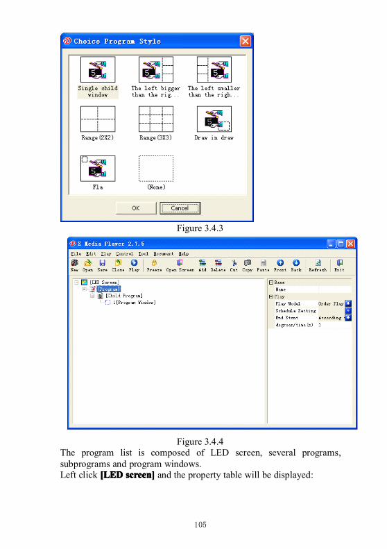
105
Figure 3.4.3
Figure 3.4.4The program list is composed of LED screen, several programs,subprograms and program windows.Left click [LED[LED[LED[LED screen]screen]screen]screen] and the property table will be displayed:
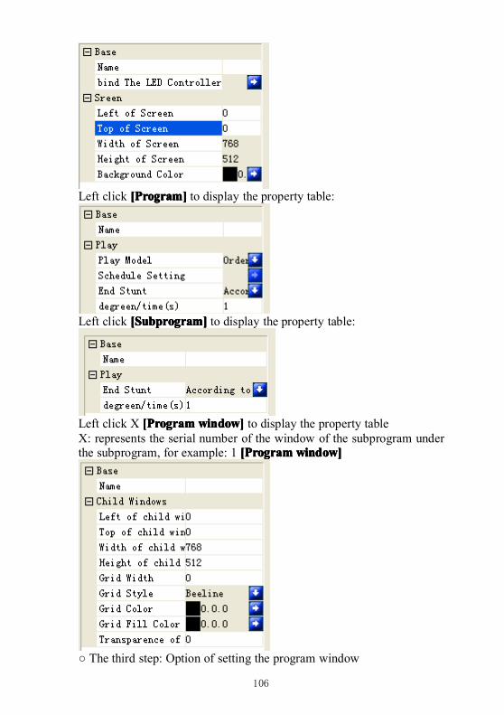
106
Left click [[[[PPPProgram]rogram]rogram]rogram] to display the property table:
Left click [[[[SSSSubprogram]ubprogram]ubprogram]ubprogram] to display the property table:
Left click X [[[[PPPProgramrogramrogramrogram window]window]window]window] to display the property tableX: represents the serial number of the window of the subprogram underthe subprogram, for example: 1 [[[[PPPProgramrogramrogramrogram window]window]window]window]
○ The third step: Option of setting the program window
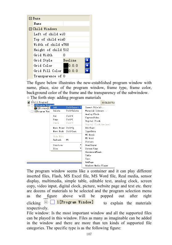
107
The figure below illustrates the new-established program window withname, place, size of the program window, frame type, frame color,background color of the frame and the transparency of the subwindow.○ The forth step: adding program materials
The program window seems like a container and it can play differentinserted files, Flash, MS Excel file, MS Word file, Real media, sensordisplay, multimedia, simple table, editable text, analog clock, screencopy, video input, digital clock, picture, website page and text etc. thereare dozens of materials to be selected and the program selection menuas the figure above will be popped out after right
clicking to explain the materialsrespectively.File window: Is the most important window and all the supported filescan be played in this window. Files as many as imaginable can be addedin the window and there are more than ten kinds of supported filecategories. The specific type is as the following figure:
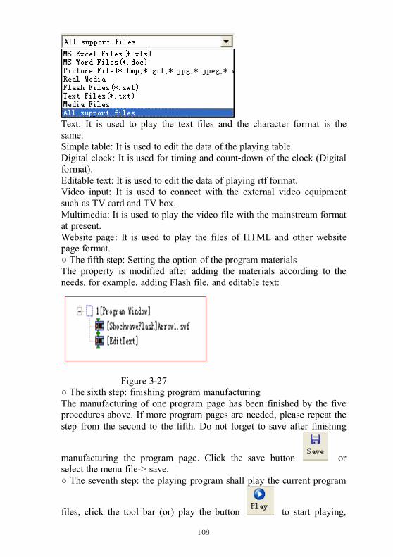
108
Text: It is used to play the text files and the character format is thesame.Simple table: It is used to edit the data of the playing table.Digital clock: It is used for timing and count-down of the clock (Digitalformat).Editable text: It is used to edit the data of playing rtf format.Video input: It is used to connect with the external video equipmentsuch as TV card and TV box.Multimedia: It is used to play the video file with the mainstream formatat present.Website page: It is used to play the files of HTML and other websitepage format.○ The fifth step: Setting the option of the program materialsThe property is modified after adding the materials according to theneeds, for example, adding Flash file, and editable text:
Figure 3-27○ The sixth step: finishing program manufacturingThe manufacturing of one program page has been finished by the fiveprocedures above. If more program pages are needed, please repeat thestep from the second to the fifth. Do not forget to save after finishing
manufacturing the program page. Click the save button orselect the menu file-> save.○ The seventh step: the playing program shall play the current program
files, click the tool bar (or) play the button to start playing,
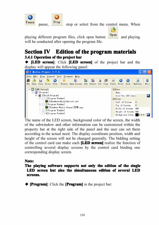
109
pause, stop or select from the control menu. When
playing different program files, click open button and playingwill be conducted after opening the program file.
SectionSectionSectionSection IVIVIVIV EditionEditionEditionEdition ofofofof thethethethe programprogramprogramprogrammaterialsmaterialsmaterialsmaterials3.4.13.4.13.4.13.4.1 OperationOperationOperationOperation ofofofof thethethethe projectprojectprojectproject barbarbarbar◆ [LED[LED[LED[LED screen]screen]screen]screen]: Click [LED[LED[LED[LED screen]screen]screen]screen] of the project bar and thedisplay will appear the following panel:
The name of the LED screen, background color of the screen, the widthof the subwindow and other information can be customized within theproperty bar at the right side of the panel and the user can set themaccording to the actual need. The display coordinate position, width andheight of the screen will not be changed generally. The bidding settingof the control card can make each [LED[LED[LED[LED screen]screen]screen]screen] realize the function ofcontrolling several display screens by the control card binding onecorresponding display screen.
Note:Note:Note:Note:TheTheTheThe playingplayingplayingplaying softwaresoftwaresoftwaresoftware supportssupportssupportssupports notnotnotnot onlyonlyonlyonly thethethethe editioneditioneditionedition ofofofof thethethethe singlesinglesinglesingleLEDLEDLEDLED screenscreenscreenscreen butbutbutbut alsoalsoalsoalso thethethethe simultaneoussimultaneoussimultaneoussimultaneous editioneditioneditionedition ofofofof severalseveralseveralseveral LEDLEDLEDLEDscreens.screens.screens.screens.
◆ [[[[PPPProgram]rogram]rogram]rogram]: Click the [[[[PPPProgram]rogram]rogram]rogram] in the project bar:
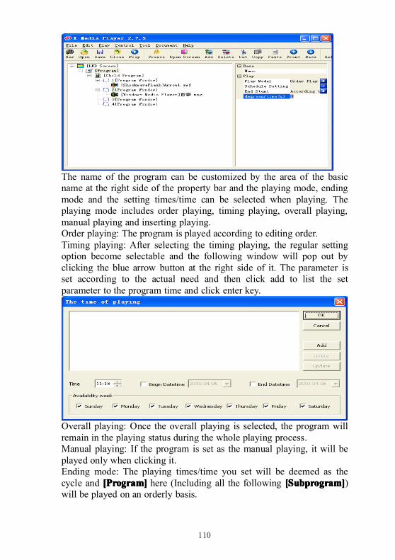
110
The name of the program can be customized by the area of the basicname at the right side of the property bar and the playing mode, endingmode and the setting times/time can be selected when playing. Theplaying mode includes order playing, timing playing, overall playing,manual playing and inserting playing.Order playing: The program is played according to editing order.Timing playing: After selecting the timing playing, the regular settingoption become selectable and the following window will pop out byclicking the blue arrow button at the right side of it. The parameter isset according to the actual need and then click add to list the setparameter to the program time and click enter key.
Overall playing: Once the overall playing is selected, the program willremain in the playing status during the whole playing process.Manual playing: If the program is set as the manual playing, it will beplayed only when clicking it.Ending mode: The playing times/time you set will be deemed as thecycle and [[[[PPPProgram]rogram]rogram]rogram] here (Including all the following [[[[SSSSubprogram]ubprogram]ubprogram]ubprogram])will be played on an orderly basis.
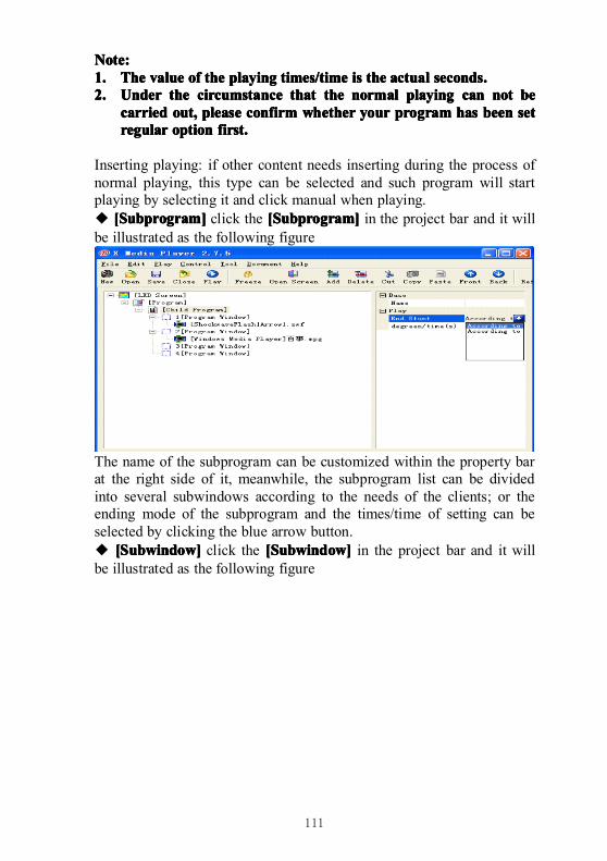
111
Note:Note:Note:Note:1.1.1.1. TheTheTheThe valuevaluevaluevalue ofofofof thethethethe playingplayingplayingplaying times/timetimes/timetimes/timetimes/time isisisis thethethethe actualactualactualactual seconds.seconds.seconds.seconds.2.2.2.2. UnderUnderUnderUnder thethethethe circumstancecircumstancecircumstancecircumstance thatthatthatthat thethethethe normalnormalnormalnormal playingplayingplayingplaying cancancancan notnotnotnot bebebebe
carriedcarriedcarriedcarried out,out,out,out, pleasepleasepleaseplease confirmconfirmconfirmconfirm whetherwhetherwhetherwhether youryouryouryour programprogramprogramprogram hashashashas beenbeenbeenbeen setsetsetsetregularregularregularregular optionoptionoptionoption first.first.first.first.
Inserting playing: if other content needs inserting during the process ofnormal playing, this type can be selected and such program will startplaying by selecting it and click manual when playing.◆ [[[[SSSSubprogram]ubprogram]ubprogram]ubprogram] click the [[[[SSSSubprogram]ubprogram]ubprogram]ubprogram] in the project bar and it willbe illustrated as the following figure
The name of the subprogram can be customized within the property barat the right side of it, meanwhile, the subprogram list can be dividedinto several subwindows according to the needs of the clients; or theending mode of the subprogram and the times/time of setting can beselected by clicking the blue arrow button.◆ [[[[SSSSubwindow]ubwindow]ubwindow]ubwindow] click the [[[[SSSSubwindow]ubwindow]ubwindow]ubwindow] in the project bar and it willbe illustrated as the following figure
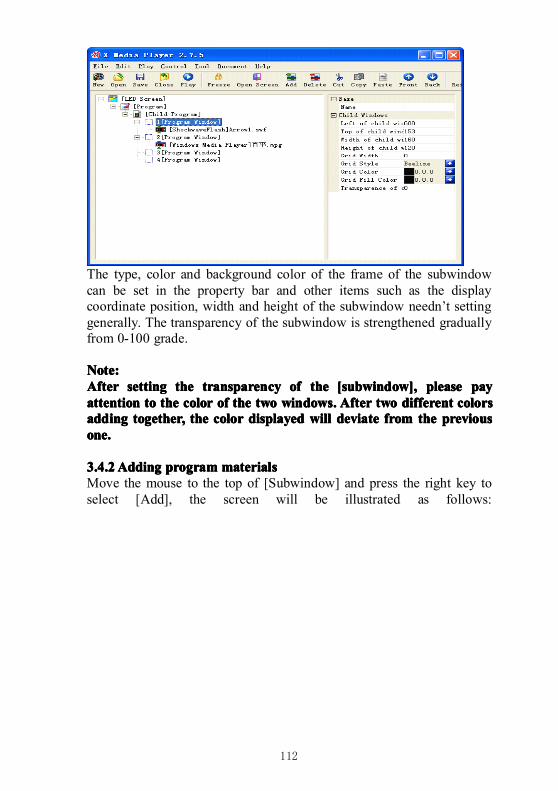
112
The type, color and background color of the frame of the subwindowcan be set in the property bar and other items such as the displaycoordinate position, width and height of the subwindow needn’t settinggenerally. The transparency of the subwindow is strengthened graduallyfrom 0-100 grade.
Note:Note:Note:Note:AfterAfterAfterAfter settingsettingsettingsetting thethethethe transparencytransparencytransparencytransparency ofofofof thethethethe [subwindow],[subwindow],[subwindow],[subwindow], pleasepleasepleaseplease paypaypaypayattentionattentionattentionattention totototo thethethethe colorcolorcolorcolor ofofofof thethethethe twotwotwotwo windows.windows.windows.windows. AfterAfterAfterAfter twotwotwotwo differentdifferentdifferentdifferent colorscolorscolorscolorsaddingaddingaddingadding together,together,together,together, thethethethe colorcolorcolorcolor displayeddisplayeddisplayeddisplayed willwillwillwill deviatedeviatedeviatedeviate fromfromfromfrom thethethethe previouspreviouspreviouspreviousone.one.one.one.
3.4.23.4.23.4.23.4.2AddingAddingAddingAdding programprogramprogramprogram materialsmaterialsmaterialsmaterialsMove the mouse to the top of [Subwindow] and press the right key toselect [Add], the screen will be illustrated as follows:
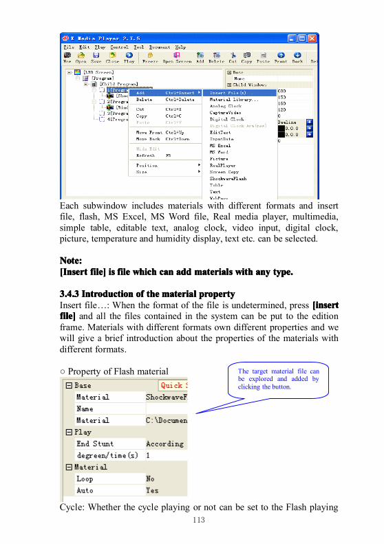
113
Each subwindow includes materials with different formats and insertfile, flash, MS Excel, MS Word file, Real media player, multimedia,simple table, editable text, analog clock, video input, digital clock,picture, temperature and humidity display, text etc. can be selected.
Note:Note:Note:Note:[Insert[Insert[Insert[Insert file]file]file]file] isisisis filefilefilefile whichwhichwhichwhich cancancancan addaddaddadd materialsmaterialsmaterialsmaterials withwithwithwith anyanyanyany type.type.type.type.
3.4.33.4.33.4.33.4.3 IntroductionIntroductionIntroductionIntroduction ofofofof thethethethe materialmaterialmaterialmaterial propertypropertypropertypropertyInsert file…: When the format of the file is undetermined, press [insert[insert[insert[insertfile]file]file]file] and all the files contained in the system can be put to the editionframe. Materials with different formats own different properties and wewill give a brief introduction about the properties of the materials withdifferent formats.
○ Property of Flash material
Cycle: Whether the cycle playing or not can be set to the Flash playing
The target material file canbe explored and added byclicking the button.
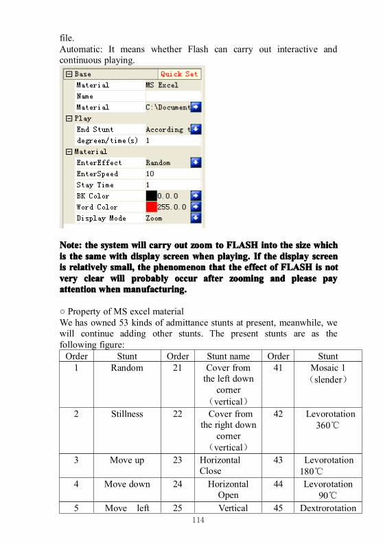
114
file.Automatic: It means whether Flash can carry out interactive andcontinuous playing.
Note:Note:Note:Note: thethethethe systemsystemsystemsystem willwillwillwill carrycarrycarrycarry outoutoutout zoomzoomzoomzoom totototo FLASHFLASHFLASHFLASH intointointointo thethethethe sizesizesizesize whichwhichwhichwhichisisisis thethethethe samesamesamesame withwithwithwith displaydisplaydisplaydisplay screenscreenscreenscreen whenwhenwhenwhen playing.playing.playing.playing. IfIfIfIf thethethethe displaydisplaydisplaydisplay screenscreenscreenscreenisisisis relativelyrelativelyrelativelyrelatively small,small,small,small, thethethethe phenomenonphenomenonphenomenonphenomenon thatthatthatthat thethethethe effecteffecteffecteffect ofofofof FLASHFLASHFLASHFLASH isisisis notnotnotnotveryveryveryvery clearclearclearclear willwillwillwill probablyprobablyprobablyprobably occuroccuroccuroccur afterafterafterafter zoomingzoomingzoomingzooming andandandand pleasepleasepleaseplease paypaypaypayattentionattentionattentionattention whenwhenwhenwhen manufacturing.manufacturing.manufacturing.manufacturing.
○ Property of MS excel materialWe has owned 53 kinds of admittance stunts at present, meanwhile, wewill continue adding other stunts. The present stunts are as thefollowing figure:Order Stunt Order Stunt name Order Stunt1 Random 21 Cover from
the left downcorner
(vertical)
41 Mosaic 1(slender)
2 Stillness 22 Cover fromthe right down
corner(vertical)
42 Levorotation360℃
3 Move up 23 HorizontalClose
43 Levorotation180℃
4 Move down 24 HorizontalOpen
44 Levorotation90℃
5 Move left 25 Vertical 45 Dextrorotation
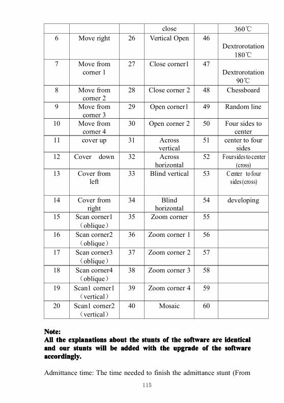
115
close 360℃6 Move right 26 Vertical Open 46
Dextrorotation180℃
7 Move fromcorner 1
27 Close corner1 47Dextrorotation
90℃8 Move from
corner 228 Close corner 2 48 Chessboard
9 Move fromcorner 3
29 Open corner1 49 Random line
10 Move fromcorner 4
30 Open corner 2 50 Four sides tocenter
11 cover up 31 Acrossvertical
51 center to foursides
12 Cover down 32 Acrosshorizontal
52 Foursides to center(cross)
13 Cover fromleft
33 Blind vertical 53 Center to foursides (cross)
14 Cover fromright
34 Blindhorizontal
54 developing
15 Scan corner1(oblique)
35 Zoom corner 55
16 Scan corner2(oblique)
36 Zoom corner 1 56
17 Scan corner3(oblique)
37 Zoom corner 2 57
18 Scan corner4(oblique)
38 Zoom corner 3 58
19 Scan1 corner1(vertical)
39 Zoom corner 4 59
20 Scan1 corner2(vertical)
40 Mosaic 60
Note:Note:Note:Note:AllAllAllAll thethethethe explanationsexplanationsexplanationsexplanations aboutaboutaboutabout thethethethe stuntsstuntsstuntsstunts ofofofof thethethethe softwaresoftwaresoftwaresoftware areareareare identicalidenticalidenticalidenticalandandandand ourourourour stuntsstuntsstuntsstunts willwillwillwill bebebebe addedaddedaddedadded withwithwithwith thethethethe upgradeupgradeupgradeupgrade ofofofof thethethethe softwaresoftwaresoftwaresoftwareaccordingly.accordingly.accordingly.accordingly.
Admittance time: The time needed to finish the admittance stunt (From
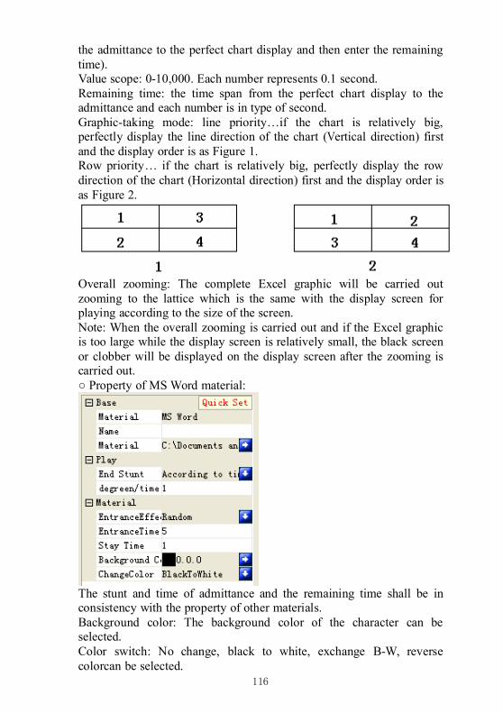
116
the admittance to the perfect chart display and then enter the remainingtime).Value scope: 0-10,000. Each number represents 0.1 second.Remaining time: the time span from the perfect chart display to theadmittance and each number is in type of second.Graphic-taking mode: line priority…if the chart is relatively big,perfectly display the line direction of the chart (Vertical direction) firstand the display order is as Figure 1.Row priority… if the chart is relatively big, perfectly display the rowdirection of the chart (Horizontal direction) first and the display order isas Figure 2.
Overall zooming: The complete Excel graphic will be carried outzooming to the lattice which is the same with the display screen forplaying according to the size of the screen.Note: When the overall zooming is carried out and if the Excel graphicis too large while the display screen is relatively small, the black screenor clobber will be displayed on the display screen after the zooming iscarried out.○ Property of MS Word material:
The stunt and time of admittance and the remaining time shall be inconsistency with the property of other materials.Background color: The background color of the character can beselected.Color switch: No change, black to white, exchange B-W, reversecolorcan be selected.
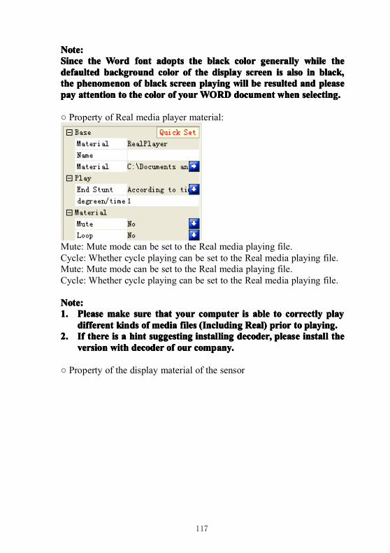
117
Note:Note:Note:Note:SinceSinceSinceSince thethethethe WordWordWordWord fontfontfontfont adoptsadoptsadoptsadopts thethethethe blackblackblackblack colorcolorcolorcolor generallygenerallygenerallygenerally whilewhilewhilewhile thethethethedefaulteddefaulteddefaulteddefaulted backgroundbackgroundbackgroundbackground colorcolorcolorcolor ofofofof thethethethe displaydisplaydisplaydisplay screenscreenscreenscreen isisisis alsoalsoalsoalso inininin black,black,black,black,thethethethe phenomenonphenomenonphenomenonphenomenon ofofofof blackblackblackblack screenscreenscreenscreen playingplayingplayingplaying willwillwillwill bebebebe resultedresultedresultedresulted andandandand pleasepleasepleasepleasepaypaypaypay attentionattentionattentionattention totototo thethethethe colorcolorcolorcolor ofofofof youryouryouryourWORDWORDWORDWORD documentdocumentdocumentdocument whenwhenwhenwhen selecting.selecting.selecting.selecting.
○ Property of Real media player material:
Mute: Mute mode can be set to the Real media playing file.Cycle: Whether cycle playing can be set to the Real media playing file.Mute: Mute mode can be set to the Real media playing file.Cycle: Whether cycle playing can be set to the Real media playing file.
Note:Note:Note:Note:1.1.1.1. PleasePleasePleasePlease makemakemakemake suresuresuresure thatthatthatthat youryouryouryour computercomputercomputercomputer isisisis ableableableable totototo correctlycorrectlycorrectlycorrectly playplayplayplay
differentdifferentdifferentdifferent kindskindskindskinds ofofofof mediamediamediamedia filesfilesfilesfiles ((((IIIIncludingncludingncludingncluding Real)Real)Real)Real) priorpriorpriorprior totototo playing.playing.playing.playing.2.2.2.2. IfIfIfIf theretheretherethere isisisis aaaa hinthinthinthint suggestingsuggestingsuggestingsuggesting installinginstallinginstallinginstalling decoder,decoder,decoder,decoder, pleasepleasepleaseplease installinstallinstallinstall thethethethe
versionversionversionversion withwithwithwith decoderdecoderdecoderdecoder ofofofof ourourourour company.company.company.company.
○ Property of the display material of the sensor
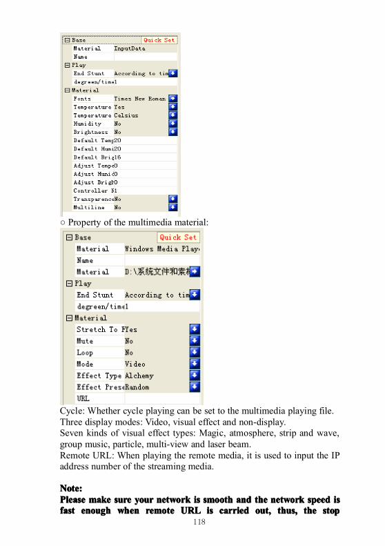
118
○ Property of the multimedia material:
Cycle: Whether cycle playing can be set to the multimedia playing file.Three display modes: Video, visual effect and non-display.Seven kinds of visual effect types: Magic, atmosphere, strip and wave,group music, particle, multi-view and laser beam.Remote URL: When playing the remote media, it is used to input the IPaddress number of the streaming media.
Note:Note:Note:Note:PleasePleasePleasePlease makemakemakemake suresuresuresure youryouryouryour networknetworknetworknetwork isisisis smoothsmoothsmoothsmooth andandandand thethethethe networknetworknetworknetwork speedspeedspeedspeed isisisisfastfastfastfast enoughenoughenoughenough whenwhenwhenwhen remoteremoteremoteremote URLURLURLURL isisisis carriedcarriedcarriedcarried out,out,out,out, thus,thus,thus,thus, thethethethe stopstopstopstop
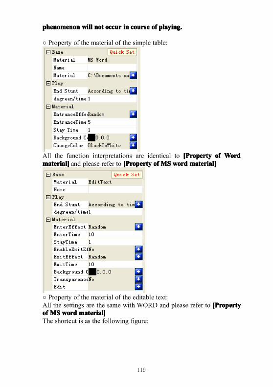
119
phenomenonphenomenonphenomenonphenomenon willwillwillwill notnotnotnot occuroccuroccuroccur inininin coursecoursecoursecourse ofofofof playing.playing.playing.playing.
○ Property of the material of the simple table:
All the function interpretations are identical to [[[[PPPPropertyropertyropertyroperty ofofofof WordWordWordWordmaterial]material]material]material] and please refer to [[[[PPPPropertyropertyropertyroperty ofofofof MSMSMSMSwwwwordordordord material]material]material]material]
○ Property of the material of the editable text:All the settings are the same with WORD and please refer to [[[[PPPPropertyropertyropertyropertyofofofof MSMSMSMSwwwwordordordord material]material]material]material]The shortcut is as the following figure:
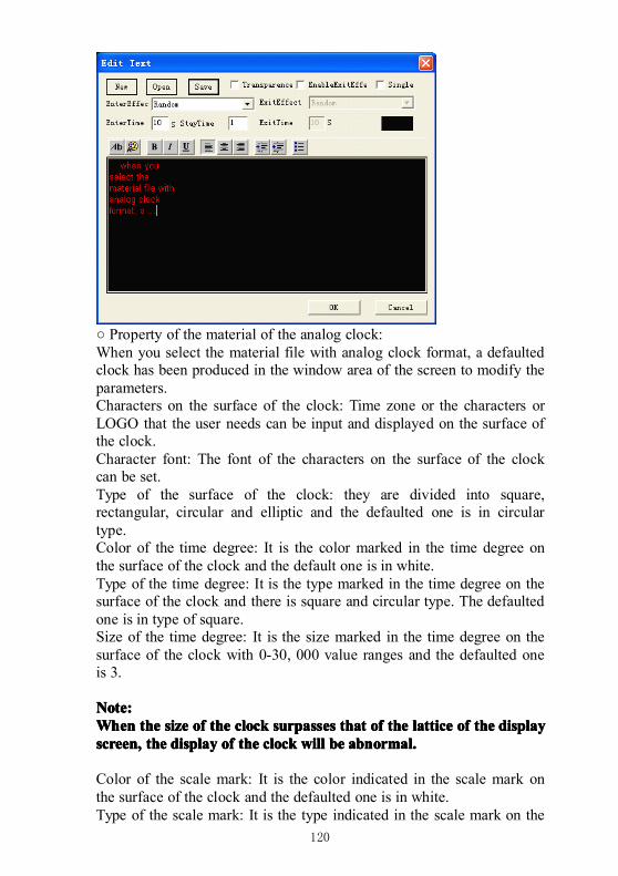
120
○ Property of the material of the analog clock:When you select the material file with analog clock format, a defaultedclock has been produced in the window area of the screen to modify theparameters.Characters on the surface of the clock: Time zone or the characters orLOGO that the user needs can be input and displayed on the surface ofthe clock.Character font: The font of the characters on the surface of the clockcan be set.Type of the surface of the clock: they are divided into square,rectangular, circular and elliptic and the defaulted one is in circulartype.Color of the time degree: It is the color marked in the time degree onthe surface of the clock and the default one is in white.Type of the time degree: It is the type marked in the time degree on thesurface of the clock and there is square and circular type. The defaultedone is in type of square.Size of the time degree: It is the size marked in the time degree on thesurface of the clock with 0-30, 000 value ranges and the defaulted oneis 3.
Note:Note:Note:Note:WhenWhenWhenWhen thethethethe sizesizesizesize ofofofof thethethethe clockclockclockclock surpassessurpassessurpassessurpasses thatthatthatthat ofofofof thethethethe latticelatticelatticelattice ofofofof thethethethe displaydisplaydisplaydisplayscreen,screen,screen,screen, thethethethe displaydisplaydisplaydisplay ofofofof thethethethe clockclockclockclock willwillwillwill bebebebe abnormal.abnormal.abnormal.abnormal.
Color of the scale mark: It is the color indicated in the scale mark onthe surface of the clock and the defaulted one is in white.Type of the scale mark: It is the type indicated in the scale mark on the
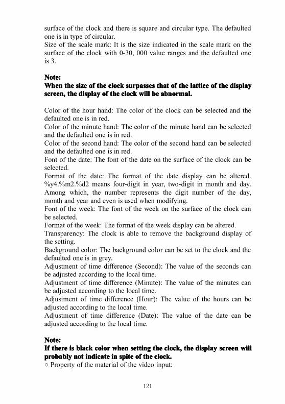
121
surface of the clock and there is square and circular type. The defaultedone is in type of circular.Size of the scale mark: It is the size indicated in the scale mark on thesurface of the clock with 0-30, 000 value ranges and the defaulted oneis 3.
Note:Note:Note:Note:WhenWhenWhenWhen thethethethe sizesizesizesize ofofofof thethethethe clockclockclockclock surpassessurpassessurpassessurpasses thatthatthatthat ofofofof thethethethe latticelatticelatticelattice ofofofof thethethethe displaydisplaydisplaydisplayscreen,screen,screen,screen, thethethethe displaydisplaydisplaydisplay ofofofof thethethethe clockclockclockclock willwillwillwill bebebebe abnormal.abnormal.abnormal.abnormal.
Color of the hour hand: The color of the clock can be selected and thedefaulted one is in red.Color of the minute hand: The color of the minute hand can be selectedand the defaulted one is in red.Color of the second hand: The color of the second hand can be selectedand the defaulted one is in red.Font of the date: The font of the date on the surface of the clock can beselected.Format of the date: The format of the date display can be altered.%y4.%m2.%d2 means four-digit in year, two-digit in month and day.Among which, the number represents the digit number of the day,month and year and even is used when modifying.Font of the week: The font of the week on the surface of the clock canbe selected.Format of the week: The format of the week display can be altered.Transparency: The clock is able to remove the background display ofthe setting.Background color: The background color can be set to the clock and thedefaulted one is in grey.Adjustment of time difference (Second): The value of the seconds canbe adjusted according to the local time.Adjustment of time difference (Minute): The value of the minutes canbe adjusted according to the local time.Adjustment of time difference (Hour): The value of the hours can beadjusted according to the local time.Adjustment of time difference (Date): The value of the date can beadjusted according to the local time.
Note:Note:Note:Note:IfIfIfIf theretheretherethere isisisis blackblackblackblack colorcolorcolorcolor whenwhenwhenwhen settingsettingsettingsetting thethethethe clock,clock,clock,clock, thethethethe displaydisplaydisplaydisplay screenscreenscreenscreen willwillwillwillprobablyprobablyprobablyprobably notnotnotnot indicateindicateindicateindicate inininin spitespitespitespite ofofofof thethethethe clock.clock.clock.clock.○ Property of the material of the video input:
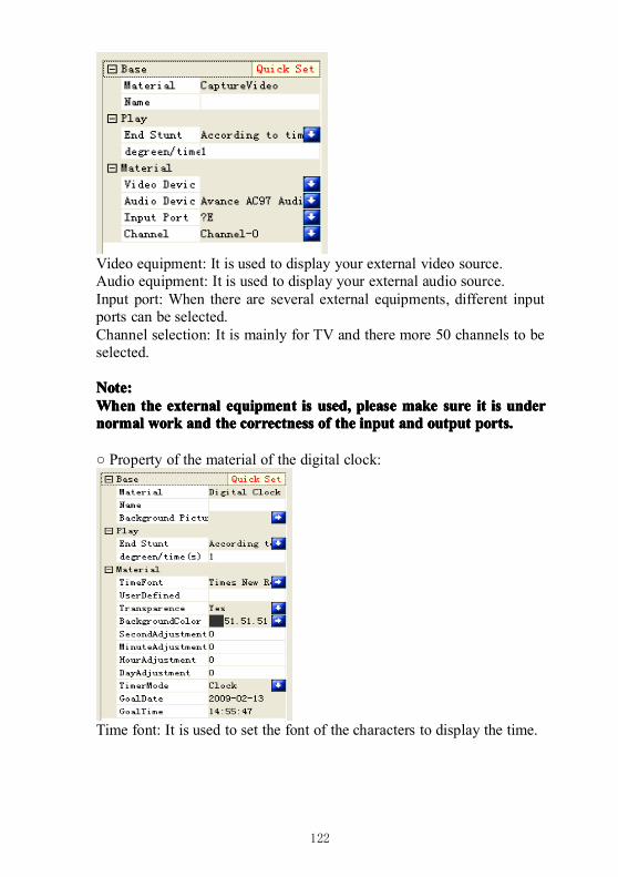
122
Video equipment: It is used to display your external video source.Audio equipment: It is used to display your external audio source.Input port: When there are several external equipments, different inputports can be selected.Channel selection: It is mainly for TV and there more 50 channels to beselected.
Note:Note:Note:Note:WhenWhenWhenWhen thethethethe externalexternalexternalexternal equipmentequipmentequipmentequipment isisisis used,used,used,used, pleasepleasepleaseplease makemakemakemake suresuresuresure itititit isisisis underunderunderundernormalnormalnormalnormal workworkworkwork andandandand thethethethe correctnesscorrectnesscorrectnesscorrectness ofofofof thethethethe inputinputinputinput andandandand outputoutputoutputoutput ports.ports.ports.ports.
○ Property of the material of the digital clock:
Time font: It is used to set the font of the characters to display the time.
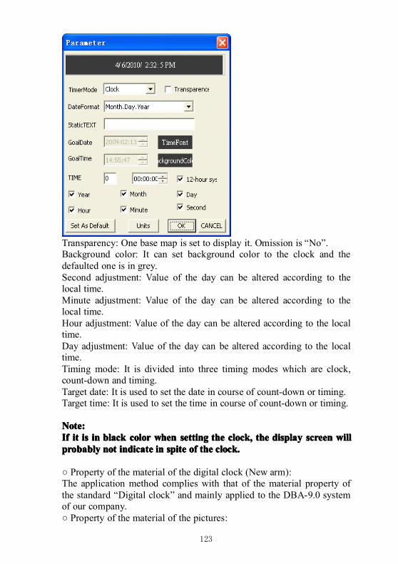
123
Transparency: One base map is set to display it. Omission is “No”.Background color: It can set background color to the clock and thedefaulted one is in grey.Second adjustment: Value of the day can be altered according to thelocal time.Minute adjustment: Value of the day can be altered according to thelocal time.Hour adjustment: Value of the day can be altered according to the localtime.Day adjustment: Value of the day can be altered according to the localtime.Timing mode: It is divided into three timing modes which are clock,count-down and timing.Target date: It is used to set the date in course of count-down or timing.Target time: It is used to set the time in course of count-down or timing.
Note:Note:Note:Note:IfIfIfIf itititit isisisis inininin blackblackblackblack colorcolorcolorcolor whenwhenwhenwhen settingsettingsettingsetting thethethethe clock,clock,clock,clock, thethethethe displaydisplaydisplaydisplay screenscreenscreenscreen willwillwillwillprobablyprobablyprobablyprobably notnotnotnot indicateindicateindicateindicate inininin spitespitespitespite ofofofof thethethethe clock.clock.clock.clock.
○ Property of the material of the digital clock (New arm):The application method complies with that of the material property ofthe standard “Digital clock” and mainly applied to the DBA-9.0 systemof our company.○ Property of the material of the pictures:
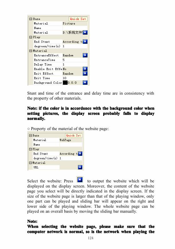
124
Stunt and time of the entrance and delay time are in consistency withthe property of other materials.
Note:Note:Note:Note: ifififif thethethethe colorcolorcolorcolor isisisis inininin accordanceaccordanceaccordanceaccordance withwithwithwith thethethethe backgroundbackgroundbackgroundbackground colorcolorcolorcolor whenwhenwhenwhensettingsettingsettingsetting pictures,pictures,pictures,pictures, thethethethe displaydisplaydisplaydisplay screenscreenscreenscreen probablyprobablyprobablyprobably fallsfallsfallsfalls totototo displaydisplaydisplaydisplaynormally.normally.normally.normally.
○ Property of the material of the website page:
Select the website: Press to output the website which will bedisplayed on the display screen. Moreover, the content of the websitepage you select will be directly indicated in the display screen. If thesize of the website page is larger than that of the playing window, onlyone part can be played and sliding bar will appear on the right andlower side of the playing window. The whole website page can beplayed on an overall basis by moving the sliding bar manually.
Note:Note:Note:Note:WhenWhenWhenWhen selectingselectingselectingselecting thethethethe websitewebsitewebsitewebsite page,page,page,page, pleasepleasepleaseplease makemakemakemake suresuresuresure thatthatthatthat thethethethecomputercomputercomputercomputer networknetworknetworknetwork isisisis normal,normal,normal,normal, sosososo isisisis thethethethe networknetworknetworknetwork whenwhenwhenwhen playingplayingplayingplaying thethethethe
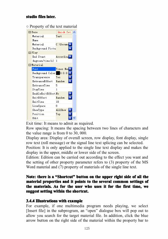
125
studiostudiostudiostudio filesfilesfilesfiles later.later.later.later.
○ Property of the text material
Exit time: It means to admit as required.Row spacing: It means the spacing between two lines of characters andthe value range is from 0 to 30, 000.Display area: Display of overall screen, row display, font display, singlerow text (roll message) or the signal line text splicing can be selected.Position: It is only applied to the single line text display and makes thedisplay in the upper, middle or lower side of the screen.Edition: Edition can be carried out according to the effect you want andthe setting of other property parameter refers to (3) property of the MSWord material and (7) property of materials of the single line text.
Note:Note:Note:Note: theretheretherethere isisisis aaaa ““““SSSShortcuthortcuthortcuthortcut”””” buttonbuttonbuttonbutton onononon thethethethe upperupperupperupper rightrightrightright sidesidesideside ofofofof allallallall thethethethematerialmaterialmaterialmaterial propertiespropertiespropertiesproperties andandandand itititit pointspointspointspoints totototo thethethethe severalseveralseveralseveral commoncommoncommoncommon settingssettingssettingssettings ofofofofthethethethe materials.materials.materials.materials. AsAsAsAs forforforfor thethethethe useruseruseruser whowhowhowho usesusesusesuses itititit forforforfor thethethethe firstfirstfirstfirst time,time,time,time, wewewewesuggestsuggestsuggestsuggest settingsettingsettingsetting withinwithinwithinwithin thethethethe shortcut.shortcut.shortcut.shortcut.
3.4.43.4.43.4.43.4.4 IllustrationsIllustrationsIllustrationsIllustrations withwithwithwith exampleexampleexampleexampleFor example, if one multimedia program needs playing, we select[Insert file] in the subprogram, an “open” dialogue box will pop out toallow you search for the target material file. In addition, click the bluearrow button on the right side of the material within the property bar to
126
look for and change the target material file or right click on thelower side of the [Subwindow] of the project bar; clicking [Selectmaterial file] can also reach the purpose of adding material files.Select the material file you intend to play and click [Open]. Thedialogue box of the multimedia playing software will pop out and thename of the program can be customized within the property bar on theright side. The material file also can carry out automatic adjustment,mute, cycle, display mode, visual effect type, visual effect stunt andremote URL.
Note:Note:Note:Note:WhenWhenWhenWhen [[[[MMMMute]ute]ute]ute] orororor [[[[CCCCycle]ycle]ycle]ycle] isisisis selectedselectedselectedselected asasasas [Yes],[Yes],[Yes],[Yes], pleasepleasepleaseplease setsetsetset [[[[AAAAutomaticutomaticutomaticutomaticadjustment]adjustment]adjustment]adjustment] asasasas [Yes][Yes][Yes][Yes] asasasas well.well.well.well.
Add program to each subwindow one by one and when clicking[Editing], the forward move in the pull-down menu will make theselected subwindow and the content of the program change over the lastsubwindow and the content of the program; in the same way, thebackward move changes with the next subwindow and the content ofthe program.Click the playing button in the tool bar after finishing the work aboveor press the shortcut key F9, the playing file will appear on thecoordinate place of the desktop which has been set. The content ofdifferent subwindows in the same screen will be played at the sametime, if different subwindows are set under the same position, thecontent of the previous subwindow will cover the content of the latersubwindow. The content here is synchronous with that played on theLED display screen.The software supports several playing windows to open the programfiles, play and edit independently at the same time instead ofinfluencing other playing windows.
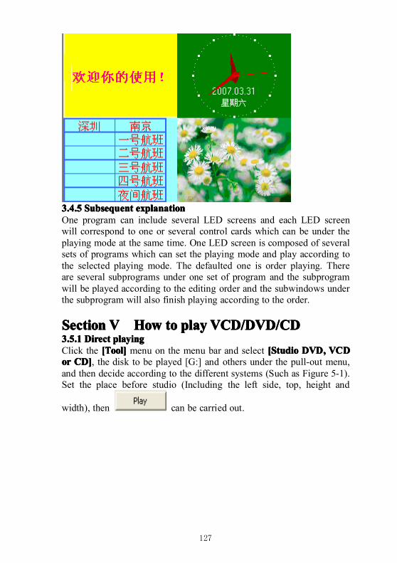
127
3.4.53.4.53.4.53.4.5 SubsequentSubsequentSubsequentSubsequent explanationexplanationexplanationexplanationOne program can include several LED screens and each LED screenwill correspond to one or several control cards which can be under theplaying mode at the same time. One LED screen is composed of severalsets of programs which can set the playing mode and play according tothe selected playing mode. The defaulted one is order playing. Thereare several subprograms under one set of program and the subprogramwill be played according to the editing order and the subwindows underthe subprogram will also finish playing according to the order.
SectionSectionSectionSection VVVV HowHowHowHow totototo playplayplayplay VCD/DVD/VCD/DVD/VCD/DVD/VCD/DVD/CDCDCDCD3.5.13.5.13.5.13.5.1 DirectDirectDirectDirect playingplayingplayingplayingClick the [[[[TTTTool]ool]ool]ool] menu on the menu bar and select [[[[SSSStudiotudiotudiotudio DVD,DVD,DVD,DVD, VCDVCDVCDVCDorororor CD]CD]CD]CD], the disk to be played [G:] and others under the pull-out menu,and then decide according to the different systems (Such as Figure 5-1).Set the place before studio (Including the left side, top, height and
width), then can be carried out.
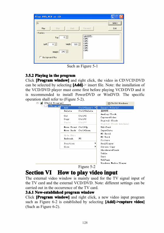
128
Such as Figure 5-1
3.5.23.5.23.5.23.5.2 PlayingPlayingPlayingPlaying inininin thethethethe programprogramprogramprogramClick [[[[PPPProgramrogramrogramrogram window]window]window]window] and right click, the video in CD\VCD\DVDcan be selected by selecting [[[[AAAAdd]dd]dd]dd]-> insert file. Note: the installation ofthe VCD/DVD player must come first before playing VCD/DVD and itis recommended to install PowerDVD or WinDVD. The specificoperation shall refer to (Figure 5-2).
Figure 5-2SectionSectionSectionSection VIVIVIVI HowHowHowHow totototo playplayplayplay videovideovideovideo inputinputinputinputThe external video window is mainly used for the TV signal input ofthe TV card and the external VCD/DVD. Note: different settings can becarried out in the occurrence of the TV card.3.6.13.6.13.6.13.6.1 New-establishedNew-establishedNew-establishedNew-established programprogramprogramprogram windowwindowwindowwindowClick [[[[PPPProgramrogramrogramrogram window]window]window]window] and right click, a new video input programsuch as Figure 6-2 is established by selecting [[[[AAAAdd]->capturedd]->capturedd]->capturedd]->capture video]video]video]video](Such as Figure 6-2).
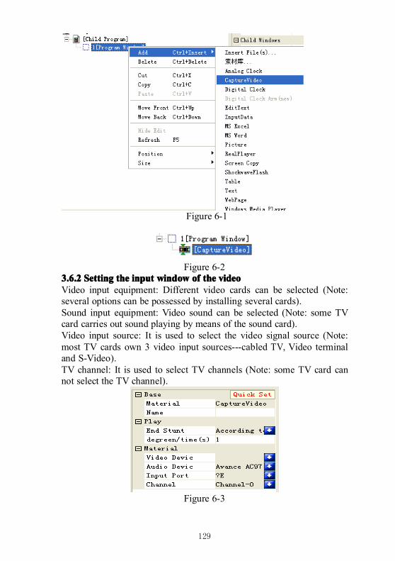
129
Figure 6-1
Figure 6-23.6.23.6.23.6.23.6.2 SettingSettingSettingSetting thethethethe inputinputinputinput windowwindowwindowwindow ofofofof thethethethe videovideovideovideoVideo input equipment: Different video cards can be selected (Note:several options can be possessed by installing several cards).Sound input equipment: Video sound can be selected (Note: some TVcard carries out sound playing by means of the sound card).Video input source: It is used to select the video signal source (Note:most TV cards own 3 video input sources---cabled TV, Video terminaland S-Video).TV channel: It is used to select TV channels (Note: some TV card cannot select the TV channel).
Figure 6-3
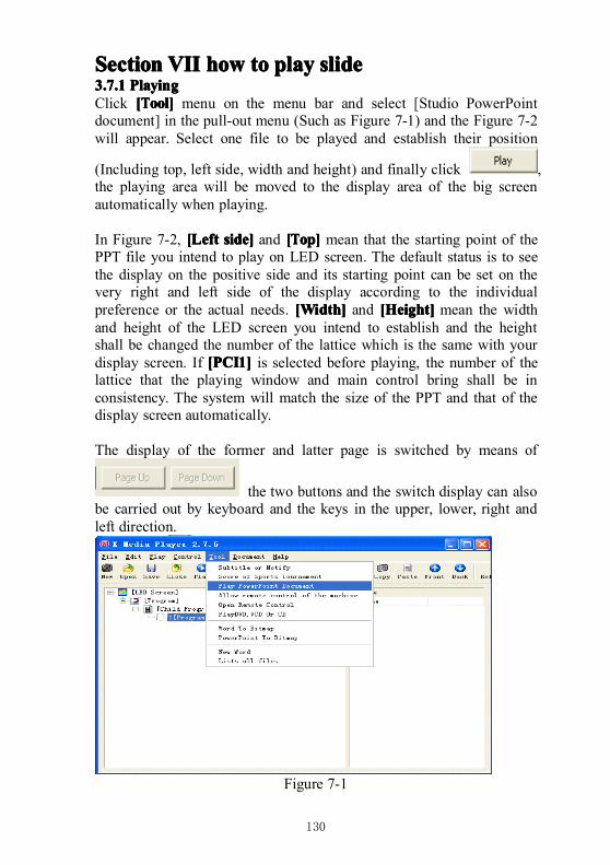
130
SectionSectionSectionSection VIIVIIVIIVII howhowhowhow totototo playplayplayplay slideslideslideslide3.7.13.7.13.7.13.7.1 PlayingPlayingPlayingPlayingClick [[[[TTTTool]ool]ool]ool] menu on the menu bar and select [Studio PowerPointdocument] in the pull-out menu (Such as Figure 7-1) and the Figure 7-2will appear. Select one file to be played and establish their position
(Including top, left side, width and height) and finally click ,the playing area will be moved to the display area of the big screenautomatically when playing.
In Figure 7-2, [[[[LLLLefteftefteft side]side]side]side] and [[[[TTTTop]op]op]op] mean that the starting point of thePPT file you intend to play on LED screen. The default status is to seethe display on the positive side and its starting point can be set on thevery right and left side of the display according to the individualpreference or the actual needs. [Width][Width][Width][Width] and [[[[HHHHeight]eight]eight]eight] mean the widthand height of the LED screen you intend to establish and the heightshall be changed the number of the lattice which is the same with yourdisplay screen. If [PCI1][PCI1][PCI1][PCI1] is selected before playing, the number of thelattice that the playing window and main control bring shall be inconsistency. The system will match the size of the PPT and that of thedisplay screen automatically.
The display of the former and latter page is switched by means of
the two buttons and the switch display can alsobe carried out by keyboard and the keys in the upper, lower, right andleft direction.
Figure 7-1
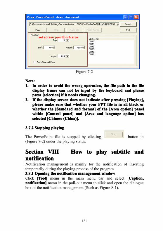
131
Figure 7-2
Note:Note:Note:Note:1.1.1.1. InInInIn orderorderorderorder totototo avoidavoidavoidavoid thethethethe wrongwrongwrongwrong operation,operation,operation,operation, thethethethe filefilefilefile pathpathpathpath inininin thethethethe filefilefilefile
displaydisplaydisplaydisplay frameframeframeframe cancancancan notnotnotnot bebebebe inputinputinputinput bybybyby thethethethe keyboardkeyboardkeyboardkeyboard andandandand pleasepleasepleasepleasepresspresspresspress [selection][selection][selection][selection] ifififif itititit needsneedsneedsneeds changing.changing.changing.changing.
2.2.2.2. IfIfIfIf thethethethe displaydisplaydisplaydisplay screenscreenscreenscreen doesdoesdoesdoes notnotnotnot indicateindicateindicateindicate afterafterafterafter pressingpressingpressingpressing [[[[PPPPlaying],laying],laying],laying],pleasepleasepleaseplease makemakemakemake suresuresuresure thatthatthatthat whetherwhetherwhetherwhether youryouryouryour PPTPPTPPTPPT filefilefilefile isisisis inininin allallallall blackblackblackblack ororororwhetherwhetherwhetherwhether thethethethe [[[[SSSStandardtandardtandardtandard andandandand format]format]format]format] ofofofof thethethethe [[[[AAAArearearearea option]option]option]option] panelpanelpanelpanelwithinwithinwithinwithin [[[[CCCControlontrolontrolontrol panel]panel]panel]panel] andandandand [[[[AAAArearearearea andandandand languagelanguagelanguagelanguage option]option]option]option] hashashashasselectedselectedselectedselected [Chinese[Chinese[Chinese[Chinese (China)].(China)].(China)].(China)].
3.7.23.7.23.7.23.7.2 StoppingStoppingStoppingStopping playingplayingplayingplaying
The PowerPoint file is stopped by clicking button in(Figure 7-2) under the playing status.
SectionSectionSectionSection VIIIVIIIVIIIVIII HowHowHowHow totototo playplayplayplay subtisubtisubtisubtittttlelelele andandandandnotificationnotificationnotificationnotificationNotification management is mainly for the notification of insertingtemporarily during the playing process of the program.3.8.13.8.13.8.13.8.1 OpeningOpeningOpeningOpening thethethethe notificationnotificationnotificationnotification managementmanagementmanagementmanagement windowwindowwindowwindowClick [[[[TTTTool]ool]ool]ool] menu in the main menu bar and select [[[[CCCCaption,aption,aption,aption,notification]notification]notification]notification] menu in the pull-out menu to click and open the dialoguebox of the notification management (Such as Figure 8-1).
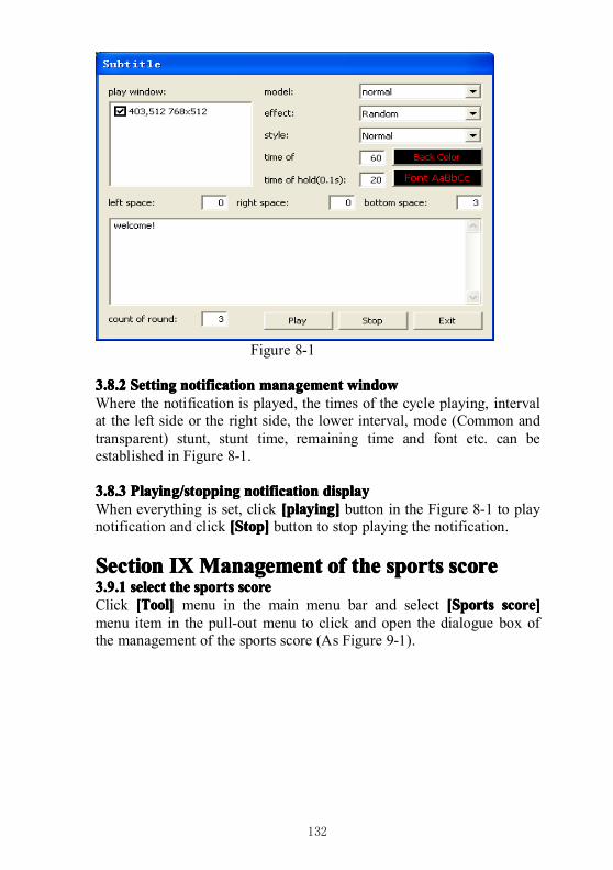
132
Figure 8-1
3.8.23.8.23.8.23.8.2 SettingSettingSettingSetting notificationnotificationnotificationnotification managementmanagementmanagementmanagement windowwindowwindowwindowWhere the notification is played, the times of the cycle playing, intervalat the left side or the right side, the lower interval, mode (Common andtransparent) stunt, stunt time, remaining time and font etc. can beestablished in Figure 8-1.
3.8.33.8.33.8.33.8.3 Playing/stoppingPlaying/stoppingPlaying/stoppingPlaying/stopping notificationnotificationnotificationnotification displaydisplaydisplaydisplayWhen everything is set, click [playing][playing][playing][playing] button in the Figure 8-1 to playnotification and click [[[[SSSStop]top]top]top] button to stop playing the notification.
SectionSectionSectionSection IXIXIXIXManagementManagementManagementManagement ofofofof thethethethe sportssportssportssports scorescorescorescore3.9.13.9.13.9.13.9.1 selectselectselectselect thethethethe sportssportssportssports scorescorescorescoreClick [[[[TTTTool]ool]ool]ool] menu in the main menu bar and select [[[[SSSSportsportsportsports score]score]score]score]menu item in the pull-out menu to click and open the dialogue box ofthe management of the sports score (As Figure 9-1).
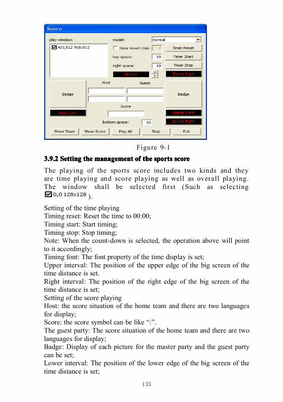
133
Figure 9-1
3.9.23.9.23.9.23.9.2 SettingSettingSettingSetting thethethethe managementmanagementmanagementmanagement ofofofof thethethethe sportssportssportssports scorescorescorescore
The playing of the sports score includes two kinds and theyare time playing and score playing as well as overall playing.The window shall be selected first (Such as selecting
).
Setting of the time playingTiming reset: Reset the time to 00:00;Timing start: Start timing;Timing stop: Stop timing;Note: When the count-down is selected, the operation above will pointto it accordingly;Timing font: The font property of the time display is set;Upper interval: The position of the upper edge of the big screen of thetime distance is set.Right interval: The position of the right edge of the big screen of thetime distance is set;Setting of the score playingHost: the score situation of the home team and there are two languagesfor display;Score: the score symbol can be like “:”.The guest party: The score situation of the home team and there are twolanguages for display;Badge: Display of each picture for the master party and the guest partycan be set;Lower interval: The position of the lower edge of the big screen of thetime distance is set;
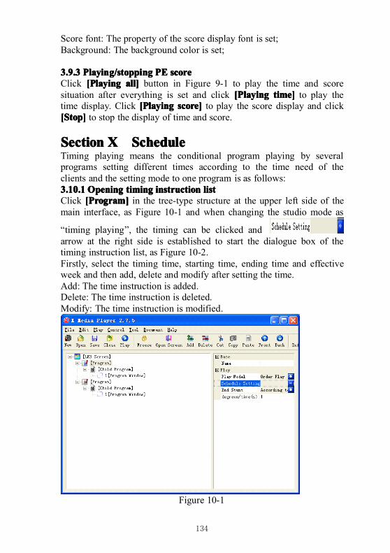
134
Score font: The property of the score display font is set;Background: The background color is set;
3.9.33.9.33.9.33.9.3 Playing/stoppingPlaying/stoppingPlaying/stoppingPlaying/stopping PEPEPEPE scorescorescorescoreClick [[[[PPPPlayinglayinglayinglaying all]all]all]all] button in Figure 9-1 to play the time and scoresituation after everything is set and click [[[[PPPPlayinglayinglayinglaying time]time]time]time] to play thetime display. Click [[[[PPPPlayinglayinglayinglaying score]score]score]score] to play the score display and click[[[[SSSStop]top]top]top] to stop the display of time and score.
SectionSectionSectionSection XXXX SSSSchedulechedulechedulecheduleTiming playing means the conditional program playing by severalprograms setting different times according to the time need of theclients and the setting mode to one program is as follows:3.10.13.10.13.10.13.10.1 OpeningOpeningOpeningOpening timingtimingtimingtiming instructioninstructioninstructioninstruction listlistlistlistClick [[[[PPPProgram]rogram]rogram]rogram] in the tree-type structure at the upper left side of themain interface, as Figure 10-1 and when changing the studio mode as
“timing playing”, the timing can be clicked andarrow at the right side is established to start the dialogue box of thetiming instruction list, as Figure 10-2.Firstly, select the timing time, starting time, ending time and effectiveweek and then add, delete and modify after setting the time.Add: The time instruction is added.Delete: The time instruction is deleted.Modify: The time instruction is modified.
Figure 10-1
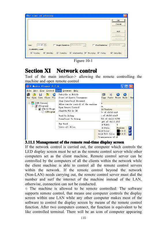
135
Figure 10-1
SectionSectionSectionSection XIXIXIXI NetworkNetworkNetworkNetwork controlcontrolcontrolcontrolTool of the main interface-> allowing the remote controlling themachine and open remote control
3.11.13.11.13.11.13.11.1 ManagementManagementManagementManagement ofofofof thethethethe remoteremoteremoteremote real-timereal-timereal-timereal-time displaydisplaydisplaydisplay screenscreenscreenscreenIf the network control is carried out, the computer which controls theLED display screen must be set as the remote control server while othercomputers set as the client machine. Remote control server can becontrolled by the computers of all the clients within the network whilethe client machine is able to control all the remote control serverswithin the network. If the remote control beyond the network(Non-LAN) needs carrying out, the remote control server must dial thenumber and surf the internet of the machine instead of the LAN,otherwise, connection can not be conducted.○ The machine is allowed to be remote controlled: The softwaresupports remote control, that means one computer controls the displayscreen within one LAN while any other computer makes most of thesoftware to control the display screen by means of the remote controlfunction. After two computers connect, the function is equivalent to belike controlled terminal. There will be an icon of computer appearing
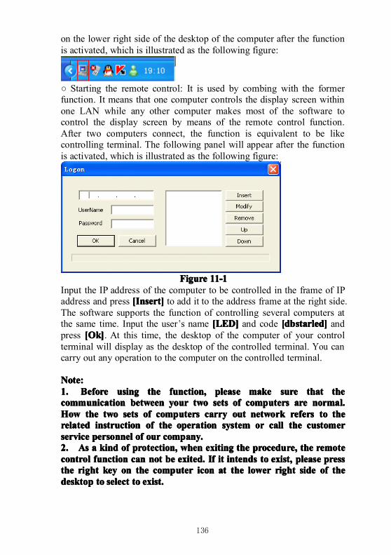
136
on the lower right side of the desktop of the computer after the functionis activated, which is illustrated as the following figure:
○ Starting the remote control: It is used by combing with the formerfunction. It means that one computer controls the display screen withinone LAN while any other computer makes most of the software tocontrol the display screen by means of the remote control function.After two computers connect, the function is equivalent to be likecontrolling terminal. The following panel will appear after the functionis activated, which is illustrated as the following figure:
FigureFigureFigureFigure 11-111-111-111-1Input the IP address of the computer to be controlled in the frame of IPaddress and press [[[[IIIInsert]nsert]nsert]nsert] to add it to the address frame at the right side.The software supports the function of controlling several computers atthe same time. Input the user’s name [LED][LED][LED][LED] and code [[[[dbdbdbdbstarled]starled]starled]starled] andpress [[[[OOOOk]k]k]k]. At this time, the desktop of the computer of your controlterminal will display as the desktop of the controlled terminal. You cancarry out any operation to the computer on the controlled terminal.
Note:Note:Note:Note:1.1.1.1. BeforeBeforeBeforeBefore usingusingusingusing thethethethe function,function,function,function, pleasepleasepleaseplease makemakemakemake suresuresuresure thatthatthatthat thethethethecommunicationcommunicationcommunicationcommunication betweenbetweenbetweenbetween youryouryouryour twotwotwotwo setssetssetssets ofofofof computerscomputerscomputerscomputers areareareare normal.normal.normal.normal.HowHowHowHow thethethethe twotwotwotwo setssetssetssets ofofofof computerscomputerscomputerscomputers carrycarrycarrycarry outoutoutout networknetworknetworknetwork refersrefersrefersrefers totototo thethethetherelatedrelatedrelatedrelated instructioninstructioninstructioninstruction ofofofof thethethethe operationoperationoperationoperation systemsystemsystemsystem orororor callcallcallcall thethethethe customercustomercustomercustomerserviceserviceserviceservice personnelpersonnelpersonnelpersonnel ofofofof ourourourour company.company.company.company.2.2.2.2. AsAsAsAs aaaa kindkindkindkind ofofofof protection,protection,protection,protection, whenwhenwhenwhen exitingexitingexitingexiting thethethethe procedure,procedure,procedure,procedure, thethethethe remoteremoteremoteremotecontrolcontrolcontrolcontrol functionfunctionfunctionfunction cancancancan notnotnotnot bebebebe exited.exited.exited.exited. IfIfIfIf itititit intendsintendsintendsintends totototo exist,exist,exist,exist, pleasepleasepleaseplease presspresspresspressthethethethe rightrightrightright keykeykeykey onononon thethethethe computercomputercomputercomputer iconiconiconicon atatatat thethethethe lowerlowerlowerlower rightrightrightright sidesidesideside ofofofof thethethethedesktopdesktopdesktopdesktop totototo selectselectselectselect totototo exist.exist.exist.exist.
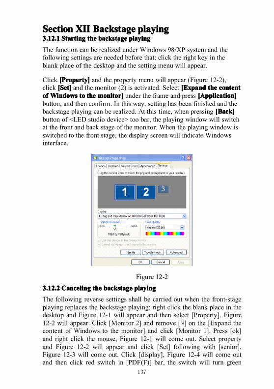
137
SectionSectionSectionSection XIIXIIXIIXII BackstageBackstageBackstageBackstage playingplayingplayingplaying3.12.13.12.13.12.13.12.1 StartingStartingStartingStarting thethethethe backstagebackstagebackstagebackstage playingplayingplayingplaying
The function can be realized under Windows 98/XP system and thefollowing settings are needed before that: click the right key in theblank place of the desktop and the setting menu will appear.
Click [[[[PPPProperty]roperty]roperty]roperty] and the property menu will appear (Figure 12-2),click [[[[SSSSet]et]et]et] and the monitor (2) is activated. Select [[[[EEEExpandxpandxpandxpand thethethethe contentcontentcontentcontentofofofof WindowsWindowsWindowsWindows totototo thethethethe monitor]monitor]monitor]monitor] under the frame and press [[[[AAAApplication]pplication]pplication]pplication]button, and then confirm. In this way, setting has been finished and thebackstage playing can be realized. At this time, when pressing [[[[BBBBack]ack]ack]ack]button of <LED studio device> too bar, the playing window will switchat the front and back stage of the monitor. When the playing window isswitched to the front stage, the display screen will indicate Windowsinterface.
Figure 12-2
3.12.23.12.23.12.23.12.2 CancelingCancelingCancelingCanceling thethethethe backstagebackstagebackstagebackstage playingplayingplayingplaying
The following reverse settings shall be carried out when the front-stageplaying replaces the backstage playing: right click the blank place in thedesktop and Figure 12-1 will appear and then select [Property], Figure12-2 will appear. Click [Monitor 2] and remove [√] on the [Expand thecontent of Windows to the monitor] and click [Monitor 1]. Press [ok]and right click the mouse, Figure 12-1 will come out. Select propertyand Figure 12-2 will appear and click [Set] following with [senior],Figure 12-3 will come out. Click [display], Figure 12-4 will come outand then click red switch in [PDF(F)] bar, the switch will turn green
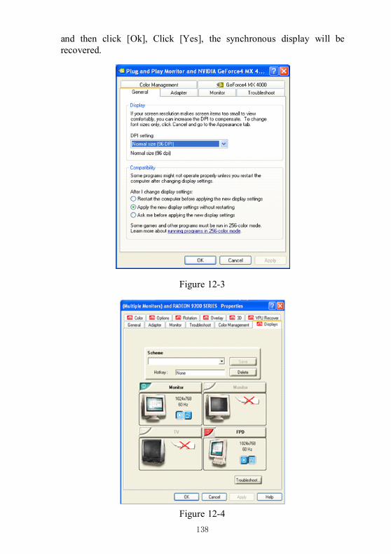
138
and then click [Ok], Click [Yes], the synchronous display will berecovered.
Figure 12-3
Figure 12-4
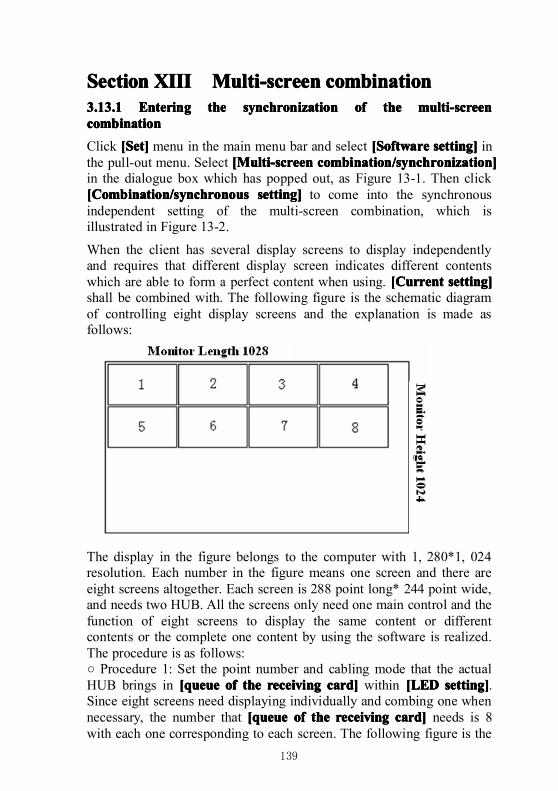
139
SectionSectionSectionSection XIIIXIIIXIIIXIII Multi-screenMulti-screenMulti-screenMulti-screen combinationcombinationcombinationcombination3.13.13.13.13.13.13.13.1 EnteringEnteringEnteringEntering thethethethe synchronizationsynchronizationsynchronizationsynchronization ofofofof thethethethe multi-screenmulti-screenmulti-screenmulti-screencombinationcombinationcombinationcombination
Click [[[[SSSSet]et]et]et] menu in the main menu bar and select [[[[SSSSoftwareoftwareoftwareoftware setting]setting]setting]setting] inthe pull-out menu. Select [[[[MMMMulti-screenulti-screenulti-screenulti-screen combination/synchronization]combination/synchronization]combination/synchronization]combination/synchronization]in the dialogue box which has popped out, as Figure 13-1. Then click[[[[CCCCombination/synchronousombination/synchronousombination/synchronousombination/synchronous setting]setting]setting]setting] to come into the synchronousindependent setting of the multi-screen combination, which isillustrated in Figure 13-2.
When the client has several display screens to display independentlyand requires that different display screen indicates different contentswhich are able to form a perfect content when using. [Current[Current[Current[Current setting]setting]setting]setting]shall be combined with. The following figure is the schematic diagramof controlling eight display screens and the explanation is made asfollows:
The display in the figure belongs to the computer with 1, 280*1, 024resolution. Each number in the figure means one screen and there areeight screens altogether. Each screen is 288 point long* 244 point wide,and needs two HUB. All the screens only need one main control and thefunction of eight screens to display the same content or differentcontents or the complete one content by using the software is realized.The procedure is as follows:○ Procedure 1: Set the point number and cabling mode that the actualHUB brings in [queue[queue[queue[queue ofofofof thethethethe receivingreceivingreceivingreceiving card]card]card]card] within [LED[LED[LED[LED setting]setting]setting]setting].Since eight screens need displaying individually and combing one whennecessary, the number that [queue[queue[queue[queue ofofofof thethethethe receivingreceivingreceivingreceiving card]card]card]card] needs is 8with each one corresponding to each screen. The following figure is the
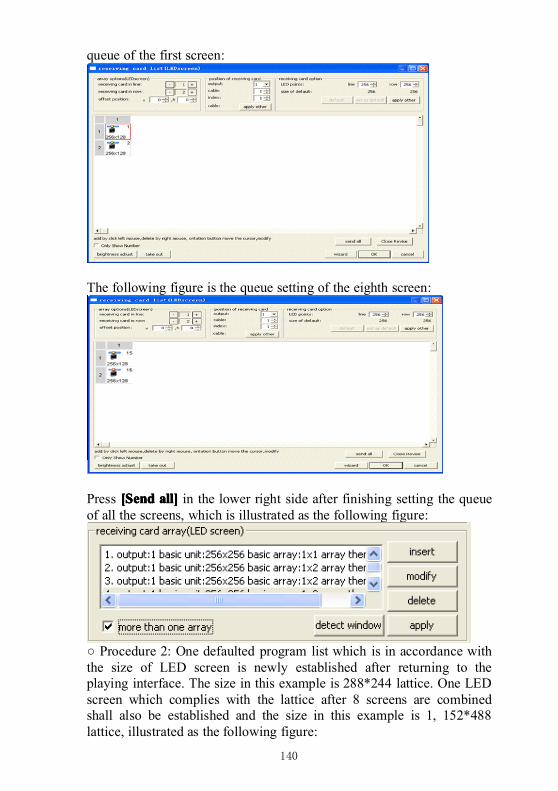
140
queue of the first screen:
The following figure is the queue setting of the eighth screen:
Press [[[[SSSSendendendend all]all]all]all] in the lower right side after finishing setting the queueof all the screens, which is illustrated as the following figure:
○ Procedure 2: One defaulted program list which is in accordance withthe size of LED screen is newly established after returning to theplaying interface. The size in this example is 288*244 lattice. One LEDscreen which complies with the lattice after 8 screens are combinedshall also be established and the size in this example is 1, 152*488lattice, illustrated as the following figure:
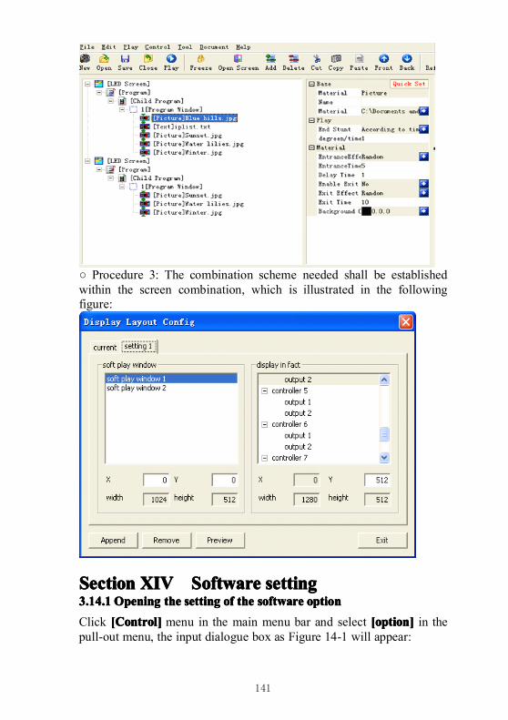
141
○ Procedure 3: The combination scheme needed shall be establishedwithin the screen combination, which is illustrated in the followingfigure:
SectionSectionSectionSection XIVXIVXIVXIV SSSSoftwareoftwareoftwareoftware settingsettingsettingsetting3.14.13.14.13.14.13.14.1 OpeningOpeningOpeningOpening thethethethe settingsettingsettingsetting ofofofof thethethethe softwaresoftwaresoftwaresoftware optionoptionoptionoption
Click [[[[CCCControl]ontrol]ontrol]ontrol] menu in the main menu bar and select [option][option][option][option] in thepull-out menu, the input dialogue box as Figure 14-1 will appear:
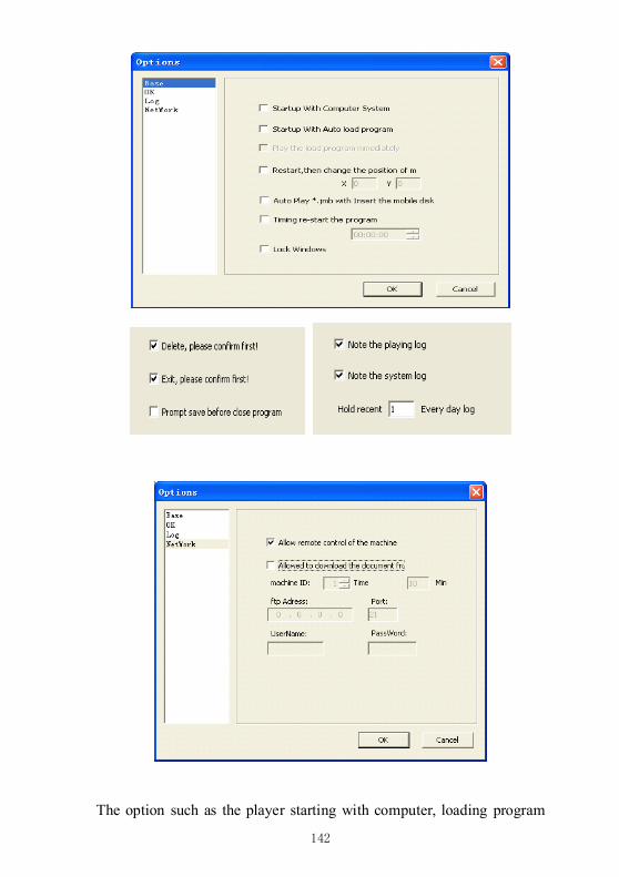
142
The option such as the player starting with computer, loading program
143
list automatically when starting, changing the position of the mousewhen starting, confirming when delete/exit, hint to save when closingthe program list, the position of the mouse, studio from U disk, memorystudio/system log and log reservation can be selected.
Note:Note:Note:Note:TheTheTheThe loglogloglog filefilefilefile isisisis savedsavedsavedsaved underunderunderunder xmplayer\logxmplayer\logxmplayer\logxmplayer\log catalogcatalogcatalogcatalog ofofofof thethethethe systemsystemsystemsystem withwithwithwith[*.[*.[*.[*. TXT]TXT]TXT]TXT] formatformatformatformat andandandand thethethethe softwaresoftwaresoftwaresoftware willwillwillwill startstartstartstart automaticallyautomaticallyautomaticallyautomatically whenwhenwhenwhen thethethethesoftwaresoftwaresoftwaresoftware encountersencountersencountersencounters faults:faults:faults:faults: thethethethe softwaresoftwaresoftwaresoftware willwillwillwill startstartstartstart automaticallyautomaticallyautomaticallyautomaticallywhenwhenwhenwhen encounteringencounteringencounteringencountering faultsfaultsfaultsfaults andandandand exiting.exiting.exiting.exiting.TimingTimingTimingTiming restartrestartrestartrestart system:system:system:system: thethethethe softwaresoftwaresoftwaresoftware isisisis startedstartedstartedstarted againagainagainagain inininin thethethethe setsetsetset time.time.time.time.ConfirmConfirmConfirmConfirm whenwhenwhenwhen exiting:exiting:exiting:exiting: thethethethe softwaresoftwaresoftwaresoftware willwillwillwill appearappearappearappear hinthinthinthint dialoguedialoguedialoguedialogue boxboxboxboxwhenwhenwhenwhen exitingexitingexitingexiting forforforfor eacheacheacheach time.time.time.time.
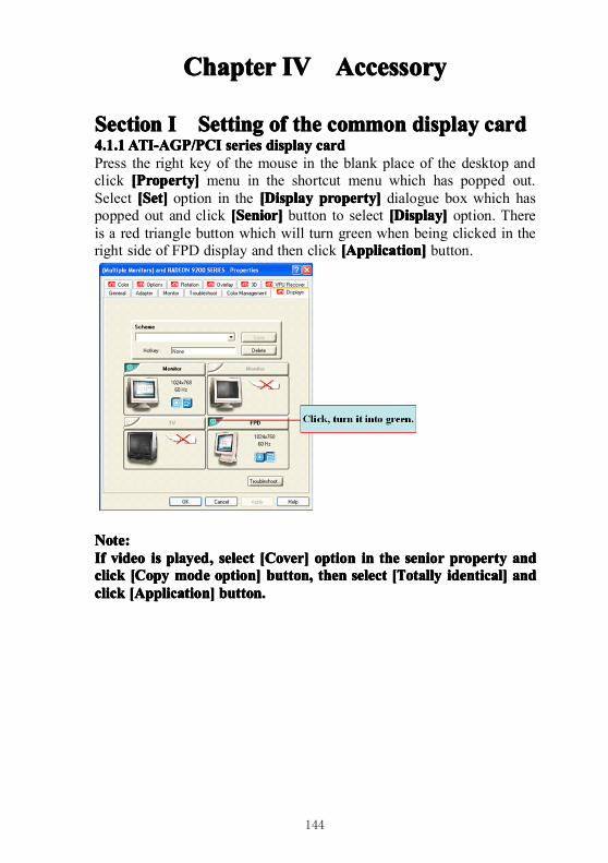
144
ChapterChapterChapterChapter IVIVIVIV AccessoryAccessoryAccessoryAccessory
SectionSectionSectionSection IIII SettingSettingSettingSetting ofofofof thethethethe commoncommoncommoncommon displaydisplaydisplaydisplay cardcardcardcard4.1.14.1.14.1.14.1.1ATI-AGP/PCIATI-AGP/PCIATI-AGP/PCIATI-AGP/PCI seriesseriesseriesseries displaydisplaydisplaydisplay cardcardcardcardPress the right key of the mouse in the blank place of the desktop andclick [[[[PPPProperty]roperty]roperty]roperty] menu in the shortcut menu which has popped out.Select [[[[SSSSet]et]et]et] option in the [[[[DDDDisplayisplayisplayisplay property]property]property]property] dialogue box which haspopped out and click [[[[SSSSenior]enior]enior]enior] button to select [[[[DDDDisplay]isplay]isplay]isplay] option. Thereis a red triangle button which will turn green when being clicked in theright side of FPD display and then click [[[[AAAApplication]pplication]pplication]pplication] button.
Note:Note:Note:Note:IfIfIfIf videovideovideovideo isisisis playedplayedplayedplayed,,,, selectselectselectselect [[[[CCCCover]over]over]over] optionoptionoptionoption inininin thethethethe seniorseniorseniorsenior propertypropertypropertyproperty andandandandclickclickclickclick [[[[CCCCopyopyopyopy modemodemodemode option]option]option]option] button,button,button,button, thenthenthenthen selectselectselectselect [[[[TTTTotallyotallyotallyotally identical]identical]identical]identical] andandandandclickclickclickclick [[[[AAAApplication]pplication]pplication]pplication] button.button.button.button.
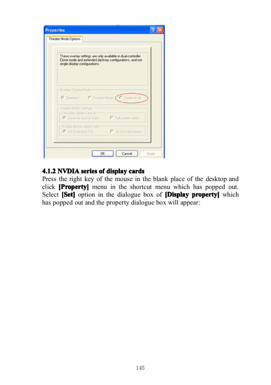
145
4.1.24.1.24.1.24.1.2 NVDIANVDIANVDIANVDIA seriesseriesseriesseries ofofofof displaydisplaydisplaydisplay cardscardscardscardsPress the right key of the mouse in the blank place of the desktop andclick [[[[PPPProperty]roperty]roperty]roperty] menu in the shortcut menu which has popped out.Select [[[[SSSSet]et]et]et] option in the dialogue box of [[[[DDDDisplayisplayisplayisplay property]property]property]property] whichhas popped out and the property dialogue box will appear:
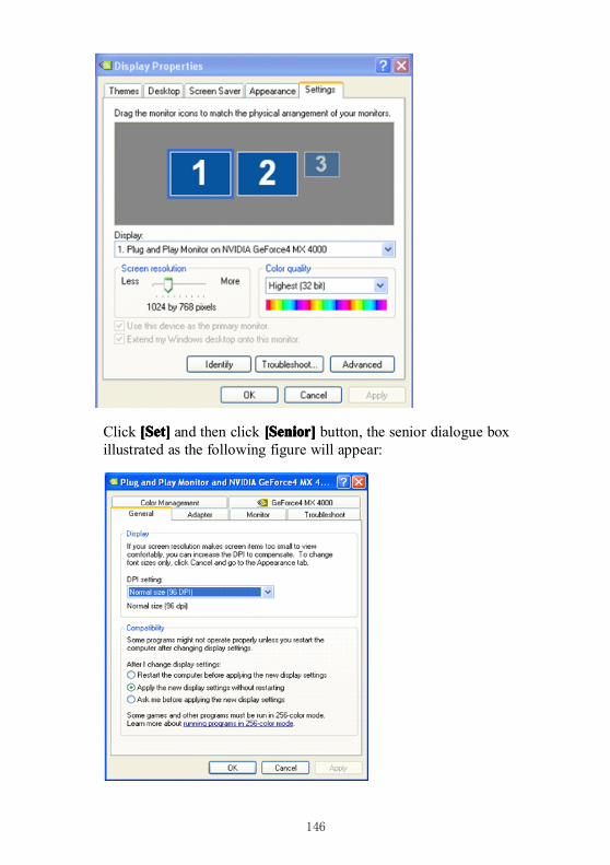
146
Click [[[[SSSSet]et]et]et] and then click [[[[SSSSenior]enior]enior]enior] button, the senior dialogue boxillustrated as the following figure will appear:
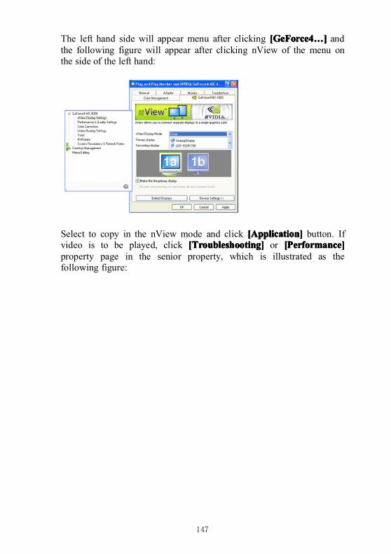
147
The left hand side will appear menu after clicking [GeForce4[GeForce4[GeForce4[GeForce4…………]]]] andthe following figure will appear after clicking nView of the menu onthe side of the left hand:
Select to copy in the nView mode and click [[[[AAAApplication]pplication]pplication]pplication] button. Ifvideo is to be played, click [[[[TTTTroubleshooting]roubleshooting]roubleshooting]roubleshooting] or [[[[PPPPerformance]erformance]erformance]erformance]property page in the senior property, which is illustrated as thefollowing figure:
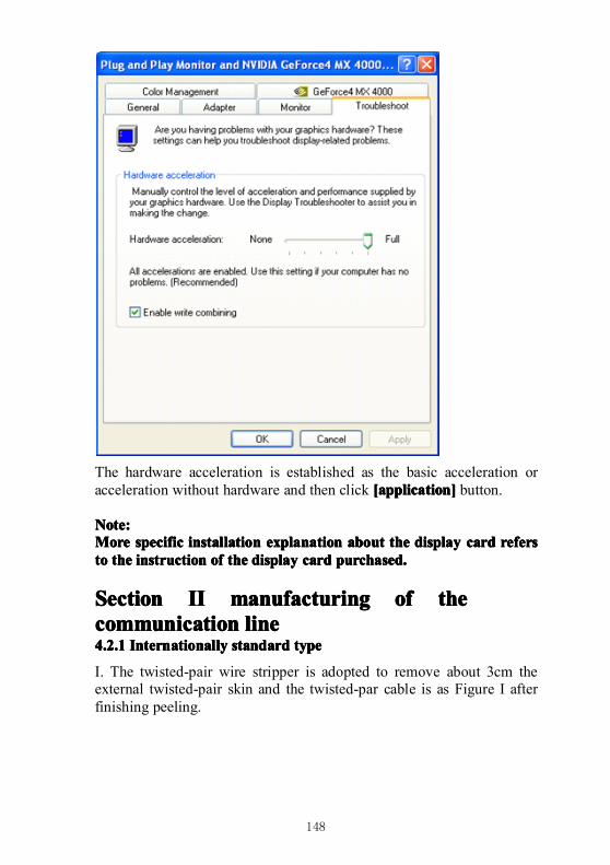
148
The hardware acceleration is established as the basic acceleration oracceleration without hardware and then click [application][application][application][application] button.
Note:Note:Note:Note:MoreMoreMoreMore specificspecificspecificspecific installationinstallationinstallationinstallation explanationexplanationexplanationexplanation aboutaboutaboutabout thethethethe displaydisplaydisplaydisplay cardcardcardcard refersrefersrefersreferstotototo thethethethe instructioninstructioninstructioninstruction ofofofof thethethethe displaydisplaydisplaydisplay cardcardcardcard purchased.purchased.purchased.purchased.
SectionSectionSectionSection IIIIIIII manufacturingmanufacturingmanufacturingmanufacturing ofofofof thethethethecommunicationcommunicationcommunicationcommunication linelinelineline4.2.14.2.14.2.14.2.1 InternationallyInternationallyInternationallyInternationally standardstandardstandardstandard typetypetypetype
I. The twisted-pair wire stripper is adopted to remove about 3cm theexternal twisted-pair skin and the twisted-par cable is as Figure I afterfinishing peeling.
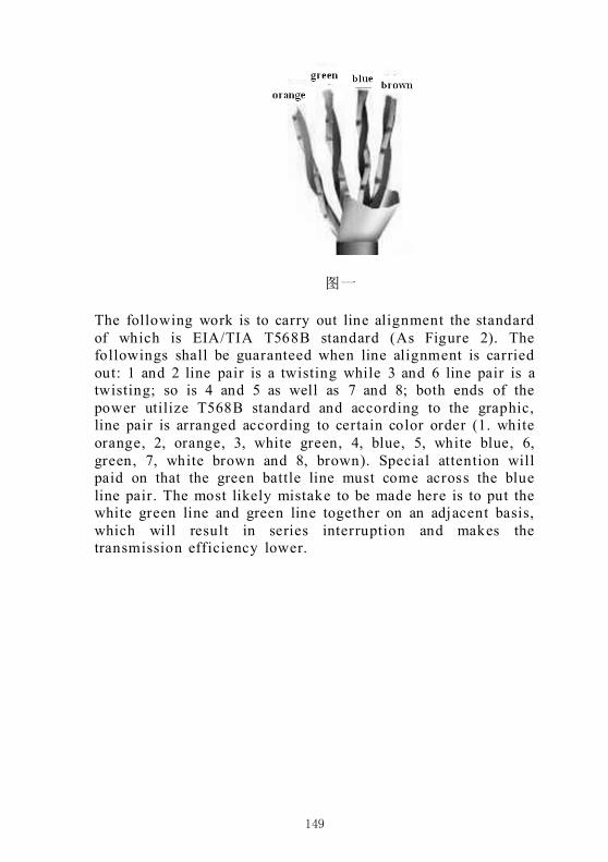
149
图一
The following work is to carry out line alignment the standardof which is EIA/TIA T568B standard (As Figure 2). Thefollowings shall be guaranteed when line alignment is carriedout: 1 and 2 line pair is a twisting while 3 and 6 line pair is atwisting; so is 4 and 5 as well as 7 and 8; both ends of thepower utilize T568B standard and according to the graphic,line pair is arranged according to certain color order (1. whiteorange, 2, orange, 3, white green, 4, blue, 5, white blue, 6,green, 7, white brown and 8, brown). Special attention willpaid on that the green battle line must come across the blueline pair. The most likely mistake to be made here is to put thewhite green line and green line together on an adjacent basis,which will result in series interruption and makes thetransmission efficiency lower.
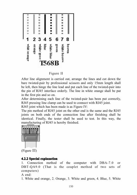
150
Figure II
After line alignment is carried out, arrange the lines and cut down thebare twisted-pair by professional scissors and only 15mm length shallbe left, then hinge the line lead and put each line of the twisted-pair intothe pin of RJ45 interface orderly. The line in white orange shall be putin the first pin and so on.After determining each line of the twisted-pair has been put correctly,RJ45 pressing line clamp can be used to connect with RJ45 joint.RJ45 joint which has been made is as Figure IV:The pin method of RJ45 joint on the other end is the same and the RJ45joints on both ends of the connection line after finishing shall beidentical. Finally, the tester shall be used to test. In this way, themanufacturing of RJ45 is hereby finished.
(Figure Ⅲ)
4.2.24.2.24.2.24.2.2 SpecialSpecialSpecialSpecial explanationexplanationexplanationexplanation1. Connection method of the computer with DBA-7.0 orDBT-QA9.0 (That is the couplet method of two sets ofcomputers)A end:1. White and orange, 2. Orange, 3. White and green, 4. Blue, 5. White
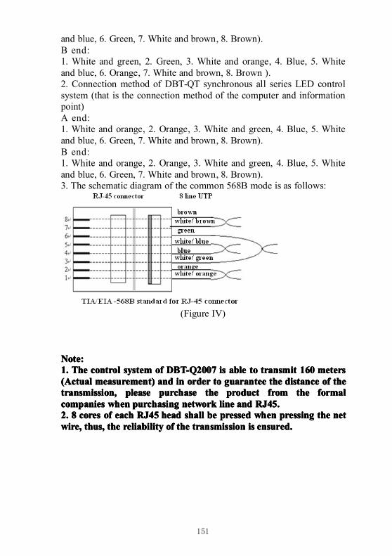
151
and blue, 6. Green, 7. White and brown, 8. Brown).B end:1. White and green, 2. Green, 3. White and orange, 4. Blue, 5. Whiteand blue, 6. Orange, 7. White and brown, 8. Brown ).2. Connection method of DBT-QT synchronous all series LED controlsystem (that is the connection method of the computer and informationpoint)A end:1. White and orange, 2. Orange, 3. White and green, 4. Blue, 5. Whiteand blue, 6. Green, 7. White and brown, 8. Brown).B end:1. White and orange, 2. Orange, 3. White and green, 4. Blue, 5. Whiteand blue, 6. Green, 7. White and brown, 8. Brown).3. The schematic diagram of the common 568B mode is as follows:
(Figure IV)
Note:Note:Note:Note:1.1.1.1. TheTheTheThe controlcontrolcontrolcontrol systemsystemsystemsystem ofofofof DBT-Q2007DBT-Q2007DBT-Q2007DBT-Q2007 isisisis ableableableable totototo transmittransmittransmittransmit 160160160160 metersmetersmetersmeters((((AAAActualctualctualctual measurement)measurement)measurement)measurement) andandandand inininin orderorderorderorder totototo guaranteeguaranteeguaranteeguarantee thethethethe distancedistancedistancedistance ofofofof thethethethetransmission,transmission,transmission,transmission, pleasepleasepleaseplease purchasepurchasepurchasepurchase thethethethe productproductproductproduct fromfromfromfrom thethethethe formalformalformalformalcompaniescompaniescompaniescompanies whenwhenwhenwhen purchasingpurchasingpurchasingpurchasing networknetworknetworknetwork linelinelineline andandandand RJ45.RJ45.RJ45.RJ45.2.2.2.2. 8888 corescorescorescores ofofofof eacheacheacheach RJ45RJ45RJ45RJ45 headheadheadhead shallshallshallshall bebebebe pressedpressedpressedpressed whenwhenwhenwhen pressingpressingpressingpressing thethethethe netnetnetnetwire,wire,wire,wire, thus,thus,thus,thus, thethethethe reliabilityreliabilityreliabilityreliability ofofofof thethethethe transmissiontransmissiontransmissiontransmission isisisis ensured.ensured.ensured.ensured.
152
ChapterChapterChapterChapterVVVVCommonCommonCommonCommon pppproblemsroblemsroblemsroblems
SectionSectionSectionSection IIII SynchronousSynchronousSynchronousSynchronous controlcontrolcontrolcontrol systemsystemsystemsystem5.1.15.1.15.1.15.1.1 InterruptionInterruptionInterruptionInterruption ofofofof thethethethe connectionconnectionconnectionconnectionThe specific representation is:① Unsuccessful parameter sending and [connection[connection[connection[connection interruption]interruption]interruption]interruption] willbe suggested;② Failure to find the control card;③ The interface of the software fails to adjust, which means under graystatus. The software [LED[LED[LED[LED controlcontrolcontrolcontrol equipmentequipmentequipmentequipment list]list]list]list] has no main controlicon.Methods used to probably solve problems:① Pull in and out of USB wire again;② Change USB wire;③ The equipment manger checks the equipment connection;④ The computer is confirmed without virus;⑤ If it is under internal type, it is probably due to the loose slot or dirtypart of PCI. Please insert again or adopt the rubber to wipe the PCIinterface.
5.1.25.1.25.1.25.1.2 No-signalNo-signalNo-signalNo-signal outputoutputoutputoutputThe specific representation is:The pilot lamp in the net mouth of the control card is not bright.Methods used to probably solve problems:1. [XMPLAYER][XMPLAYER][XMPLAYER][XMPLAYER] of our company has not been installed and please
determine to install.2. Failure to open the FPD of the display card. Right click my
computer on the desktop-> property-> setting-> senior-> display->FPD.
3. Incorrect resolution mode:The specific representation is: the screen flashes or underuncontrollable status.Troubleshooting method:Adjust the current resolution of the computer to be in accordance withthat of the control card. The product does not totally support severalnon-standard modes such as 1, 152*800. Please contact with thecustomer service department of our company in any specialrequirements.
SectionSectionSectionSection IIIIIIII AsynchronousAsynchronousAsynchronousAsynchronous ccccontrolontrolontrolontrol ssssystemystemystemystem
153
5.2.15.2.15.2.15.2.1 FailureFailureFailureFailure totototo startstartstartstart normallynormallynormallynormallyOpen the power of the control card; the pilot lamp of the power<LED8>, <LED5> and <LED1> are bright successively; if the networkis correctly connected, the pilot lamp of the network communicationwill be bright. If either <LED1> or <LED5> is not bright, it meansfailing to start normally and 1 minute power failure is needed to startagain.
5.2.25.2.25.2.25.2.2 FailureFailureFailureFailure totototo sendsendsendsend thethethethe contentcontentcontentcontent normallynormallynormallynormally1. It will be invalid to send the content under the circumstance withoutthe establishment of the connection and operation can be carried outafter the connection is established.2. Whether the control card connects the power.3. Whether the setting of the IP address of the computer is in conflictwith the control card.4. Try to connect again after closing other procedures.5. When the inspection above has no problems; the damage of the netmouth of the control card or incorrect connection of the net wire can betaken into consideration.6. Whether the IP address of the computer is correct or not. Please referto IP setting.7. Make sure whether the system status LED1 of the control card andthe pilot lamp are bright; if regular flash occurs, please close the powerfor 2 minutes and then repeat the connection procedure above;8. The network connection is normal but the software fails to detect thecontrol card. DBA-9.0 is started manually.9. Colorful screen of the walking wizard, DBA-9.0 is restarted afterpower failure for 1 minute and wizard is carried out again.