User Manual SLTrailer English
40
TK 41040-2-OP (Rev. 12, 08/06) English SL-100e w/TGVI, SL-200e w/TGVI, SL-400e w/SR-2 and Spectrum SL w/μP-IV
-
Upload
athosschiavone -
Category
Documents
-
view
112 -
download
3
Transcript of User Manual SLTrailer English
TK 41040-2-OP (Rev. 12, 08/06)
English
SL-100e w/TGVI, SL-200e w/TGVI,SL-400e w/SR-2 and Spectrum SL w/μP-IV

3
TABLE OF CONTENTS
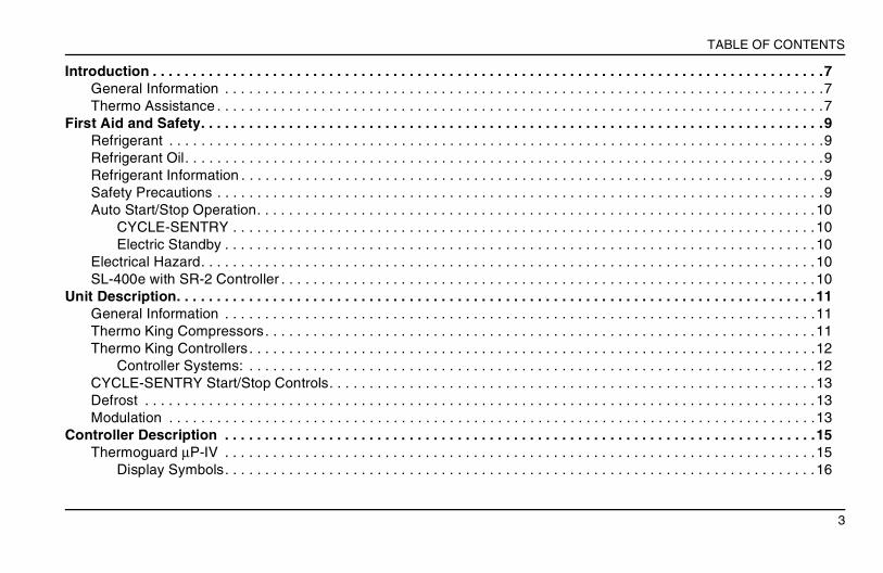
Introduction . . . . . . . . . . . . . . . . . . . . . . . . . . . . . . . . . . . . . . . . . . . . . . . . . . . . . . . . . . . . . . . . . . . . . . . . . . . . . . . . . . . .7General Information . . . . . . . . . . . . . . . . . . . . . . . . . . . . . . . . . . . . . . . . . . . . . . . . . . . . . . . . . . . . . . . . . . . . . . . . . . .7Thermo Assistance . . . . . . . . . . . . . . . . . . . . . . . . . . . . . . . . . . . . . . . . . . . . . . . . . . . . . . . . . . . . . . . . . . . . . . . . . . . .7
First Aid and Safety. . . . . . . . . . . . . . . . . . . . . . . . . . . . . . . . . . . . . . . . . . . . . . . . . . . . . . . . . . . . . . . . . . . . . . . . . . . . . .9Refrigerant . . . . . . . . . . . . . . . . . . . . . . . . . . . . . . . . . . . . . . . . . . . . . . . . . . . . . . . . . . . . . . . . . . . . . . . . . . . . . . . . . .9Refrigerant Oil. . . . . . . . . . . . . . . . . . . . . . . . . . . . . . . . . . . . . . . . . . . . . . . . . . . . . . . . . . . . . . . . . . . . . . . . . . . . . . . .9Refrigerant Information . . . . . . . . . . . . . . . . . . . . . . . . . . . . . . . . . . . . . . . . . . . . . . . . . . . . . . . . . . . . . . . . . . . . . . . . .9Safety Precautions . . . . . . . . . . . . . . . . . . . . . . . . . . . . . . . . . . . . . . . . . . . . . . . . . . . . . . . . . . . . . . . . . . . . . . . . . . . .9Auto Start/Stop Operation. . . . . . . . . . . . . . . . . . . . . . . . . . . . . . . . . . . . . . . . . . . . . . . . . . . . . . . . . . . . . . . . . . . . . .10
CYCLE-SENTRY . . . . . . . . . . . . . . . . . . . . . . . . . . . . . . . . . . . . . . . . . . . . . . . . . . . . . . . . . . . . . . . . . . . . . . . . .10Electric Standby . . . . . . . . . . . . . . . . . . . . . . . . . . . . . . . . . . . . . . . . . . . . . . . . . . . . . . . . . . . . . . . . . . . . . . . . . .10
Electrical Hazard. . . . . . . . . . . . . . . . . . . . . . . . . . . . . . . . . . . . . . . . . . . . . . . . . . . . . . . . . . . . . . . . . . . . . . . . . . . . .10SL-400e with SR-2 Controller . . . . . . . . . . . . . . . . . . . . . . . . . . . . . . . . . . . . . . . . . . . . . . . . . . . . . . . . . . . . . . . . . . .10
Unit Description. . . . . . . . . . . . . . . . . . . . . . . . . . . . . . . . . . . . . . . . . . . . . . . . . . . . . . . . . . . . . . . . . . . . . . . . . . . . . . . .11General Information . . . . . . . . . . . . . . . . . . . . . . . . . . . . . . . . . . . . . . . . . . . . . . . . . . . . . . . . . . . . . . . . . . . . . . . . . .11Thermo King Compressors. . . . . . . . . . . . . . . . . . . . . . . . . . . . . . . . . . . . . . . . . . . . . . . . . . . . . . . . . . . . . . . . . . . . .11Thermo King Controllers . . . . . . . . . . . . . . . . . . . . . . . . . . . . . . . . . . . . . . . . . . . . . . . . . . . . . . . . . . . . . . . . . . . . . . .12
Controller Systems: . . . . . . . . . . . . . . . . . . . . . . . . . . . . . . . . . . . . . . . . . . . . . . . . . . . . . . . . . . . . . . . . . . . . . . .12CYCLE-SENTRY Start/Stop Controls. . . . . . . . . . . . . . . . . . . . . . . . . . . . . . . . . . . . . . . . . . . . . . . . . . . . . . . . . . . . .13Defrost . . . . . . . . . . . . . . . . . . . . . . . . . . . . . . . . . . . . . . . . . . . . . . . . . . . . . . . . . . . . . . . . . . . . . . . . . . . . . . . . . . . .13Modulation . . . . . . . . . . . . . . . . . . . . . . . . . . . . . . . . . . . . . . . . . . . . . . . . . . . . . . . . . . . . . . . . . . . . . . . . . . . . . . . . .13
Controller Description . . . . . . . . . . . . . . . . . . . . . . . . . . . . . . . . . . . . . . . . . . . . . . . . . . . . . . . . . . . . . . . . . . . . . . . . . .15Thermoguard µP-IV . . . . . . . . . . . . . . . . . . . . . . . . . . . . . . . . . . . . . . . . . . . . . . . . . . . . . . . . . . . . . . . . . . . . . . . . . .15
Display Symbols. . . . . . . . . . . . . . . . . . . . . . . . . . . . . . . . . . . . . . . . . . . . . . . . . . . . . . . . . . . . . . . . . . . . . . . . . .16
4
TABLE OF CONTENTS
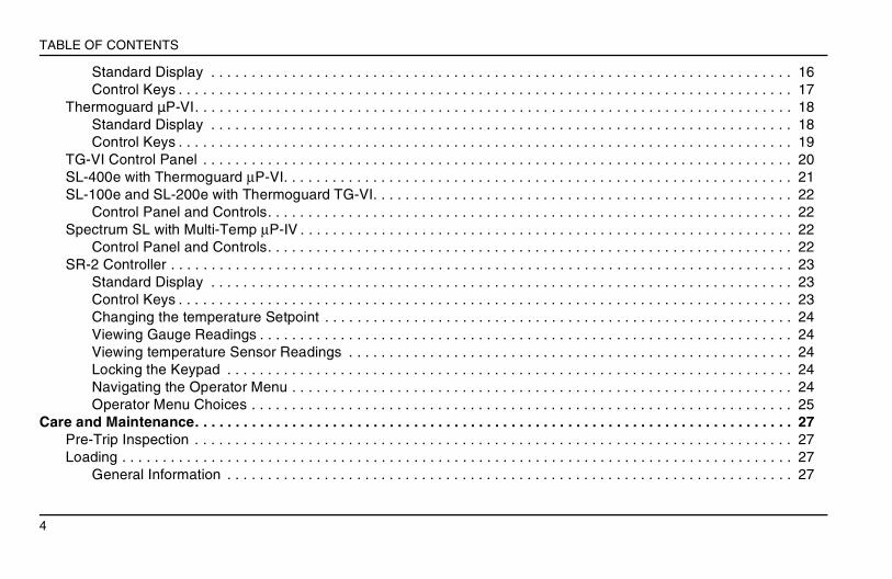
Standard Display . . . . . . . . . . . . . . . . . . . . . . . . . . . . . . . . . . . . . . . . . . . . . . . . . . . . . . . . . . . . . . . . . . . . . . . . 16Control Keys . . . . . . . . . . . . . . . . . . . . . . . . . . . . . . . . . . . . . . . . . . . . . . . . . . . . . . . . . . . . . . . . . . . . . . . . . . . . 17
Thermoguard µP-VI. . . . . . . . . . . . . . . . . . . . . . . . . . . . . . . . . . . . . . . . . . . . . . . . . . . . . . . . . . . . . . . . . . . . . . . . . . 18Standard Display . . . . . . . . . . . . . . . . . . . . . . . . . . . . . . . . . . . . . . . . . . . . . . . . . . . . . . . . . . . . . . . . . . . . . . . . 18Control Keys . . . . . . . . . . . . . . . . . . . . . . . . . . . . . . . . . . . . . . . . . . . . . . . . . . . . . . . . . . . . . . . . . . . . . . . . . . . . 19
TG-VI Control Panel . . . . . . . . . . . . . . . . . . . . . . . . . . . . . . . . . . . . . . . . . . . . . . . . . . . . . . . . . . . . . . . . . . . . . . . . . 20SL-400e with Thermoguard µP-VI. . . . . . . . . . . . . . . . . . . . . . . . . . . . . . . . . . . . . . . . . . . . . . . . . . . . . . . . . . . . . . . 21SL-100e and SL-200e with Thermoguard TG-VI. . . . . . . . . . . . . . . . . . . . . . . . . . . . . . . . . . . . . . . . . . . . . . . . . . . . 22
Control Panel and Controls. . . . . . . . . . . . . . . . . . . . . . . . . . . . . . . . . . . . . . . . . . . . . . . . . . . . . . . . . . . . . . . . . 22Spectrum SL with Multi-Temp µP-IV . . . . . . . . . . . . . . . . . . . . . . . . . . . . . . . . . . . . . . . . . . . . . . . . . . . . . . . . . . . . . 22
Control Panel and Controls. . . . . . . . . . . . . . . . . . . . . . . . . . . . . . . . . . . . . . . . . . . . . . . . . . . . . . . . . . . . . . . . . 22SR-2 Controller . . . . . . . . . . . . . . . . . . . . . . . . . . . . . . . . . . . . . . . . . . . . . . . . . . . . . . . . . . . . . . . . . . . . . . . . . . . . . 23
Standard Display . . . . . . . . . . . . . . . . . . . . . . . . . . . . . . . . . . . . . . . . . . . . . . . . . . . . . . . . . . . . . . . . . . . . . . . . 23Control Keys . . . . . . . . . . . . . . . . . . . . . . . . . . . . . . . . . . . . . . . . . . . . . . . . . . . . . . . . . . . . . . . . . . . . . . . . . . . . 23Changing the temperature Setpoint . . . . . . . . . . . . . . . . . . . . . . . . . . . . . . . . . . . . . . . . . . . . . . . . . . . . . . . . . . 24Viewing Gauge Readings . . . . . . . . . . . . . . . . . . . . . . . . . . . . . . . . . . . . . . . . . . . . . . . . . . . . . . . . . . . . . . . . . . 24Viewing temperature Sensor Readings . . . . . . . . . . . . . . . . . . . . . . . . . . . . . . . . . . . . . . . . . . . . . . . . . . . . . . . 24Locking the Keypad . . . . . . . . . . . . . . . . . . . . . . . . . . . . . . . . . . . . . . . . . . . . . . . . . . . . . . . . . . . . . . . . . . . . . . 24Navigating the Operator Menu . . . . . . . . . . . . . . . . . . . . . . . . . . . . . . . . . . . . . . . . . . . . . . . . . . . . . . . . . . . . . . 24Operator Menu Choices . . . . . . . . . . . . . . . . . . . . . . . . . . . . . . . . . . . . . . . . . . . . . . . . . . . . . . . . . . . . . . . . . . . 25
Care and Maintenance. . . . . . . . . . . . . . . . . . . . . . . . . . . . . . . . . . . . . . . . . . . . . . . . . . . . . . . . . . . . . . . . . . . . . . . . . . 27Pre-Trip Inspection . . . . . . . . . . . . . . . . . . . . . . . . . . . . . . . . . . . . . . . . . . . . . . . . . . . . . . . . . . . . . . . . . . . . . . . . . . 27Loading . . . . . . . . . . . . . . . . . . . . . . . . . . . . . . . . . . . . . . . . . . . . . . . . . . . . . . . . . . . . . . . . . . . . . . . . . . . . . . . . . . . 27
General Information . . . . . . . . . . . . . . . . . . . . . . . . . . . . . . . . . . . . . . . . . . . . . . . . . . . . . . . . . . . . . . . . . . . . . . 27
5
TABLE OF CONTENTS
Inspecting the Load . . . . . . . . . . . . . . . . . . . . . . . . . . . . . . . . . . . . . . . . . . . . . . . . . . . . . . . . . . . . . . . . . . . . . . .28Enroute Inspections . . . . . . . . . . . . . . . . . . . . . . . . . . . . . . . . . . . . . . . . . . . . . . . . . . . . . . . . . . . . . . . . . . . . . . .28
Maintenance Inspection Schedule . . . . . . . . . . . . . . . . . . . . . . . . . . . . . . . . . . . . . . . . . . . . . . . . . . . . . . . . . . . . . . .29Specifications . . . . . . . . . . . . . . . . . . . . . . . . . . . . . . . . . . . . . . . . . . . . . . . . . . . . . . . . . . . . . . . . . . . . . . . . . . . . . . . . .31
Engine TK 486V (SL-100e, SL-200e, SL-400e, Spectrum SL). . . . . . . . . . . . . . . . . . . . . . . . . . . . . . . . . . . . . . . . . .31Belt Tension (Using Tool No. 204-427) . . . . . . . . . . . . . . . . . . . . . . . . . . . . . . . . . . . . . . . . . . . . . . . . . . . . . . . . . . .32Electrical Control System . . . . . . . . . . . . . . . . . . . . . . . . . . . . . . . . . . . . . . . . . . . . . . . . . . . . . . . . . . . . . . . . . . . . . .33Electric Motor (Model 50) . . . . . . . . . . . . . . . . . . . . . . . . . . . . . . . . . . . . . . . . . . . . . . . . . . . . . . . . . . . . . . . . . . . . . .33Standby Power Requirements . . . . . . . . . . . . . . . . . . . . . . . . . . . . . . . . . . . . . . . . . . . . . . . . . . . . . . . . . . . . . . . . . .33
Safety Decals and Serial Numbers . . . . . . . . . . . . . . . . . . . . . . . . . . . . . . . . . . . . . . . . . . . . . . . . . . . . . . . . . . . . . . . .35Safety Decals and Locations . . . . . . . . . . . . . . . . . . . . . . . . . . . . . . . . . . . . . . . . . . . . . . . . . . . . . . . . . . . . . . . . . . .35Serial Number Decals and Locations . . . . . . . . . . . . . . . . . . . . . . . . . . . . . . . . . . . . . . . . . . . . . . . . . . . . . . . . . . . . .35Units with ELC (Extended Life Coolant) . . . . . . . . . . . . . . . . . . . . . . . . . . . . . . . . . . . . . . . . . . . . . . . . . . . . . . . . . . .36SL-400e Units with SR-2 Controller . . . . . . . . . . . . . . . . . . . . . . . . . . . . . . . . . . . . . . . . . . . . . . . . . . . . . . . . . . . . . .36
Warranty. . . . . . . . . . . . . . . . . . . . . . . . . . . . . . . . . . . . . . . . . . . . . . . . . . . . . . . . . . . . . . . . . . . . . . . . . . . . . . . . . . . . . .37Warranty Coverage: Diesel Truck and Trailer Products . . . . . . . . . . . . . . . . . . . . . . . . . . . . . . . . . . . . . . . . . . . . . . .37Warranty Summary: Diesel Truck and Trailer Products . . . . . . . . . . . . . . . . . . . . . . . . . . . . . . . . . . . . . . . . . . . . . . .37
Declarations of Conformity . . . . . . . . . . . . . . . . . . . . . . . . . . . . . . . . . . . . . . . . . . . . . . . . . . . . . . . . . . . . . . . . . . . . . .39Declaration of conformity with EC directive 2000/14/EC . . . . . . . . . . . . . . . . . . . . . . . . . . . . . . . . . . . . . . . . . . .40

6
TABLE OF CONTENTS
7
INTRODUCTION
INTRODUCTION
GENERAL INFORMATIONThe driver’s manual is published for informational purposes only and the information being furnished herein should not be considered as all-inclusive or meant to cover all contingencies. If further information is required, consult your Thermo King Service Directory for the location and phone number of the local dealer.All service requirements, major and minor, should be handled by a Thermo King dealer. Performing pre-trip checks on a regular basis minimizes operating problems. A closely followed maintenance program will also help keep your unit in top operating condition (see the “Maintenance Inspection Schedule” in this manual).
THERMO ASSISTANCEThermo Assistance is a multi-lingual communication tool designed to put you in direct contact with an authorized Service Dealer should you require one.
To use this system, you need the following information before you call:• Your Phone Number• Type of Thermo King Unit Model
• Thermostat Setting• Present Load Temperature• Probable Cause of Fault• Warranty Details of the Unit• Payment Details for the RepairRefer to the Thermo King Service Directory.Leave your name and contact number and a Thermo Assistance Operator will call you back. At this point you can give details of the service required and the repair will be organized.Please note that Thermo Assistance cannot guarantee payments and the service is designed for the exclusive use of refrigerated transporters with products manufactured by Thermo King Corporation.
+
DISCLAIMER
The manufacturer, Thermo King Corporation, assumes no responsibility for any act or action taken on the part of the owner or operator in the repair or operation of the products covered by this manual that are contrary to the manufacturer’s printed instructions. No warranties expressed or implied, including warranties arising from cause of dealing or usage or trade, are made regarding the information, recommendations, and description contained herein. The manufacturer is not responsible and will not be held liable in contract or in tort (including negligence) for any special, indirect or consequential damages, including injury or damage caused to vehicles, contents or persons, by reason of the installation of any Thermo King product, its mechanical failure or the failure of owner/operator to heed caution and safety decals strategically located on the product.
+45-79-42-42-22

8
INTRODUCTION
9
FIRST AID AND SAFETY
FIRST AID AND SAFETY
REFRIGERANTEYESImmediately flush eyes with large amounts of water and get prompt medical attention.SKINFlush area with large amounts of warm water. Do not apply heat. Wrap burns with dry, sterile, bulky dressing to protect from infection/injury and get medical attention.INHALATIONMove victim to a fresh air location and restore breathing if necessary. Stay with them until the arrival of emergency medical personnel.
REFRIGERANT OILEYESImmediately flush eyes with large amounts of water for at least 15 minutes while holding the eyelids open. Get prompt medical attention.SKINRemove any contaminated clothing. Wash thoroughly with soap and water. Get medical attention if irritation persists.INHALATIONMove victim to a fresh air location and restore breathing if necessary. Stay with them until arrival of emergency personnel.
INGESTIONDo not induce vomiting. Contact local poison control centre or physician immediately.
REFRIGERANT INFORMATIONAlways observe caution when working with refrigerants and in areas where they are being used.Fluorocarbon refrigerants evaporate rapidly, freezing anything that they come in contact with if accidentally released to the atmosphere from their liquid state.Refrigerants may produce toxic gases which, in the presence of an open flame or electrical short, can become severe respiratory irritants which can be fatal.Refrigerants displace air and can cause oxygen depletion which could result in death by suffocation. Observe caution at all times when working with or around refrigerant, or air conditioning systems which contain refrigerant, especially in enclosed or confined areas.
SAFETY PRECAUTIONSThermo King recommends all services be performed by a Thermo King dealer. However, there are several general safety practices which you should be aware of:1. Always wear safety glasses when working
with or around the refrigeration system or battery.Refrigerant or battery acid can cause permanent damage if it comes in contact with your eyes.
2. Never operate the unit with the compressor discharge valve closed.
3. Always keep your hands and loose clothing clear of fans and belts when unit is running or when opening or closing compressor service valves.
4. Always use extreme caution if you ever have occasion to drill holes in your unit. This could weaken structural components. Drilling into electrical wiring or refrigerant lines could cause a fire.
5. All service work on evaporator or condenser coils be completed by a certified Thermo King technician. If you ever do have occasion to be working around the coils, use extreme caution as exposed coil fins could cause painful lacerations.
RECOVER REFRIGERANT
At Thermo King we recognize the need to preserve the environment and limit the potential harm to the ozone layer that can result from allowing refrigerant to escape into the atmosphere. We strictly adhere to a policy that promotes the recovery and limits the loss of refrigerant into the atmosphere.
10
FIRST AID AND SAFETY
AUTO START/STOP OPERATIONThis unit may start up at any time without prior warning.
CYCLE-SENTRYIf your unit is equipped for CYCLE-SENTRY operation, the unit may start automatically at any time when the unit is turned on and the CYCLE-SENTRY is selected.
ELECTRIC STANDBYOn Model 50 units, the unit may start automatically at any time when the unit is switched on, connected to live electric power and/or the Electric operation is selected.Be sure to switch the unit off before opening the doors or inspecting any part of the unit.
ELECTRICAL HAZARDUnits with electric operation or electric standby present a potential electrical hazard. Always disconnect the high voltage power cable before working on the unit.
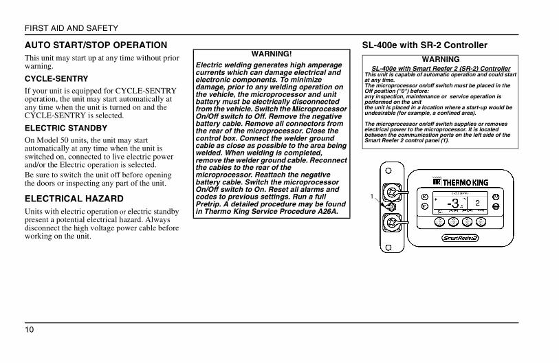
SL-400e with SR-2 ControllerWARNING!
Electric welding generates high amperage currents which can damage electrical and electronic components. To minimize damage, prior to any welding operation on the vehicle, the microprocessor and unit battery must be electrically disconnected from the vehicle. Switch the Microprocessor On/Off switch to Off. Remove the negative battery cable. Remove all connectors from the rear of the microprocessor. Close the control box. Connect the welder ground cable as close as possible to the area being welded. When welding is completed, remove the welder ground cable. Reconnect the cables to the rear of the microprocessor. Reattach the negative battery cable. Switch the microprocessor On/Off switch to On. Reset all alarms and codes to previous settings. Run a full Pretrip. A detailed procedure may be found in Thermo King Service Procedure A26A.
WARNINGSL-400e with Smart Reefer 2 (SR-2) Controller
This unit is capable of automatic operation and could start at any time. The microprocessor on/off switch must be placed in the Off position ("0") before: any inspection, maintenance or service operation is performed on the unitthe unit is placed in a location where a start-up would be undesirable (for example, a confined area).
The microprocessor on/off switch supplies or removes electrical power to the microprocessor. It is located between the communication ports on the left side of the Smart Reefer 2 control panel (1).
1
11
UNIT DESCRIPTION
UNIT DESCRIPTION
GENERAL INFORMATIONThe Thermo King SL models are one piece, self-contained, diesel powered cooling/ heating units operating under the control of a programmable microprocessor controller. The units mount on the front of the trailer with the evaporator extending through an opening in the front wall.There are several models:• SL-100e, SL-200e and SL-400e Model 30:
Cooling and heating on diesel engine operation.
• SL-100e, SL-200e and SL-400e Model 50: Cooling and heating on diesel engine or electric motor operation.
• Spectrum SL 30: Multiple trailer compartment cooling and heating on diesel engine operation
• Spectrum SL 50: Multiple trailer compartment cooling and heating on diesel or electric motor operation.
Power is provided by a 4-cylinder, water-cooled, direct injection diesel engine. The engine is coupled directly to the compressor. Belts convey power to the unit fans, alternator and water pump.
During diesel engine operation, the unit will operate in one of the following modes depending on the air temperature in the trailer, as sensed by the microprocessor controller:Continuous Run Operation• High Speed Cool• Low Speed Cool• Low Speed Modulated Cool (if equipped
with Modulation)• Low Speed Modulated Heat (if equipped
with Modulation)• Low Speed Heat• High Speed Heat• DefrostCYCLE-SENTRY Operation (Optional)• High Speed Cool• Low Speed Cool• Null (Engine Off)• Low Speed Heat• High Speed Heat• DefrostGenerally, the unit will operate in low speed, switching back and forth from cooling to heating as necessary.On very hot days, with the setpoint at a low temperature, the unit may cycle between high speed cool and low speed cool without switching into a heating cycle.
Likewise, on very cold days, the unit may cycle between high speed heat and low speed heat. The unit may switch into cooling for short periods of time.The electric motor on Model 50 units is an 11.7 hp, 1450 RPM induction motor operating on 220/380 volt, 3 phase, 50 hertz power. The electric motor powers the compressor through a belt and clutch system.During Standby electric operation, the Model 50 units operate in one of the following modes to maintain the trailer temperature:• Cool• Motor Off• Heat• Defrost
THERMO KING COMPRESSORSSL-400e and Spectrum SL units feature the Thermo King X430, 4-cylinder compressor with 492 cc displacement.The SL-100e and SL-200e feature the X426 4-cylinder compressor with 423 cc displacement.
12
UNIT DESCRIPTION
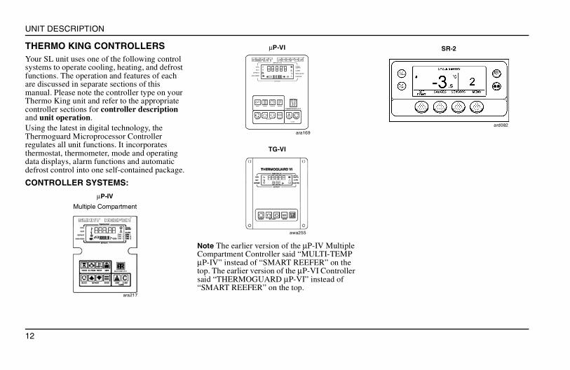
THERMO KING CONTROLLERSYour SL unit uses one of the following control systems to operate cooling, heating, and defrost functions. The operation and features of each are discussed in separate sections of this manual. Please note the controller type on your Thermo King unit and refer to the appropriate controller sections for controller description and unit operation.Using the latest in digital technology, the Thermoguard Microprocessor Controller regulates all unit functions. It incorporates thermostat, thermometer, mode and operating data displays, alarm functions and automatic defrost control into one self-contained package.
CONTROLLER SYSTEMS:
Note The earlier version of the µP-IV Multiple Compartment Controller said “MULTI-TEMP µP-IV” instead of “SMART REEFER” on the top. The earlier version of the µP-VI Controller said “THERMOGUARD µP-VI” instead of “SMART REEFER” on the top.
µP-IV
Multiple Compartment
ara217
SELECT SETPOINT ENTER
ALARM
HOURSMODE GAUGES PRETRIP
TEMPERATURE
SETPOINT
COOL
HEAT
DEFROST
HIGH SPEED
CYCLE
SENTRY
ALARM
MODULATION
IN-RANGE
!
CODE CLEAR
THERMOGUARD uP VI
µP-VI
ara169
TG-VI
awa255
SR-2
ard082
13
UNIT DESCRIPTION
CYCLE-SENTRY START/STOP CONTROLSThe CYCLE-SENTRY system automatically starts up the unit when heating or cooling is required and shuts it off when the cargo box temperature reaches the controller setpoint.The CYCLE-SENTRY system also maintains engine temperature by restarting the unit if the engine block temperature drops below -1°C. It runs until the controller demand is satisfied and the engine block temperature reaches 32°C.CYCLE-SENTRY is designed for use only with products which do not require tight temperature control or continuous airflow, such as all deep frozen products and non-perishable non-frozen products.The start/stop nature of CYCLE-SENTRY does not satisfy the temperature control or airflow requirements for perishable or temperature sensitive products. Thermo King therefore does NOT recommend the use of CYCLE-SENTRY control for these products.
DEFROSTAs the unit is operated to cool the trailer, frost will gradually build up on the evaporator coils. Periodically this frost must be melted to prevent loss of cooling and airflow.Defrost is accomplished by passing hot refrigerant gas through the evaporator coils, thus melting the frost (or ice). Melted frost drains out of the unit onto the ground through the drain tubes. The defrost damper closes during defrost to prevent warm air from entering the cargo area.
MODULATIONSystems equipped with modulation can provide precise temperature control of fresh products. This can reduce product dehydration, increase product shelf life and protect fresh products from freeze damage.As the return air temperature falls toward setpoint, the unit closes a modulation valve to throttle suction gas returning to the compressor and reduce unit cooling capacity. If additional reduction in cooling capacity is needed, the unit will open a hot gas injection solenoid, injecting hot gas directly into the evaporator coil.
WARNING!Set the unit On/Off switch to OFF before opening doors or inspecting any part of the unit. With the Continuous/Cycle switch in the CYCLE position, and the unit On/Off switch in the ON position, the unit may start at any time without warning.

14
UNIT DESCRIPTION
15
CONTROLLER DESCRIPTION
CONTROLLER DESCRIPTION
THERMOGUARD µP-IV
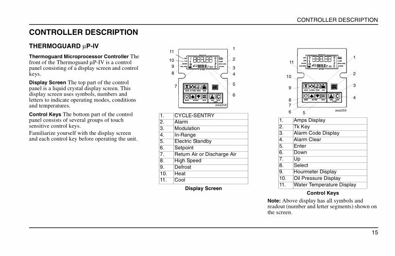
Thermoguard Microprocessor Controller The front of the Thermoguard µP-IV is a control panel consisting of a display screen and control keys.
Display Screen The top part of the control panel is a liquid crystal display screen. This display screen uses symbols, numbers and letters to indicate operating modes, conditions and temperatures.
Control Keys The bottom part of the control panel consists of several groups of touch sensitive control keys.Familiarize yourself with the display screen and each control key before operating the unit.
Note: Above display has all symbols and readout (number and letter segments) shown on the screen.
1. CYCLE-SENTRY2. Alarm3. Modulation4. In-Range5. Electric Standby6. Setpoint7. Return Air or Discharge Air8. High Speed9. Defrost10. Heat11. Cool
Display Screen
11
109
8
7
1
2
34
5
6
awa258
1. Amps Display2. Tk Key3. Alarm Code Display4. Alarm Clear5. Enter6. Down7. Up8. Select9. Hourmeter Display10. Oil Pressure Display11. Water Temperature Display
Control Keys
1
2
3
4
11
10
9
87
6 5awa259
16
CONTROLLER DESCRIPTION
DISPLAY SYMBOLS
STANDARD DISPLAYThe Thermoguard µP-IV controller normally shows the Standard Display of return air temperature and setpoint. Temperatures will be displayed as follows:
Temperature Displays
Upper Readout: Temperatures displayed on the upper readout are shown by:• a degree symbol and letter C representing
Celsius degrees and letter F representing Fahrenheit degrees.
• decimal point and number representing 1/10 degrees.
• numbers representing whole degrees (2 or 3 digits).
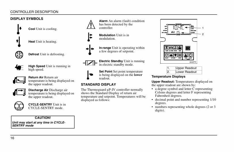
Cool Unit is cooling.
Heat Unit is heating.
Defrost Unit is defrosting.
High Speed Unit is running in high speed.
Return Air Return air temperature is being displayed on the upper readout.
Discharge Air Discharge air temperature is being displayed on the upper readout.
CYCLE-SENTRY Unit is in CYCLE-SENTRY mode.
CAUTION!Unit may start at any time in CYCLE- SENTRY mode
Alarm An alarm (fault) condition has been detected by the controller.
Modulation Unit is in modulation.
In-range Unit is operating within a few degrees of setpoint.
Electric Standby Unit is running in electric standby mode.
Set Point Set point temperature is being displayed on the lower readout.
1. Upper Readout2. Lower Readout
1
2
awa272
17
CONTROLLER DESCRIPTION
Temperature types are identified by one of two temperature symbols:• Return air temperature is indicated by arrow
pointing left.• Discharge air temperature (DIS.A) is
indicated by arrow pointing to the right.
Lower Readout Unit setpoint temperature is normally displayed on the lower readout. Setpoint is the temperature at which the unit will be controlling.Setpoint is indicated by numbers representing whole degrees (1 or 2 digits) A setpoint symbol will be on the screen to the right of the lower readout, whenever the setpoint is displayed.Thermoguard µP-IV standard setpoint range is -29 to 27 C (-20 to 80 F). The programmable range is -32 to 32 C (-25 to 90 F). The controller can be programmed to show setpoint to the nearest tenth of a degree (.1). In that case the display will show:• a decimal point and number representing
tenths (.1) degrees.• numbers representing whole degrees (1 or 2
digits.
CONTROL KEYS
HOURMETER Key Selects the hour meter displays.
OIL PRESSURE Key Selects the engine oil pressure display.
AMPS Key Selects the amps display indicating amps to or from the battery. A minus (–) sign indicates discharge.
WATER TEMPERATURE Key Selects the engine water temperature display.
TK LOGO Key Used with other keys to select special displays or start operational tests.
ALARM Key This key is used to select the alarm code display.
ALARM CLEAR Key This key is used to clear alarms when they are on the display.
SELECT Key Cycling arrows) Selects the following displays:
• [dEF] Defrost Prompt Screen.• [CYCLS] Cycle Sentry Prompt
Screen.• DIS.A Discharge Air Temp.• TPDF Temperature Differential
between Return Air and Discharge Air.
• COIL Evaporator Coil Temp.• AMB.T Ambient Air Temperature.• SPR.1 &
SPR.2Spare Sensor #1 and #2 temperatures (not normally used).
• BATV Battery Voltage.• RPM Engine Revolutions per
Minute.• DEFI Defrost Interval In-Range
(in hours).• DEFN Defrost Interval Not In
Range (in hours).• DDUR Defrost Duration
(maximum in minutes).• MVST Modulated Valve Start (yes
or no) (Only with modulation option).
18
CONTROLLER DESCRIPTION
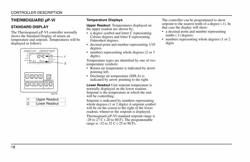
THERMOGUARD µP-VI
STANDARD DISPLAYThe Thermoguard µP-VI controller normally shows the Standard Display of return air temperature and setpoint. Temperatures will be displayed as follows:
Temperature Displays
Upper Readout: Temperatures displayed on the upper readout are shown by:• a degree symbol and letter C representing
Celsius degrees and letter F representing Fahrenheit degrees.
• decimal point and number representing 1/10 degrees.
• numbers representing whole degrees (2 or 3 digits).
Temperature types are identified by one of two temperature symbols:• Return air temperature is indicated by arrow
pointing left.• Discharge air temperature (DIS.A) is
indicated by arrow pointing to the right.
Lower Readout Unit setpoint temperature is normally displayed on the lower readout. Setpoint is the temperature at which the unit will be controlling.Setpoint is indicated by numbers representing whole degrees (1 or 2 digits) A setpoint symbol will be on the screen to the right of the lower readout, whenever the setpoint is displayed.Thermoguard µP-VI standard setpoint range is -29 to 27 C (-20 to 80 F). The programmable range is -32 to 32 C (-25 to 90 F).
The controller can be programmed to show setpoint to the nearest tenth of a degree (.1). In that case the display will show:• a decimal point and number representing
tenths (.1) degrees.• numbers representing whole degrees (1 or 2
digits.
1. Upper Readout2. Lower Readout
SELECT SETPOINT ENTER
ALARM
HOURSMODE GAUGES PRETRIP
TEMPERATURE
SETPOINT
COOL
HEAT
DEFROST
HIGH SPEED
CYCLESENTRY
ALARM
MODULATION
IN-RANGE
CODE CLEAR
THERMOGUARD uP VI
1
2
ara170
19
CONTROLLER DESCRIPTION
CONTROL KEYS
MODE Key Selects the mode displays.
HOURMETER Key Selects the hourmeter displays.
PRE-TRIP Key Selects Pre-trip operation.
GAUGES Key Selects the following displays:
• [WATT] Engine Water Temp.• [OILP] Oil Pressure.• [AMPS] Amps.• [BATV] Oil Pressure.• [RPM] Engine RPM.• [SUC.P] Suction Pressure.• [DIS.P] Discharge Pressure.• [ETV.P] ETV Valve Position.
ara
173
TK LOGO Key Used with other keys to select special displays or start operational tests.
Alarm Key This key is used to SELECT the alarm code display.
ALARM CLEAR Key This key is used to clear alarms when they are on the display.
SELECT Key Cycling arrows) Selects the following displays:
• DIS.A Discharge Air Temp.• TPDF Temperature Differential
between Return Air and Discharge Air.
• COIL Evaporator Coil Temp.• AMB.T Ambient Air Temperature.• SPR.1 &
SPR.2Spare Sensor #1 and #2 temperatures (not normally used).
20
CONTROLLER DESCRIPTION
TG-VI CONTROL PANEL
The TG-VI has the following features:• System Controller.• Alert System.• Cycle Sentry (optional).• Return Air Temperature Sensor.• Discharge Air Temperature Sensor.• Coil Temperature Sensor.• Total Hours Hourmeter.• Engine Hours Hourmeter.• Electric Hours Hourmeter.• Oil Pressure Display.• Engine Coolant Temperature Display.• Engine Tachometer Display.• Battery Voltage Display.
Engine starts are fully automatic in both Continuous and CYCLE-SENTRY mode. Initiating a manual defrost cycle and selecting Continuous or CYCLE-SENTRY operation (on units equipped with CYCLE-SENTRY) is accomplished using the TG-VI SELECT and ENTER keys. See unit operating instructions.The TG-VI front panel contains an LCD display and a keypad containing five touch sensitive keys.
1. Display. Normally shows Standard Display of return air temperature and setpoint. When unit is turned on, display will indicate current operating mode by an icon (symbol) that appears next to description on either side of the display.Display is also used to show Prompt screens (such as Defrost) and Display screens (such as engine oil pressure). Display will be blank when unit On/Off switch is off.
2. SELECT Key. SELECT Key allows operator to select Prompt screens and Display screens. Prompt Screens are used to select CYCLE-SENTRY or Continuous operation (of a CYCLE-SENTRY unit), and initiate manual defrost cycle. SELECT Key is also used to select Display screens to display other operating data such as engine speed or oil pressure.
3. UP and DOWN ARROW Keys. Keys increase or decrease setpoint and chose other selections from some of the Prompt Screens.
4. Mode Description. Descriptions show possible operating modes and indicate alarms.
5. Icons. Will appear next to the appropriate description when unit is operating in that mode.
6. ENTER Key. Used to enter a new command such as manual defrost, new setpoint, etc.
7. THERMO KING LOGO Key. Is used to initiate Unit Self Check, to view software revision number, enter Service Test mode and Relay Board Test.
awa281
CAUTION!This unit may start automatically any time the On/Off switch is turned “ON.”
21
CONTROLLER DESCRIPTION
SL-400e WITH THERMOGUARD µP-VI1. On/Off Switch This switch is used to turn the unit on and off.• In the ON position, the unit will operate in
the selected mode.• In the OFF position the electrical circuits are
disconnected from the battery. The fuel supply is shut off and the unit will not run.
NOTE: Sleep mode is used to automatically start and run the unit as required to maintain engine temperature above 2 C (35 F) and the unit battery in a charged condition. To enter Sleep mode press the MODE key repeatedly to display [SLEEP]. Press the ENTER key to load the Sleep mode. [YES] or [nO] and [STR.T] will appear. • To enter Sleep mode with an exit time press
an ARROW key (if necessary) to display [YES] and[STR.T], then press the ENTER key to load it. [SdAY] and a day will appear. Use the ARROW keys to select the start day and press the ENTER key to load it. This is the day the unit is to exit the Sleep mode and return to normal CYCLE-SENTRY operation. This start day can be no more than a week in the future. Press the SELECT key. A number and [SHR] will appear. Use the ARROW keys to select the start hour and press the ENTER key to load it. Press the SELECT key. A number and [SMN] will appear. Use the ARROW keys to select the
start minute and press the ENTER key to load it. Press the SELECT key. [SLEEP] and [MODE] will appear.
• To enter Sleep Mode without an exit time press an Arrow Key (if necessary) to display [nO] and [STR.T], then press the Enter Key to load the Sleep Mode.[SLEEP] and [MODE] will appear.
Place the On/Off switch in the Off position exit the Sleep Mode.
2. Electric/Diesel Switch. (Model 50 only)• In ELECTRIC position, unit is powered by
standby electric motor.• In DIESEL position, unit is powered by
diesel engine.
3. Electric Motor Reset. (Model 50 only). Push button switch protects the electric motor from overload.
DIESELDIESEL
ELECTRICELECTRICONON
OFFOFF
SELECT SETPOINT ENTER
ALARM
HOURSMODE GAUGES PRETRIP
TEMPERATURE
SETPOINT
COOL
HEAT
DEFROST
HIGH SPEED
CYCLE
SENTRY
ALARM
MODULATION
IN-RANGE
!
CODE CLEAR
THERMOGUARD uP VI
ara174
21
3
CAUTION!The unit does not control the box temperature to setpoint during Sleep Mode operation. If the load must be temperature controlled, DO NOT USE SLEEP MODE.
22
CONTROLLER DESCRIPTION
SL-100e AND SL-200e WITH THERMOGUARD TG-VI
CONTROL PANEL AND CONTROLS
All unit functions and operation are controlled by the Thermoguard VI Microprocessor controller. The On/Off switch serves only to provide system power. Once the switch is “ON,” unit operation is automatic (per programmed settings).
SPECTRUM SL WITH MULTI-TEMP µP-IV
CONTROL PANEL AND CONTROLS
1. Microprocessor On/Off Switch. This switch supplies power to the microprocessor, which is required for the unit to function.
• In the ON position, battery power is applied to the control circuits.
• In the OFF position the microprocessor circuits are disconnected from the battery. The fuel supply is shut off and the unit will not run.
2. Zone 1 On/Off Switch (main on/off unit) This switch supplies power to components which control temperatures in trailer compartment Zone 1 and to engine controls.
3. Electric/Diesel Switch. (Model 50 only) • In ELECTRIC position, unit is powered by
standby electric motor.• In DIESEL position, unit is powered by
diesel engine.
4. Zone 2 On/Off Switch. This switch supplies power to components which control temperatures in trailer compartment Zone 2.
5. Zone 3 On/Off Switch. This switch supplies power to components which control temperatures in trailer compartment Zone 3.Multi-Temp displays and control keys are similar to Thermoguard features shown previously. “Multi-Temp” refers to multiple cargo compartment temperature control. The Multi-Temp controller display shows information for each compartment (“Zone”). Use the Zone switches and the SELECT key to select each zone when programming setpoint temperatures.
1. Start/Preheat2. On/Off Switch
1
2
awa284
ara218
31 4 52
23
CONTROLLER DESCRIPTION
SR-2 CONTROLLER
The microprocessor on/off switch must be placed in the Off position ("0") before:• Any inspection, maintenance or service
operation is performed on the unit.• The unit is placed in a location where a
start-up would be undesirable (for example,a confined area).
The microprocessor on/off switch supplies or removes electrical power to the microprocessor. It is located between the communication ports on the left side of the SR-2 control panel.
STANDARD DISPLAYThe Standard Display shows the box temperature and setpoint. The top of the display shows the unit is operating in either CYCLE-SENTRY or Continuous Run mode.The Standard Display defaults to the Temperature Watch Display after about 2-1/2 minutes of non-use. The Temperature Watch Display shows the same box temperature and setpoint but in larger fonts.
CONTROL KEYS
WARNING!This unit is capable of automatic operation and could start at any time.
1. On/Off Main Switch2. Data Logger Port3. Printer Port4. On Key (Dedicated Key5. Off Key (Dedicated Key)6. Display7. Defrost Key (Dedicated Key)8. Mode Key (Dedicated Key)9. Soft Keys
1
2
4
7
8
9
3
5
6
On Key Turns the unit on.(hold 1 second)
Off Key Turns the unit off.
Defrost Key Initiates a Manual Defrost
Mode Key Switches the unit between the CYCLE-SENTRY and Continuous Run modes.
Soft Keys The four soft keys are multi-purpose keys. Their function changes depending on the operation being performed. If a soft key is active, it’s function will be shown in the display directly above the key.
24
CONTROLLER DESCRIPTION
CHANGING THE TEMPERATURE SETPOINTTo change the setpoint complete the following steps:1. Press the Setpoint soft key on the Standard
Display. The “Current Setpoint” Screen will appear.
2. Press the + or - soft keys to change the setpoint reading.
3. Press the Yes or No soft key accordingly. – If the No key is pressed the setpoint
change made with the “+” or “-” soft keys will not be accepted, the setpoint will not be changed and the display will return to the Standard Display.
– If the Yes soft key was pressed, the setpoint change made with the “+” or “-” soft keys will be accepted.
The “Programming New Setpoint” Screen will appear.The “New Setpoint Is XX” Screen briefly appears.The Standard Display appears with setpoint changed to the new setpoint.
VIEWING GAUGE READINGSUse the following steps to view miscellaneous gauge readings:1. Press the Gauges soft key from the Standard
Display.2. Press Back or Next soft keys to scroll
through the gauge screens. If no keys are pressed within 30 seconds, the screen will return to the standard display.
3. Press the Lock soft key to display any Gauge Screen for an indefinite period. Press the key again to unlock the screen.
4. Press the Exit soft key to return to the Standard Display.
VIEWING TEMPERATURE SENSOR READINGSUse the following steps to view miscellaneous sensor readings:1. Press the Sensor soft key from the Standard
Display.2. Press the Back or Next soft keys to scroll
through the sensor screens. If no keys are pressed within 30 seconds, the screen will return to the Standard Display.
3. Press the Lock soft key to display any sensor screen for an indefinite period. Press the key again to unlock the screen.
4. Press the Exit soft key to return to the Standard Display.
LOCKING THE KEYPADUse the following steps to lock the keypad:1. Press the Menu soft key from the Standard
Display.2. Press Next and Back soft keys to scroll to the
Mode menu.3. Press the Keypad Lockout soft key.4. Confirm the keypad lockout by pressing
either the Yes or No soft key.5. Pressing any key for 10 seconds will unlock
the keypad.
NAVIGATING THE OPERATOR MENUThe Operator Menu contains nine individual menu areas that allow the operator to view information and modify unit operation. Use the following steps to access these menu areas:1. Press the Menu soft key from the Standard
Display.2. Press Next and Back soft keys to scroll up or
down through the nine main menu areas.3. Press the Select soft key to access a specific
menu area when shown on the display screen.
4. Press the Exit soft key to return to the Standard Display.
25
CONTROLLER DESCRIPTION
OPERATOR MENU CHOICES
Language Menu Selects the controller language.
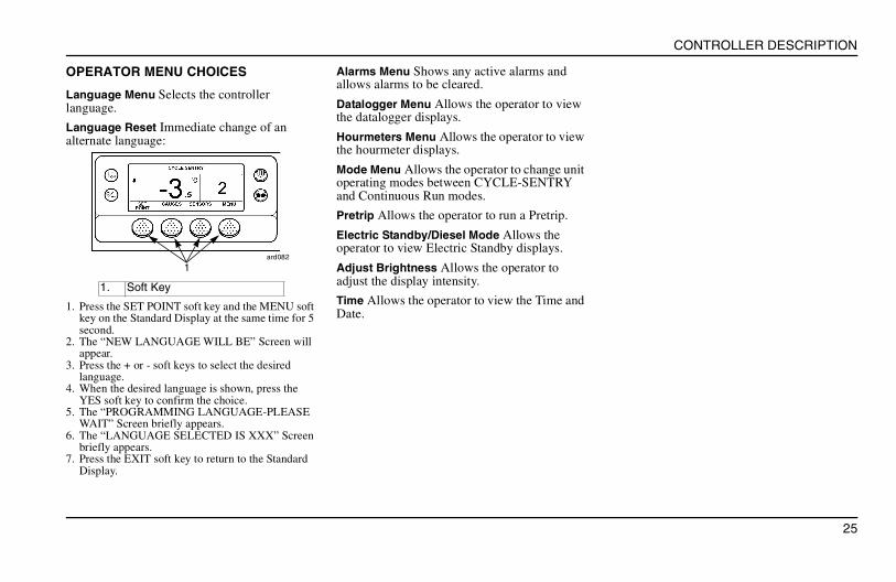
Language Reset Immediate change of an alternate language:
1. Press the SET POINT soft key and the MENU soft key on the Standard Display at the same time for 5 second.
2. The “NEW LANGUAGE WILL BE” Screen will appear.
3. Press the + or - soft keys to select the desired language.
4. When the desired language is shown, press the YES soft key to confirm the choice.
5. The “PROGRAMMING LANGUAGE-PLEASE WAIT” Screen briefly appears.
6. The “LANGUAGE SELECTED IS XXX” Screen briefly appears.
7. Press the EXIT soft key to return to the Standard Display.
Alarms Menu Shows any active alarms and allows alarms to be cleared.
Datalogger Menu Allows the operator to view the datalogger displays.
Hourmeters Menu Allows the operator to view the hourmeter displays.
Mode Menu Allows the operator to change unit operating modes between CYCLE-SENTRY and Continuous Run modes.
Pretrip Allows the operator to run a Pretrip.
Electric Standby/Diesel Mode Allows the operator to view Electric Standby displays.
Adjust Brightness Allows the operator to adjust the display intensity.
Time Allows the operator to view the Time and Date.
1. Soft Key
ard082
1
26
CONTROLLER DESCRIPTION
27
CARE AND MAINTENANCE
CARE AND MAINTENANCE
PRE-TRIP INSPECTIONPre-trip inspections are essential to minimize operating problems and breakdowns, and must be performed before every trip involving refrigerated cargo.1. Diesel FuelMust guarantee engine operation to the next check point.2. Engine OilShould be at the FULL mark. Never overfill.3. CoolantThe indicator should be in the FULL (white) range. If the coolant level is in the ADD (red) range, add coolant to the expansion tank. Coolant should be a 50/50 mixture of ethylene glycol and water to provide protection to -34°C.4. BatteryThe terminals must be tight and free of all corrosion. Electrolyte should be at full mark.5. BeltsThe belts must be in good condition and adjusted to the proper tension. Allow 13 mm deflection at the centre of the span between pulleys.
6. ElectricalEnsure all electrical connections are securely fastened. Wires and terminals should be free of corrosion, cracks or moisture.7. StructuralVisually inspect the unit for leaks, loose or broken parts and other damage.8. GasketThe unit mounting gasket should be tightly compressed and in good condition.9. CoilsEnsure condenser and evaporator coils are clean and free of debris.10. Cargo BoxInspect the interior and exterior of the trailer for damage. Any damage to the walls or insulation must be repaired.11. DamperThe damper in the evaporator air outlet must move freely with no sticking or binding.12. Defrost DrainsCheck the defrost drain hoses and fittings to ensure they are open.13. DoorsEnsure doors and weather seals are in good condition, doors latch securely and weather seals fit tightly.
LOADING
GENERAL INFORMATION1. Inspect the trailer for proper insulation.2. Ensure all door seals are tight seal with no air
leakage.3. Inspect the trailer inside and out for damaged
or loose doors or skin.4. On the inside, look for damaged walls, air
ducts, floor channels or “T” flooring, clogged defrost drain tubes and clogged or damaged floor channels which could block the air return, creating “Hot Spots” in the load.
5. Pre-cool the trailer as required.6. Ensure loads are at proper carrying
temperature when you pick them up. Note any variance.
7. Supervise loading of the product to assure sufficient air space around and through the load so as not to restrict air flow.
CAUTION!Do not remove the expansion tank cap while the coolant is hot.
28
CARE AND MAINTENANCE
INSPECTING THE LOADAlways inspect load prior to departure.1. Ensure unit is off before opening the trailer
doors. Otherwise refrigerated air is expelled hot air drawn in. The unit may be run with the doors open if the trailer is properly backed into a refrigerated warehouse.
2. Perform final external and internal load temperature checks. Note any irregularities on the manifest.
3. Ensure cargo is not blocking the evaporator inlets and outlets and that ample circulation space has been provided around the load.
4. Ensure trailer doors are securely locked.5. Ensure controller setpoint is at the desired
temperature.6. If the unit was stopped, restart using the
starting procedures outlined in this manual.7. Repeat the After Start Inspection.8. Defrost the unit one half-hour after loading
by selecting the Manual Defrost. The Defrost cycle terminates automatically.
INSPECTIONS DURING OPERATION1. Carry out an inspection every four hours
while a loaded trailer is either parked or in transit.
2. Note controller setpoint to ensure setting is unaltered since picking up the load.
3. Note the return air temperature, it should be +/- 4°C of the controller setpoint. If the temperature reading is not +/- 4°C of the controller setpoint, keep the unit running for 15 minutes and re-check the temperature. Wait 15 minutes more and if the temperature is still out of range, contact a Thermo King dealer for service.
4. We recommend you record the return air temperature reading each time you check the unit. This is important information if you need service later on.
Notes: If cargo temperature is too high it could indicate:• Evaporator is plugged with frost in which
case standard defrosting procedure is needed or there is improper air circulation within the cargo area.Inspect the unit to determine if the evaporator fan is working and circulating the usual amount of air. Poor circulation could be caused by:– Fan belt slipping or damaged. (Have the
fan belt checked by a qualified mechanic.)– Defrost damper damaged and stuck in
closed position.– Improper loading of product in trailer or
load shifting in transit so that there are restricted air passages around and through the load.
– Unit may have a low refrigerant charge. If you cannot see a liquid level in receiver tank sight glass with the unit running in COOL, it is an indication that the charge may be low.
It is advisable that any of the above mentioned problems found during your enroute inspection be referred to the nearest authorized Thermo King dealer as quickly as possible. Check your service directory for phone number and location.
29
CARE AND MAINTENANCE
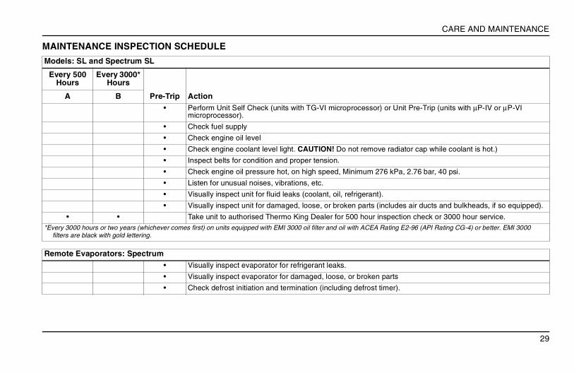
MAINTENANCE INSPECTION SCHEDULE
Models: SL and Spectrum SL
Every 500 Hours
Every 3000* Hours
Pre-Trip ActionA B• Perform Unit Self Check (units with TG-VI microprocessor) or Unit Pre-Trip (units with µP-IV or µP-VI
microprocessor).
• Check fuel supply
• Check engine oil level
• Check engine coolant level light. CAUTION! Do not remove radiator cap while coolant is hot.)
• Inspect belts for condition and proper tension.
• Check engine oil pressure hot, on high speed, Minimum 276 kPa, 2.76 bar, 40 psi.
• Listen for unusual noises, vibrations, etc.
• Visually inspect unit for fluid leaks (coolant, oil, refrigerant).
• Visually inspect unit for damaged, loose, or broken parts (includes air ducts and bulkheads, if so equipped).
• • Take unit to authorised Thermo King Dealer for 500 hour inspection check or 3000 hour service.*Every 3000 hours or two years (whichever comes first) on units equipped with EMI 3000 oil filter and oil with ACEA Rating E2-96 (API Rating CG-4) or better. EMI 3000
filters are black with gold lettering.
Remote Evaporators: Spectrum• Visually inspect evaporator for refrigerant leaks.
• Visually inspect evaporator for damaged, loose, or broken parts
• Check defrost initiation and termination (including defrost timer).

30
CARE AND MAINTENANCE
31
SPECIFICATIONS
SPECIFICATIONS
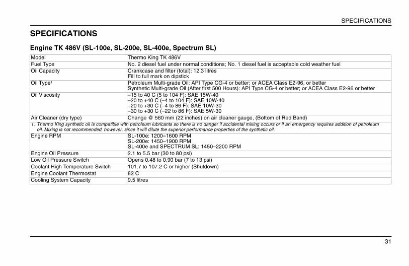
Engine TK 486V (SL-100e, SL-200e, SL-400e, Spectrum SL)Model Thermo King TK 486VFuel Type No. 2 diesel fuel under normal conditions; No. 1 diesel fuel is acceptable cold weather fuelOil Capacity Crankcase and filter (total): 12.3 litres
Fill to full mark on dipstickOil Type1 Petroleum Multi-grade Oil: API Type CG-4 or better; or ACEA Class E2-96, or better
Synthetic Multi-grade Oil (After first 500 Hours): API Type CG-4 or better; or ACEA Class E2-96 or better Oil Viscosity –15 to 40 C (5 to 104 F): SAE 15W-40
–20 to +40 C (–4 to 104 F): SAE 10W-40–20 to +30 C (–4 to 86 F): SAE 10W-30–30 to +30 C (–22 to 86 F): SAE 5W-30
Air Cleaner (dry type) Change @ 560 mm (22 inches) on air cleaner gauge, (Bottom of Red Band)1. Thermo King synthetic oil is compatible with petroleum lubricants so there is no danger if accidental mixing occurs or if an emergency requires addition of petroleum
oil. Mixing is not recommended, however, since it will dilute the superior performance properties of the synthetic oil. Engine RPM SL-100e: 1200–1600 RPM
SL-200e: 1450–1900 RPMSL-400e and SPECTRUM SL: 1450–2200 RPM
Engine Oil Pressure 2.1 to 5.5 bar (30 to 80 psi)Low Oil Pressure Switch Opens 0.48 to 0.90 bar (7 to 13 psi)Coolant High Temperature Switch 101.7 to 107.2 C or higher (Shutdown)Engine Coolant Thermostat 82 CCooling System Capacity 9.5 litres
32
SPECIFICATIONS
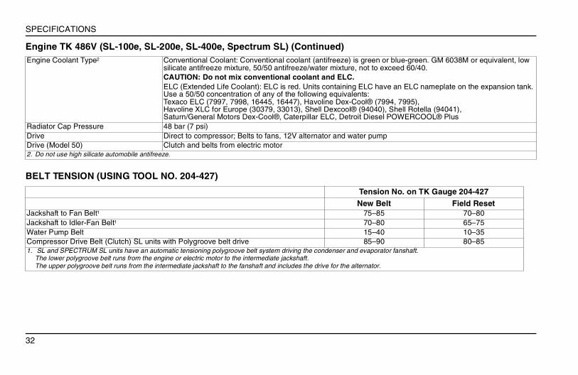
Engine Coolant Type2 Conventional Coolant: Conventional coolant (antifreeze) is green or blue-green. GM 6038M or equivalent, low silicate antifreeze mixture, 50/50 antifreeze/water mixture, not to exceed 60/40.CAUTION: Do not mix conventional coolant and ELC. ELC (Extended Life Coolant): ELC is red. Units containing ELC have an ELC nameplate on the expansion tank. Use a 50/50 concentration of any of the following equivalents: Texaco ELC (7997, 7998, 16445, 16447), Havoline Dex-Cool® (7994, 7995), Havoline XLC for Europe (30379, 33013), Shell Dexcool® (94040), Shell Rotella (94041), Saturn/General Motors Dex-Cool®, Caterpillar ELC, Detroit Diesel POWERCOOL® Plus
Radiator Cap Pressure 48 bar (7 psi)Drive Direct to compressor; Belts to fans, 12V alternator and water pumpDrive (Model 50) Clutch and belts from electric motor2. Do not use high silicate automobile antifreeze.
Engine TK 486V (SL-100e, SL-200e, SL-400e, Spectrum SL) (Continued)
BELT TENSION (USING TOOL NO. 204-427)
Tension No. on TK Gauge 204-427New Belt Field Reset
Jackshaft to Fan Belt1 75–85 70–80Jackshaft to Idler-Fan Belt1 70–80 65–75Water Pump Belt 15–40 10–35Compressor Drive Belt (Clutch) SL units with Polygroove belt drive 85–90 80–851. SL and SPECTRUM SL units have an automatic tensioning polygroove belt system driving the condenser and evaporator fanshaft.
The lower polygroove belt runs from the engine or electric motor to the intermediate jackshaft. The upper polygroove belt runs from the intermediate jackshaft to the fanshaft and includes the drive for the alternator.
33
SPECIFICATIONS
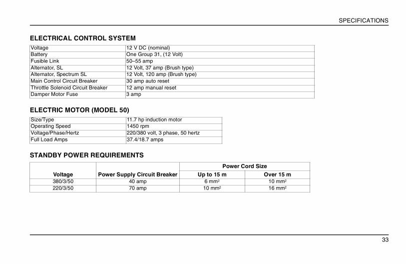
ELECTRICAL CONTROL SYSTEMVoltage 12 V DC (nominal)Battery One Group 31, (12 Volt)Fusible Link 50–55 ampAlternator, SL 12 Volt, 37 amp (Brush type)Alternator, Spectrum SL 12 Volt, 120 amp (Brush type)Main Control Circuit Breaker 30 amp auto resetThrottle Solenoid Circuit Breaker 12 amp manual resetDamper Motor Fuse 3 amp
ELECTRIC MOTOR (MODEL 50)Size/Type 11.7 hp induction motorOperating Speed 1450 rpmVoltage/Phase/Hertz 220/380 volt, 3 phase, 50 hertzFull Load Amps 37.4/18.7 amps
STANDBY POWER REQUIREMENTS
Voltage Power Supply Circuit BreakerPower Cord Size
Up to 15 m Over 15 m380/3/50 40 amp 6 mm2 10 mm2
220/3/50 70 amp 10 mm2 16 mm2

34
SPECIFICATIONS
35
SAFETY DECALS AND SERIAL NUMBERS
SAFETY DECALS AND SERIAL NUMBERS
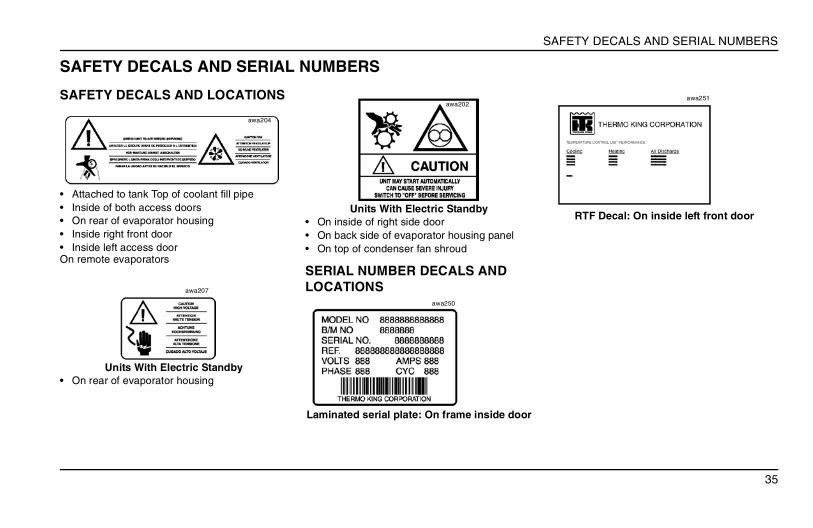
SAFETY DECALS AND LOCATIONS
• Attached to tank Top of coolant fill pipe• Inside of both access doors• On rear of evaporator housing• Inside right front door• Inside left access doorOn remote evaporators
Units With Electric Standby• On rear of evaporator housing
Units With Electric Standby• On inside of right side door• On back side of evaporator housing panel• On top of condenser fan shroud
SERIAL NUMBER DECALS AND LOCATIONS
Laminated serial plate: On frame inside door
RTF Decal: On inside left front door
awa204
awa207
awa202
awa250
awa251
36
SAFETY DECALS AND SERIAL NUMBERS
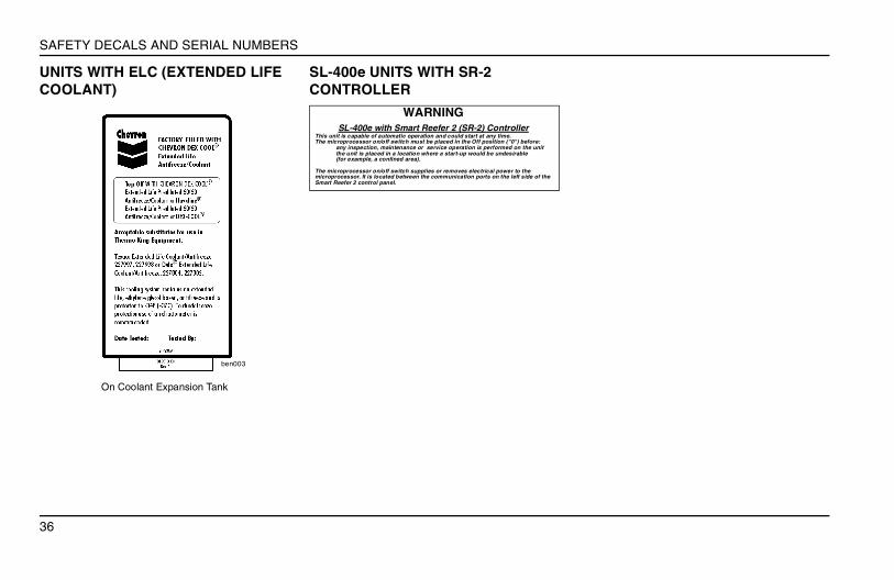
UNITS WITH ELC (EXTENDED LIFE COOLANT)
On Coolant Expansion Tank
SL-400e UNITS WITH SR-2 CONTROLLER
ben003
WARNINGSL-400e with Smart Reefer 2 (SR-2) Controller
This unit is capable of automatic operation and could start at any time. The microprocessor on/off switch must be placed in the Off position ("0") before:
any inspection, maintenance or service operation is performed on the unitthe unit is placed in a location where a start-up would be undesirable (for example, a confined area).
The microprocessor on/off switch supplies or removes electrical power to the microprocessor. It is located between the communication ports on the left side of the Smart Reefer 2 control panel.
37
WARRANTY
WARRANTYShould you require warranty service during the warranty period, simply present your copy of the Warranty Certificate at any of the dealer locations shown in the Thermo King Service Directory. They will be happy to help you in accordance with the summary below.
WARRANTY COVERAGE: DIESEL TRUCK AND TRAILER PRODUCTSFirst year warranty covers complete unit.Second year major components warranty covers specified components.
WARRANTY SUMMARY: DIESEL TRUCK AND TRAILER PRODUCTSSpecific terms of the Thermo King Ireland Ltd. 24 month Limited Warranty (TK 52506-9-CH) are available on request. Thermo King excludes liability in contract and tort (including strict liability and negligence) for any special, indirect or consequential damages by reason of the installation or use of any covered product or its mechanical failure.

38
WARRANTY
39
DECLARATIONS OF CONFORMITY
DECLARATIONS OF CONFORMITY
We, Thermo Kingof Monivea Road, Mervue, Galway, Ireland
are an Authorised Representative and declare under our sole responsibility that the SL Series Transport Refrigeration Units, carrying the registered brandname, THERMO KING conforms with the following standards:
EN292-1: 1993 Safety of MachineryEN292-2: 1995 Safety of MachineryEN294: 1994 Safety DistancesEN349: 1993 Minimum GapsEN378-1/2/3/4: 1994 Mobile (& other) Refrigerating SystemsEN60034-1: 1996 Rotating Electrical MachinesEN60034-7: 1993 Rotating Electrical Machines ConstructionEN50082-1: 1992 Electromagnetic Compatibility—Generic Immunity StandardEN50081-1: 1992 Electromagnetic Compatibility—Generic Emission StandardEN60204-1: 1998 Safety of Machinery - Electrical Equipment
Following the provisions of A) Machinery Directive 89/392/EEC (As Amended)B) EMC Directive 89/336/EEC and amendments 92/31 and 93/68.C) Low Voltage Directive 93/68/EEC (Amending Original).D) Pressure Equipment Directive 97/23/EC (Category 1, Module A, Assemblies).
Thermo King, Galway, Ireland
Pat KenneallyThermo King Galway Engineering Manager
Date: June 2004
40
DECLARATIONS OF CONFORMITY
DECLARATION OF CONFORMITY WITH EC DIRECTIVE 2000/14/EC
* Machines with the same two or three letter prefix have the same sound poower as the principal noise producing components and running speeds are the same.
Thermo King Europe, Ltd. Monivea Road Mervue, Galway IRELAND
Thermo King Europe, Ltd. declare that the following transport refrigeration units have been manufactured in conformance with Directive 2000/14/EC as shown
Directive Machine Max. Engine RPM
Effective from Serial Numbers:
Maximum Measured Value
Guaranteed Level
(Sound Power, dBA)2000/14/EC Annex V SL-100 & SL-100e 1600 012xxxxxxx 99 LWA 103 LWA
SL-200 & SL-200e 1900 012xxxxxxx 100 LWA 103 LWASL-400 & SL-400e 2200 012xxxxxxx 100 LWA 103 LWA
Spectrum SL 2200 012xxxxxxx 100 LWA 103 LWASB-III DE 2200 012xxxxxxx 103 LWA 106 LWASB-III CR 1600 012xxxxxxx 96 LWA 99 LWA