
USER MANUAL DR-SERIES PYRHELIOMETERS · PDF fileOptionally the instrument may be ordered with...
47
Copyright by Hukseflux | manual v1609 | www.hukseflux.com | [email protected] USER MANUAL DR-SERIES PYRHELIOMETERS First class pyrheliometer DR01 Fast response first class pyrheliometer DR02 Compact fast response first class pyrheliometer DR03 Hukseflux Thermal Sensors
-
Upload
nguyenkiet -
Category
Documents
-
view
226 -
download
0
Transcript of USER MANUAL DR-SERIES PYRHELIOMETERS · PDF fileOptionally the instrument may be ordered with...
Copyright by Hukseflux | manual v1609 | www.hukseflux.com | [email protected]
USER MANUAL DR-SERIES PYRHELIOMETERS
First class pyrheliometer DR01 Fast response first class pyrheliometer DR02
Compact fast response first class pyrheliometer DR03
HuksefluxThermal Sensors

DR01 DR02 DR03 manual v1609 2/47
Warning statements
Putting more than 12 Volt across the sensor wiring can lead to permanent damage to the sensor. Do not use “open circuit detection” when measuring the sensor output.
DR01 DR02 DR03 manual v1609 3/47
Contents Warning statements 2 Contents 3 List of symbols 4 Introduction 5 1 Ordering and checking at delivery 7 1.1 Ordering DR01, DR02 and DR03 7 1.2 Included items 7 1.3 Quick instrument check 8 2 Instrument principle and theory 9 3 Specifications of DR01 / DR02 / DR03 11 3.1 Specifications 11 3.2 Dimensions of DR01 & DR02 15 4 Standards and recommended practices for use 16 4.1 Classification standard 16 4.2 General use for solar radiation measurement 16 4.3 General use for sunshine duration measurement 17 4.4 Specific use in meteorology and climatology 17 5 Installation of pyrheliometers 18 5.1 Site selection and installation 18 5.2 Installation of the protection cap 18 5.3 Electrical connection 19 5.4 Requirements for data acquisition / amplification 20 6 Making a dependable measurement 21 6.1 The concept of dependability 21 6.2 Reliability of the measurement 22 6.3 Speed of repair and maintenance 23 6.4 Uncertainty evaluation 23 7 Maintenance and trouble shooting 28 7.1 Recommended maintenance and quality assurance 28 7.2 Trouble shooting 29 7.3 Calibration and checks in the field 30 7.4 Data quality assurance 30 8 DR03 31 8.1 Introduction DR03 31 8.2 Dimensions of DR03 32 9 Appendices 34 9.1 Appendix on cable extension / replacement 34 9.2 Appendix on optional chassis connector & cable connector 35 9.3 Appendix on tools for DR01 / DR02 / DR03 35 9.4 Appendix on spare parts for DR01 / DR02/ DR03 35 9.5 Appendix on standards for classification and calibration 36 9.6 Appendix on calibration hierarchy 37 9.7 Appendix on requirements for solar tracking 38 9.8 Appendix on meteorological radiation quantities 39 9.9 Appendix on ISO and WMO classification tables 40 9.10 Appendix on definition of pyrheliometer specifications 42 9.11 Appendix on terminology / glossary 43 9.12 Appendix on literature references 45 9.13 EC declaration of conformity 46
DR01 DR02 DR03 manual v1609 4/47
List of symbols Quantities Symbol Unit Voltage output U V Sensitivity S V/(W/m2) Solar irradiance E W/m2 (see also appendix 9.8 on meteorological quantities) Subscripts Not applicable

DR01 DR02 DR03 manual v1609 5/47
Introduction DR01, DR02 and DR03 are high-accuracy direct normal irradiance (DNI) solar radiation sensors, also known as pyrheliometers. The DR-series pyrheliometers comply with the ‘first class’ specifications of the ISO 9060 standard and the ‘good quality’ performance level of WMO’s No. 8 Guide. Pyrheliometers are typically mounted on a solar tracker. A unique product feature of all pyrheliometers in the DR-series is the heated window. DR02 and DR03 are the fast-response versions of DR01. The difference is in detector technology, resulting in a much faster response time (95 %) for DR02 and DR03: 2 s instead of the traditional 12 s. DR02 has the same body and dimensions as DR01. DR03 is a compact version of DR02 pyrheliometer. This manual is written for the standard model DR01; DR02 and DR03 specifications and operation are mentioned only in case these differ from DR01’s. DR03, with its different dimensions, has a dedicated chapter in this manual. Figure 0.1 DR01 / DR02 pyrheliometer Figure 0.2 DR03 pyrheliometer DR01 is a solar radiation sensor that is applied in high accuracy observations. It measures the solar radiation received by a plane surface from a 5 ° full field of view angle. This quantity, expressed in W/m2, is called ‘direct’ solar radiation or direct normal irradiance (DNI). Pyrheliometers are generally employed outdoors under the sun. It is necessary to keep the instrument pointed at the sun by using a two-axis tracker. Typical DR01 applications include solar energy resource assessment, system performance monitoring (in particular for concentrated solar energy) and scientific solar climate observations. DR01 pyrheliometer features a precision ground and polished quartz window, a collimated tube and a thermopile sensor with black coated surface. It has an anodised
DR01 DR02 DR03 manual v1609 6/47
aluminium body. DR01 also features a thermally isolated low-power heater in the window assembly. The heater increases data availability, for instance by reducing measurement errors caused by (early-morning) dew deposition. DR01 pyrheliometer is optionally equipped with a temperature sensor and is optionally characterised for its temperature response. This can be used to increase the accuracy of the measurement. Using DR01 is easy. It can be connected directly to commonly used data logging systems. The irradiance, E, in W/m2 is calculated by dividing the DR01 output, a small voltage U, by the sensitivity S. The sensitivity is provided with DR01 on its calibration certificate. The central equation governing DR01 is: E = U/S (Formula 0.1) A pyrheliometer can also be used to measure sunshine duration. Sunshine duration during a given period is defined as the sum of that sub-period for which the direct solar irradiance exceeds 120 W/m2. Suggested use for DR01: • outdoor PV / CPV and CSP system performance monitoring • solar energy surveys • solar resource assessments • meteorological networks
Applicable instrument classification standards are ISO 9060 and WMO-No. 8. Calibration is traceable to WRR (World Radiometric Reference). The instrument should be used in accordance with the recommended practices of ISO, WMO and ASTM. Various tracking solutions can be offered by Hukseflux. Please contact us for more information on solar trackers.
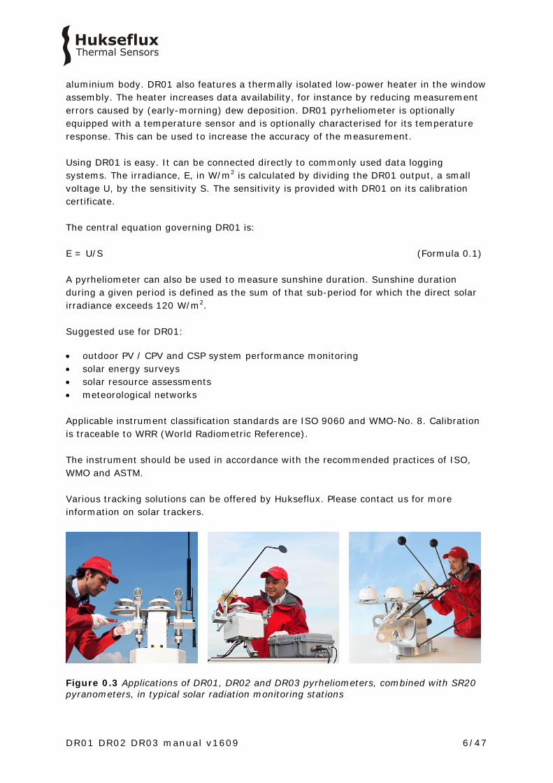
Figure 0.3 Applications of DR01, DR02 and DR03 pyrheliometers, combined with SR20 pyranometers, in typical solar radiation monitoring stations

DR01 DR02 DR03 manual v1609 7/47
1 Ordering and checking at delivery
1.1 Ordering DR01, DR02 and DR03
The standard configuration of DR01 is with 5 metres cable. Common options are: • Longer cable in multiples of 5 m, cable lengths above 20 m in multiples of 10 m.
Specify total cable length. • Internal temperature sensor. This can be either a Pt100 or a 10 kΩ thermistor.
Specify respectively T1 or T2. • Five silica gel bags in an air-thight bag for desiccant holder. Specify part number
DC01. • Temperature dependence characterisation • Improved temperature response
Standard DR01 / DR02 / DR03 pyrheliometers are equipped with a cable with cable gland. Optionally the instrument may be ordered with a chassis connector and a cable with connector. Please consult Hukseflux.
1.2 Included items
Arriving at the customer, the delivery should include: • pyrheliometer DR01 / DR02 / DR03 • cable of the length as ordered • product certificate matching the instrument serial number • any other options as ordered Please store the certificate in a safe place.

DR01 DR02 DR03 manual v1609 8/47
1.3 Quick instrument check
A quick test of the instrument can be done by using a simple hand held multimeter and a lamp. 1. Check the electrical resistance of the sensor between the green (-) and white (+) wire. See chapter 5.3 on electrical connections. Use a multimeter at the 1000 Ω range. Measure the sensor resistance first with one polarity, than reverse the polarity. Take the average value. The typical resistance of the wiring is 0.1 Ω/m. Typical resistance should be the typical sensor resistance of 400 to 500 Ω for DR01 and 150 to 250 Ω for DR02 and DR03, plus 1.5 Ω for the total resistance of two wires (back and forth) of each 5 m. Infinite resistance indicates a broken circuit; zero or a low resistance indicates a short circuit. 2. Check if the sensor reacts to light: put the multimeter at its most sensitive range of DC voltage measurement, typically the 100 x 10-3 VDC range or lower. Expose the sensor to a strong light source, for instance a 100 W light bulb at the front window. The signal should read > 2 x 10⁻³ V now. Darken the sensor either by putting something over it or switching off the light. The instrument voltage output should go down and within one minute approach 0 V. 3. Inspect the instrument for any damage. Check if the sight is straight and aligned. 4. Inspect if the humidity indicator is blue. The colour pink indicates it is not dry but humid: in the latter case replace the desiccant (see chapter on maintenance). 5. Optional: inspect the electrical resistance range of the internal temperature sensors (for Pt100 in the 100 Ω range, for 10 kΩ thermistors in the 10 000 Ω range, in case of 3 wire or 4 wire connections of the Pt100 in the < 10 Ω range between connections at one end). Figure 1.3.1 DR01 first class pyrheliometer

DR01 DR02 DR03 manual v1609 9/47
2 Instrument principle and theory
Figure 2.1 Overview of DR01: (1) humidity indicator (2) sights (3) aperture tube (4) protection cap (5) window assembly with heater (6) cable gland (7) cable (standard length 5 metres cable, optional longer cable) DR01’s scientific name is pyrheliometer. It measures the solar radiation received by a plane surface from a 5 ° full field of view angle. In addition to the full field of view angle, (the angle from the centre of the sensor to the edge of the aperture window) WMO recommends in WMO manual 7.2 a slope angle (the angle from the side of the sensor to the edge of the window aperture) of 1 °. The opening angle and slope angle together with the sensor surface define the so-called acceptance function (see appendix on terminology). A pyrheliometer should measure ‘direct’ solar radiation, also called direct normal irradiance or DNI. DNI is defined as the solar radiant flux collected by a plane unit surface normal to the axis pointing towards the centre of the sun, within an optical angular aperture. This aperture is characterized by the acceptance function (ref: IEA SHC #46 and EU FP7 MACC-II projects, published by Blanc et al. (2014), see appendix on terminology and appendix on literature references). DNI is composed of the solar irradiance within the extent of the solar disk (half-angle 0.266 ° ± 1.7 %) plus some circumsolar radiation.
1
23
2 4
5
67

DR01 DR02 DR03 manual v1609 10/47
Summarising, DR01 is a radiometer designed to measure DNI (i.e. including some circumsolar irradiance). It complies with the WMO recommended parameters for the view-limiting geometry: a full opening angle of 5 °, and a slope angle of 1 °, and therefore a limit angle of 4 °. The solar radiation spectrum extends roughly from 285 to 3000 x 10-9 m. By definition a pyrheliometer should cover that spectral range with a spectral selectivity that is as “flat” as possible. For a correct measurement DR01 should be pointed at the sun. It is usually mounted on a solar tracker. For tracking requirements see the appendix on solar tracking. In order to attain the proper directional and spectral characteristics, DR01 pyrheliometer’s main components are: • a thermal sensor with black coating. It has a flat spectrum covering the 200 to 4000
x 10-9 m range. The coating absorbs all solar radiation and, at the moment of absorption, converts it to heat. The heat flows through the sensor to the instrument body. The thermopile sensor generates a voltage output signal that is proportional to the solar irradiance.
• a quartz glass window. This window limits the spectral range from 200 to 4000 x 10-9 m (cutting off the part above 4000 x 10-9 m)
• an aperture tube. The most important components of this tube are two apertures. One at the detector and the other at the front window. These determine the opening- and slope angle.
• A heater incorporated in the window assembly. This reduces measurement errors caused by (early-morning) dew deposition. Typically the heater is switched on at night only. Some users have employed the heater in high-power operation to counter frost deposition.
Pyrheliometers can be manufactured to different specifications and with different levels of verification and characterisation during production. The ISO 9060 - 1990 standard, “Solar energy - specification and classification of instruments for measuring hemispherical solar and direct solar radiation”, distinguishes between 3 classes; secondary standard (highest accuracy), first class (second highest accuracy) and second class (third highest accuracy). Due to the required spectral selectivity a secondary standard pyrheliometer can only be made with a cavity-type sensor. In addition the calibration of a secondary standard pyrheliometer must be done by periodic comparison with a primary standard radiometer. For this reason commercially available thermopile pyrheliometers with a flat detector and a window can only be first-class. From first class to secondary standard, the achievable accuracy improves by a factor 2.

DR01 DR02 DR03 manual v1609 11/47
3 Specifications of DR01 / DR02 / DR03
3.1 Specifications
DR01 measures the solar radiation received by a plane surface from a from a 5 ° full field of view angle and a 1 ° slope angle, i.e. the acceptance function recommended by WMO. This quantity, expressed in W/m2, is called ‘direct’ solar radiation or direct normal irradiance (DNI). DNI can be used to calculate sunshine duration. Working completely passive, using a thermopile sensor, DR01 generates a small output voltage proportional to this flux. It can only be used in combination with a suitable measurement system and a solar tracker to keep it continuously aimed at the sun. The window assembly contains a heater which may be activated to prevent dew deposition. The instrument is classified according to ISO 9060 and should be used in accordance with the recommended practices of ISO, IEC, WMO and ASTM. DR02 and DR03 are fast-response versions of DR01. DR03 is a compact version of DR02. Table 3.1.1 Specifications of DR01 / DR02 / DR03 (continued on next pages) DR01 / DR02 / DR03 MEASUREMENT SPECIFICTIONS: LIST OF CLASSIFICATION CRITERIA OF ISO 9060* ISO classification (ISO 9060: 1990) first class pyrheliometer WMO performance level (WMO-No-8, seventh edition 2008)
good quality pyrheliometer
Response time (95 %) DR01: 12 s (nominal) DR02: 2 s (nominal) DR03: 2 s (nominal)
Zero offset (response to 5 K/h change in ambient temperature)
< ± 1 W/m2
Non-stability < ± 0.5 % change per year Non-Linearity < ± 0.3 % (100 to 1000 W/m2) Full field of view angle 5 ° Slope angle 1 ° Limit angle 4 ° (follows from full field of view angle and slope angle) Spectral selectivity < ± 1 % (0.35 to 1.5 x 10⁻⁶ m) Temperature response < ± 1 % (-10 to +40 °C)
< ± 0.4 % (-30 to +50 °C)** ** with correction in dataprocessing if opted for internal temperature sensor + temperature dependence characterisation (see options)
Tilt response < ± 0.5 % (0 to 90 ° at 1000 W/m2) *For the exact definition of pyrheliometer ISO 9060 specifications see the appendix.
DR01 DR02 DR03 manual v1609 12/47
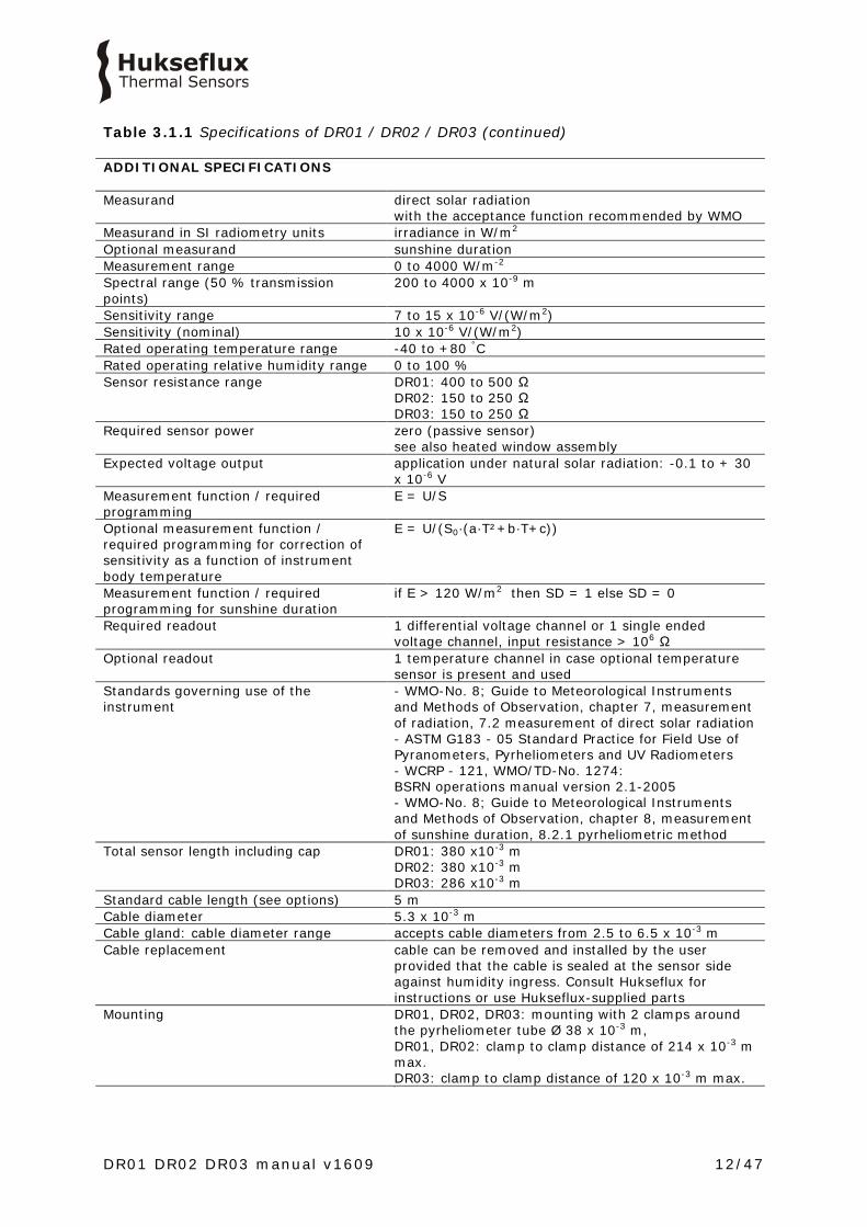
Table 3.1.1 Specifications of DR01 / DR02 / DR03 (continued) ADDITIONAL SPECIFICATIONS Measurand direct solar radiation
with the acceptance function recommended by WMO Measurand in SI radiometry units irradiance in W/m2 Optional measurand sunshine duration Measurement range 0 to 4000 W/m-2 Spectral range (50 % transmission points)
200 to 4000 x 10-9 m
Sensitivity range 7 to 15 x 10-6 V/(W/m2) Sensitivity (nominal) 10 x 10-6 V/(W/m2) Rated operating temperature range -40 to +80 °C Rated operating relative humidity range 0 to 100 % Sensor resistance range DR01: 400 to 500 Ω
DR02: 150 to 250 Ω DR03: 150 to 250 Ω
Required sensor power zero (passive sensor) see also heated window assembly
Expected voltage output application under natural solar radiation: -0.1 to + 30 x 10-6 V
Measurement function / required programming
E = U/S
Optional measurement function / required programming for correction of sensitivity as a function of instrument body temperature
E = U/(S0·(a·T²+b·T+c))
Measurement function / required programming for sunshine duration
if E > 120 W/m2 then SD = 1 else SD = 0
Required readout 1 differential voltage channel or 1 single ended voltage channel, input resistance > 106 Ω
Optional readout 1 temperature channel in case optional temperature sensor is present and used
Standards governing use of the instrument
- WMO-No. 8; Guide to Meteorological Instruments and Methods of Observation, chapter 7, measurement of radiation, 7.2 measurement of direct solar radiation - ASTM G183 - 05 Standard Practice for Field Use of Pyranometers, Pyrheliometers and UV Radiometers - WCRP - 121, WMO/TD-No. 1274: BSRN operations manual version 2.1-2005 - WMO-No. 8; Guide to Meteorological Instruments and Methods of Observation, chapter 8, measurement of sunshine duration, 8.2.1 pyrheliometric method
Total sensor length including cap DR01: 380 x10-3 m DR02: 380 x10-3 m DR03: 286 x10-3 m
Standard cable length (see options) 5 m Cable diameter 5.3 x 10⁻³ m Cable gland: cable diameter range accepts cable diameters from 2.5 to 6.5 x 10⁻³ m Cable replacement cable can be removed and installed by the user
provided that the cable is sealed at the sensor side against humidity ingress. Consult Hukseflux for instructions or use Hukseflux-supplied parts
Mounting DR01, DR02, DR03: mounting with 2 clamps around the pyrheliometer tube Ø 38 x 10-3 m, DR01, DR02: clamp to clamp distance of 214 x 10-3 m max. DR03: clamp to clamp distance of 120 x 10-3 m max.
. .

DR01 DR02 DR03 manual v1609 13/47
Table 3.1.1 Specifications of DR01 / DR02 / DR03 (continued) IP protection class IP67 Desiccant Two bags of silica gel, 0.5 g, (35 x 20) x 10-3 m Recommended desiccant replacement interval
2 years (typically at the moment of calibration)
Humidity indicator blue when dry, pink when humid SHIPPING
Gross weight including 5 m cable 1.0 kg Net weight including 5 m cable DR01: 0.9 kg
DR02: 0.9 kg DR03: 0.8 kg
Packaging box of (430x105x105) x 10-3 m TRACKING AND ALIGNMENT
Required tracking the instrument must be pointed at the sun centre Required alignment the pyrheliometer and the tracker should be aligned
using the pyrheliometer sight Rated misalignment interval (without impact on measurement accuracy)
DR01: ± 0.5 ° DR02: ± 0.5 ° DR03: ± 0.3 ° from the sun centre, using the pyrheliometer sight as a reference
Sight resolution DR01: < 0.2 ° DR02: < 0.2 ° DR03: < 0.4 ° lightspot projection < 25 % off target hole
Sight sensitivity DR01: 4 x 10⁻³ m/° DR02: 4 x 10⁻³ m/° DR03: 2 x 10⁻³ m/°
WINDOW ASSEMBLY WITH HEATER Window assembly with heater 12 VDC, 0.5 W Heater operation the heater is not necessarily switched on;
recommended operation is to activate the heater when the sun is below the horizon
Heater resistance 272 Ω Steady state zero offset caused by 0.5W heating
< 1 W/m2
Optional high power operation of the heater to rapidly remove frost
24 VDC, 2 W
Steady state zero offset caused by high power 2 W heating
< 4 W/m2
CALIBRATION
Calibration traceability to WRR Calibration hierarchy from WRR through ISO 9059, applying a correction to
reference conditions Calibration method indoor comparison to a reference pyrheliometer Calibration uncertainty < 1.2 % (k = 2) Recommended recalibration interval 2 years Reference conditions 20 °C, horizontal mounting , irradiance level 1000
W/m2 Validity of calibration
based on experience the instrument sensitivity will not change during storage. During use under exposure to solar radiation the instrument “non-stability” specification is applicable.

DR01 DR02 DR03 manual v1609 14/47
Table 3.1.1 Specifications of DR01/DR02/DR03 (started on previous pages) MEASUREMENT ACCURACY Uncertainty of the measurement statements about the overall measurement
uncertainty can only be made on an individual basis. See the chapter on uncertainty evaluation
WMO ESTIMATE OF ACHIEVABLE MEASUREMENT UNCERTAINTY Minute totals ± 1.8 % (k = 2)
(under typical conditions, well maintained, not taking calibration uncertainty into account)
Hourly totals ± 1.5 % (k = 2) (under typical conditions, well maintained, not taking calibration uncertainty into account)
Daily totals ± 1.0 % (k = 2) (under typical conditions, well maintained, not taking calibration uncertainty into account)
VERSIONS / OPTIONS
Internal temperature sensor measuring the body temperature: version code = T1 for Pt100 DIN class A, version code = T2 for thermistor 10 kΩ at 25 °C
longer cable, in multiples of 5 m, cable lengths above 20 m in multiples of 10 m
option code = total cable length
Temperature dependence characterisation
option code = TRC < ± 1 % (-10 to +40 °C) < ± 0.4 % (-30 to +50 °C) with correction in dataprocessing
Improved temperature response includes TRC option code = ITR < ± 0.5 % (-20 to +50 °C) < ± 0.4 % (-30 to +50 °C) with correction in dataprocessing
Adapted sensitivity range DR01 only: the sensitivity range can be adapted to customer requirements (to a lower range only) option code = lower end - higher end of the allowed range x 10-6 V/(W/m2)
Chassis connector and cable with connector
M16 panel connector, male thread, 10-pole Cable with M16 straight connector, female thread, 10-pole option code = C
ACCESSORIES
Protection cap spare protection cap Bags of silica gel for desiccant set of 5 bags in an air tight bag
option code = DC01

DR01 DR02 DR03 manual v1609 15/47
3.2 Dimensions of DR01 & DR02
Figure 3.2.1 Dimensions of DR01 and DR02 in x 10-3 m. For DR03 dimensions see the dedicated chapter on DR03.
380
215
50
Ø 3
8
DR01 DR02 DR03 manual v1609 16/47
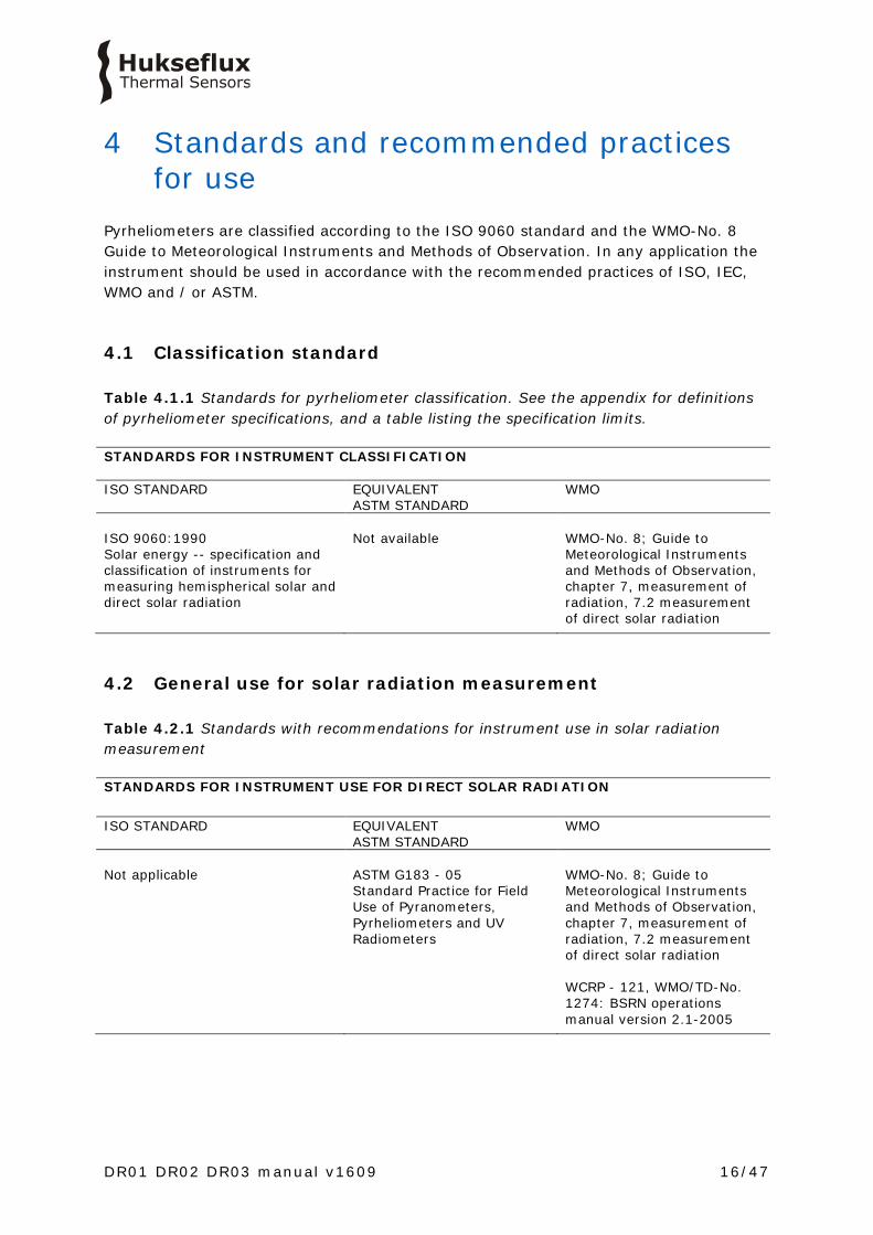
4 Standards and recommended practices for use
Pyrheliometers are classified according to the ISO 9060 standard and the WMO-No. 8 Guide to Meteorological Instruments and Methods of Observation. In any application the instrument should be used in accordance with the recommended practices of ISO, IEC, WMO and / or ASTM.
4.1 Classification standard Table 4.1.1 Standards for pyrheliometer classification. See the appendix for definitions of pyrheliometer specifications, and a table listing the specification limits. STANDARDS FOR INSTRUMENT CLASSIFICATION ISO STANDARD EQUIVALENT
ASTM STANDARD WMO
ISO 9060:1990 Solar energy -- specification and classification of instruments for measuring hemispherical solar and direct solar radiation
Not available
WMO-No. 8; Guide to Meteorological Instruments and Methods of Observation, chapter 7, measurement of radiation, 7.2 measurement of direct solar radiation
4.2 General use for solar radiation measurement Table 4.2.1 Standards with recommendations for instrument use in solar radiation measurement STANDARDS FOR INSTRUMENT USE FOR DIRECT SOLAR RADIATION ISO STANDARD EQUIVALENT
ASTM STANDARD WMO
Not applicable
ASTM G183 - 05 Standard Practice for Field Use of Pyranometers, Pyrheliometers and UV Radiometers
WMO-No. 8; Guide to Meteorological Instruments and Methods of Observation, chapter 7, measurement of radiation, 7.2 measurement of direct solar radiation WCRP - 121, WMO/TD-No. 1274: BSRN operations manual version 2.1-2005
DR01 DR02 DR03 manual v1609 17/47
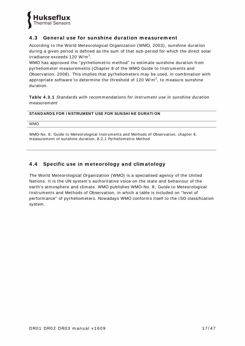
4.3 General use for sunshine duration measurement According to the World Meteorological Organization (WMO, 2003), sunshine duration during a given period is defined as the sum of that sub-period for which the direct solar irradiance exceeds 120 W/m2. WMO has approved the “pyrheliometric method” to estimate sunshine duration from pyrheliometer measurements (Chapter 8 of the WMO Guide to Instruments and Observation, 2008). This implies that pyrheliometers may be used, in combination with appropriate software to determine the threshold of 120 W/m2, to measure sunshine duration. Table 4.3.1 Standards with recommendations for instrument use in sunshine duration measurement STANDARDS FOR INSTRUMENT USE FOR SUNSHINE DURATION WMO WMO-No. 8; Guide to Meteorological Instruments and Methods of Observation, chapter 8, measurement of sunshine duration, 8.2.1 Pyrheliometric Method
4.4 Specific use in meteorology and climatology
The World Meteorological Organization (WMO) is a specialised agency of the United Nations. It is the UN system's authoritative voice on the state and behaviour of the earth's atmosphere and climate. WMO publishes WMO-No. 8; Guide to Meteorological Instruments and Methods of Observation, in which a table is included on “level of performance” of pyrheliometers. Nowadays WMO conforms itself to the ISO classification system.
DR01 DR02 DR03 manual v1609 18/47
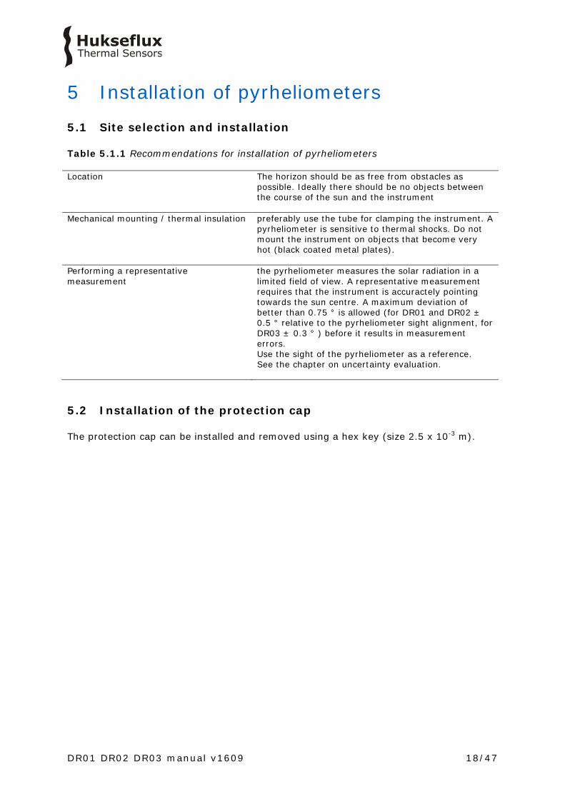
5 Installation of pyrheliometers
5.1 Site selection and installation
Table 5.1.1 Recommendations for installation of pyrheliometers Location The horizon should be as free from obstacles as
possible. Ideally there should be no objects between the course of the sun and the instrument
Mechanical mounting / thermal insulation
preferably use the tube for clamping the instrument. A pyrheliometer is sensitive to thermal shocks. Do not mount the instrument on objects that become very hot (black coated metal plates).
Performing a representative measurement
the pyrheliometer measures the solar radiation in a limited field of view. A representative measurement requires that the instrument is accuractely pointing towards the sun centre. A maximum deviation of better than 0.75 ° is allowed (for DR01 and DR02 ± 0.5 ° relative to the pyrheliometer sight alignment, for DR03 ± 0.3 ° ) before it results in measurement errors. Use the sight of the pyrheliometer as a reference. See the chapter on uncertainty evaluation.
5.2 Installation of the protection cap
The protection cap can be installed and removed using a hex key (size 2.5 x 10⁻³ m).

DR01 DR02 DR03 manual v1609 19/47
5.3 Electrical connection In order to operate, a pyrheliometer should be connected to a measurement system, typically a so-called datalogger. DR01 employs a passive sensor that does not need any power. In case the heater is used, it consumes 1.5 W at 12 VDC. Cables generally act as a source of distortion, by picking up capacitive noise. We recommend keeping the distance between a datalogger or amplifier and the sensor as short as possible. For cable extension, see the appendix on this subject. The wiring electrical connection of your instrument can be found on its product certificate. Table 5.3.1 The electrical connection of DR01. In the standard DR01, only the signal and heater wires are used. The table also shows connection of optional versions T1 and T2. The heater is not necessarily used. The temperature sensor is not necessarily used.
PIN WIRE DR01 DR01-T1 DR01-T2
1 Red Pt100 [+] 10 kΩ thermistor [+]
2 Brown Pt100 [+] 10 kΩ thermistor [+]
3 Yellow Pt100 [−] 10 kΩ thermistor [−]
4 Blue Pt100 [−] 10 kΩ thermistor [−]
5 Pink heater heater heater
6 Grey heater heater heater
7 Green signal [−] signal [−] signal [−]
8 White signal [+] signal [+] signal [+]
9 Black ground ground ground
Note 1: Pt100’s of optional version T1 may be connected in a 3-wire or 4-wire configuration. Note 2: 10 kΩ thermistors of optional version T2 are usually connected in a 2-wire configuration. Note 3: the heater is not necessarily connected. In case it is connected, the polarity of the connection is not significant. Note 4: signal wires are insulated from ground wire and from the sensor body. Insulation resistance is tested during production and larger than 1 x 10⁶ Ω. Note 5: Ground is connected to the instrument body and the shield of the cable.
DR01 DR02 DR03 manual v1609 20/47
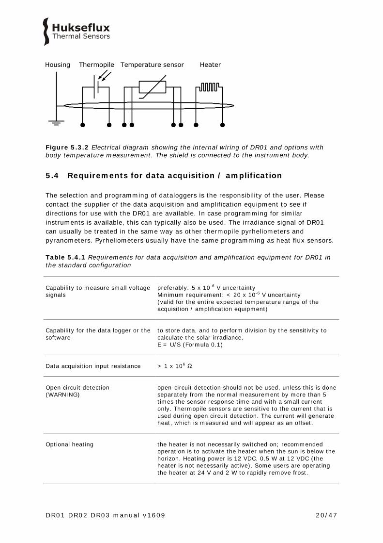
Figure 5.3.2 Electrical diagram showing the internal wiring of DR01 and options with body temperature measurement. The shield is connected to the instrument body.
5.4 Requirements for data acquisition / amplification The selection and programming of dataloggers is the responsibility of the user. Please contact the supplier of the data acquisition and amplification equipment to see if directions for use with the DR01 are available. In case programming for similar instruments is available, this can typically also be used. The irradiance signal of DR01 can usually be treated in the same way as other thermopile pyrheliometers and pyranometers. Pyrheliometers usually have the same programming as heat flux sensors. Table 5.4.1 Requirements for data acquisition and amplification equipment for DR01 in the standard configuration Capability to measure small voltage signals
preferably: 5 x 10⁻⁶ V uncertainty Minimum requirement: < 20 x 10-6 V uncertainty (valid for the entire expected temperature range of the acquisition / amplification equipment)
Capability for the data logger or the software
to store data, and to perform division by the sensitivity to calculate the solar irradiance. E = U/S (Formula 0.1)
Data acquisition input resistance
> 1 x 10⁶ Ω
Open circuit detection (WARNING)
open-circuit detection should not be used, unless this is done separately from the normal measurement by more than 5 times the sensor response time and with a small current only. Thermopile sensors are sensitive to the current that is used during open circuit detection. The current will generate heat, which is measured and will appear as an offset.
Optional heating
the heater is not necessarily switched on; recommended operation is to activate the heater when the sun is below the horizon. Heating power is 12 VDC, 0.5 W at 12 VDC (the heater is not necessarily active). Some users are operating the heater at 24 V and 2 W to rapidly remove frost.

DR01 DR02 DR03 manual v1609 21/47
6 Making a dependable measurement
6.1 The concept of dependability A measurement with a pyrheliometer is called “dependable” if it is reliable, i.e. measuring within required uncertainty limits, for most of the time and if problems, once they occur, can be solved quickly. The requirements for a measurement with a pyrheliometer may be expressed by the user as: • required uncertainty of the measurement (see following paragraphs) • requirements for maintenance and repairs (possibilities for maintenance and repair
including the effort to be made and the processing time) • a requirement to the expected instrument lifetime (until it is no longer feasible to
repair) It is important to realise that the uncertainty of the measurement is not only determined by the instrument but also by the way it is used. See also ISO 9060 note 5. In case of pyrheliometers, the measurement uncertainty as obtained during outdoor measurements is a function of: • the instrument class • the calibration procedure / uncertainty • the duration of instrument employment under natural sunlight (involving the
instrument stability specification) • the measurement conditions (such as tilting, ventilation, shading, instrument
temperature) • maintenance (cleaning of the window and verification of the alignment accuracy) • the environmental conditions (such as atmospheric aerosol content, ambient air
temperature, position of the sun, presence of clouds, horizon, representativeness of the location)*
Therefore, ISO 9060 says, “statements about the overall measurement uncertainty under outdoor conditions can only be made on an individual basis, taking all these factors into account”. * defined at Hukseflux as all factors outside the instrument that are relevant to the measurement such as the cloud cover (presence or absence of direct radiation), sun position, the local horizon (which may be obstructed). The environmental conditions also involve the question whether or not the measurement at the location of measurement is representative of the quantity that should be measured. For pyrheliometers the spatial distribution of circumsolar radiation, which is generated by optical scattering of direct solar radiation of the sun, may be included in uncertainty estimates. There is a contribution only in case there is a mismatch between the pyrheliometer’s acceptance function and the acceptance function defined for the measurand.
DR01 DR02 DR03 manual v1609 22/47
6.2 Reliability of the measurement A measurement is reliable if it measures within required uncertainty limits for most of the time. We distinguish between two causes of unreliability of the measurement: • related to the reliability of the pyrheliometer and its design, manufacturing,
calibration (hardware reliability). • related to the reliability of the measurement uncertainty (measurement reliability),
which involves hardware reliability as well as condition of use. Most of the hardware reliability is the responsibility of the instrument manufacturer. The reliability of the measurement however is a joint responsibility of instrument manufacturer and user. As a function of user requirements, taking into account measurement conditions and environmental conditions, the user will select an instrument of a certain class, and define maintenance support procedures. In many situations there is a limit to a realistically attainable accuracy level. This is due to conditions that are beyond control once the measurement system is in place. Typical limiting conditions are: • the measurement conditions, for instance when working at extreme temperatures
when the instrument temperature is at the extreme limits of the rated temperature range.
• the environmental conditions, for instance when installed at a sub-optimal measurement location with obstacles in the path of the sun.
The measurement reliability can be improved by maintenance support. Important aspects are: • window fouling by deposition of dust, dew, rain or snow. Fouling results in undefined
measurement uncertainty (sensitivity and acceptance function are no longer defined). This should be solved by regular inspection and cleaning.
• sensor instability. Maximum expected sensor aging is specified per instrument as its non-stability in [% change / year]. In case the sensor is not recalibrated, the uncertainty of the sensitivity gradually will increase. This is solved by regular recalibration.
• moisture condensing under the pyrheliometer window resulting in a slow change of sensitivity (within specifications). This is solved by regular replacement of desiccant or by maintenance (drying the entire sensor). For pyrheliometers extra desiccant (in a set of 5 bags in an air tight bag) is available.
Another way to improve measurement reliability is to introduce redundant sensors. • The use of redundant instruments allows remote checks of one instrument using the
other as a reference, which leads to a higher measurement reliability. • Data can also be compared to measurements by local meteorological stations. • DNI data can often be compared to pyranometer measurements (global irradiance
and diffuse), assessing the uncertainty by looking if the totals match up.

DR01 DR02 DR03 manual v1609 23/47
6.3 Speed of repair and maintenance
Dependability is not only a matter of reliability but also involves the reaction to problems; if the processing time of service and repairs is short, this contributes to the dependability. Hukseflux pyrheliometers are designed to allow easy maintenance and repair. The main maintenance actions are: • replacement of desiccant • replacement of cabling For optimisation of dependability a user should: • estimate the expected lifetime of the instrument • design a schedule of regular maintenance • design a schedule of repair or replacement in case of defects When operating multiple instruments in a network Hukseflux recommends keeping procedures simple and having a few spare instruments to act as replacements during service, recalibrations and repair.
6.4 Uncertainty evaluation The uncertainty of a measurement under outdoor or indoor conditions depends on many factors, see paragraph 1 of this chapter. It is not possible to give one figure for pyrheliometer measurement uncertainty. The work on uncertainty evaluation is “in progress”. There are several groups around the world participating in standardisation of the method of calculation. The effort aims to work according to the guidelines for uncertainty evaluation (according to the “Guide to Expression of Uncertainty in Measurement” or GUM).
6.4.1 Definition of the measurand DR01 measures direct solar radiation with an acceptance function as recommended by WMO (see also the appendix on the terminology). In most measurements related to meteorology, solar energy resource assessment and PV system performance monitoring, the required measurand equals the DR01 measurand. In that case the acceptance function is perfect and there is no contribution of the circumsolar radiation to the measurement uncertainty. However, in case the required measurand acceptance function is different from that recommended by WMO, for instance when estimating the input to Concentrated PV panels (CPV), this leads to additional measurement uncertainty. See the next paragraph of an idea of the order of magnitude.
DR01 DR02 DR03 manual v1609 24/47
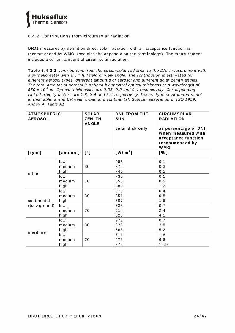
6.4.2 Contributions from circumsolar radiation DR01 measures by definition direct solar radiation with an acceptance function as recommended by WMO. (see also the appendix on the terminology). The measurement includes a certain amount of circumsolar radiation. Table 6.4.2.1 contributions from the circumsolar radiation to the DNI measurement with a pyrheliometer with a 5 ° full field of view angle. The contribution is estimated for different aerosol types, different amounts of aerosol and different solar zenith angles. The total amount of aerosol is defined by spectral optical thickness at a wavelength of 550 x 10-9 m. Optical thicknesses are 0.05, 0.2 and 0.4 respectively. Corresponding Linke turbidity factors are 1.8, 3.4 and 5.4 respectively. Desert-type environments, not in this table, are in between urban and continental. Source: adaptation of ISO 1959, Annex A, Table A1 ATMOSPHERIC AEROSOL
SOLAR ZENITH ANGLE
DNI FROM THE SUN solar disk only
CIRCUMSOLAR RADIATION as percentage of DNI when measured with acceptance function recommended by WMO
[type] [amount] [°] [W/m2] [%]
urban
low 30
985 0.1 medium 872 0.3 high 746 0.5 low
70 736 0.1
medium 555 0.5 high 389 1.2
continental (background)
low 30
979 0.4 medium 851 0.8 high 707 1.8 low
70 735 0.7
medium 514 2.4 high 328 4.1
maritime
low 30
972 0.7 medium 826 2.8 high 668 5.2 low
70 711 1.6
medium 473 6.6 high 275 12.9

DR01 DR02 DR03 manual v1609 25/47
6.4.3 Instrument classification, and approaches to uncertainty evaluation The standard covering instrument specification, ISO 9060, defines pyrheliometer classification in 3 categories or classes, according to their quality of manufacture and level of quality assurance during production. An “accuracy class” is defined according to the International Vocabulary of Metrology, VIM paragraph 4.25, as a class of measuring instruments or measuring systems that meet stated metrological requirements that are intended to keep measurement errors or instrumental uncertainties within specified limits under specified operating conditions.[2] Instrument manufacturers can only supply an instrument according certain specifications, with a certain initial calibration uncertainty. They are not in control of the other factors determining the measurement uncertainty. This is the user’s own responsibility. When making an uncertainty evaluation, the general approach is laid down in GUM. The link between the classification and GUM is specified in VIM paragraph 2.29: a way to obtain non-statistical, type B evaluation of measurement uncertainty is “obtained from the accuracy class of a verified measuring instrument”. A user of solar radiation sensors therefore has several options: 1) To make a full analysis according to GUM, and all local circumstances; the latter is found in the following paragraph. 2) to use a generalised uncertainty evaluation based on analogy of instrument class, calibration, maintenance and environmental conditions.
6.4.4 Evaluation of measurement uncertainty under outdoor conditions Hukseflux actively participates in the discussions about pyrheliometer measurement uncertainty; we also provide spreadsheets, reflecting the latest state of the art, to assist our users in making their own evaluation. Application of this spread sheet is at the user’s own risk. The input to the assessment is summarised: 1) The formal evaluation of uncertainty should be performed in accordance with ISO 98-3 Guide to the Expression of Uncertainty in Measurement, GUM. 2) The specifications of the instrument according to the list of ISO 9060 classification of pyranometers and pyrheliometers are entered as limiting values of possible errors, to be analysed as type B evaluation of standard uncertainty per paragraph 4.3.7. of GUM. A priori distributions are chosen as rectangular. 3) A separate estimate has to be entered to allow for estimated uncertainty due to the instrument maintenance level. 4) The calibration uncertainty has to be entered. Please note that Hukseflux calibration uncertainties are lower than those of alternative equipment. These uncertainties are entered in measurement equation (equation is usually Formula 0.1: E = U/S), either as an uncertainty in E (zero offsets, directional response) in U (voltage readout errors) or in S (tilt error, temperature dependence, calibration uncertainty).
DR01 DR02 DR03 manual v1609 26/47
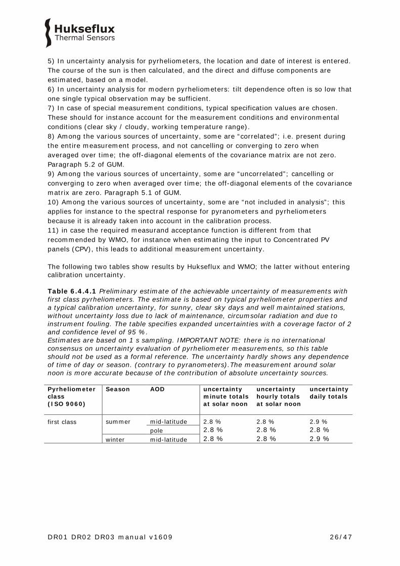
5) In uncertainty analysis for pyrheliometers, the location and date of interest is entered. The course of the sun is then calculated, and the direct and diffuse components are estimated, based on a model. 6) In uncertainty analysis for modern pyrheliometers: tilt dependence often is so low that one single typical observation may be sufficient. 7) In case of special measurement conditions, typical specification values are chosen. These should for instance account for the measurement conditions and environmental conditions (clear sky / cloudy, working temperature range). 8) Among the various sources of uncertainty, some are “correlated”; i.e. present during the entire measurement process, and not cancelling or converging to zero when averaged over time; the off-diagonal elements of the covariance matrix are not zero. Paragraph 5.2 of GUM. 9) Among the various sources of uncertainty, some are “uncorrelated”; cancelling or converging to zero when averaged over time; the off-diagonal elements of the covariance matrix are zero. Paragraph 5.1 of GUM. 10) Among the various sources of uncertainty, some are “not included in analysis”; this applies for instance to the spectral response for pyranometers and pyrheliometers because it is already taken into account in the calibration process. 11) in case the required measurand acceptance function is different from that recommended by WMO, for instance when estimating the input to Concentrated PV panels (CPV), this leads to additional measurement uncertainty. The following two tables show results by Hukseflux and WMO; the latter without entering calibration uncertainty. Table 6.4.4.1 Preliminary estimate of the achievable uncertainty of measurements with first class pyrheliometers. The estimate is based on typical pyrheliometer properties and a typical calibration uncertainty, for sunny, clear sky days and well maintained stations, without uncertainty loss due to lack of maintenance, circumsolar radiation and due to instrument fouling. The table specifies expanded uncertainties with a coverage factor of 2 and confidence level of 95 %. Estimates are based on 1 s sampling. IMPORTANT NOTE: there is no international consensus on uncertainty evaluation of pyrheliometer measurements, so this table should not be used as a formal reference. The uncertainty hardly shows any dependence of time of day or season. (contrary to pyranometers).The measurement around solar noon is more accurate because of the contribution of absolute uncertainty sources. Pyrheliometer class (ISO 9060)
Season AOD uncertainty minute totals at solar noon
uncertainty hourly totals at solar noon
uncertainty daily totals
first class
summer mid-latitude 2.8 % 2.8 % 2.9 % pole 2.8 % 2.8 % 2.8 % winter mid-latitude 2.8 % 2.8 % 2.9 %

DR01 DR02 DR03 manual v1609 27/47
Table 6.4.4.2 Estimate of achievable uncertainties of measurements with first class pyrheliometers according to WMO-No.-8, seventh edition, 2008. Copy from WMO Guide 7.2.1: The estimated uncertainties are based on the following assumptions: (a) Instruments are well-maintained, correctly aligned and clean; (b) 1 min and 1 h figures are for clear-sky irradiances at solar noon; (c) Daily exposure values are for clear days at mid-latitudes. IMPORTANT NOTE: According to 7.3.2.5 the achievable uncertainty does not include any calibration errors. IMPORTANT NOTE: Achievable accuracy is not part of the GUM vocabulary. Interval Achievable uncertainty Achievable uncertainty (95% confidence level) daily totals
± 1.0 %
Achievable uncertainty (95% confidence level) hourly totals
± 1.5 %
Achievable uncertainty (95% confidence level) minute totals
± 1.8 %
6.4.5 Calibration uncertainty Our latest calibration method results in an uncertainty of the sensitivity of less than 1.2 %. The user may receive an instrument with a lower uncertainty. See the calibration report for the exact value.

DR01 DR02 DR03 manual v1609 28/47
7 Maintenance and trouble shooting
7.1 Recommended maintenance and quality assurance
DR01 is typically used for high-accuracy measurements and cannot measure reliably at a low level of maintenance. As a general rule this means that regular cleaning of the window and visual inspection of alignment accuracy combined with a critical review of the measured data, preferably checking against other measurements, is the preferred way to obtain a reliable measurement. Table 7.1.1 Recommended maintenance of DR01. If possible the data analysis, tracker inspection and cleaning (1 and 2) should be done on a daily basis.
MINIMUM RECOMMENDED PYRHELIOMETER MAINTENANCE
INTERVAL SUBJECT ACTION
1 0.5 week cleaning use a soft cloth to clean the window of the instrument, persistent stains can be treated with soapy water or alcohol
tracking Inspect tracking and alignment, make adjustments if necessary
2 1 week data analysis compare measured data to maximum possible / maximum expected irradiance and to other measurements nearby (redundant instruments). Also historical seasonal records can be used as a source for expected values. Analyse night time signals. These may be slightly positive due to heating. Look for any patterns and events that deviate from what is normal or expected.
3 6 months inspection inspect cable quality, inspect cable glands, inspect mounting position, inspect cable, clean instrument, clean cable, inspect levelling, inspect mounting connection, inspect interior of window for condensation, inspect desiccant
4 2 years desiccant replacement
desiccant replacement
5 recalibration recalibration by side-by-side comparison to a higher standard instrument in the field according to ISO 9059
6 lifetime assessment
judge if the instrument should be reliable for another 2 years, or if it should be replaced
7 6 years parts replacement
if applicable / necessary replace the parts that are most exposed to weathering; cable, cable gland. NOTE: use Hukseflux approved parts only.
8 internal inspection
if applicable: open instrument and inspect / replace o-rings; dry internal cavity around the circuit board
DR01 DR02 DR03 manual v1609 29/47
7.2 Trouble shooting
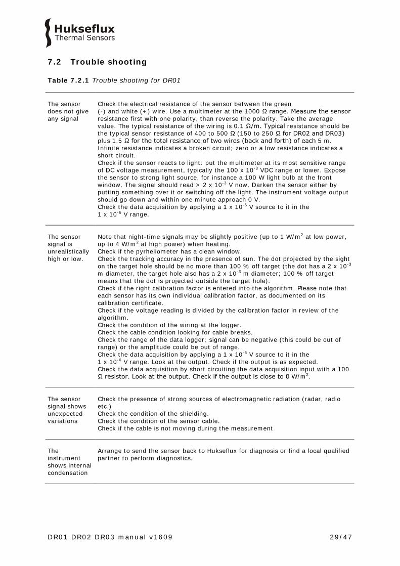
Table 7.2.1 Trouble shooting for DR01 The sensor does not give any signal
Check the electrical resistance of the sensor between the green (-) and white (+) wire. Use a multimeter at the 1000 Ω range. Measure the sensor resistance first with one polarity, than reverse the polarity. Take the average value. The typical resistance of the wiring is 0.1 Ω/m. Typical resistance should be the typical sensor resistance of 400 to 500 Ω (150 to 250 Ω for DR02 and DR03) plus 1.5 Ω for the total resistance of two wires (back and forth) of each 5 m. Infinite resistance indicates a broken circuit; zero or a low resistance indicates a short circuit. Check if the sensor reacts to light: put the multimeter at its most sensitive range of DC voltage measurement, typically the 100 x 10-3 VDC range or lower. Expose the sensor to strong light source, for instance a 100 W light bulb at the front window. The signal should read > 2 x 10⁻³ V now. Darken the sensor either by putting something over it or switching off the light. The instrument voltage output should go down and within one minute approach 0 V. Check the data acquisition by applying a 1 x 10⁻⁶ V source to it in the 1 x 10⁻⁶ V range.
The sensor signal is unrealistically high or low.
Note that night-time signals may be slightly positive (up to 1 W/m2 at low power, up to 4 W/m2 at high power) when heating. Check if the pyrheliometer has a clean window. Check the tracking accuracy in the presence of sun. The dot projected by the sight on the target hole should be no more than 100 % off target (the dot has a 2 x 10⁻³ m diameter, the target hole also has a 2 x 10⁻³ m diameter; 100 % off target means that the dot is projected outside the target hole). Check if the right calibration factor is entered into the algorithm. Please note that each sensor has its own individual calibration factor, as documented on its calibration certificate. Check if the voltage reading is divided by the calibration factor in review of the algorithm. Check the condition of the wiring at the logger. Check the cable condition looking for cable breaks. Check the range of the data logger; signal can be negative (this could be out of range) or the amplitude could be out of range. Check the data acquisition by applying a 1 x 10⁻⁶ V source to it in the 1 x 10⁻⁶ V range. Look at the output. Check if the output is as expected. Check the data acquisition by short circuiting the data acquisition input with a 100 Ω resistor. Look at the output. Check if the output is close to 0 W/m2.
The sensor signal shows unexpected variations
Check the presence of strong sources of electromagnetic radiation (radar, radio etc.) Check the condition of the shielding. Check the condition of the sensor cable. Check if the cable is not moving during the measurement
The instrument shows internal condensation
Arrange to send the sensor back to Hukseflux for diagnosis or find a local qualified partner to perform diagnostics.

DR01 DR02 DR03 manual v1609 30/47
7.3 Calibration and checks in the field
Recalibration of field pyrheliometers is typically done by comparison in the field to a reference pyrheliometer. The applicable standard is ISO 9059 “International Standard- Solar Energy- calibration of field pyrheliometers by comparison to a reference pyrheliometer”. At Hukseflux an indoor calibration according to the same standard is used. In case of field comparison; ISO allows use of sensors of the same class. Hukseflux recommends also using the same model, because an intercomparison of similar instruments has the advantage that they suffer from the same offsets and contributions of circumsolar radiation. ISO recommends to perform field calibration during several days; 2 to 3 days under cloudless conditions. In order to limit the influence of turbidity and aerosols Hukseflux suggests to using hourly totals near solar noon. Hukseflux main recommendations for field intercomparisons are: 1) to take high solar irradiance measurements at solar noon as a reference and not the entire day. 2) to take a reference of the same brand and type as the field pyrheliometer or a pyrheliometer of a higher class. 3) to connect both to the same electronics, so that electronics errors (also offsets) are eliminated. 4) to mount all instruments on the same platform, so that they have the same body temperature. 8) to correct deviations of more than ± 0.2 %. Lower deviations should be interpreted as acceptable and should not lead to a revised sensitivity.
7.4 Data quality assurance
Quality assurance can be done by: • analysing trends in solar irradiance signal • plotting the measured irradiance against mathematically generated expected values • comparing irradiance measurements between sites • analysis of night time signals The main idea is that one should look out for any unrealistic values. There are programs on the market that can automatically perform data screening: See http://www.dqms.com
DR01 DR02 DR03 manual v1609 31/47
8 DR03
8.1 Introduction DR03
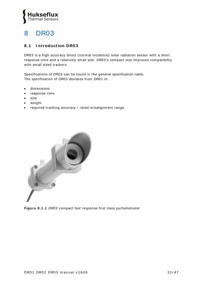
DR03 is a high accuracy direct (normal incidence) solar radiation sensor with a short response time and a relatively small size. DR03’s compact size improves compatibility with small sized trackers. Specifications of DR03 can be found in the general specification table. The specification of DR03 deviates from DR01 in: • dimensions • response time • size • weight • required tracking accuracy / rated misalignment range
Figure 8.1.1 DR03 compact fast response first class pyrheliometer

DR01 DR02 DR03 manual v1609 32/47
8.2 Dimensions of DR03
Figure 8.2.1 Overview of DR03: (1) humidity indicator (2) sights (3) aperture tube (4) protection cap (5) window assembly with heater (6) cable gland (7) cable (standard length 5 metres cable, optional longer cable)
Figure 8.2.2 Dimensions of DR03 in x 10-3 m
1
2
3
24
5
6
7
120
Ø 3
8
286
50

DR01 DR02 DR03 manual v1609 34/47
9 Appendices
9.1 Appendix on cable extension / replacement The standard sensor cable can be removed and installed by the user provided that the cable is sealed at the sensor side against humidity ingress. Please consult Hukseflux for instructions on cable preparation or use Hukseflux-supplied parts. DR01 is equipped with one cable. Keep the distance between data logger or amplifier and sensor as short as possible. Cables act as a source of distortion by picking up capacitive noise. In an electrically “quiet” environment the DR01 cable can however be extended without problem to 100 meters. If done properly, the sensor signal, although small, will not significantly degrade because the sensor resistance is very low (so good immunity to external sources) and because there is no current flowing (so no resistive losses). Cable and connection specifications are summarised below. NOTE: the body of DR01 contains connector blocks that can be used for the internal connection of a new cable. See the chapter on electrical connections. Usually it is easier to connect a new extended cable inside the pyrheliometer body cable than to make a good (weatherproof) connection to an existing cable. Table 9.1.1 Preferred specifications for cable extension of DR01 General
please consult Hukseflux for instructions or use Hukseflux-supplied parts.
Cable
8-wire, shielded, with copper conductors (at Hukseflux 8-wire shielded cable is used, of which 2 wires are used for signal transmission, 2 for heating and optionally 2 to 4 for the temperature sensor)
Sealing
sealed at the sensor side against humidity ingress
Core resistance
< 0.1 Ω/m
Outer diameter
± 2.5 to 6.5 x 10⁻³ m (to fit cable gland)
Length
cables should be kept as short as possible, in any case the total cable length should be less than 100 m
Outer sheet
specified for outdoor use (for good stability in outdoor applications)
Connection
either solder the new cable core and shield to the original sensor cable, and make a waterproof connection using cable shrink, or use gold plated waterproof connectors. Always connect shield.
DR01 DR02 DR03 manual v1609 35/47
9.2 Appendix on optional chassis connector & cable connector
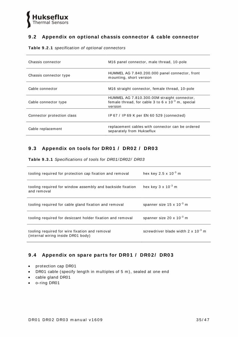
Table 9.2.1 specification of optional connectors
Chassis connector M16 panel connector, male thread, 10-pole
Chassis connector type HUMMEL AG 7.840.200.000 panel connector, front mounting, short version
Cable connector M16 straight connector, female thread, 10-pole
Cable connector type HUMMEL AG 7.810.300.00M straight connector, female thread, for cable 3 to 6 x 10⁻³ m, special version
Connector protection class IP 67 / IP 69 K per EN 60 529 (connected)
Cable replacement replacement cables with connector can be ordered separately from Hukseflux
9.3 Appendix on tools for DR01 / DR02 / DR03
Table 9.3.1 Specifications of tools for DR01/DR02/ DR03 tooling required for protection cap fixation and removal
hex key 2.5 x 10⁻³ m
tooling required for window assembly and backside fixation and removal
hex key 3 x 10⁻³ m
tooling required for cable gland fixation and removal
spanner size 15 x 10-3 m
tooling required for desiccant holder fixation and removal
spanner size 20 x 10-3 m
tooling required for wire fixation and removal (internal wiring inside DR01 body)
screwdriver blade width 2 x 10⁻³ m
9.4 Appendix on spare parts for DR01 / DR02/ DR03
• protection cap DR01 • DR01 cable (specify length in multiples of 5 m), sealed at one end • cable gland DR01 • o-ring DR01
DR01 DR02 DR03 manual v1609 36/47
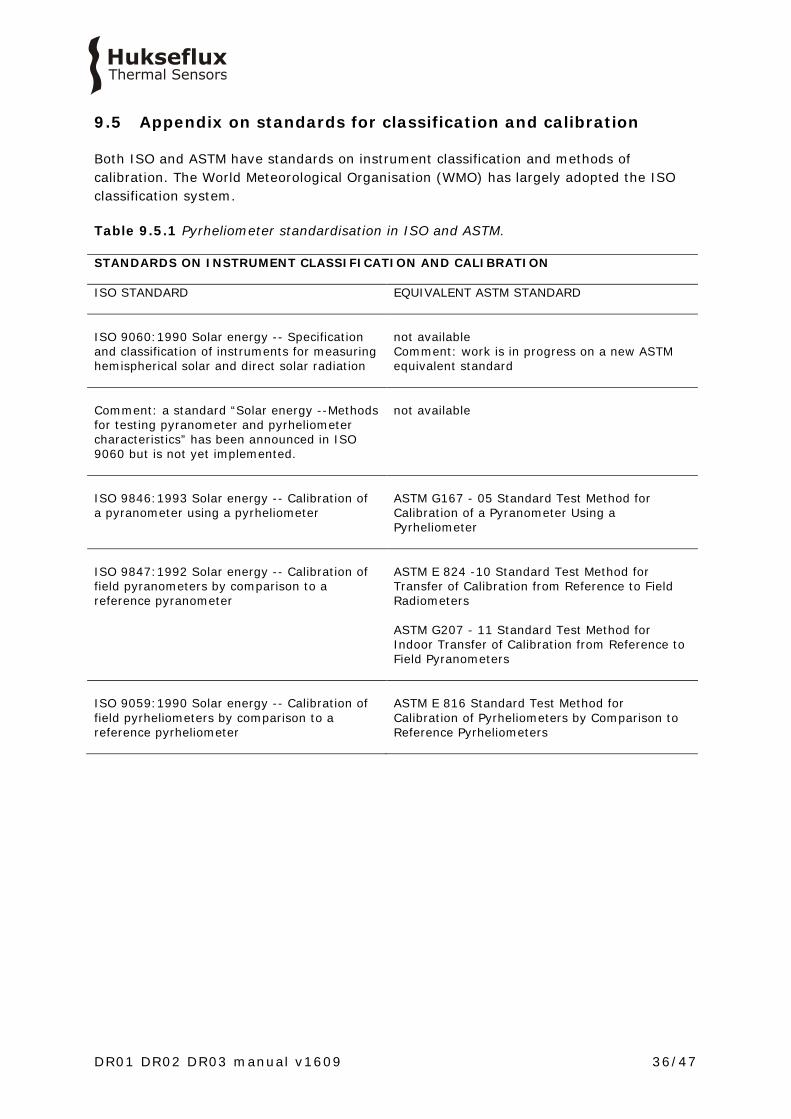
9.5 Appendix on standards for classification and calibration
Both ISO and ASTM have standards on instrument classification and methods of calibration. The World Meteorological Organisation (WMO) has largely adopted the ISO classification system. Table 9.5.1 Pyrheliometer standardisation in ISO and ASTM. STANDARDS ON INSTRUMENT CLASSIFICATION AND CALIBRATION ISO STANDARD
EQUIVALENT ASTM STANDARD
ISO 9060:1990 Solar energy -- Specification and classification of instruments for measuring hemispherical solar and direct solar radiation
not available Comment: work is in progress on a new ASTM equivalent standard
Comment: a standard “Solar energy --Methods for testing pyranometer and pyrheliometer characteristics” has been announced in ISO 9060 but is not yet implemented.
not available
ISO 9846:1993 Solar energy -- Calibration of a pyranometer using a pyrheliometer
ASTM G167 - 05 Standard Test Method for Calibration of a Pyranometer Using a Pyrheliometer
ISO 9847:1992 Solar energy -- Calibration of field pyranometers by comparison to a reference pyranometer
ASTM E 824 -10 Standard Test Method for Transfer of Calibration from Reference to Field Radiometers ASTM G207 - 11 Standard Test Method for Indoor Transfer of Calibration from Reference to Field Pyranometers
ISO 9059:1990 Solar energy -- Calibration of field pyrheliometers by comparison to a reference pyrheliometer
ASTM E 816 Standard Test Method for Calibration of Pyrheliometers by Comparison to Reference Pyrheliometers
DR01 DR02 DR03 manual v1609 37/47
9.6 Appendix on calibration hierarchy
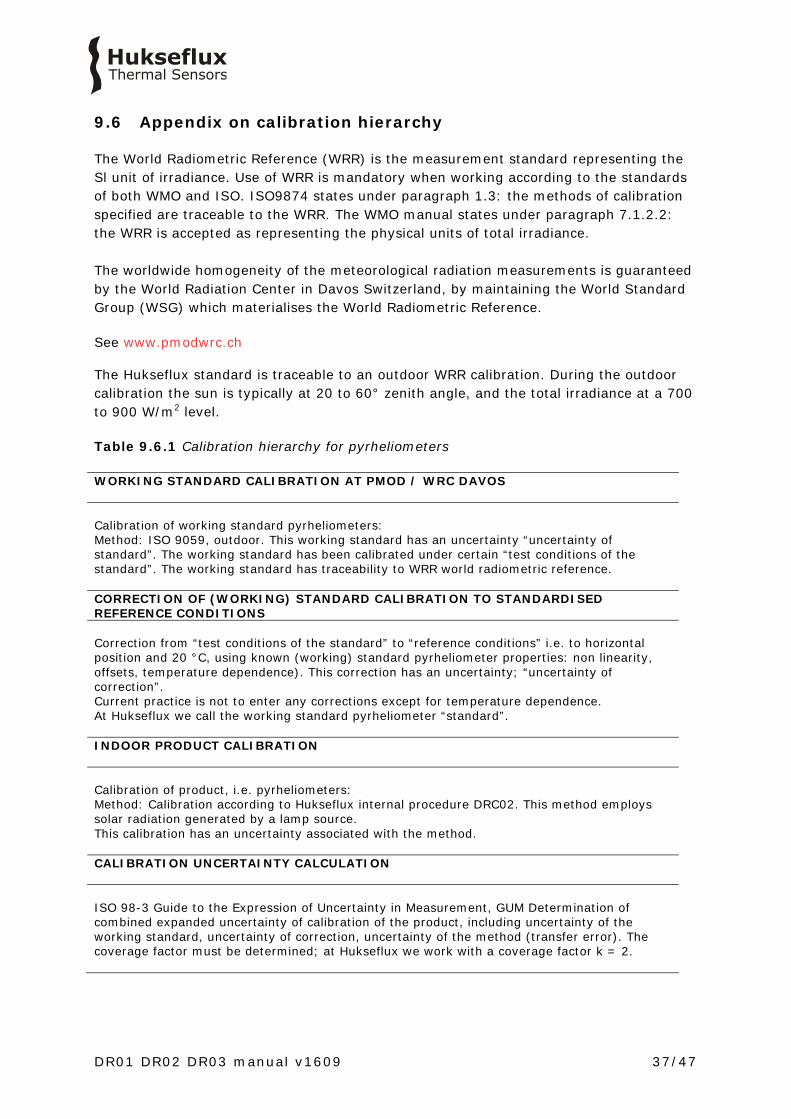
The World Radiometric Reference (WRR) is the measurement standard representing the Sl unit of irradiance. Use of WRR is mandatory when working according to the standards of both WMO and ISO. ISO9874 states under paragraph 1.3: the methods of calibration specified are traceable to the WRR. The WMO manual states under paragraph 7.1.2.2: the WRR is accepted as representing the physical units of total irradiance. The worldwide homogeneity of the meteorological radiation measurements is guaranteed by the World Radiation Center in Davos Switzerland, by maintaining the World Standard Group (WSG) which materialises the World Radiometric Reference. See www.pmodwrc.ch The Hukseflux standard is traceable to an outdoor WRR calibration. During the outdoor calibration the sun is typically at 20 to 60° zenith angle, and the total irradiance at a 700 to 900 W/m2 level. Table 9.6.1 Calibration hierarchy for pyrheliometers WORKING STANDARD CALIBRATION AT PMOD / WRC DAVOS Calibration of working standard pyrheliometers: Method: ISO 9059, outdoor. This working standard has an uncertainty “uncertainty of standard”. The working standard has been calibrated under certain “test conditions of the standard”. The working standard has traceability to WRR world radiometric reference. CORRECTION OF (WORKING) STANDARD CALIBRATION TO STANDARDISED REFERENCE CONDITIONS Correction from “test conditions of the standard” to “reference conditions” i.e. to horizontal position and 20 °C, using known (working) standard pyrheliometer properties: non linearity, offsets, temperature dependence). This correction has an uncertainty; “uncertainty of correction”. Current practice is not to enter any corrections except for temperature dependence. At Hukseflux we call the working standard pyrheliometer “standard”. INDOOR PRODUCT CALIBRATION Calibration of product, i.e. pyrheliometers: Method: Calibration according to Hukseflux internal procedure DRC02. This method employs solar radiation generated by a lamp source. This calibration has an uncertainty associated with the method. CALIBRATION UNCERTAINTY CALCULATION ISO 98-3 Guide to the Expression of Uncertainty in Measurement, GUM Determination of combined expanded uncertainty of calibration of the product, including uncertainty of the working standard, uncertainty of correction, uncertainty of the method (transfer error). The coverage factor must be determined; at Hukseflux we work with a coverage factor k = 2.

DR01 DR02 DR03 manual v1609 38/47
9.7 Appendix on requirements for solar tracking
For a correct measurement the DR01 should be pointed at the sun. It usually mounted on a solar tracker.Theoretically the alignment accuracy of a pyrheliometer should be better than the slope angle minus the full angle of the solar disk, i.e within 0.5 °. However, in practice a wider misalignment interval may be tolerated. ISO 9059-1990 paragraph 5.3.2 specifies that a misalignment of the slope angle minus 0.25 ° is permitted. With Hukseflux pyrheliometers that would allow 0.75 ° pointing error, which is rounded off to < 0.7 °. An independent simulation in the BSRN operations manual figure 4.7 indicates that a pointing error of < 0.7 ° does not lead to significant measurement errors. During production, the optical axis of the pyrheliometer is aligned with its sights. In outdoor operation the tracker is on its turn aligned along the zenith axis with its own level, and in the azimuth direction with the pyrheliometer sights. The latter is typically done using the sun as a source. The resolution (i.e. the ability to meaningfully distinguish between measurement results) of the DR01 and DR02 sights is 0.2 °. This means that if the pyrheliometer sight is used as a reference, the tracking accuracy should remain within 0.6 °. Hukseflux therefore specifies a rated misalignment interval (i.e. without impact on pyrheliometer measurement accuracy) of ± 0.5 ° from the sun centre using the pyrheliometer sight as a reference. The sight resolution of DR03 is 0.4 ° so the rated misalignment interval for DR03 is ± 0.3 ° from the sun centre using the pyrheliometer sight as a reference. Some trackers employ active control with a sun sensor: The BSRN operations manual in 2.2.1.1 recommends a tracker with a 4-quadrant sun sensor. The tracker accuracy is recommended to be < 0.1 °. However, this is not a requirement for pyrheliometers, which can operate with a 0.75 ° pointing error or a 0.5 ° detectable misalignment. Verbal communication with the editor of the BSRN manual, B. Forgan, in October 2015 confirmed that the specified tracking accuracy is a requirement for operation of sun photometers. The BSRN manual will be adapted to correct this mistake. In case a sun sensor is used, this sensor typically controls tracking as soon as the direct solar irradiance is above a certain level. In that case the pyrheliometers should be aligned with the sun sensor, and the rated solar tracking range, defined for passive tracking based on calculation, may be relaxed. In case we use a sun sensor with < 0.1 ° misalignment, this is much better than required for pyrheliometers. Please note that sun sensors must be regularly cleaned to be dependable. The 4-quadrant type sun sensor also needs regular recalibration to make sure that the individual drift of the 4 quadrants is compensated for.

DR01 DR02 DR03 manual v1609 39/47
9.8 Appendix on meteorological radiation quantities
A pyrheliometer measures irradiance. The time integrated total is called radiant exposure. In solar energy radiant exposure is often given in W∙h/m2. Table 9.8.1 Meteorological radiation quantities as recommended by WMO (additional symbols by Hukseflux Thermal Sensor). POA stands for Plane of Array irradiance. The term originates from ASTM and IEC standards. SYMBOL DESCRIPTION CALCULATION UNITS ALTERNATIVE
EXPRESSION E↓ downward irradiance E↓ = Eg ↓ + El↓ W/m2
H↓ downward radiant exposure for a specified time interval
H↓ = Hg↓ + Hl ↓ J/m2 W∙h/m2 Change of units
E↑ upward irradiance E↑ = Eg ↑ + El ↑ W/m2
H↑ upward radiant exposure for a specified time interval
H↑ = Hg ↑ + Hl ↑ J/m2 W∙h/m2 Change of units
E direct solar irradiance normal to the apparent solar zenith angle
W/m2 DNI Direct Normal Irradiance
E0 solar constant W/m2
Eg ↓ h global irradiance; hemispherical irradiance on a specified, in this case horizontal surface.*
Eg↓ = E cos θh + Ed↓ W/m2 GHI Global Horizontal Irradiance
Eg ↓ t global irradiance; hemispherical irradiance on a specified, in this case tilted surface.*
Eg ↓ = E∙cos θt + Ed ↓ t + Er↑ t ***
W/m2 POA Plane of Array
Ed ↓ downward diffuse solar radiation
W/m2 DHI Diffuse Horizontal Irradiance
El ↑, El ↓ upward / downward long-wave irradiance
W/m2
Er↑ reflected solar irradiance W/m2
E* net irradiance E* = E↓ – E↑ W/m2
T↓ apparent surface
temperature** º C or K
T↑ apparent sky temperature**
º C or K
SD sunshine duration h θ is the apparent solar zenith angle θh relative to horizontal, θt relative to a tilted surface g = global, l = long wave, t = tilted *, h = horizontal* * distinction horizontal and tilted by Hukseflux, ** T symbols introduced by Hukseflux, *** contributions of Ed ↓ t and Er↑ t are Ed ↓ and Er↑ both corrected for the tilt angle of the surface
DR01 DR02 DR03 manual v1609 40/47
9.9 Appendix on ISO and WMO classification tables
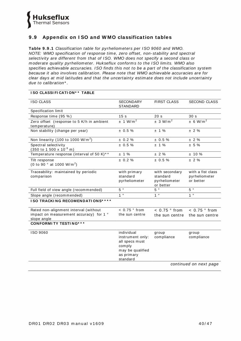
Table 9.9.1 Classification table for pyrheliometers per ISO 9060 and WMO. NOTE: WMO specification of response time, zero offset, non-stability and spectral selectivity are different from that of ISO. WMO does not specify a second class or moderate quality pyrheliometer. Hukseflux conforms to the ISO limits. WMO also specifies achievable accuracies. ISO finds this not to be a part of the classification system because it also involves calibration. Please note that WMO achievable accuracies are for clear days at mid latitudes and that the uncertainty estimate does not include uncertainty due to calibration*. ISO CLASSIFICATION** TABLE ISO CLASS SECONDARY
STANDARD FIRST CLASS SECOND CLASS
Specification limit Response time (95 %) 15 s 20 s 30 s Zero offset (response to 5 K/h in ambient temperature)
± 1 W/m2 ± 3 W/m2 ± 6 W/m2
Non stability (change per year) ± 0.5 % ± 1 %
± 2 %
Non linearity (100 to 1000 W/m2) ± 0.2 % ± 0.5 % ± 2 % Spectral selectivity (350 to 1 500 x 10-9 m)
± 0.5 % ± 1 % ± 5 %
Temperature response (interval of 50 K)** ± 1 % ± 2 % ± 10 % Tilt response (0 to 90 ° at 1000 W/m2)
± 0.2 % ± 0.5 % ± 2 %
Traceability: maintained by periodic comparison
with primary standard pyrheliometer
with secondary standard pyrheliometer or better
with a fist class pyrheliometer or better
Full field of view angle (recommended) 5 ° 5 ° 5 ° Slope angle (recommended) 1 ° 1 ° 1 ° ISO TRACKING RECOMENDATIONS****
Rated non-alignment interval (without impact on measurement accuracy) for 1 ° slope angle
< 0.75 ° from the sun centre
< 0.75 ° from the sun centre
< 0.75 ° from the sun centre
CONFORMITY TESTING***
ISO 9060 individual instrument only: all specs must comply may be qualified as primary standard
group compliance
group compliance
continued on next page

DR01 DR02 DR03 manual v1609 41/47
started on previous page ADDITIONAL WMO SPECIFICATIONS (DEVIATING FROM ISO 9060) WMO CLASS HIGH QUALITY GOOD
QUALITY MODERATE QUALITY
WMO: response time (95 %) 15 s 30 s WMO: spectral selectivity (300 to 3 000 x 10-9 m)
± 0.5 % ± 1 % Not applicable
WMO: zero offset (response to 5 K/h in ambient temperature)
± 2 W/m2 ± 4 W/m2 Not applicable
WMO: non stability (change per year) ± 0.1 % ± 0.5 % Not applicable WMO: achievable accuracy for daily sums* ± 0.5 % ± 1.0 % Not applicable WMO: achievable accuracy for hourly sums* ± 0.7 % ± 1.5 % Not applicable WMO: achievable accuracy for minute sums* ± 0.9 % ± 1.8 % Not applicable WMO: resolution (smallest detectable change)
± 0.51 W/m2 ± 1 W/m2 Not applicable
* WMO 7.2.1: The estimated uncertainties are based on the following assumptions: (a) instruments are well-maintained, correctly aligned and clean; (b) 1 min and 1 h figures are for clear-sky irradiances at solar noon; (c) daily exposure values are for clear days at mid-latitudes. WMO 7.3.2.5: Table 7.5 lists the expected maximum deviation from the true value, excluding calibration errors. ** At Hukseflux we use the expression ± 1 % instead of a range of 2 %. *** an instrument is subject to conformity testing of its specifications. Depending on the classification, conformity compliance can be proven either by group- or individual compliance. A specification is fulfilled if the mean value of the respective test result does not exceed the corresponding limiting value of the specification for the specific category of instrument. **** ISO 9059 Solar energy - Calibration of field pyrheliometers by comparison to a reference pyrheliometer paragraph 5.3.2 allows slope angle minus 0.25 °, which is rounded off to 0.7 °. See also paragraph 2.1 on requirements for tracking.
DR01 DR02 DR03 manual v1609 42/47
9.10 Appendix on definition of pyrheliometer specifications
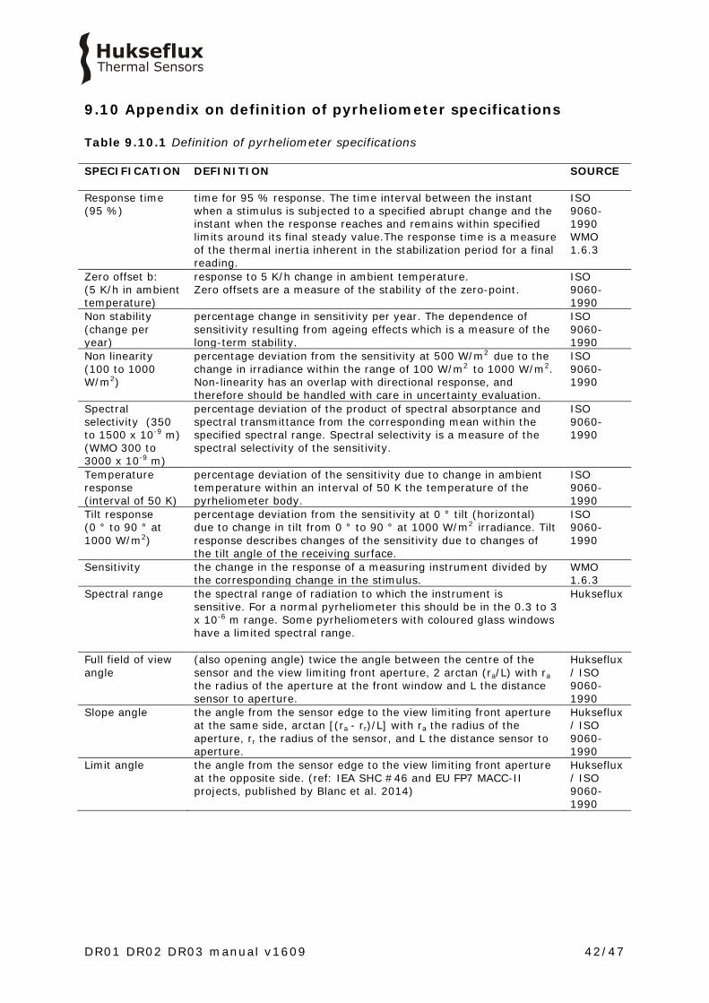
Table 9.10.1 Definition of pyrheliometer specifications SPECIFICATION DEFINITION SOURCE
Response time (95 %)
time for 95 % response. The time interval between the instant when a stimulus is subjected to a specified abrupt change and the instant when the response reaches and remains within specified limits around its final steady value.The response time is a measure of the thermal inertia inherent in the stabilization period for a final reading.
ISO 9060-1990 WMO 1.6.3
Zero offset b: (5 K/h in ambient temperature)
response to 5 K/h change in ambient temperature. Zero offsets are a measure of the stability of the zero-point.
ISO 9060-1990
Non stability (change per year)
percentage change in sensitivity per year. The dependence of sensitivity resulting from ageing effects which is a measure of the long-term stability.
ISO 9060-1990
Non linearity (100 to 1000 W/m2)
percentage deviation from the sensitivity at 500 W/m2 due to the change in irradiance within the range of 100 W/m2 to 1000 W/m2. Non-linearity has an overlap with directional response, and therefore should be handled with care in uncertainty evaluation.
ISO 9060-1990
Spectral selectivity (350 to 1500 x 10-9 m) (WMO 300 to 3000 x 10-9 m)
percentage deviation of the product of spectral absorptance and spectral transmittance from the corresponding mean within the specified spectral range. Spectral selectivity is a measure of the spectral selectivity of the sensitivity.
ISO 9060-1990
Temperature response (interval of 50 K)
percentage deviation of the sensitivity due to change in ambient temperature within an interval of 50 K the temperature of the pyrheliometer body.
ISO 9060-1990
Tilt response (0 ° to 90 ° at 1000 W/m2)
percentage deviation from the sensitivity at 0 ° tilt (horizontal) due to change in tilt from 0 ° to 90 ° at 1000 W/m2 irradiance. Tilt response describes changes of the sensitivity due to changes of the tilt angle of the receiving surface.
ISO 9060-1990
Sensitivity the change in the response of a measuring instrument divided by the corresponding change in the stimulus.
WMO 1.6.3
Spectral range the spectral range of radiation to which the instrument is sensitive. For a normal pyrheliometer this should be in the 0.3 to 3 x 10⁻⁶ m range. Some pyrheliometers with coloured glass windows have a limited spectral range.
Hukseflux
Full field of view angle
(also opening angle) twice the angle between the centre of the sensor and the view limiting front aperture, 2 arctan (ra/L) with ra the radius of the aperture at the front window and L the distance sensor to aperture.
Hukseflux / ISO 9060-1990
Slope angle the angle from the sensor edge to the view limiting front aperture at the same side, arctan [(ra - rr)/L] with ra the radius of the aperture, rr the radius of the sensor, and L the distance sensor to aperture.
Hukseflux / ISO 9060-1990
Limit angle the angle from the sensor edge to the view limiting front aperture at the opposite side. (ref: IEA SHC #46 and EU FP7 MACC-II projects, published by Blanc et al. 2014)
Hukseflux / ISO 9060-1990
DR01 DR02 DR03 manual v1609 43/47
9.11 Appendix on terminology / glossary
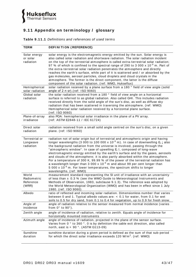
Table 9.11.1 Definitions and references of used terms TERM DEFINITION (REFERENCE)
Solar energy or solar radiation
solar energy is the electromagnetic energy emitted by the sun. Solar energy is also called solar radiation and shortwave radiation. The solar radiation incident on the top of the terrestrial atmosphere is called extra-terrestrial solar radiation; 97 % of which is confined to the spectral range of 290 to 3 000 x 10-9 m. Part of the extra-terrestrial solar radiation penetrates the atmosphere and directly reaches the earth’s surface, while part of it is scattered and / or absorbed by the gas molecules, aerosol particles, cloud droplets and cloud crystals in the atmosphere. The former is the direct component, the latter is the diffuse component of the solar radiation. (ref: WMO, Hukseflux)
Hemispherical solar radiation
solar radiation received by a plane surface from a 180 ° field of view angle (solid angle of 2 π sr).(ref: ISO 9060)
Global solar radiation
the solar radiation received from a 180 ° field of view angle on a horizontal surface is referred to as global radiation. Also called GHI. This includes radiation received directly from the solid angle of the sun’s disc, as well as diffuse sky radiation that has been scattered in traversing the atmosphere. (ref: WMO) Hemispherical solar radiation received by a horizontal plane surface. (ref: ISO 9060)
Plane-of-array irradiance
also POA: hemispherical solar irradiance in the plane of a PV array. (ref: ASTM E2848-11 / IEC 61724)
Direct solar radiation
radiation received from a small solid angle centred on the sun’s disc, on a given plane. (ref: ISO 9060)
Terrestrial or Longwave radiation
radiation not of solar origin but of terrestrial and atmospheric origin and having longer wavelengths (3 000 to 100 000 x 10-9 m). In case of downwelling El ↓ also the background radiation from the universe is involved, passing through the ”atmospheric window”. In case of upwelling El ↑, composed of long-wave electromagnetic energy emitted by the earth’s surface and by the gases, aerosols and clouds of the atmosphere; it is also partly absorbed within the atmosphere. For a temperature of 300 K, 99.99 % of the power of the terrestrial radiation has a wavelength longer than 3 000 x 10-9 m and about 99 per cent longer than 5 000 x 10-9 m. For lower temperatures, the spectrum shifts to longer wavelengths. (ref: WMO)
World Radiometric Reference (WRR)
measurement standard representing the Sl unit of irradiance with an uncertainty of less than ± 0.3 % (see the WMO Guide to Meteorological Instruments and Methods of Observation, 1983, subclause 9.1.3). The reference was adopted by the World Meteorological Organization (WMO) and has been in effect since 1 July 1980. (ref: ISO 9060)
Albedo ratio of reflected and incoming solar radiation. Dimensionless number that varies between 0 and 1. Typical albedo values are: < 0.1 for water, from 0.1 for wet soils to 0.5 for dry sand, from 0.1 to 0.4 for vegetation, up to 0.9 for fresh snow.
Angle of incidence
angle of radiation relative to the sensor measured from normal incidence (varies from 0° to 90°).
Zenith angle angle of incidence of radiation, relative to zenith. Equals angle of incidence for horizontally mounted instruments
Azimuth angle angle of incidence of radiation, projected in the plane of the sensor surface. Varies from 0 ° to 360 °. 0 is by definition the cable exit direction, also called north, east is + 90 °. (ASTM G113-09)
Sunshine duration
sunshine duration during a given period is defined as the sum of that sub-period for which the direct solar irradiance exceeds 120 W/m2. (ref: WMO)

DR01 DR02 DR03 manual v1609 44/47
The IEA SHC #46 and EU FP7 MACC-II projects (Blanc et al. 2014) concluded that the ISO and WMO definitions are insufficiently clear and suggest the following new and refined definitions: Table 9.11.2 Proposed new and not yet formally accepted pyrheliometer-related definitions as suggested by IEA SHC #46 and EU FP7 MACC-II projects, published by Blanc et al. 2014, compared to ISO and WMO TERM PROPOSED NEW DEFINITION (REFERENCE)
Pyrheliometer radiometer designed for measuring the irradiance which results from the solar
radiant flux from a well-defined solid angle the axis of which is perpendicular to the plane receiver surface. (ref: WMO)
Pyrheliometer a radiometer designed to measure DNI (i.e. including some circumsolar irradiance). Recommended parameters for the view-limiting geometry are a full opening angle of 5 °, and a slope angle of 1 °, and therefore a limit angle of 4 °. (ref: IEA SHC #46 and EU FP7 MACC-II projects, published by Blanc et al. 2014)
Direct solar radiation
DNI, the solar radiant flux collected by a plane unit surface normal to the axis pointing towards the centre of the Sun, within an optical angular aperture. This aperture is characterized by an acceptance function. (ref: IEA SHC #46 and EU FP7 MACC-II projects, published by Blanc et al. 2014)
Direct solar radiation
radiation received from a small solid angle centred on the sun’s disc, on a given plane. (ref: ISO 9060)
Direct solar radiation from the Sun
DNI from the Sun, the solar radiant flux collected by a plane unit surface normal to the axis pointing towards centre of the Sun, within the extent of the solar disk only (half-angle S = 0.266 ° ± 1.7 %), with a perfect radially symmetric rectangular acceptance function. (ref: IEA SHC #46 and EU FP7 MACC-II projects, published by Blanc et al. 2014)
Acceptance function
the acceptance function of an optical angular aperture: the fraction of the total radiant flux that is collected by an optical angular aperture, as a function of the off-axis angles. The geometrically perfect acceptance function is equal to one up to the slope angle, and equals zero for off-axis angles larger than the limit angle. (ref: IEA SHC #46 and EU FP7 MACC-II projects, published by Blanc et al. 2014)
Pyrheliometer acceptance function
The acceptance function of a pyrheliometer: the fraction of the total radiant flux that is collected by the combination of sensor and optical angular aperture, as a function of the off-axis angles. (ref: IEA SHC #46 and EU FP7 MACC-II projects, published by Blanc et al. 2014)
Opening angle (also full field of view angle): twice the angle between the centre of the sensor and the view limiting front aperture. (ref: IEA SHC #46 and EU FP7 MACC-II projects, published by Blanc et al. 2014)
Limit angle the angle from the sensor edge to the view limiting front aperture at the opposite side. (ref: IEA SHC #46 and EU FP7 MACC-II projects, published by Blanc et al. 2014)
Slope angle the angle from the sensor edge to the view limiting front aperture at the same side. (ref: IEA SHC #46 and EU FP7 MACC-II projects, published by Blanc et al. 2014)

DR01 DR02 DR03 manual v1609 45/47
9.12 Appendix on literature references
1. Blanc et al. (2014) Direct normal irradiance related definitions and applications; the circumsolar issue, Solar Energy, Volume December 2014, pp. 561-577 2. ISO (1990), ISO 9060-Solar energy - Specification and classification of instruments for measuring hemispherical solar and direct solar radiation, first edition 3. ISO / IEC (1995), GUIDE 98-3 Uncertainty of measurement — Part 3: Guide to the expression of uncertainty in measurement (GUM:1995), also published as JCGM 100:2008, published on internet, accessed 15-JAN-2014 4. JCGM (2008), JCGM 200:2008 International vocabulary of metrology — Basic and general concepts and associated terms (VIM), published on internet, accessed 15-JAN-2014

DR01 DR02 DR03 manual v1609 46/47
9.13 EC declaration of conformity
We, Hukseflux Thermal Sensors B.V. Delftechpark 31 2628 XJ Delft The Netherlands in accordance with the requirements of the following directive: 2004/108/EC The Electromagnetic Compatibility Directive hereby declare under our sole responsibility that: Product model: DR01, DR02, DR03 Product type: Pyrheliometer has been designed to comply and is in conformity with the relevant sections and applicable requirements of the following standards: Emission: EN 61326-1 (2006) Immunity: EN 61326-1 (2006) Emission: EN 61000-3-2 (2006) Emission: EN 61000-3-3 (1995) + A1 (2001) + A2 (2005) Report: 08C01340RPT01, 06 January 2009
Eric HOEKSEMA Director Delft January 15, 2014

© 2016, Hukseflux Thermal Sensors B.V. www.hukseflux.com
Hukseflux Thermal Sensors B.V. reserves the right to change specifications without notice.


![GPH12DU Chassis - Encompass Be sure no power is applied to the chassis or circuit, and observe all other safety precautions. 8. ... This TV supports [HDAVI Control 4] function. PC](https://static.fdocument.org/doc/165x107/5adb28017f8b9a6d7e8d9e5b/gph12du-chassis-encompass-sure-no-power-is-applied-to-the-chassis-or-circuit.jpg)