US Vision of Space Exploration -...
41
US Vision of Space US Vision of Space Exploration Exploration : : LRO as a 1 LRO as a 1 st st step step Dr. Jim Garvin Dr. Jim Garvin Chief Scientist Chief Scientist ILC 2005, Toronto, Canada ILC 2005, Toronto, Canada Sept. 19, 2005 Sept. 19, 2005
Transcript of US Vision of Space Exploration -...
US Vision of Space US Vision of Space ExplorationExploration: : LRO as a 1LRO as a 1stst stepstep
Dr. Jim GarvinDr. Jim GarvinChief ScientistChief Scientist
ILC 2005, Toronto, CanadaILC 2005, Toronto, Canada
Sept. 19, 2005Sept. 19, 2005
From a New Earth to a New Moon…
Earth MOON: S. Polar Region (Arecibo-Greenbank SARCourtesy D. Campbell, B. Campbell et al (2005)
ILC2005, Toronto
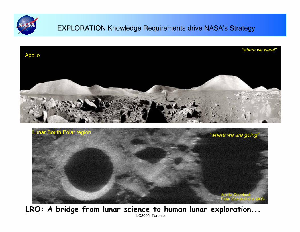
EXPLORATION Knowledge Requirements drive NASA’s Strategy
Apollo
LRO: A bridge from lunar science to human lunar exploration...
Lunar South Polar region
Arecibo-GreenbankRadar (Campbell et al. 2005)
“where we were!”
“where we are going”
11/1/2005 ILC2005 (Toronto)
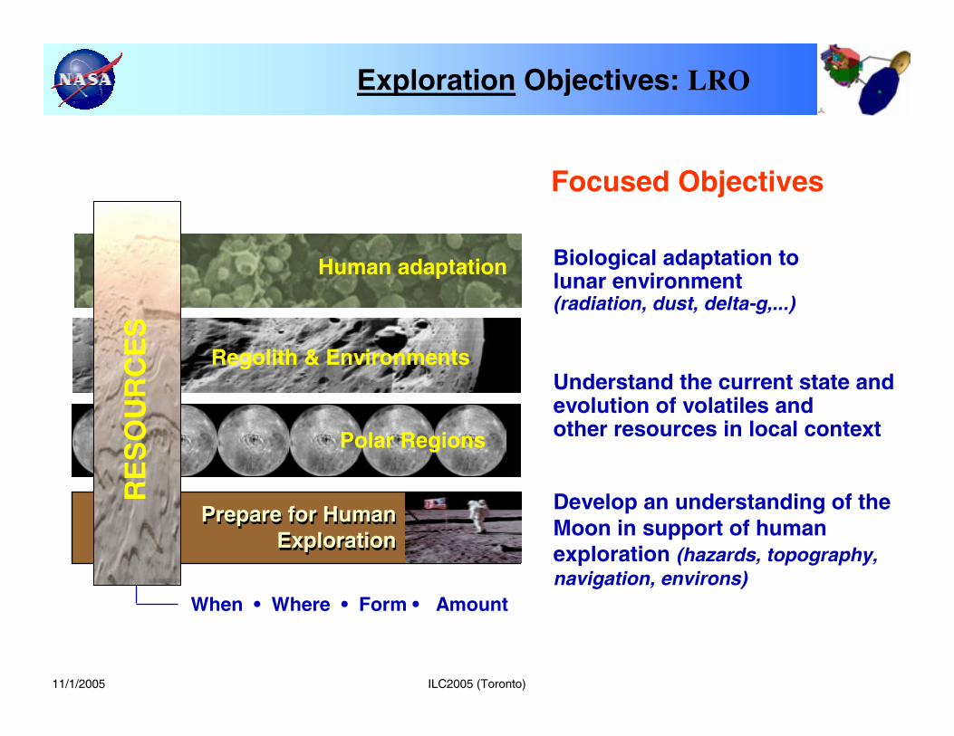
Develop an understanding of the Moon in support of human exploration (hazards, topography, navigation, environs)
Biological adaptation to lunar environment (radiation, dust, delta-g,...)
Understand the current state and evolution of volatiles andother resources in local context
Focused Objectives
GEOLOGYGEOLOGY
EnvironsEnvirons
Prepare for Human Exploration
Prepare for Human Exploration
When • Where • Form • Amount
Regolith & Environments
Polar Regions
Human adaptation
RE
SO
UR
CE
S
Exploration Objectives: LRO
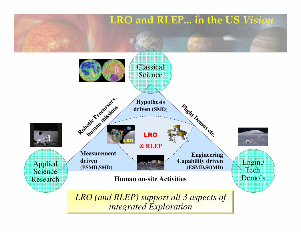
LRO and RLEP... in the US Vision
Classical Science
Applied Science
Research
Engin./Tech.
Demo’s
LRO (and RLEP) support all 3 aspects of integrated Exploration
LRO
& RLEP
Hypothesis driven (SMD)
Robot
ic Pre
curs
ors,
human
miss
ions Flight Demos etc.
Measurement driven (ESMD,SMD)
Engineering Capability driven
(ESMD,SOMD)
Human on-site Activities
LRO
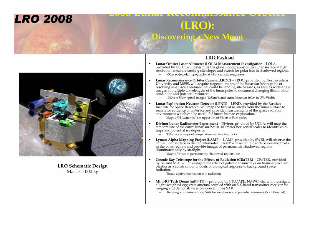
2008 Lunar Reconnaissance Orbiter (LRO):
Discovering a New Moon
LRO Payload• Lunar Orbiter Laser Altimeter (LOLA) Measurement Investigation – LOLA,
provided by GSFC, will determine the global topography of the lunar surface at high resolution, measure landing site slopes and search for polar ices in shadowed regions.
– ~50m scale polar topography at <1m vertical, roughness
• Lunar Reconnaissance Orbiter Camera (LROC) – LROC, provided by Northwestern University and MSSS, will acquire targeted images of the lunar surface capable of resolving small-scale features that could be landing site hazards, as well as wide-angle images at multiple wavelengths of the lunar poles to document changing illumination conditions and potential resources.
– 1000’s of 50cm/pixel images (125km2), and entire Moon at 100m in UV, Visible
• Lunar Exploration Neutron Detector (LEND) – LEND, provided by the Russian Institute for Space Research, will map the flux of neutrons from the lunar surface to search for evidence of water ice and provide measurements of the space radiation environment which can be useful for future human exploration.
– Maps of H (water ice?) in upper 1m of Moon at 5km scales
• Diviner Lunar Radiometer Experiment – Diviner, provided by UCLA, will map the temperature of the entire lunar surface at 300 meter horizontal scales to identify cold-traps and potential ice deposits.
– 300 m scale maps of temperature, surface ice, rocks
• Lyman-Alpha Mapping Project (LAMP) – LAMP, provided by SWRI, will observe the entire lunar surface in the far ultraviolet. LAMP will search for surface ices and frosts in the polar regions and provide images of permanently shadowed regions illuminated only by starlight.
– Maps of frosts in permanently shadowed regions, etc.
• Cosmic Ray Telescope for the Effects of Radiation (CRaTER) – CRaTER, provided by BU and MIT, will investigate the effect of galactic cosmic rays on tissue-equivalent plastics as a constraint on models of biological response to background space radiation.
– Tissue equivalent response to radiation
• Mini-RF Tech Demo (mRF-TD) – provided by JHU/APL, NAWC, etc. will investigate a light-weighted egg-crate antenna coupled with an S,X-band transmitter-receiver for ranging and demonstrate a low-power, mass SAR.
– Ranging, communications, SAR for roughness and potential resources (50-150m/pxl)
LRO Schematic DesignMass ~ 1000 kg
LRO 2008
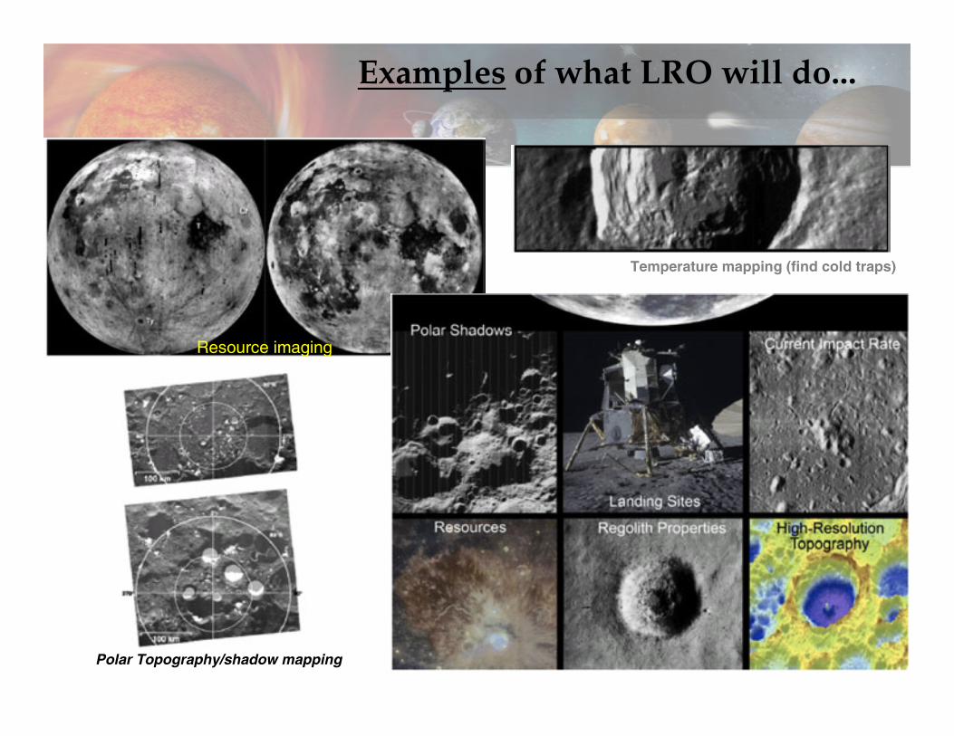
Examples of what LRO will do...
Polar Topography/shadow mapping
Resource imaging
Temperature mapping (find cold traps)
11/1/2005
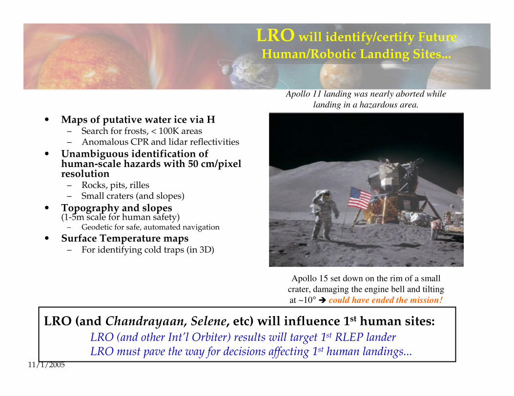
LRO will identify/certify Future Human/Robotic Landing Sites...
• Maps of putative water ice via H– Search for frosts, < 100K areas– Anomalous CPR and lidar reflectivities
• Unambiguous identification of human-scale hazards with 50 cm/pixel resolution
– Rocks, pits, rilles– Small craters (and slopes)
• Topography and slopes(1-5m scale for human safety)
– Geodetic for safe, automated navigation
• Surface Temperature maps– For identifying cold traps (in 3D)
LRO (and Chandrayaan, Selene, etc) will influence 1st human sites:LRO (and other Int’l Orbiter) results will target 1st RLEP landerLRO must pave the way for decisions affecting 1st human landings...
Apollo 15 set down on the rim of a smallcrater, damaging the engine bell and tiltingat ~10° could have ended the mission!
Apollo 11 landing was nearly aborted while landing in a hazardous area.
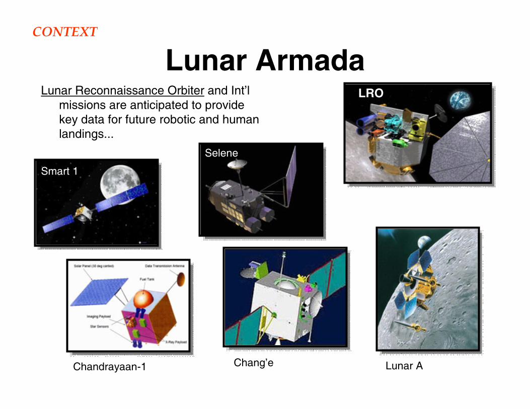
Lunar ArmadaLunar Reconnaissance Orbiter and Int’l
missions are anticipated to provide key data for future robotic and human landings...
Chandrayaan-1
Smart 1
LRO
Selene
Chang’e Lunar A
CONTEXT
ILC2005, Toronto
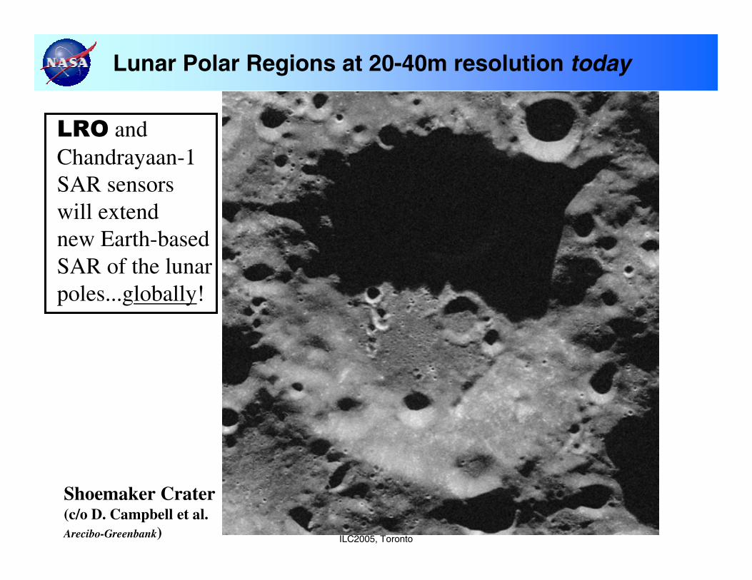
Lunar Polar Regions at 20-40m resolution today
LRO andChandrayaan-1SAR sensorswill extendnew Earth-basedSAR of the lunarpoles...globally!
Shoemaker Crater(c/o D. Campbell et al.Arecibo-Greenbank)
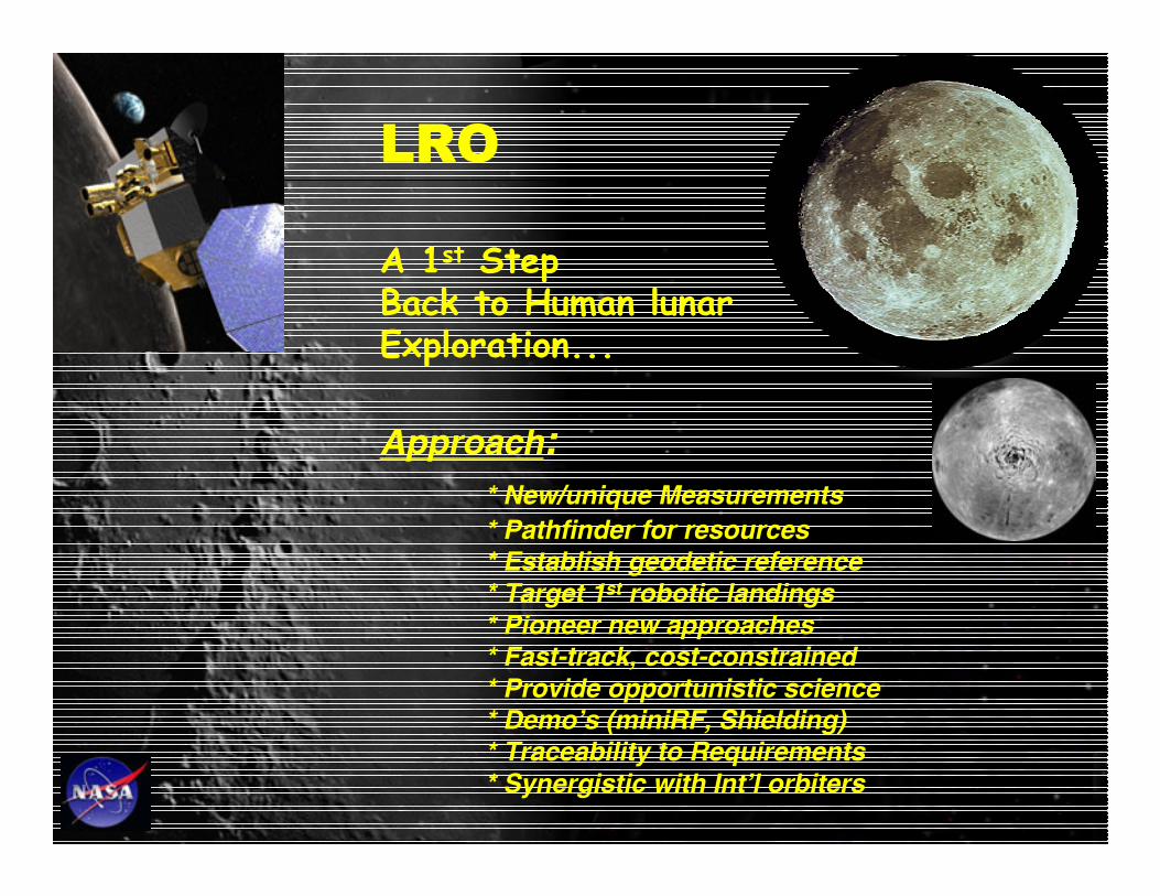
LRO
A 1st StepBack to Human lunarExploration...
Approach:* New/unique Measurements* Pathfinder for resources* Establish geodetic reference* Target 1st robotic landings* Pioneer new approaches* Fast-track, cost-constrained* Provide opportunistic science* Demo’s (miniRF, Shielding)* Traceability to Requirements* Synergistic with Int’l orbiters
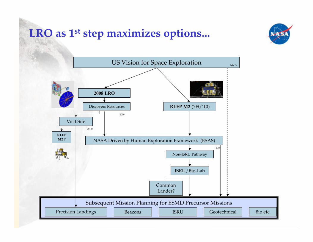
Subsequent Mission Planning for ESMD Precursor Missions
LRO as 1st step maximizes options...
US Vision for Space Exploration
2008 LRO
RLEP M2 (’09/’10)
NASA Driven by Human Exploration Framework (ESAS)
Discovers Resources
Visit Site
RLEP M2 ?
Precision Landings
Common Lander?
ISRU/Bio-Lab
Non-ISRU Pathway
2009
2012+
2005
Beacons ISRU Geotechnical Bio etc.
Feb ‘04
ILC2005, Toronto
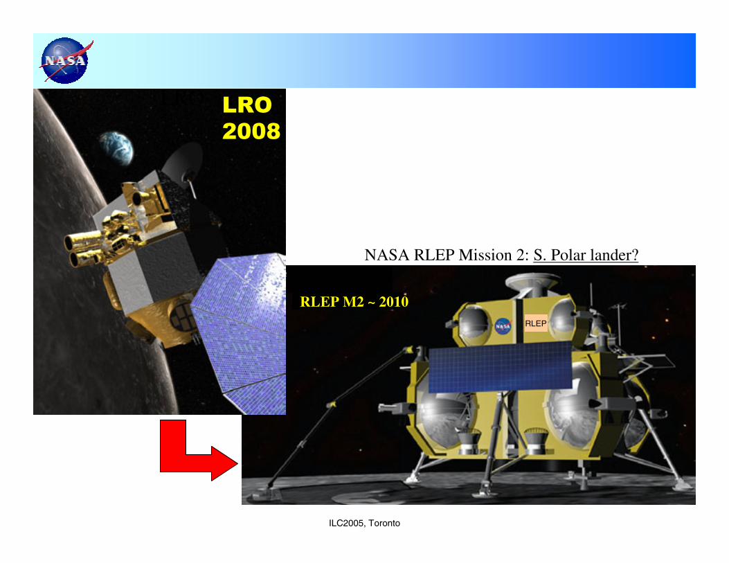
RLEP M2 ~ 2010RLEP
LRO LRO2008
NASA RLEP Mission 2: S. Polar lander?
ILC2005, Toronto
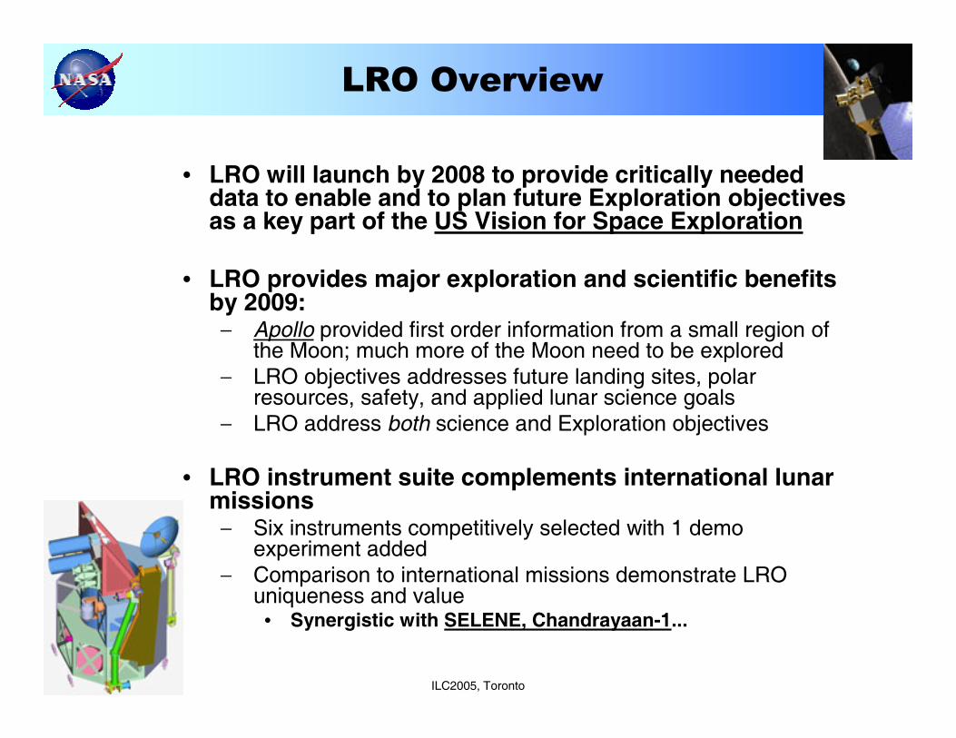
• LRO will launch by 2008 to provide critically needed data to enable and to plan future Exploration objectives as a key part of the US Vision for Space Exploration
• LRO provides major exploration and scientific benefits by 2009:− Apollo provided first order information from a small region of
the Moon; much more of the Moon need to be explored− LRO objectives addresses future landing sites, polar
resources, safety, and applied lunar science goals− LRO address both science and Exploration objectives
• LRO instrument suite complements international lunar missions− Six instruments competitively selected with 1 demo
experiment added− Comparison to international missions demonstrate LRO
uniqueness and value• Synergistic with SELENE, Chandrayaan-1...
LRO Overview
ILC2005, Toronto
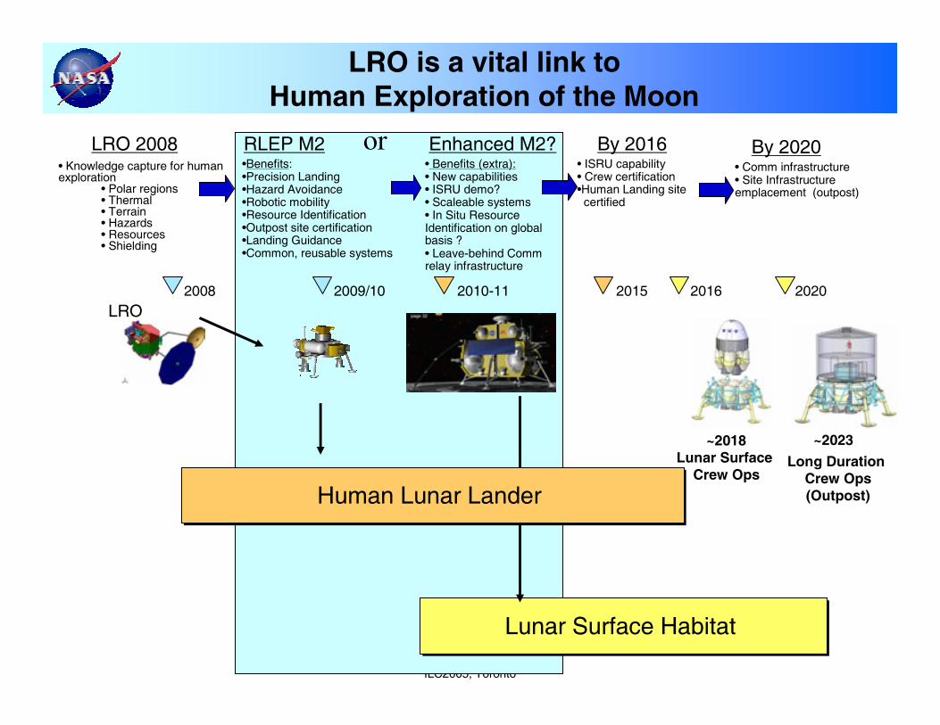
• Knowledge capture for human exploration
• Polar regions• Thermal• Terrain• Hazards• Resources• Shielding
RLEP M2•Benefits:•Precision Landing•Hazard Avoidance•Robotic mobility•Resource Identification•Outpost site certification•Landing Guidance•Common, reusable systems
LRO is a vital link to Human Exploration of the Moon
LRO 2008
Lunar Surface Habitat Lunar Surface Habitat
Long Duration Crew Ops(Outpost)
2009/10
• Comm infrastructure • Site Infrastructure emplacement (outpost)
By 2020
2016 2020
~2023
Enhanced M2?• Benefits (extra):• New capabilities• ISRU demo?• Scaleable systems• In Situ Resource Identification on global basis ?• Leave-behind Commrelay infrastructure
2010-11
• ISRU capability• Crew certification•Human Landing site certified
By 2016
2008
LRO2015
Human Lunar Lander Human Lunar Lander
~2018Lunar Surface
Crew Ops
or
ILC2005, Toronto
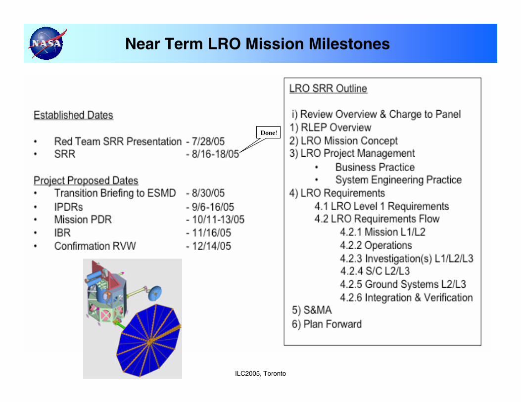
Near Term LRO Mission Milestones
Done!
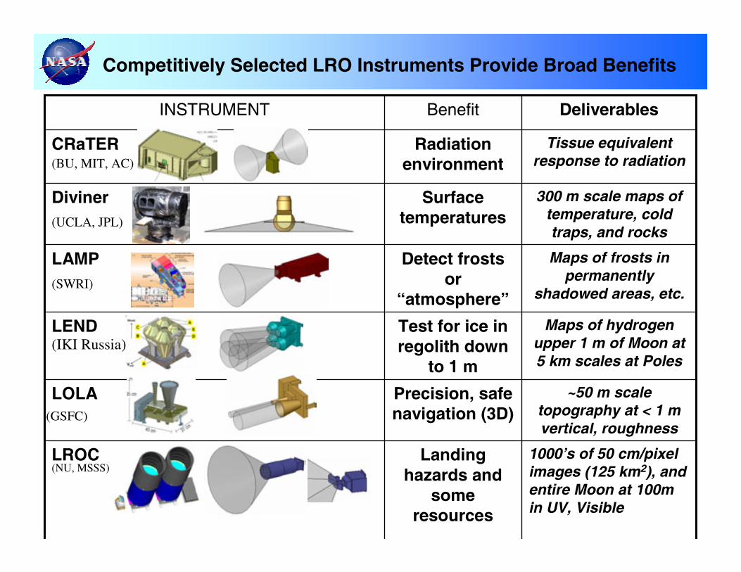
Competitively Selected LRO Instruments Provide Broad Benefits
1000’s of 50 cm/pixel images (125 km2), and entire Moon at 100m in UV, Visible
Landing hazards and
some resources
LROC
~50 m scale topography at < 1 m vertical, roughness
Precision, safe navigation (3D)
LOLA
Maps of hydrogen upper 1 m of Moon at 5 km scales at Poles
Test for ice in regolith down
to 1 m
LEND
Maps of frosts in permanently
shadowed areas, etc.
Detect frosts or
“atmosphere”
LAMP
300 m scale maps of temperature, cold traps, and rocks
Surface temperatures
Diviner
Tissue equivalent response to radiation
Radiation environment
CRaTER
DeliverablesBenefitINSTRUMENT
(BU, MIT, AC)
(UCLA, JPL)
(SWRI)
(IKI Russia)
(GSFC)
(NU, MSSS)
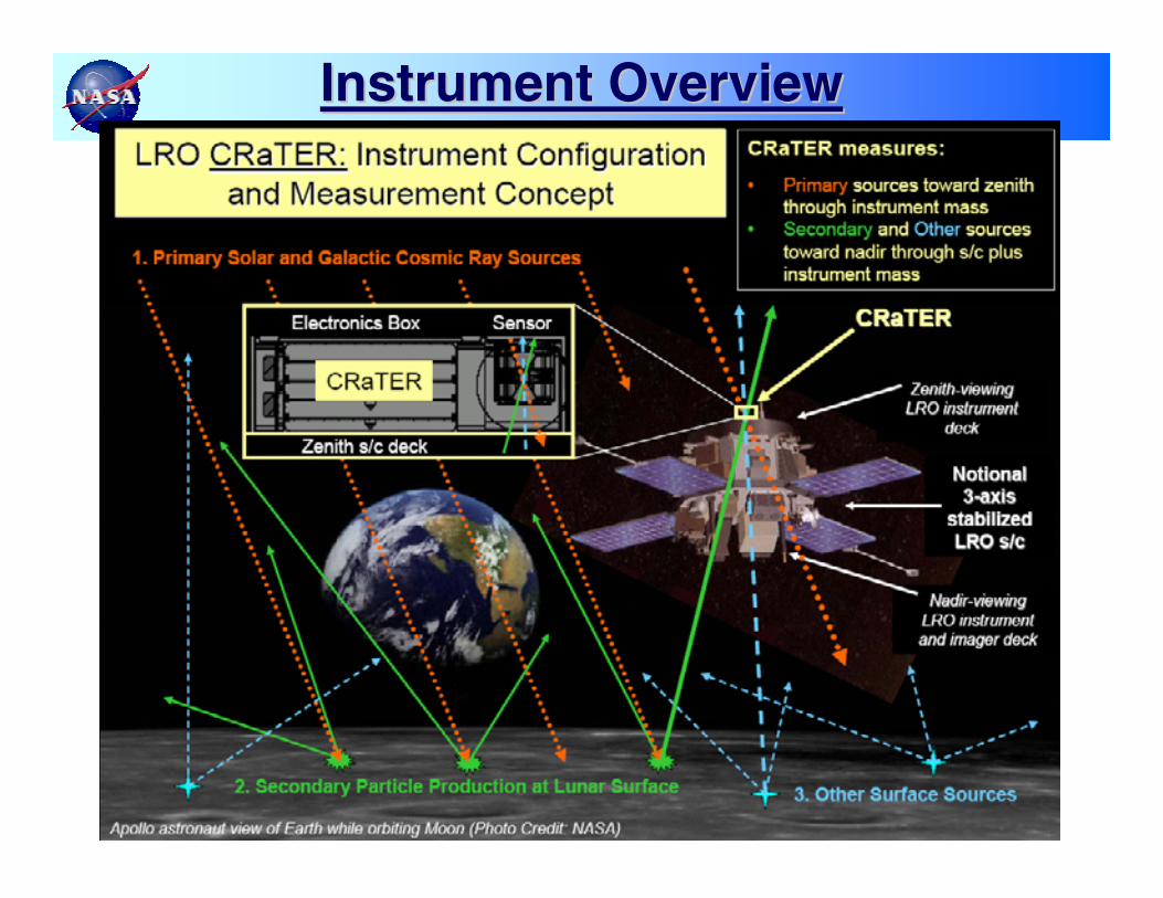
Instrument OverviewInstrument Overview
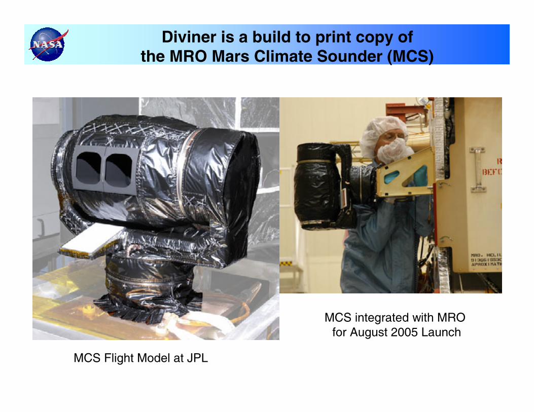
Diviner is a build to print copy of the MRO Mars Climate Sounder (MCS)
MCS Flight Model at JPL
MCS integrated with MRO for August 2005 Launch
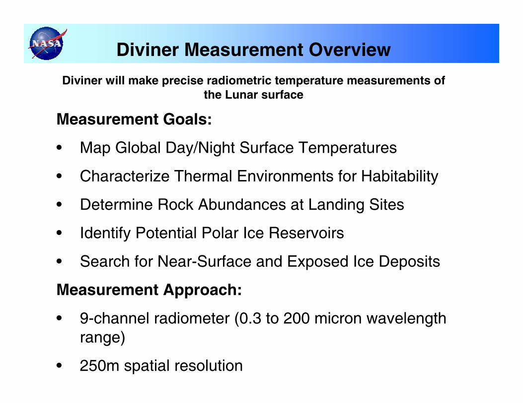
Diviner Measurement Overview
Diviner will make precise radiometric temperature measurements of the Lunar surface
Measurement Goals:
• Map Global Day/Night Surface Temperatures
• Characterize Thermal Environments for Habitability
• Determine Rock Abundances at Landing Sites
• Identify Potential Polar Ice Reservoirs
• Search for Near-Surface and Exposed Ice Deposits
Measurement Approach:
• 9-channel radiometer (0.3 to 200 micron wavelength range)
• 250m spatial resolution
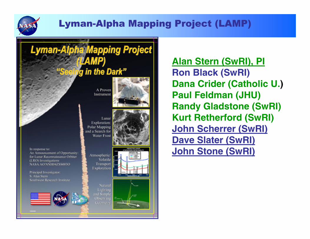
Lyman-Alpha Mapping Project (LAMP)
Alan Stern (SwRI), PIRon Black (SwRI)Dana Crider (Catholic U.)Paul Feldman (JHU)Randy Gladstone (SwRI)Kurt Retherford (SwRI)John Scherrer (SwRI)Dave Slater (SwRI)John Stone (SwRI)
LAMP Science/Measurement
LAMP will provide landform mapping (from Lyα albedos) at sub-km resolution in and around the permanently shadowed regions (PSRs) of the lunar surface.
LAMP will be used to identify and localize exposed water frost in PSRs.
LAMP will demonstrate the feasibility of using starlight and sky-glow for future surface mission applications.
LAMP will detect (or better constrain) the abundances of several atmospheric species.
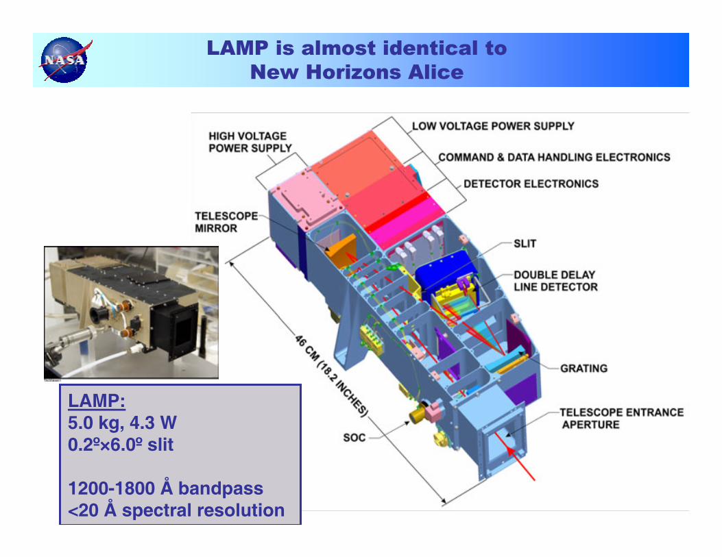
LAMP is almost identical to New Horizons Alice
LAMP:5.0 kg, 4.3 W0.2º×6.0º slit
1200-1800 Å bandpass<20 Å spectral resolution
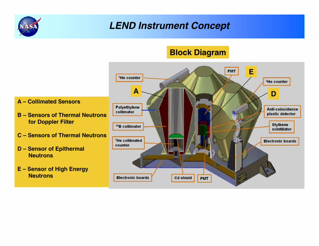
Block Diagram
A – Collimated Sensors
B – Sensors of Thermal Neutrons for Doppler Filter
C – Sensors of Thermal Neutrons
D – Sensor of Epithermal Neutrons
E – Sensor of High Energy Neutrons
A D
E
LEND Instrument Concept
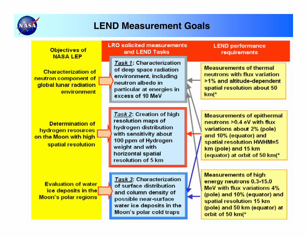
LEND Measurement Goals
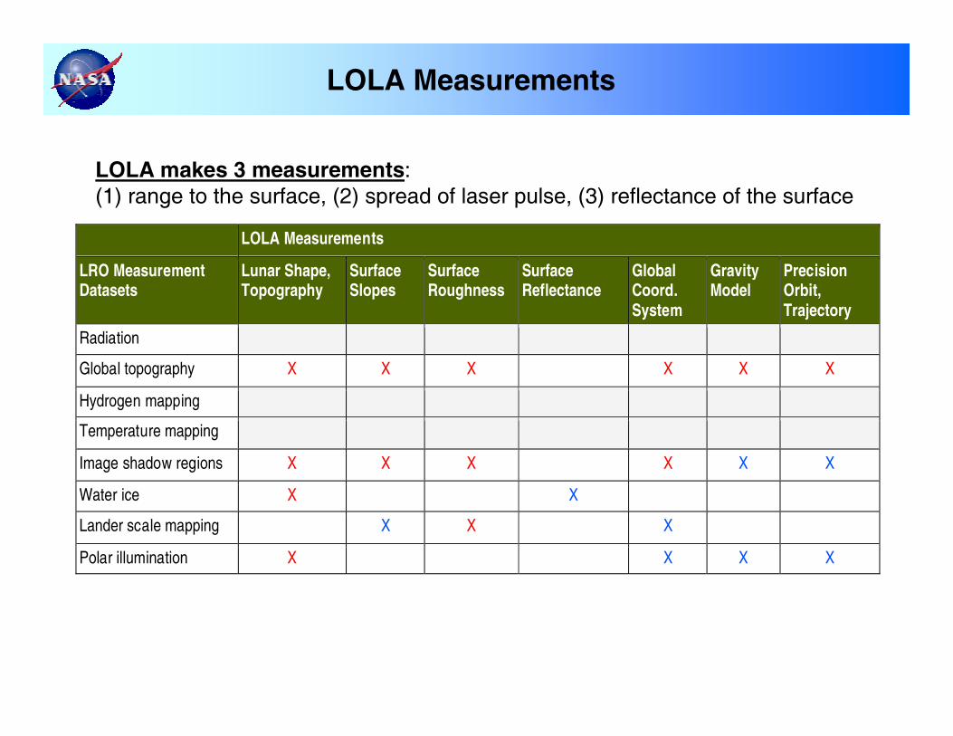
LOLA Measurements
LOLA Measurements
LRO Measurement Datasets
Lunar Shape, Topography
Surface Slopes
Surface Roughness
Surface Reflectance
Global Coord. System
Gravity Model
Precision Orbit, Trajectory
Radiation
Global topography X X X X X X
Hydrogen mapping
Temperature mapping
Image shadow regions X X X X X X
Water ice X X
Lander scale mapping X X X
Polar illumination X X X X
LOLA makes 3 measurements:(1) range to the surface, (2) spread of laser pulse, (3) reflectance of the surface
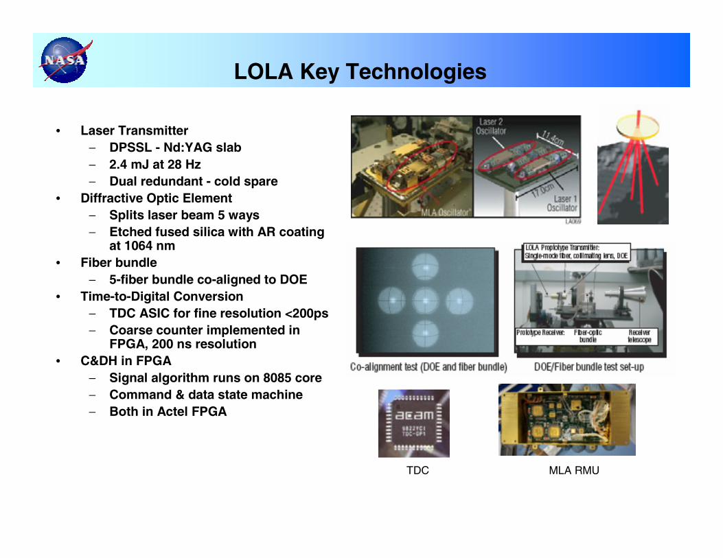
LOLA Key Technologies
• Laser Transmitter− DPSSL - Nd:YAG slab− 2.4 mJ at 28 Hz− Dual redundant - cold spare
• Diffractive Optic Element− Splits laser beam 5 ways− Etched fused silica with AR coating
at 1064 nm• Fiber bundle
− 5-fiber bundle co-aligned to DOE• Time-to-Digital Conversion
− TDC ASIC for fine resolution <200ps− Coarse counter implemented in
FPGA, 200 ns resolution• C&DH in FPGA
− Signal algorithm runs on 8085 core− Command & data state machine− Both in Actel FPGA
TDC MLA RMU
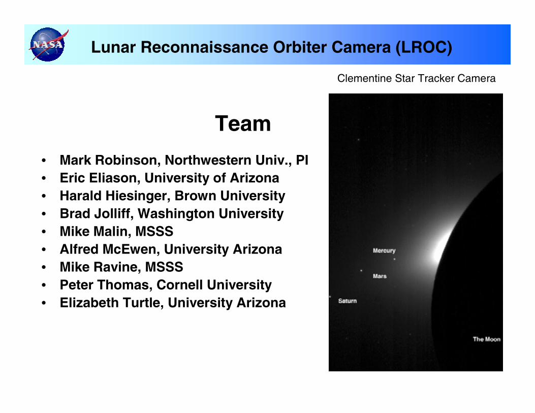
Lunar Reconnaissance Orbiter Camera (LROC)
Team
• Mark Robinson, Northwestern Univ., PI• Eric Eliason, University of Arizona• Harald Hiesinger, Brown University• Brad Jolliff, Washington University• Mike Malin, MSSS• Alfred McEwen, University Arizona• Mike Ravine, MSSS• Peter Thomas, Cornell University• Elizabeth Turtle, University Arizona
Clementine Star Tracker Camera
LROC Measurement Objectives
• Landing site identification and certification, with unambiguous identification of meter-scale hazards
• Unambiguous mapping of permanent shadows and sunlit regions
• Meter-scale mapping of polar regions with continuous illumination
• Overlapping observations to enable derivation of meter-scale topography
• Global multispectral imaging to map ilmenite and other minerals
• Global morphology base map• Characterize regolith properties• Determine current impact hazard by re-imaging 1-2
m/pixel Apollo images
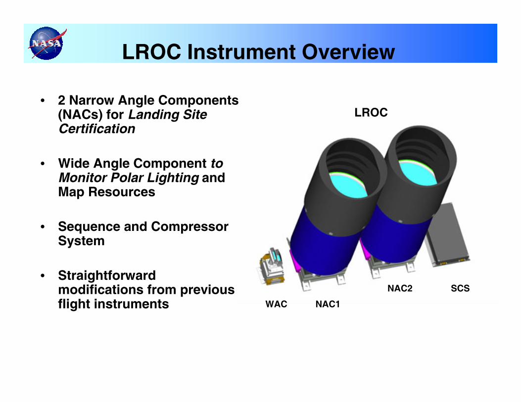
LROC Instrument Overview
WAC NAC1
NAC2 SCS
• 2 Narrow Angle Components (NACs) for Landing Site Certification
• Wide Angle Component to Monitor Polar Lighting and Map Resources
• Sequence and Compressor System
• Straightforward modifications from previous flight instruments
LROC
11/1/2005
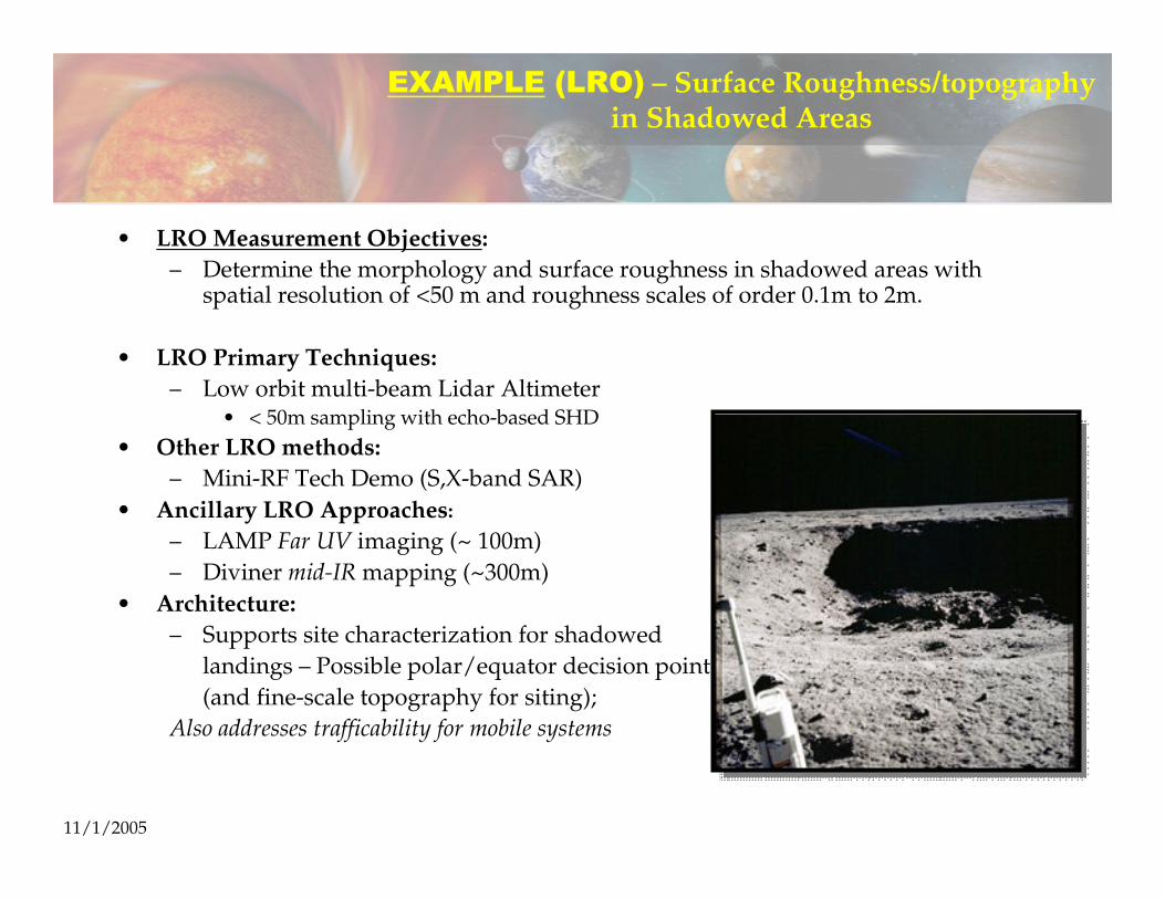
EXAMPLE (LRO) – Surface Roughness/topography in Shadowed Areas
• LRO Measurement Objectives:– Determine the morphology and surface roughness in shadowed areas with
spatial resolution of <50 m and roughness scales of order 0.1m to 2m.
• LRO Primary Techniques:– Low orbit multi-beam Lidar Altimeter
• < 50m sampling with echo-based SHD• Other LRO methods:
– Mini-RF Tech Demo (S,X-band SAR)• Ancillary LRO Approaches:
– LAMP Far UV imaging (~ 100m)– Diviner mid-IR mapping (~300m)
• Architecture:– Supports site characterization for shadowed
landings – Possible polar/equator decision point(and fine-scale topography for siting);
Also addresses trafficability for mobile systems
11/1/2005
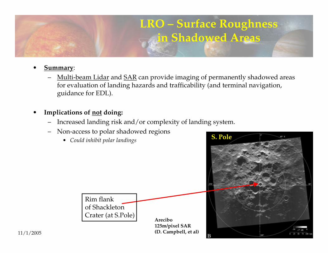
LRO – Surface Roughness in Shadowed Areas
• Summary:– Multi-beam Lidar and SAR can provide imaging of permanently shadowed areas
for evaluation of landing hazards and trafficability (and terminal navigation, guidance for EDL).
• Implications of not doing:– Increased landing risk and/or complexity of landing system.– Non-access to polar shadowed regions
• Could inhibit polar landings
Arecibo125m/pixel SAR(D. Campbell, et al)
S. Pole
Rim flankof ShackletonCrater (at S.Pole)
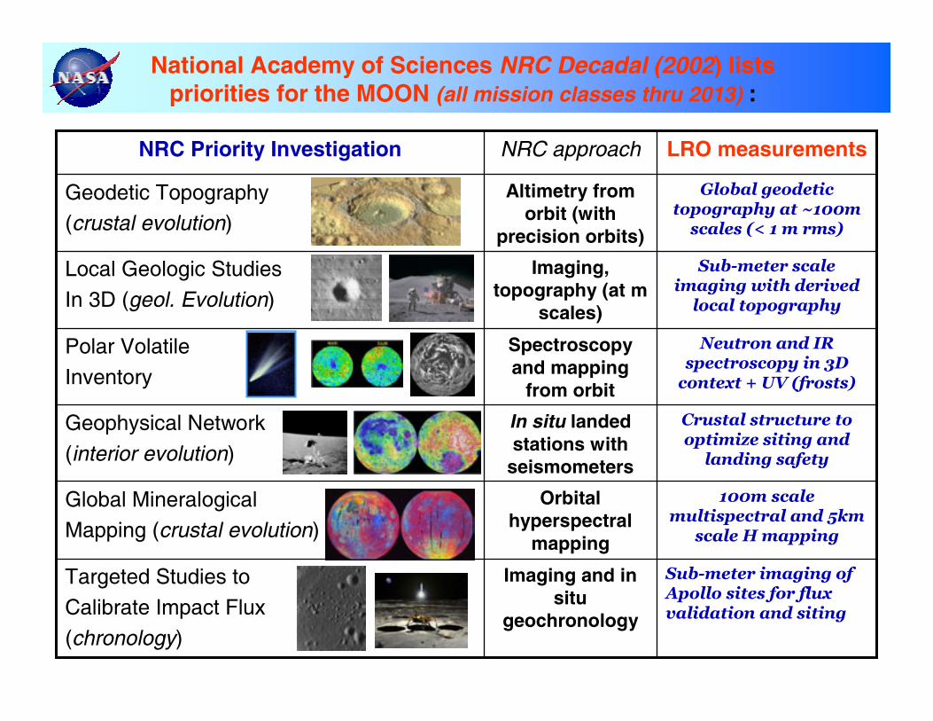
National Academy of Sciences NRC Decadal (2002) lists priorities for the MOON (all mission classes thru 2013) :
Sub-meter imaging of Apollo sites for flux validation and siting
Imaging and in situ
geochronology
Targeted Studies to
Calibrate Impact Flux
(chronology)
100m scale multispectral and 5km
scale H mapping
Orbital hyperspectral
mapping
Global Mineralogical Mapping (crustal evolution)
Crustal structure to optimize siting and
landing safety
In situ landed stations with
seismometers
Geophysical Network
(interior evolution)
Neutron and IR spectroscopy in 3D
context + UV (frosts)
Spectroscopy and mapping
from orbit
Polar Volatile
Inventory
Sub-meter scale imaging with derived
local topography
Imaging, topography (at m
scales)
Local Geologic Studies
In 3D (geol. Evolution)
Global geodetic topography at ~100m
scales (< 1 m rms)
Altimetry from orbit (with
precision orbits)
Geodetic Topography(crustal evolution)
LRO measurementsNRC approachNRC Priority Investigation
ILC2005, Toronto
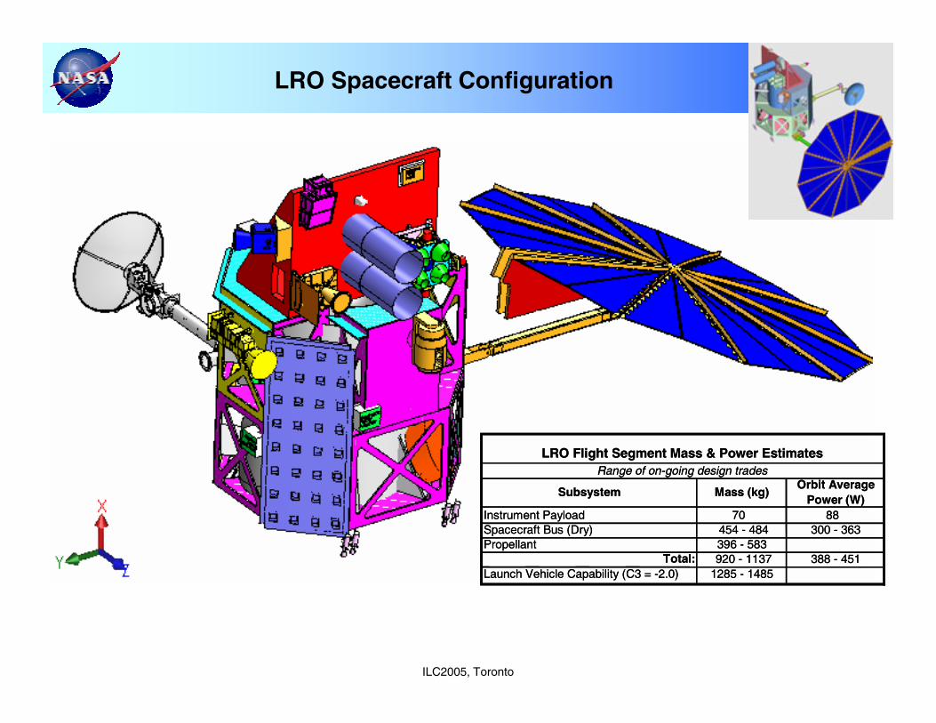
LRO Spacecraft Configuration
Subsystem Mass (kg)Orbit Average
Power (W)Instrument Payload 70 88Spacecraft Bus (Dry) 454 - 484 300 - 363Propellant 396 - 583
Total: 920 - 1137 388 - 451Launch Vehicle Capability (C3 = -2.0) 1285 - 1485
LRO Flight Segment Mass & Power EstimatesRange of on-going design trades
Subsystem Mass (kg)Orbit Average
Power (W)Instrument Payload 70 88Spacecraft Bus (Dry) 454 - 484 300 - 363Propellant 396 - 583
Total: 920 - 1137 388 - 451Launch Vehicle Capability (C3 = -2.0) 1285 - 1485
LRO Flight Segment Mass & Power EstimatesRange of on-going design trades
ILC2005, Toronto
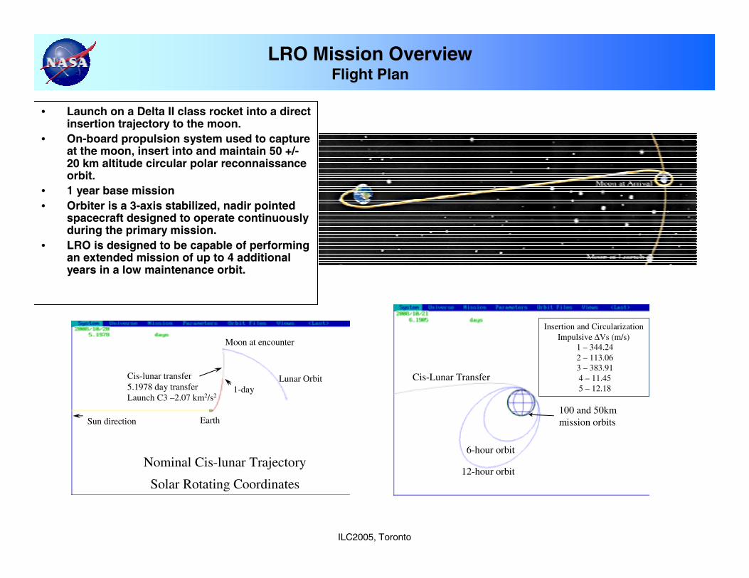
• Launch on a Delta II class rocket into a direct insertion trajectory to the moon.
• On-board propulsion system used to capture at the moon, insert into and maintain 50 +/-20 km altitude circular polar reconnaissance orbit.
• 1 year base mission• Orbiter is a 3-axis stabilized, nadir pointed
spacecraft designed to operate continuously during the primary mission.
• LRO is designed to be capable of performing an extended mission of up to 4 additional years in a low maintenance orbit.
LRO Mission OverviewFlight Plan
Solar Rotating Coordinates
Earth
Moon at encounter
Cis-lunar transfer5.1978 day transferLaunch C3 –2.07 km2/s2
1-dayLunar Orbit
Sun direction
Nominal Cis-lunar Trajectory
Cis-Lunar Transfer
12-hour orbit
6-hour orbit
100 and 50kmmission orbits
Insertion and CircularizationImpulsive ∆Vs (m/s)
1 – 344.242 – 113.063 – 383.914 – 11.455 – 12.18
ILC2005, Toronto
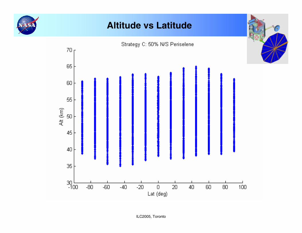
Altitude vs Latitude
ILC2005, Toronto
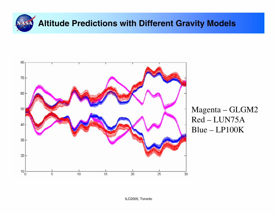
Altitude Predictions with Different Gravity Models
Magenta – GLGM2Red – LUN75ABlue – LP100K
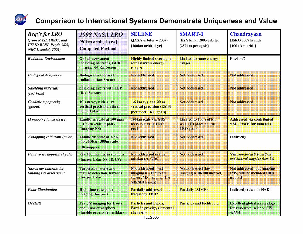
Excellent global mineralogy for resources, science (US MMM)
Particles and Fields, etc.Particles and Fields, Farside gravity, elemental chemistry
Far UV imaging for frosts and lunar atmosphere (farside gravity from lidar)
OTHER
Indirectly (via miniSAR)Partially (AIME)Partially addressed, but frequency TBD?
High time-rate polar imaging (Imagers)
Polar illumination
Not addressed, but imaging (MS) will be included (10’s m/pixel)
Not addressed (best imaging is 10-100 m/pixel)
Not addressed: best imaging is ~10m/pixel stereo, MS imaging (10+ VISNIR bands)
Targeted, meter-scale feature detection, hazards (Imager, Lidar)
Sub-meter imaging for landing site assessment
Via contributed S-band SAR and Mineral mapping from US
Not addressedNot addressed in this mission (cf. GRS)
~25-400m scales in shadows (Imager, Lidar, NS, IR, UV)
Putative ice deposits at poles
IndirectlyNot addressedNot addressedLandform scale at 3-5K (40-300K): ~300m scale
(IR mapper)
T mapping cold traps (polar)
Addressed via contributed SAR, MMM for minerals
Limited to 100’s of km scale (H) [does not meet LRO goals]
160km scale via GRS (does not meet LRO goals)
Landform scale at 100 ppm(~10 km scale at poles) (imaging NS)
H mapping to assess ice
Not addressedNot addressed1.6 km x, y at > 20 m vertical precision (RMS)[not meet LRO goals]
10’s m x,y, with < 1m vertical precision, attn to poles (Lidar)
Geodetic topography (global)
Not addressedNot addressedNot addressedShielding expt’s with TEP (Rad Sensor)
Shielding materials
(test-beds)
Not addressedNot addressedNot addressedBiological responses to radiation (Rad Sensor)
Biological Adaptation
Possible?Limited to some energy ranges
Highly limited overlap in some narrow energy ranges
Global assessment including neutrons, GCR (imaging NS, Rad Sensor)
Radiation Environment
Chandrayaan(ISRO 2007 launch)
[100+ km orbit]
SMART-1 (ESA lunar 2005 orbiter)
[250km periapsis]
SELENE (JAXA orbiter ~ 2007)
[100km orbit, 1 yr]
2008 NASA LRO[50km orbit, 1 yr+]Competed Payload
Reqt’s for LRO(from NASA ORDT, and ESMD RLEP Reqt’s 9/05; NRC Decadal, 2002)
ILC2005
Comparison to International Systems Demonstrate Uniqueness and Value
ILC2005, Toronto
LRO Status Report Summary
LRO completely addresses the majority of the National Academy of Sciences (NRC, 2002) scientific priorities for the Moon (that can be addressed from orbit)
LRO measurement sets will resolve key unknowns about the lunar crust (3D), sources and sinks of polar volatiles (i.e, the lunar “water” cycle”), and history of its earliest crustLRO will enable scientific discoveries about regions of the Moon (e.g. polar regions) not explored with Apollo (i.e., localization and inventory of water ice)LRO will put the MOON in a more complete context with respect to Earth and Mars (for Exploration)
♦ LRO fills in critical knowledge gaps of the Moon• Returning to the Moon without LRO would confine any future landing to near-side
equatorial sites where we have existing, but incomplete reconnaissance with known risk
• Reduces risks to all future landed missions (robotic and human)
• Supports timely strategic planning for future lunar operations (robotic and human).
♦ Data produced by LRO and follow-on robotic missions will reduce the cost and risk of the human lunar landing missions.
• Returning to the Moon without further robotic missions will pose additional uncertainties to future mission designs and likely result in expensive changes to the ESAS Surface Access Module and limit crew mission durations.
• Will result in lowering overall program cost by making lighter weight and more cost effective systems because of dramatically reduced environmental uncertainties, and optimized navigation trajectories (including polar localities)
ILC2005, Toronto
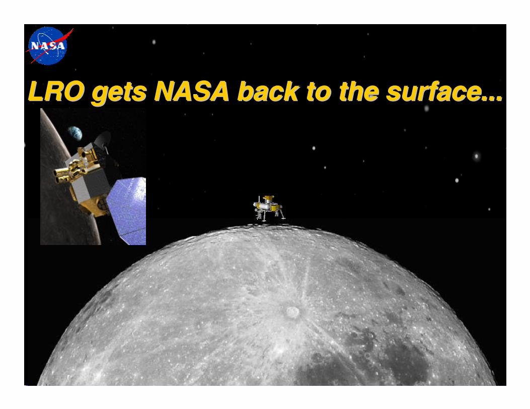
LRO gets NASA back to the surface...LRO gets NASA back to the surface...LRO gets NASA back to the surface...
ILC2005, Toronto
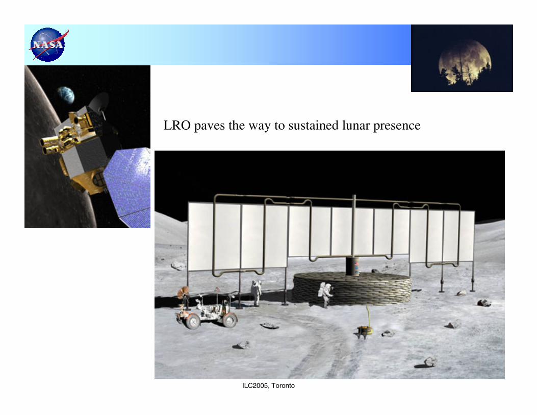
LRO paves the way to sustained lunar presence