Update 112015 ng-uk-gandb-090715-r1 V2 web · PDF fileAmerican Petroleum Institute API 2219:...
44
Grounding & Bonding Applications Issue 1 Controlling static electricity in hazardous areas Leading the way in hazardous area static control ® Gale Newson
Transcript of Update 112015 ng-uk-gandb-090715-r1 V2 web · PDF fileAmerican Petroleum Institute API 2219:...
Grounding& BondingApplications
Issue 1
Controllingstatic electricity inhazardous areas
Leading the wayin hazardous areastatic control
www.newson-gale.co.uk
®GaleNewson
Page Contents
1 Newson Gale - Precision and
Reliability.
2 Static electricity as a hazard,
legislation and codes of practise.
3-4 The basics of the hazard.
5 Real world scenarios.
5-6 Equipment Layers of Protection.
Grounding & Bonding 7
applications.
8-9 Grounding a road tanker with
system interlocks and indication.® Earth-Rite RTR™.
10-11 Truck mounted static ground
verification with system interlocks
and indication.® Earth-Rite MGV.
12-13 Grounding railcars, IBC’s and
drums with system interlocks and
indication.® Earth-Rite PLUS™.
14-15 Grounding interconnected plant
assemblies and piping with
system interlocks and indication.® Earth-Rite MULTIPOINT.
16-17 Grounding Type C FIBC with
system interlocks and indication.® Earth-Rite FIBC.
18-19 Panel mounted grounding with
system interlocks.® Earth-Rite OMEGA.
20-21 Grounding drums and containers
with indication.®Bond-Rite CLAMP.
22-23 Grounding drums and containers
with indication.®Bond-Rite REMOTE.
24-25 Bonding equipment with a
portable bonding device with
indication.®Bond-Rite EZ.
26-27 Hose testing and electrical
continuity testing with visual
indication.®OhmGuard .
28-29 Grounding drums and containers
with Factory Mutual / ATEX
approved clamps.
30-31 Sole-Mate - Footwear Tester.
Sole-Mate™.
32-33 Personnel grounding with
grounding straps.
Personnel Grounding Strap.
34 Guide to protection concepts and
codes for electrical equipment
operating in hazardous areas.
35 Comparison of European (ATEX),
North American (NEC & CEC) and
International (IECEx) Hazardous
Area Classification Systems.
Comparison of European and
North American Gas and Dust
Groups.
36-37 Interpreting certification and
approval codes for hazardous
area electrical equipment.
38 On-Going Maintenance of Static
Control Procedures and
Equipment.
39 Earth-Safe™.
40 Safety Checklist.
®Newson Gale
...your Trusted Advisor In Static Control
Contents
This Grounding and Bonding Application Handbook enables
you to identify the processes carried out at your site that
could pose a static ignition risk. As well as identifying the
problem, this Handbook identifies the right solution.
If you want to discuss a particular application or product feel free to submit an
enquiry via the enquiry buttons located in the PDF version or contact us via the
telephone or e-mail details provided on the back cover.
Enquiry
GaleNewson
®
Ranging from the loading of road tanker
trucks to emptying hand held cans, we
have a solution for virtually every
EX/HAZLOC process capable of
generating static electricity. Because we are
focussed on our customers, we understand
the challenges your processes and
installation options present you with. We
know that static electricity is not something
you deal with on a day-to-day basis and it’s
what separates us from other equipment
suppliers.
With Newson Gale, you gain access to our
extensive experience in static grounding
and bonding that empowers you and your
organisation to demonstrate compliance
with the recommended practices of
organisations like the International
Electrotechnical Commission, the National
Fire Protection Association and a wide
range of industry specific codes of practice,
that address the ignition hazards
associated with static electricity.
Owing to the thousands of applications we
have seen since the early 1980's two critical
ingredients underpin the performance of
our static control equipment: Precision
and Reliability.
Precision.
Our ground loop resistance monitoring
circuits are developed based on the
recommendations embedded in IEC,
NFPA and other industry guidelines.
We don’t use arbitrary values of
resistance. When our ground status
indicators go green, your operators are
working in compliance with industry
codes of practice.
Our grounding systems monitor the
ground loop through the equipment
requiring static grounding protection
back to verified grounding points, not the
grounding system itself. This guarantees
the removal of static electricity from the
process.
We continue to develop products that
are patented industry firsts. In 2012, the ®Earth-Rite MGV won the “Technical
Innovation of the Year” award at the
HazardEx awards ceremony.
Reliability.
Based on our extensive experience of a
wide range of EX/HAZLOC sectors we
develop and manufacture clamps, cables
and grounding systems that can cope
with the “industrial treatment” provided
by process operators.
In accordance with IEC 61508 our range ®of Earth-Rite systems are approved for
installation in Safety Integrity Level 2
rated environments.
We can offer multiple layers of protection
based on the scale of the static ignition
hazards present at your site.
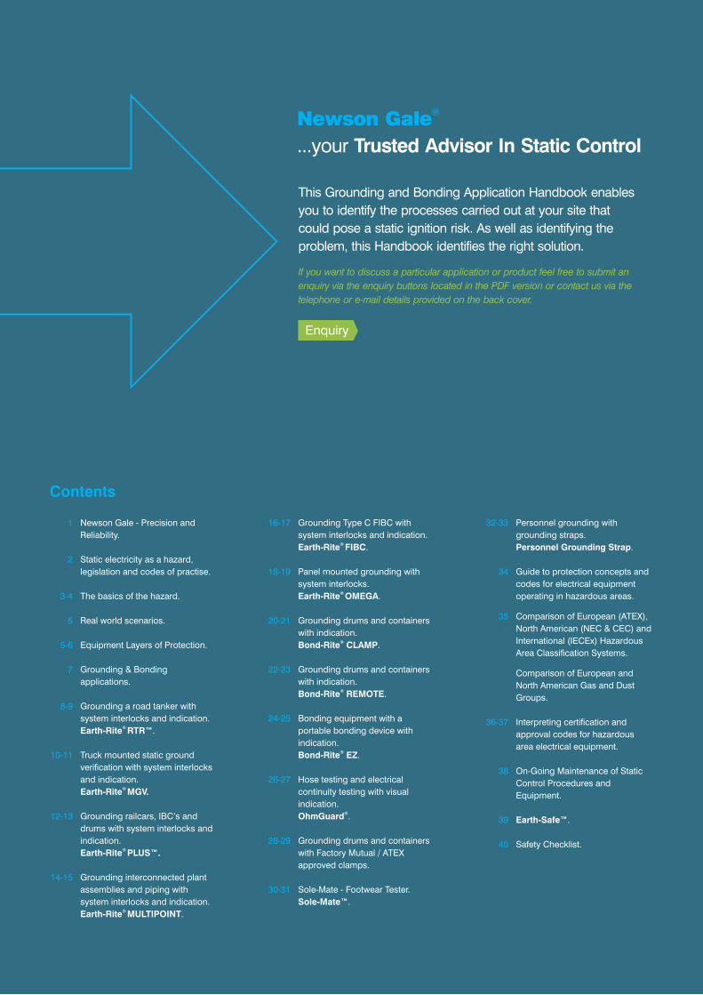
Newson Gale® is a company committed to eliminating the ignition hazards of static electricity.
Headquartered in Nottingham in the heart of the United Kingdom,
we develop and manufacture a range of hardware solutions
dedicated to ensuring static electricity is not an ignition source in
potentially flammable and combustible atmospheres.
1www.newson-gale.co.uk
IECEx SIL 2ATEX
< Back to Content
Static electricity as
a hazard
Static electricity can be described in a
number of different ways, but it is,
essentially, electricity stuck in one place.
In a normal electrical circuit, charges that
form an electrical current move through a
closed circuit in order to do something
beneficial, like power a computer or the
lighting in your house. In these circuits,
the charge always returns to the source
from which it has been supplied. Static
electricity is different. Because it is not
part of a closed circuit static electricity
can accumulate on plant equipment
ranging from road tankers to flexible
intermediate bulk containers.
Although static electricity is generally
regarded as a nuisance, in the hazardous
process industries, its effects can be
devastating. Discharges of static
electricity have been identified as the
ignition source for a broad range of
processes that cut right across a wide
selection of industry groups. It is as
potent as sparks resulting from
mechanical and electrical sources, and
yet, it is often underestimated, either due
to a lack of awareness of the risks it poses
or because of neglect and/or
complacency.
Legislation concerning
static electricity in the
hazardous process
industries
The threat posed by static electricity as an
ignition source is addressed in legislation
in both European and North American
occupational health and safety laws. In
Europe, Article 4 “Assessment of
explosion risks” of Directive 99/92/EC,
otherwise known as the ATEX Workplace
Directive, makes a clear reference to
“electrostatic discharges” as a potential
ignition source that must be considered
as part of the explosion risk assessment.
In the U.S., the Code of Federal
Regulations that addresses hazardous
location activities, 29 CFR Part 1910
“Occupational Safety and Health
Standards”, states that all ignition sources
potentially present in flammable
atmospheres, including static electricity,
shall be eliminated or controlled.
Section 10.12 of Canada’s Occupational
Health and Safety Regulations (SOR/86-
304) states that if a substance is
flammable and static electricity is a
potential ignition source that the employer
“shall implement the standards set out in
the United States National Fire
Protection Association, Inc. publication
NFPA 77, Recommended Practice on
Static Electricity.”
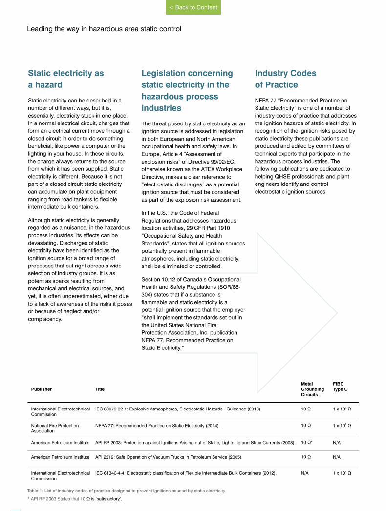
Industry Codes
of Practice
NFPA 77 “Recommended Practice on
Static Electricity” is one of a number of
industry codes of practice that addresses
the ignition hazards of static electricity. In
recognition of the ignition risks posed by
static electricity these publications are
produced and edited by committees of
technical experts that participate in the
hazardous process industries. The
following publications are dedicated to
helping QHSE professionals and plant
engineers identify and control
electrostatic ignition sources.
Leading the way in hazardous area static control
www.newson-gale.co.uk2
Publisher TitleMetal Grounding Circuits
FIBC Type C
International Electrotechnical Commission
IEC 60079-32-1: Explosive Atmospheres, Electrostatic Hazards - Guidance (2013). 10 Ω 71 x 10 Ω
National Fire Protection Association
NFPA 77: Recommended Practice on Static Electricity (2014). 10 Ω 71 x 10 Ω
American Petroleum Institute API RP 2003: Protection against Ignitions Arising out of Static, Lightning and Stray Currents (2008). 10 Ω* N/A
American Petroleum Institute API 2219: Safe Operation of Vacuum Trucks in Petroleum Service (2005). 10 Ω N/A
International Electrotechnical Commission
IEC 61340-4-4: Electrostatic classification of Flexible Intermediate Bulk Containers (2012). N/A 71 x 10 Ω
Table 1: List of industry codes of practice designed to prevent ignitions caused by static electricity.
* API RP 2003 States that 10 Ω is ‘satisfactory’.
< Back to Content
The basics of the hazard
When a high resistivity liquid, gas or
powder is constantly electrostatically
charged during processing operations
it will charge electrically isolated
conductive plant equipment and
materials that it is direct contact with,
or in close proximity to.
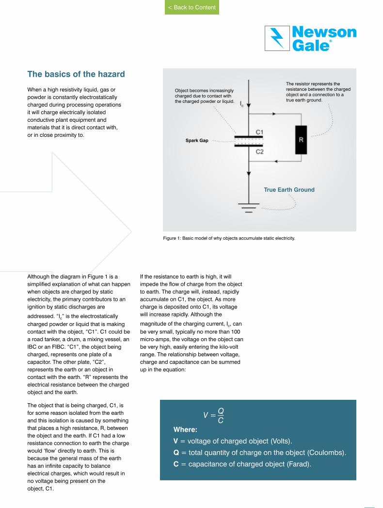
Although the diagram in Figure 1 is a
simplified explanation of what can happen
when objects are charged by static
electricity, the primary contributors to an
ignition by static discharges are
addressed. “I ” is the electrostatically c
charged powder or liquid that is making
contact with the object, “C1”. C1 could be
a road tanker, a drum, a mixing vessel, an
IBC or an FIBC. “C1”, the object being
charged, represents one plate of a
capacitor. The other plate, “C2”,
represents the earth or an object in
contact with the earth. “R” represents the
electrical resistance between the charged
object and the earth.
The object that is being charged, C1, is
for some reason isolated from the earth
and this isolation is caused by something
that places a high resistance, R, between
the object and the earth. If C1 had a low
resistance connection to earth the charge
would ‘flow’ directly to earth. This is
because the general mass of the earth
has an infinite capacity to balance
electrical charges, which would result in
no voltage being present on the
object, C1.
If the resistance to earth is high, it will
impede the flow of charge from the object
to earth. The charge will, instead, rapidly
accumulate on C1, the object. As more
charge is deposited onto C1, its voltage
will increase rapidly. Although the
magnitude of the charging current, I , can c
be very small, typically no more than 100
micro-amps, the voltage on the object can
be very high, easily entering the kilo-volt
range. The relationship between voltage,
charge and capacitance can be summed
up in the equation:
Object becomes increasingly charged due to contact with the charged powder or liquid.
The resistor represents the resistance between the charged object and a connection to a true earth ground.
Spark Gap
True Earth Ground
Figure 1: Basic model of why objects accumulate static electricity.
V =QC
Where:
V = voltage of charged object (Volts).
Q = total quantity of charge on the object (Coulombs).
C = capacitance of charged object (Farad).
GaleNewson
®
www.newson-gale.co.uk 3
< Back to Content
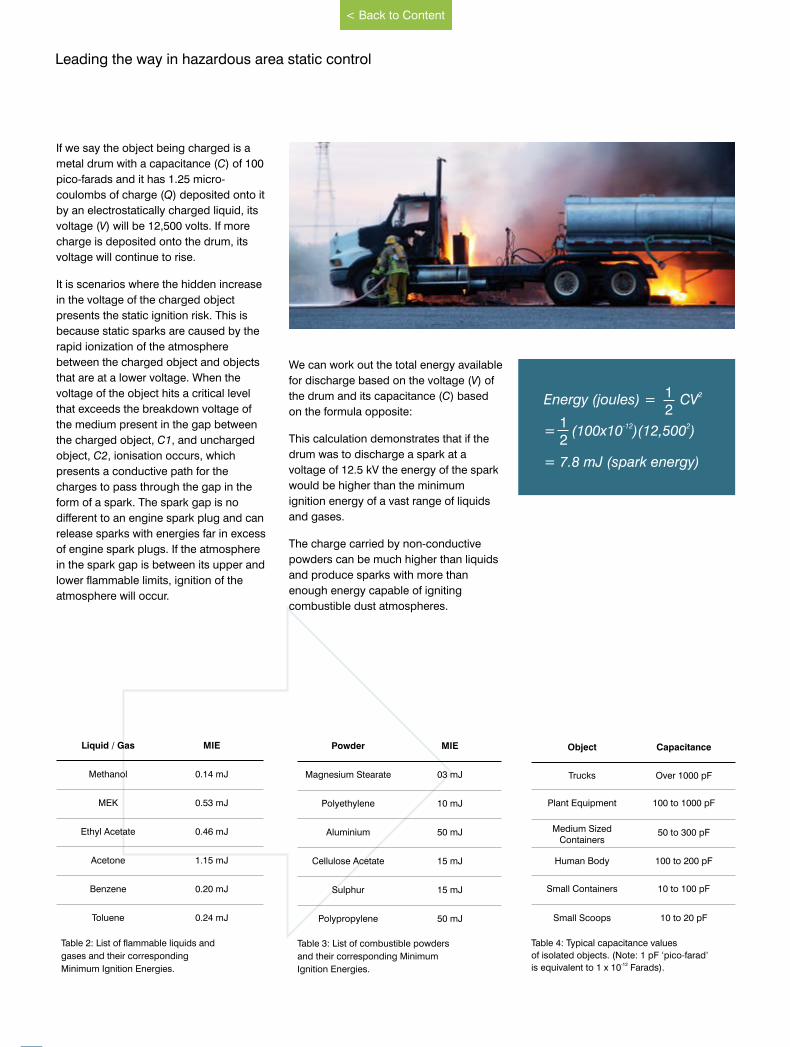
If we say the object being charged is a
metal drum with a capacitance (C) of 100
pico-farads and it has 1.25 micro-
coulombs of charge (Q) deposited onto it
by an electrostatically charged liquid, its
voltage (V) will be 12,500 volts. If more
charge is deposited onto the drum, its
voltage will continue to rise.
It is scenarios where the hidden increase
in the voltage of the charged object
presents the static ignition risk. This is
because static sparks are caused by the
rapid ionization of the atmosphere
between the charged object and objects
that are at a lower voltage. When the
voltage of the object hits a critical level
that exceeds the breakdown voltage of
the medium present in the gap between
the charged object, C1, and uncharged
object, C2, ionisation occurs, which
presents a conductive path for the
charges to pass through the gap in the
form of a spark. The spark gap is no
different to an engine spark plug and can
release sparks with energies far in excess
of engine spark plugs. If the atmosphere
in the spark gap is between its upper and
lower flammable limits, ignition of the
atmosphere will occur.
We can work out the total energy available
for discharge based on the voltage (V) of
the drum and its capacitance (C) based
on the formula opposite:
This calculation demonstrates that if the
drum was to discharge a spark at a
voltage of 12.5 kV the energy of the spark
would be higher than the minimum
ignition energy of a vast range of liquids
and gases.
The charge carried by non-conductive
powders can be much higher than liquids
and produce sparks with more than
enough energy capable of igniting
combustible dust atmospheres.
Liquid / Gas MIE
Methanol 0.14 mJ
MEK 0.53 mJ
Ethyl Acetate 0.46 mJ
Acetone 1.15 mJ
Benzene 0.20 mJ
Toluene 0.24 mJ
Table 2: List of flammable liquids and
gases and their corresponding
Minimum Ignition Energies.
2Energy (joules) = CV
-12 2= (100x10 )(12,500 )
= 7.8 mJ (spark energy)
12
12
Powder MIE
Magnesium Stearate 03 mJ
Polyethylene 10 mJ
Aluminium 50 mJ
Cellulose Acetate 15 mJ
Sulphur 15 mJ
Polypropylene 50 mJ
Object Capacitance
Trucks Over 1000 pF
Plant Equipment 100 to 1000 pF
Medium Sized Containers
50 to 300 pF
Human Body 100 to 200 pF
Small Containers 10 to 100 pF
Small Scoops 10 to 20 pF
Table 4: Typical capacitance values
of isolated objects. (Note: 1 pF ‘pico-farad’-12is equivalent to 1 x 10 Farads).
Table 3: List of combustible powders
and their corresponding Minimum
Ignition Energies.
Leading the way in hazardous area static control
4 www.newson-gale.co.uk
< Back to Content
Real world scenarios
So what scenarios can give rise to
situations where static charges
accumulate on equipment used in
EX/HAZLOC atmospheres?
As described in Figure 1 the objective is
to ensure the equipment’s voltage does
not rise during operations. We know
charge accumulation can only take place
if there is a resistance present between
the equipment and general mass of earth.
Connections to the mass of the earth
should be provided by high integrity earth
grounds present on the site. These high
integrity earth grounds should be
providing protection against lightning
strikes and electrical faults with plant
equipment, and will provide a satisfactory
path for static electricity.
What we need to do is ensure any plant
equipment, whether it is mobile or part of
fixed plant, never becomes isolated from
our designated earth grounding points.
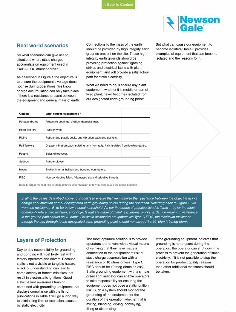
But what can cause our equipment to
become isolated? Table 5 provides
examples of equipment that can become
isolated and the reasons for it.
Layers of Protection
Day to day responsibility for grounding
and bonding will most likely rest with
factory operators and drivers. Because
static is not a visible or tangible hazard,
a lack of understanding can lead to
complacency or honest mistakes that
result in electrostatic ignitions. Good
static hazard awareness training
combined with grounding equipment that
displays compliance with the list of
publications in Table 1 will go a long way
to eliminating fires or explosions caused
by static electricity.
The most optimum solution is to provide
operators and drivers with a visual means
of verifying that they have made a
connection to the equipment at risk of
static charge accumulation with a
resistance of 10 ohms or less (Type C
FIBC should be 10 meg-ohms or less).
Static grounding equipment with a simple
green light indicator can enable operators
to take responsibility for ensuring the
equipment does not pose a static ignition
risk. Such a system should monitor the
grounding of the equipment for the
duration of the operation whether that is
mixing, blending, drying, conveying,
filling or dispensing.
If the grounding equipment indicates that
grounding is not present during the
operation, the operator can shut down the
process to prevent the generation of static
electricity. If it is not possible to stop the
operation for product quality reasons,
then other additional measures should
be taken.
Objects What causes capacitance?
Portable drums Protective coatings, product deposits, rust.
Road Tankers Rubber tyres.
Piping Rubber and plastic seals, anti-vibration pads and gaskets.
Rail Tankers Grease, vibration pads isolating tank from rails. Rails isolated from loading gantry.
People Soles of footwear.
Scoops Rubber gloves.
Hoses Broken internal helixes and bonding connectors.
FIBC Non-conductive fabric / damaged static dissipative threads.
In all of the cases described above, our goal is to ensure that we minimise the resistance between the object at risk of
charge accumulation and our designated earth grounding points during the operation. Referring back to Figure 1, we
want the resistance ‘R’ to be below a certain threshold. As per the codes of practice listed in Table 1, by far the most
commonly referenced resistance for objects that are made of metal, e.g. drums, trucks, IBCs, the maximum resistance
in the ground path should be 10 ohms. For static dissipative equipment like Type C FIBC, the maximum resistance 7through the bag through to the designated earth grounding point should not exceed 1 x 10 ohm (10 meg-ohm).
Table 5: Equipment at risk of static charge accumulation and what can cause electrical isolation.
GaleNewson
®
5www.newson-gale.co.uk
< Back to Content
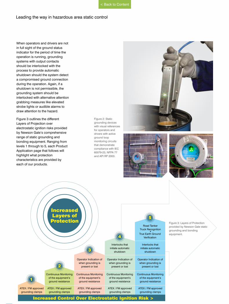
When operators and drivers are not
in full sight of the ground status
indicator for the period of time the
operation is running, grounding
systems with output contacts
should be interlocked with the
process to provide automatic
shutdown should the system detect
a compromised ground connection
during the operation. Again, if a
shutdown is not permissible, the
grounding system should be
interlocked with alternative attention
grabbing measures like elevated
strobe lights or audible alarms to
draw attention to the hazard.
Figure 3 outlines the different
Layers of Projection over
electrostatic ignition risks provided
by Newson Gale’s comprehensive
range of static grounding and
bonding equipment. Ranging from
levels 1 through to 5, each Product
Application page that follows will
highlight what protection
characteristics are provided by
each of our products.
Figure 2: Static
grounding devices
with visual references
for operators and
drivers with active
ground loop
monitoring circuits
that demonstrate
compliance with IEC
60079-23, NFPA 77
and API RP 2003.
Figure 3: Layers of Protection
provided by Newson Gale static
grounding and bonding
equipment.
ATEX / FM approved
grounding clamps
Continuous Monitoring
of the equipment’s
ground resistance
Operator Indication of
when grounding is
present or lost
ATEX / FM approved
grounding clamps
Continuous Monitoring
of the equipment’s
ground resistance
Operator Indication of
when grounding is
present or lost
Interlocks that
initiate automatic
shutdown
Road Tanker
Truck Recognition
True Earth Ground
Verification
ATEX / FM approved
grounding clamps
Continuous Monitoring
of the equipment’s
ground resistance
ATEX / FM approved
grounding clamps
Continuous Monitoring
of the equipment’s
ground resistance
Operator Indication of
when grounding is
present or lost
Interlocks that
initiate automatic
shutdown
ATEX / FM approved
grounding clamps
+
Increased Control Over Electrostatic Ignition Risk >
5
4
3
2
1
IncreasedLayers of
Protection
Leading the way in hazardous area static control
6 www.newson-gale.co.uk
< Back to Content
GaleNewson
®
7
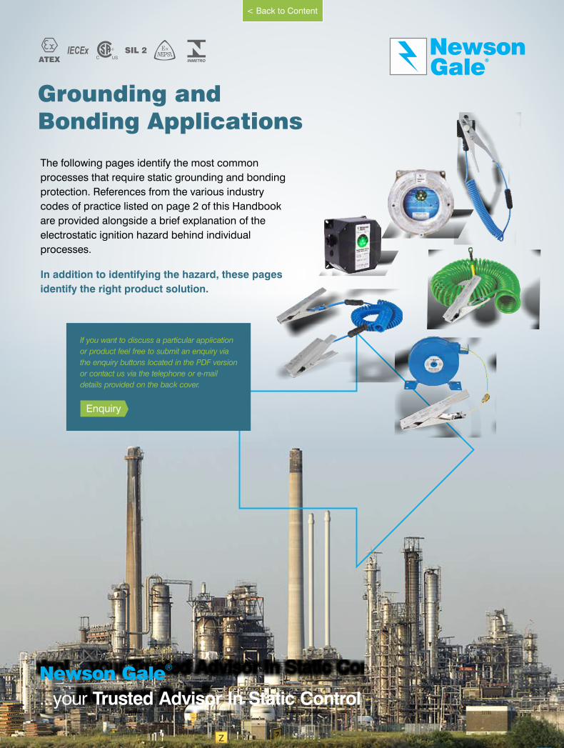
Grounding andBonding Applications
The following pages identify the most common
processes that require static grounding and bonding
protection. References from the various industry
codes of practice listed on page 2 of this Handbook
are provided alongside a brief explanation of the
electrostatic ignition hazard behind individual
processes.
In addition to identifying the hazard, these pages
identify the right product solution.
IECEx SIL 2ATEX
®Newson Gale
...your Trusted Advisor In Static Control
www.newson-gale.co.uk
< Back to Content
If you want to discuss a particular application
or product feel free to submit an enquiry via
the enquiry buttons located in the PDF version
or contact us via the telephone or e-mail
details provided on the back cover.
Enquiry
8
Leading the way in hazardous area static control
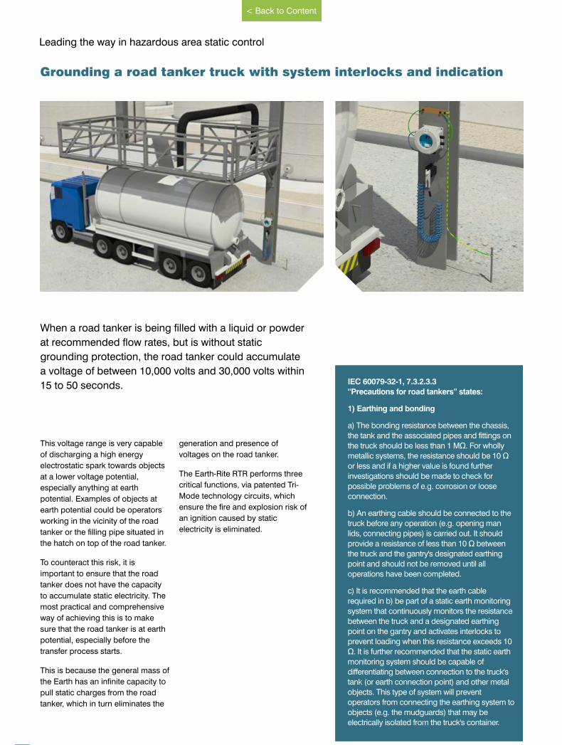
When a road tanker is being filled with a liquid or powder
at recommended flow rates, but is without static
grounding protection, the road tanker could accumulate
a voltage of between 10,000 volts and 30,000 volts within
15 to 50 seconds.
This voltage range is very capable
of discharging a high energy
electrostatic spark towards objects
at a lower voltage potential,
especially anything at earth
potential. Examples of objects at
earth potential could be operators
working in the vicinity of the road
tanker or the filling pipe situated in
the hatch on top of the road tanker.
To counteract this risk, it is
important to ensure that the road
tanker does not have the capacity
to accumulate static electricity. The
most practical and comprehensive
way of achieving this is to make
sure that the road tanker is at earth
potential, especially before the
transfer process starts.
This is because the general mass of
the Earth has an infinite capacity to
pull static charges from the road
tanker, which in turn eliminates the
generation and presence of
voltages on the road tanker.
The Earth-Rite RTR performs three
critical functions, via patented Tri-
Mode technology circuits, which
ensure the fire and explosion risk of
an ignition caused by static
electricity is eliminated.
Grounding a road tanker truck with system interlocks and indication
IEC 60079-32-1, 7.3.2.3.3
“Precautions for road tankers” states:
1) Earthing and bonding
a) The bonding resistance between the chassis,
the tank and the associated pipes and fittings on
the truck should be less than 1 MΩ. For wholly
metallic systems, the resistance should be 10 Ω
or less and if a higher value is found further
investigations should be made to check for
possible problems of e.g. corrosion or loose
connection.
b) An earthing cable should be connected to the
truck before any operation (e.g. opening man
lids, connecting pipes) is carried out. It should
provide a resistance of less than 10 Ω between
the truck and the gantry's designated earthing
point and should not be removed until all
operations have been completed.
c) It is recommended that the earth cable
required in b) be part of a static earth monitoring
system that continuously monitors the resistance
between the truck and a designated earthing
point on the gantry and activates interlocks to
prevent loading when this resistance exceeds 10
Ω. It is further recommended that the static earth
monitoring system should be capable of
differentiating between connection to the truck's
tank (or earth connection point) and other metal
objects. This type of system will prevent
operators from connecting the earthing system to
objects (e.g. the mudguards) that may be
electrically isolated from the truck's container.
www.newson-gale.co.uk
< Back to Content
9
GaleNewson
®
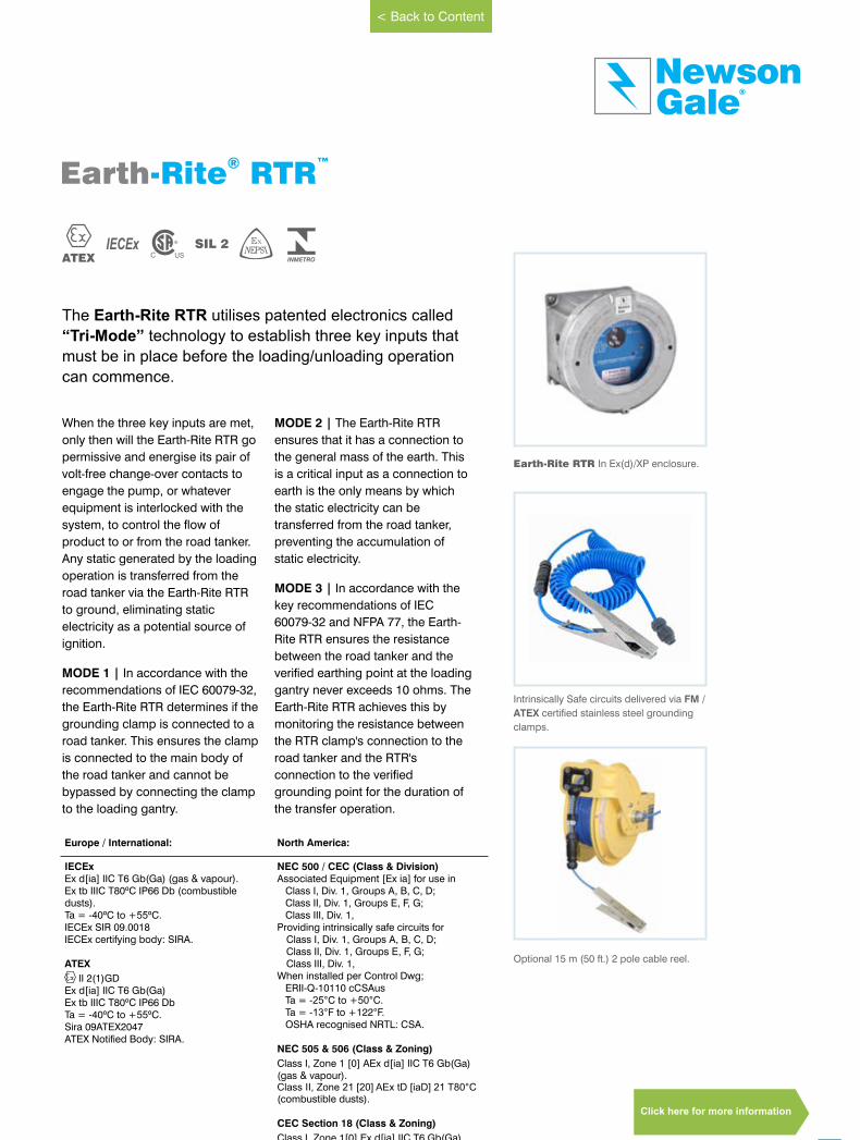
The Earth-Rite RTR utilises patented electronics called
“Tri-Mode” technology to establish three key inputs that
must be in place before the loading/unloading operation
can commence.
When the three key inputs are met,
only then will the Earth-Rite RTR go
permissive and energise its pair of
volt-free change-over contacts to
engage the pump, or whatever
equipment is interlocked with the
system, to control the flow of
product to or from the road tanker.
Any static generated by the loading
operation is transferred from the
road tanker via the Earth-Rite RTR
to ground, eliminating static
electricity as a potential source of
ignition.
MODE 1 | In accordance with the
recommendations of IEC 60079-32,
the Earth-Rite RTR determines if the
grounding clamp is connected to a
road tanker. This ensures the clamp
is connected to the main body of
the road tanker and cannot be
bypassed by connecting the clamp
to the loading gantry.
MODE 2 | The Earth-Rite RTR
ensures that it has a connection to
the general mass of the earth. This
is a critical input as a connection to
earth is the only means by which
the static electricity can be
transferred from the road tanker,
preventing the accumulation of
static electricity.
MODE 3 | In accordance with the
key recommendations of IEC
60079-32 and NFPA 77, the Earth-
Rite RTR ensures the resistance
between the road tanker and the
verified earthing point at the loading
gantry never exceeds 10 ohms. The
Earth-Rite RTR achieves this by
monitoring the resistance between
the RTR clamp's connection to the
road tanker and the RTR's
connection to the verified
grounding point for the duration of
the transfer operation.
IECEx SIL 2ATEX
Earth ™-Rite RTR®
Earth-Rite RTR In Ex(d)/XP enclosure.
Intrinsically Safe circuits delivered via FM /
ATEX certified stainless steel grounding
clamps.
Optional 15 m (50 ft.) 2 pole cable reel.
www.newson-gale.co.uk
Europe / International: North America:
IECExEx d[ia] IIC T6 Gb(Ga) (gas & vapour).Ex tb IIIC T80ºC IP66 Db (combustible dusts).Ta = -40ºC to +55ºC.IECEx SIR 09.0018IECEx certifying body: SIRA.
ATEX
II 2(1)GDEx d[ia] IIC T6 Gb(Ga) Ex tb IIIC T80ºC IP66 Db Ta = -40ºC to +55ºC.Sira 09ATEX2047ATEX Notified Body: SIRA.
NEC 500 / CEC (Class & Division)Associated Equipment [Ex ia] for use in
Class I, Div. 1, Groups A, B, C, D;Class II, Div. 1, Groups E, F, G;Class III, Div. 1,
Providing intrinsically safe circuits forClass I, Div. 1, Groups A, B, C, D;Class II, Div. 1, Groups E, F, G;Class III, Div. 1,
When installed per Control Dwg;ERII-Q-10110 cCSAusTa = -25°C to +50°C.Ta = -13°F to +122°F.OSHA recognised NRTL: CSA.
NEC 505 & 506 (Class & Zoning)
Class I, Zone 1 [0] AEx d[ia] IIC T6 Gb(Ga) (gas & vapour).Class II, Zone 21 [20] AEx tD [iaD] 21 T80°C (combustible dusts).
CEC Section 18 (Class & Zoning)
Class I, Zone 1[0] Ex d[ia] IIC T6 Gb(Ga)DIP A21, IP66, T80ºC
Click here for more information
< Back to Content
10
Leading the way in hazardous area static control
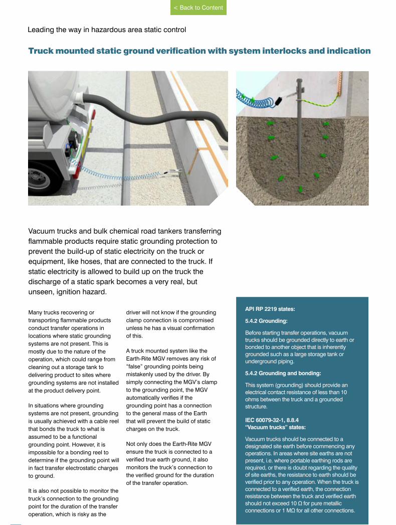
Vacuum trucks and bulk chemical road tankers transferring
flammable products require static grounding protection to
prevent the build-up of static electricity on the truck or
equipment, like hoses, that are connected to the truck. If
static electricity is allowed to build up on the truck the
discharge of a static spark becomes a very real, but
unseen, ignition hazard.
Many trucks recovering or
transporting flammable products
conduct transfer operations in
locations where static grounding
systems are not present. This is
mostly due to the nature of the
operation, which could range from
cleaning out a storage tank to
delivering product to sites where
grounding systems are not installed
at the product delivery point.
In situations where grounding
systems are not present, grounding
is usually achieved with a cable reel
that bonds the truck to what is
assumed to be a functional
grounding point. However, it is
impossible for a bonding reel to
determine if the grounding point will
in fact transfer electrostatic charges
to ground.
It is also not possible to monitor the
truck’s connection to the grounding
point for the duration of the transfer
operation, which is risky as the
driver will not know if the grounding
clamp connection is compromised
unless he has a visual confirmation
of this.
A truck mounted system like the
Earth-Rite MGV removes any risk of
“false” grounding points being
mistakenly used by the driver. By
simply connecting the MGV’s clamp
to the grounding point, the MGV
automatically verifies if the
grounding point has a connection
to the general mass of the Earth
that will prevent the build of static
charges on the truck.
Not only does the Earth-Rite MGV
ensure the truck is connected to a
verified true earth ground, it also
monitors the truck’s connection to
the verified ground for the duration
of the transfer operation.
Truck mounted static ground verification with system interlocks and indication
API RP 2219 states:
5.4.2 Grounding:
Before starting transfer operations, vacuum
trucks should be grounded directly to earth or
bonded to another object that is inherently
grounded such as a large storage tank or
underground piping.
5.4.2 Grounding and bonding:
This system (grounding) should provide an
electrical contact resistance of less than 10
ohms between the truck and a grounded
structure.
IEC 60079-32-1, 8.8.4
“Vacuum trucks” states:
Vacuum trucks should be connected to a
designated site earth before commencing any
operations. In areas where site earths are not
present, i.e. where portable earthing rods are
required, or there is doubt regarding the quality
of site earths, the resistance to earth should be
verified prior to any operation. When the truck is
connected to a verified earth, the connection
resistance between the truck and verified earth
should not exceed 10 Ω for pure metallic
connections or 1 MΩ for all other connections.
www.newson-gale.co.uk
< Back to Content
11
GaleNewson
®
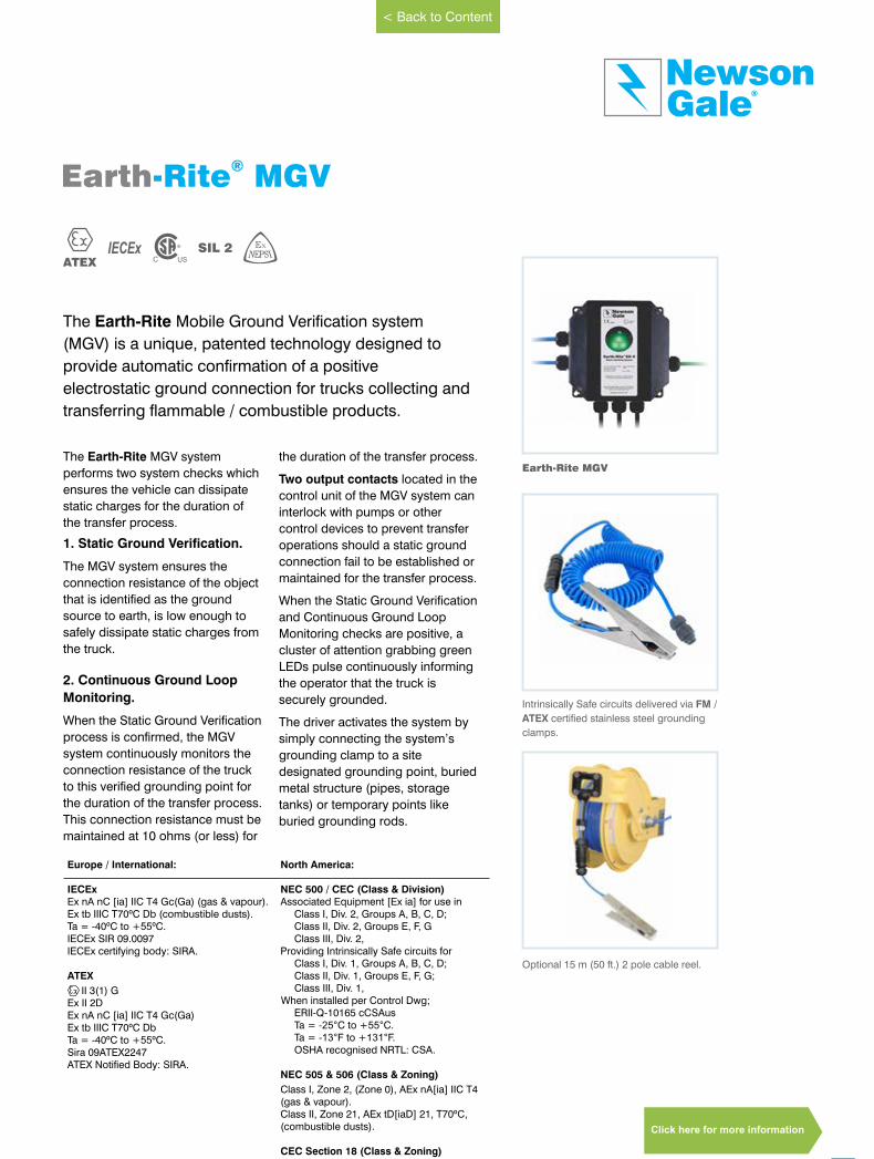
The Earth-Rite Mobile Ground Verification system
(MGV) is a unique, patented technology designed to
provide automatic confirmation of a positive
electrostatic ground connection for trucks collecting and
transferring flammable / combustible products.
The Earth-Rite MGV system
performs two system checks which
ensures the vehicle can dissipate
static charges for the duration of
the transfer process.
1. Static Ground Verification.
The MGV system ensures the
connection resistance of the object
that is identified as the ground
source to earth, is low enough to
safely dissipate static charges from
the truck.
2. Continuous Ground Loop
Monitoring.
When the Static Ground Verification
process is confirmed, the MGV
system continuously monitors the
connection resistance of the truck
to this verified grounding point for
the duration of the transfer process.
This connection resistance must be
maintained at 10 ohms (or less) for
the duration of the transfer process.
Two output contacts located in the
control unit of the MGV system can
interlock with pumps or other
control devices to prevent transfer
operations should a static ground
connection fail to be established or
maintained for the transfer process.
When the Static Ground Verification
and Continuous Ground Loop
Monitoring checks are positive, a
cluster of attention grabbing green
LEDs pulse continuously informing
the operator that the truck is
securely grounded.
The driver activates the system by
simply connecting the system’s
grounding clamp to a site
designated grounding point, buried
metal structure (pipes, storage
tanks) or temporary points like
buried grounding rods.
IECEx SIL 2ATEX
Earth-Rite MGV®
Earth-Rite MGV
Intrinsically Safe circuits delivered via FM /
ATEX certified stainless steel grounding
clamps.
Optional 15 m (50 ft.) 2 pole cable reel.
www.newson-gale.co.uk
Europe / International: North America:
IECExEx nA nC [ia] IIC T4 Gc(Ga) (gas & vapour).Ex tb IIIC T70ºC Db (combustible dusts).Ta = -40ºC to +55ºC.IECEx SIR 09.0097IECEx certifying body: SIRA.
ATEX
II 3(1) GEx II 2DEx nA nC [ia] IIC T4 Gc(Ga)Ex tb IIIC T70ºC Db Ta = -40ºC to +55ºC.Sira 09ATEX2247ATEX Notified Body: SIRA.
NEC 500 / CEC (Class & Division)Associated Equipment [Ex ia] for use in
Class I, Div. 2, Groups A, B, C, D;Class II, Div. 2, Groups E, F, GClass III, Div. 2,
Providing Intrinsically Safe circuits forClass I, Div. 1, Groups A, B, C, D;Class II, Div. 1, Groups E, F, G;Class III, Div. 1,
When installed per Control Dwg;ERII-Q-10165 cCSAusTa = -25°C to +55°C.Ta = -13°F to +131°F.OSHA recognised NRTL: CSA.
NEC 505 & 506 (Class & Zoning)
Class I, Zone 2, (Zone 0), AEx nA[ia] IIC T4(gas & vapour).Class II, Zone 21, AEx tD[iaD] 21, T70ºC, (combustible dusts).
CEC Section 18 (Class & Zoning)
Class I, Zone 2 (Zone 0) Ex nA[ia] IIC T4DIP A21, IP66, T70ºC
< Back to Content
Click here for more information

12
Leading the way in hazardous area static control
Conductive metal objects like railcars, LACT units, skids
and IBCs that come into contact with electrostatically
charged liquids can accumulate hazardous levels of
electrostatic charge that could discharge static sparks
with energies far in excess of the minimum ignition
energies of a vast range of combustible gases and
vapours.
If an ungrounded object is allowed
to accumulate electrostatic
charges, the voltage present on the
object rises dramatically in a very
short space of time. Because the
object is at a high voltage, it is
seeking to find ways of discharging
this excess energy and the most
efficient way of doing this is to
discharge the excess charge in the
form of a spark.
Grounded objects that are in close
proximity to charged objects are
good targets for electrostatic
discharges. Permitting the
uncontrolled accumulation of static
electricity in an EX / HAZLOC
atmosphere is no different to having
an engine’s spark plug exposed to
a potentially flammable
atmosphere.
If the transfer system is not
grounded, the electrostatic voltage
of objects like railcars can build up
to hazardous levels in less than
20 seconds.
A grounding system that combines
a simple visual “GO / NO GO”
communication via indicators with
interlock control capability is the
most effective means of controlling
the risk of ignitions caused by static
electricity during operations
involving railcars, IBCs and drums.
Interlocking the transfer system with
the grounding system is probably
the ultimate layer of protection
equipment specifiers and designers
can take to ensure the equipment
is grounded.
Grounding railcars, IBC’s and drums with system interlocks and indication
IEC 60079-32-1, 13.3.1.4
“Movable metal items” states:
Where such situations are expected, the object
should be earthed by an alternative means (e.g.
earthing cable). A connection resistance of 10 Ω between the cable and the item to be earthed is recommended. Earthing and bonding need to be
continuous during the period that charge build-
up could occur and cause electrostatic hazards.
NFPA 77, 12.4.1 & 12.4.2.
“Railroad Tank Cars” states:
In general, the precautions for railroad tank cars
are similar to those for tank vehicles specified in
Section 12.2*.
Many tank cars are equipped with non
conductive bearings and nonconductive wear
pads located between the car itself and the trucks
(wheel assemblies). Consequently, resistance to
ground through the rails might not be low
enough to prevent accumulation of a static
charge on the tank car body. Therefore, bonding
of the tank car body to the fill system piping is
necessary to protect against charge
accumulation.
*Section 12.2:
Tank trucks should be bonded to the fill system,
and all bonding and grounding should be in
place prior to starting operations. Ground
indicators, often interlocked with the filling
system, frequently are used to ensure bonding is
in place.
www.newson-gale.co.uk
< Back to Content
13
GaleNewson
®
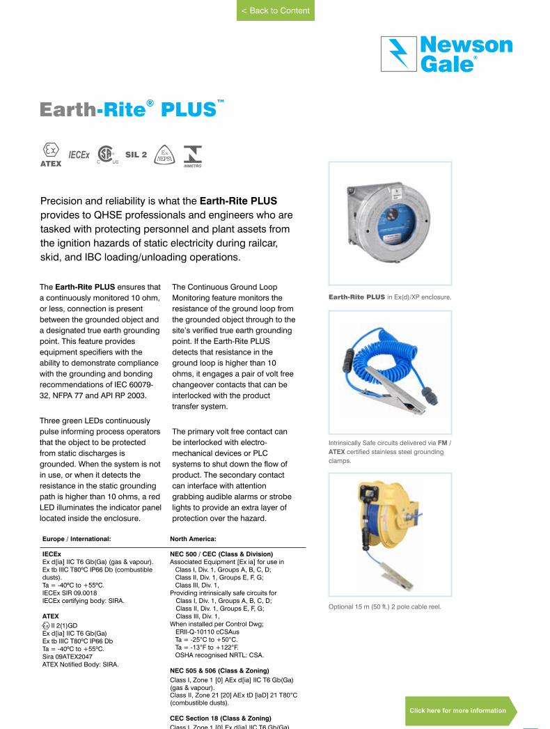
Precision and reliability is what the Earth-Rite PLUS
provides to QHSE professionals and engineers who are
tasked with protecting personnel and plant assets from
the ignition hazards of static electricity during railcar,
skid, and IBC loading/unloading operations.
IECEx SIL 2ATEX
Earth ™-Rite PLUS®
Earth-Rite PLUS in Ex(d)/XP enclosure.
The Earth-Rite PLUS ensures that
a continuously monitored 10 ohm,
or less, connection is present
between the grounded object and
a designated true earth grounding
point. This feature provides
equipment specifiers with the
ability to demonstrate compliance
with the grounding and bonding
recommendations of IEC 60079-
32, NFPA 77 and API RP 2003.
Three green LEDs continuously
pulse informing process operators
that the object to be protected
from static discharges is
grounded. When the system is not
in use, or when it detects the
resistance in the static grounding
path is higher than 10 ohms, a red
LED illuminates the indicator panel
located inside the enclosure.
The Continuous Ground Loop
Monitoring feature monitors the
resistance of the ground loop from
the grounded object through to the
site’s verified true earth grounding
point. If the Earth-Rite PLUS
detects that resistance in the
ground loop is higher than 10
ohms, it engages a pair of volt free
changeover contacts that can be
interlocked with the product
transfer system.
The primary volt free contact can
be interlocked with electro-
mechanical devices or PLC
systems to shut down the flow of
product. The secondary contact
can interface with attention
grabbing audible alarms or strobe
lights to provide an extra layer of
protection over the hazard.
Intrinsically Safe circuits delivered via FM /
ATEX certified stainless steel grounding
clamps.
Optional 15 m (50 ft.) 2 pole cable reel.
www.newson-gale.co.uk
Europe / International: North America:
IECExEx d[ia] IIC T6 Gb(Ga) (gas & vapour).Ex tb IIIC T80ºC IP66 Db (combustible dusts).Ta = -40ºC to +55ºC.IECEx SIR 09.0018IECEx certifying body: SIRA.
ATEX
II 2(1)GDEx d[ia] IIC T6 Gb(Ga) Ex tb IIIC T80ºC IP66 Db Ta = -40ºC to +55ºC.Sira 09ATEX2047ATEX Notified Body: SIRA.
NEC 500 / CEC (Class & Division)Associated Equipment [Ex ia] for use in
Class I, Div. 1, Groups A, B, C, D;Class II, Div. 1, Groups E, F, G;Class III, Div. 1,
Providing intrinsically safe circuits forClass I, Div. 1, Groups A, B, C, D;Class II, Div. 1, Groups E, F, G;Class III, Div. 1,
When installed per Control Dwg;ERII-Q-10110 cCSAusTa = -25°C to +50°C.Ta = -13°F to +122°F.OSHA recognised NRTL: CSA.
NEC 505 & 506 (Class & Zoning)
Class I, Zone 1 [0] AEx d[ia] IIC T6 Gb(Ga) (gas & vapour).Class II, Zone 21 [20] AEx tD [iaD] 21 T80°C (combustible dusts).
CEC Section 18 (Class & Zoning)
Class I, Zone 1 [0] Ex d[ia] IIC T6 Gb(Ga)DIP A21, IP66, T80ºC
< Back to Content
Click here for more information
www.newson-gale.comIssue 8 Issue 8
14
Leading the way in hazardous area static control
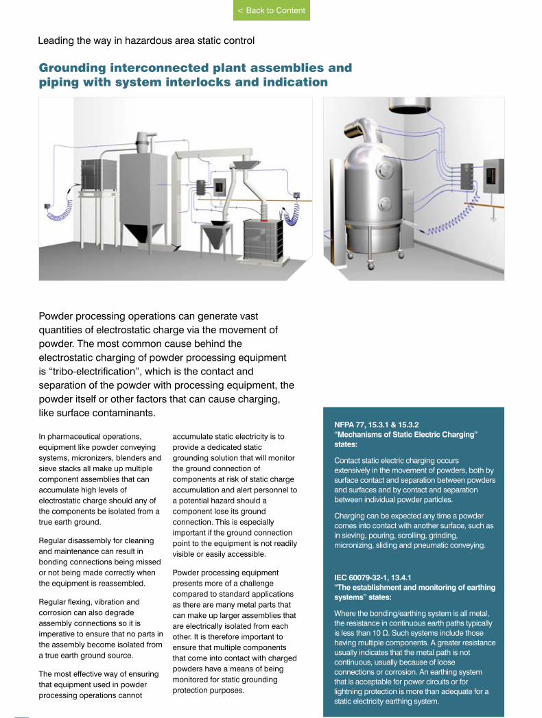
Powder processing operations can generate vast
quantities of electrostatic charge via the movement of
powder. The most common cause behind the
electrostatic charging of powder processing equipment
is “tribo-electrification”, which is the contact and
separation of the powder with processing equipment, the
powder itself or other factors that can cause charging,
like surface contaminants.
In pharmaceutical operations,
equipment like powder conveying
systems, micronizers, blenders and
sieve stacks all make up multiple
component assemblies that can
accumulate high levels of
electrostatic charge should any of
the components be isolated from a
true earth ground.
Regular disassembly for cleaning
and maintenance can result in
bonding connections being missed
or not being made correctly when
the equipment is reassembled.
Regular flexing, vibration and
corrosion can also degrade
assembly connections so it is
imperative to ensure that no parts in
the assembly become isolated from
a true earth ground source.
The most effective way of ensuring
that equipment used in powder
processing operations cannot
accumulate static electricity is to
provide a dedicated static
grounding solution that will monitor
the ground connection of
components at risk of static charge
accumulation and alert personnel to
a potential hazard should a
component lose its ground
connection. This is especially
important if the ground connection
point to the equipment is not readily
visible or easily accessible.
Powder processing equipment
presents more of a challenge
compared to standard applications
as there are many metal parts that
can make up larger assemblies that
are electrically isolated from each
other. It is therefore important to
ensure that multiple components
that come into contact with charged
powders have a means of being
monitored for static grounding
protection purposes.
Grounding interconnected plant assemblies andpiping with system interlocks and indication
NFPA 77, 15.3.1 & 15.3.2
“Mechanisms of Static Electric Charging”
states:
Contact static electric charging occurs
extensively in the movement of powders, both by
surface contact and separation between powders
and surfaces and by contact and separation
between individual powder particles.
Charging can be expected any time a powder
comes into contact with another surface, such as
in sieving, pouring, scrolling, grinding,
micronizing, sliding and pneumatic conveying.
IEC 60079-32-1, 13.4.1
“The establishment and monitoring of earthing
systems” states:
Where the bonding/earthing system is all metal,
the resistance in continuous earth paths typically
is less than 10 Ω. Such systems include those
having multiple components. A greater resistance
usually indicates that the metal path is not
continuous, usually because of loose
connections or corrosion. An earthing system
that is acceptable for power circuits or for
lightning protection is more than adequate for a
static electricity earthing system.
www.newson-gale.co.uk
< Back to Content
15
GaleNewson
®
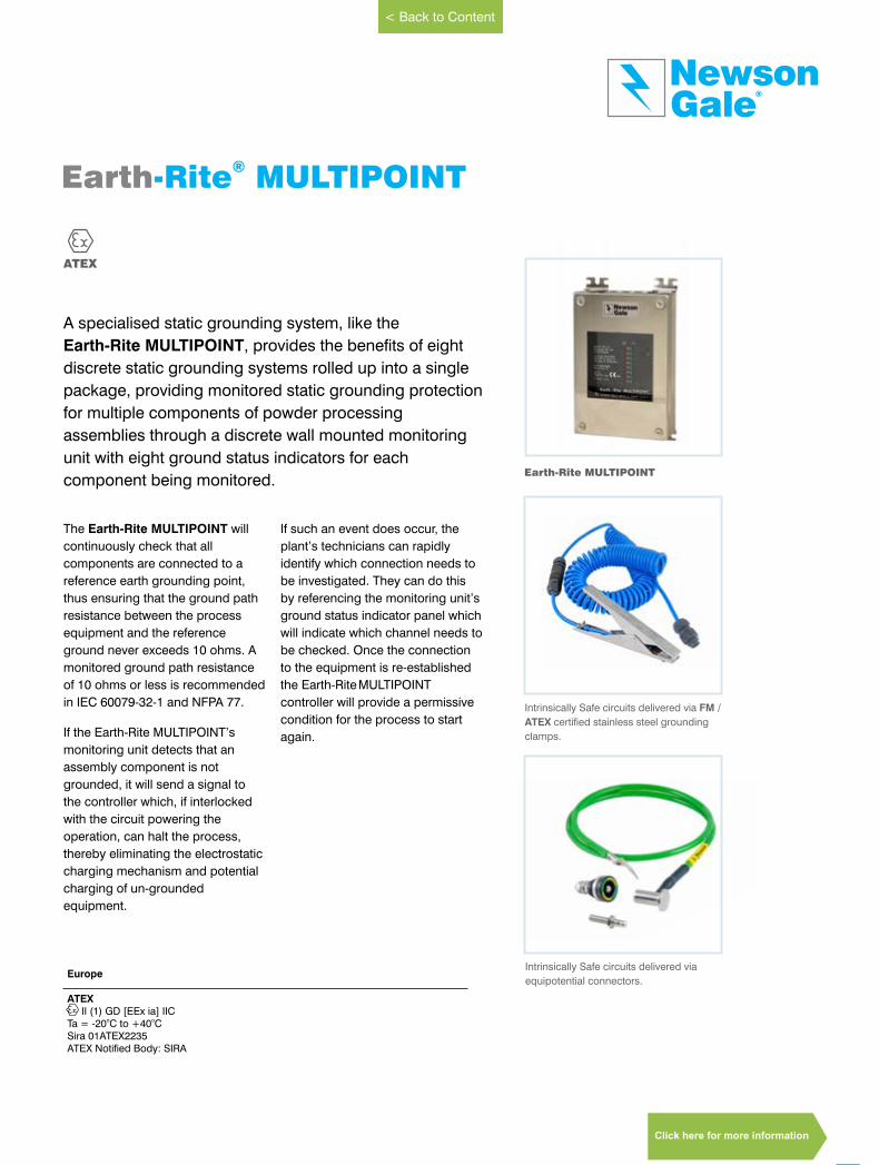
A specialised static grounding system, like the
Earth-Rite MULTIPOINT, provides the benefits of eight
discrete static grounding systems rolled up into a single
package, providing monitored static grounding protection
for multiple components of powder processing
assemblies through a discrete wall mounted monitoring
unit with eight ground status indicators for each
component being monitored.
The Earth-Rite MULTIPOINT will
continuously check that all
components are connected to a
reference earth grounding point,
thus ensuring that the ground path
resistance between the process
equipment and the reference
ground never exceeds 10 ohms. A
monitored ground path resistance
of 10 ohms or less is recommended
in IEC 60079-32-1 and NFPA 77.
If the Earth-Rite MULTIPOINT’s
monitoring unit detects that an
assembly component is not
grounded, it will send a signal to
the controller which, if interlocked
with the circuit powering the
operation, can halt the process,
thereby eliminating the electrostatic
charging mechanism and potential
charging of un-grounded
equipment.
If such an event does occur, the
plant’s technicians can rapidly
identify which connection needs to
be investigated. They can do this
by referencing the monitoring unit’s
ground status indicator panel which
will indicate which channel needs to
be checked. Once the connection
to the equipment is re-established the Earth-RiteMULTIPOINT
controller will provide a permissive
condition for the process to start
again.
ATEX
Earth-Rite MULTIPOINT®
Earth-Rite MULTIPOINT
Europe
ATEX II (1) GD [EEx ia] IIC
o oTa = -20 C to +40 CSira 01ATEX2235ATEX Notified Body: SIRA
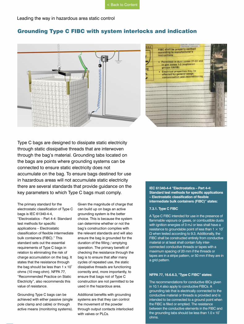
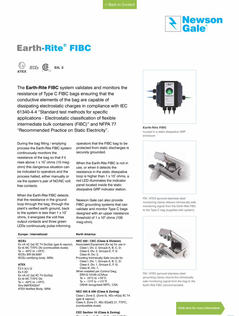
Intrinsically Safe circuits delivered via
equipotential connectors.
Intrinsically Safe circuits delivered via FM /
ATEX certified stainless steel grounding
clamps.
www.newson-gale.co.uk
< Back to Content
Click here for more information
16
Leading the way in hazardous area static control
Type C bags are designed to dissipate static electricity
through static dissipative threads that are interwoven
through the bag’s material. Grounding tabs located on
the bags are points where grounding systems can be
connected to ensure static electricity does not
accumulate on the bag. To ensure bags destined for use
in hazardous areas will not accumulate static electricity
there are several standards that provide guidance on the
key parameters to which Type C bags must comply.
The primary standard for the
electrostatic classification of Type C
bags is IEC 61340-4-4,
“Electrostatics – Part 4-4: Standard
test methods for specific
applications – Electrostatic
classification of flexible intermediate
bulk containers (FIBC).” This
standard sets out the essential
requirements of Type C bags in
relation to eliminating the risk of
charge accumulation on the bag. It
states that the resistance through 7the bag should be less than 1 x 10
ohms (10 meg-ohm). NFPA 77,
“Recommended Practice on Static
Electricity”, also recommends this
value of resistance.
Grounding Type C bags can be
achieved with either passive (single
pole clamp and cable) or through
active means (monitoring systems).
Given the magnitude of charge that
can build up on bags an active
grounding system is the better
choice. This is because the system
can determine whether or not the
bag’s construction complies with
the relevant standards and will also
ensure the bag is grounded for the
duration of the filling / emptying
operation. The primary benefit of
checking the resistance through the
bag is to ensure that after many
cycles of repeated use, the static
dissipative threads are functioning
correctly and, more importantly, to
ensure that bags not of Type C
construction are not permitted to be
used in the hazardous area.
Additional benefits with grounding
systems are that they can control
the movement of the powder
through output contacts interlocked
with valves or PLCs.
Grounding Type C FIBC with system interlocks and indication
IEC 61340-4-4 “Electrostatics – Part 4-4:
Standard test methods for specific applications
– Electrostatic classification of flexible
intermediate bulk containers (FIBC)” states:
7.3.1. Type C FIBC
A Type C FIBC intended for use in the presence of
flammable vapours or gases, or combustible dusts
with ignition energies of 3 mJ or less shall have a 7resistance to groundable point of less than 1 × 10
Ω when tested according to 9.3. Additionally, the
FIBC shall be constructed entirely from conductive
material or at least shall contain fully inter-
connected conductive threads or tapes with a
maximum spacing of 20 mm if the threads or
tapes are in a stripe pattern, or 50 mm if they are in
a grid pattern.
NFPA 77, 16.6.6.3, “Type C FIBC” states:
The recommendations for conductive IBCs given
in 10.1.4 also apply to conductive FIBCs. A
grounding tab that is electrically connected to the
conductive material or threads is provided and is
intended to be connected to a ground point when
the FIBC is filled or emptied. The resistance
between the conductive elements in the FIBC and 7the grounding tabs should be less than 1.0 x 10
ohms.
www.newson-gale.co.uk
< Back to Content
During the bag filling / emptying
process the Earth-Rite FIBC system
continuously monitors the
resistance of the bag so that if it 7rises above 1 x 10 ohms (10 meg-
ohm) this dangerous situation can
be indicated to operators and the
process halted, either manually or
via the system’s pair of NO/NC volt
free contacts.
When the Earth-Rite FIBC detects
that the resistance in the ground
loop through the bag, through the
plant’s verified earth ground, back 7to the system is less than 1 x 10
ohms, it energises the volt free
output contacts and three green
LEDs continuously pulse informing
operators that the FIBC bag to be
protected from static discharges is
securely grounded.
When the Earth-Rite FIBC is not in
use, or when it detects the
resistance in the static dissipative 7loop is higher than 1 x 10 ohms, a
red LED illuminates the indicator
panel located inside the static
dissipative GRP indicator station.
Newson Gale can also provide
FIBC grounding systems that can
validate and monitor Type C bags
designed with an upper resistance 8threshold of 1 x 10 ohms (100
meg-ohm).
FM / ATEX aproved stainless steel
grounding clamp returns the intrinsically
safe monitoring signal from the bag to the
Earth-Rite FIBC (recommended).
17
GaleNewson
®
The Earth-Rite FIBC system validates and monitors the
resistance of Type C FIBC bags ensuring that the
conductive elements of the bag are capable of
dissipating electrostatic charges in compliance with IEC
61340-4-4 “Standard test methods for specific
applications - Electrostatic classification of flexible
intermediate bulk containers (FIBC)” and NFPA 77
“Recommended Practice on Static Electricity”.
IECEx SIL 2ATEX
Earth-Rite FIBC®
Earth-Rite FIBC housed in a static dissipative GRP
enclosure
FM / ATEX aproved stainless steel
monitoring clamp delivers intrinsically safe
monitoring signal from the Earth-Rite FIBC
to the Type C bag (supplied with system).
www.newson-gale.co.uk
Europe / International: North America:
IECExEx nA nC [ia] IIC T4 Gc(Ga) (gas & vapour).Ex tb IIIC T70ºC Db (combustible dusts).Ta = -40ºC to +55ºC.IECEx SIR 09.0097IECEx certifying body: SIRA.
ATEX
II 3(1) GEx II 2DEx nA nC [ia] IIC T4 Gc(Ga)Ex tb IIIC T70ºC Db Ta = -40ºC to +55ºC.Sira 09ATEX2247ATEX Notified Body: SIRA.
NEC 500 / CEC (Class & Division)Associated Equipment [Ex ia] for use in
Class I, Div. 2, Groups A, B, C, D;Class II, Div. 2, Groups E, F, GClass III, Div. 2,
Providing Intrinsically Safe circuits forClass I, Div. 1, Groups A, B, C, D;Class II, Div. 1, Groups E, F, G;Class III, Div. 1,
When installed per Control Dwg;ERII-Q-10165 cCSAusTa = -25°C to +55°C.Ta = -13°F to +131°F.OSHA recognised NRTL: CSA.
NEC 505 & 506 (Class & Zoning)
Class I, Zone 2, (Zone 0), AEx nA[ia] IIC T4(gas & vapour).Class II, Zone 21, AEx tD[iaD] 21, T70ºC, (combustible dusts).
CEC Section 18 (Class & Zoning)
Class I, Zone 2 (Zone 0) Ex nA[ia] IIC T4DIP A21, IP66, T70ºC
< Back to Content
Click here for more information

www.newson-gale.comIssue 8 Issue 8
18
Leading the way in hazardous area static control
In limited circumstances electrical contractors may need to provide
a static grounding solution as part of a specialised
instrumentation/automation project. To satisfy the requirements of
bespoke projects designers are often limited by standard “off-the-
shelf” static grounding solutions that cannot be customised to
provide a good “fit” for their specific application design
requirements. A suitable design trade-off is to specify static
grounding relays that can monitor a range of resistance values.
Although installations of this type are
limited by not having ground status
indication provided at the point of
grounding, the normal application for
such relays is to monitor the ground
status of permanent fixed equipment
connections or rotating machinery and
using an internal relay to provide outputs
to PLCs or customised HMI panels.
Ensuring that a rotating drum or impeller
is correctly grounded to 10 ohms can be
difficult as it is not always possible to rely
on a consistent and smooth connection
between the rotating shaft and the chassis
of the machine.
Due to the design of bearings, etc. a good
method of guaranteeing ground continuity
is to use a non-hazardous area mounted
ground monitoring relay to test the
ground connection to the drum or
impeller via a pair of carbon brushes or a
slip ring, acting on the shaft.
Such relays may also be used to test the
ground connection to key items of fixed
plants, such as large storage vessels for
flammable liquids.
Relays that have a range of resistance
settings, like the Earth-Rite OMEGA II are
normally mounted on DIN rails inside
electrical panels installed in non-
hazardous areas.
Panel mounted grounding with system interlocks
www.newson-gale.co.uk
< Back to Content
North America:
NEC 500 / CEC (Class & Division)
Intrinsically safe associated apparatusfor supply to locations classified:
Class I, Div. 1, Groups A, B, C, D.
Class II, Div. 1, Groups E, F, G.
Class III, Div. 1.
Ta = -40°C to +60°C.
Ta = -40°F to +140°F
OSHA recognised NRTL: CSA.
NEC 505 & 506 (Class & Zoning)
Class I, Zone 0, [AEx ia], IIC (gas & vapour).Class II, Zone 20, [AEx iaD], IIIC (combustible dusts).
CEC Section 18 (Class & Zoning)
[Ex ia] IIC
Europe / International:
IECEx
[Ex ia Ga] IIC (gas & vapour).[Ex ia Da] IIIC (combustible dusts).Ta = -40ºC to +60ºC.IECEx SIR 13.0003XIECEx certifying body: SIRA.
ATEX
II (1)GD[Ex ia Ga] IIC (gas & vapour).[Ex ia Da] IIIC (combustible dusts).Ta = -40ºC to +60ºC.Sira 13ATEX2009XATEX Notified Body: SIRA.
19
GaleNewson
®
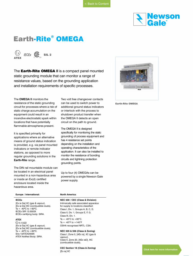
The Earth-Rite OMEGA II is a compact panel mounted
static grounding module that can monitor a range of
resistance values, based on the grounding application
and installation requirements of specific processes.
IECEx SIL 2ATEX
Earth-Rite OMEGA®
Earth-Rite OMEGA
The OMEGA II monitors the
resistance of the static grounding
circuit for processes where a risk of
static charge accumulation on the
equipment could result in an
incendive electrostatic spark within
locations that have potentially
flammable atmospheres present.
It is specified primarily for
applications where an alternative
means of ground status indication
is provided, e.g. via panel mounted
indicators or remote indicator
stations, as opposed to more
regular grounding solutions in the
Earth-Rite range.
The DIN rail mountable module can
be located in an electrical panel
mounted in a non-hazardous area
or inside an Ex(d) certified
enclosure located inside the
hazardous area.
Two volt free changeover contacts
can be used to switch power to
additional ground status indicators
or interlock with the process to
shutdown product transfer when
the OMEGA II detects an open
circuit on the path to ground.
The OMEGA II is designed
specifically for monitoring the static
grounding of process equipment and
has 4 resistance set points
depending on the installation and
operating characteristics of the
application. It can also be installed to
monitor the resistance of bonding
circuits and lightning protection
grounding points.
Up to four (4) OMEGAs can be
powered by a single Newson Gale
power supply.
www.newson-gale.co.uk
< Back to Content
Click here for more information
20
Leading the way in hazardous area static control
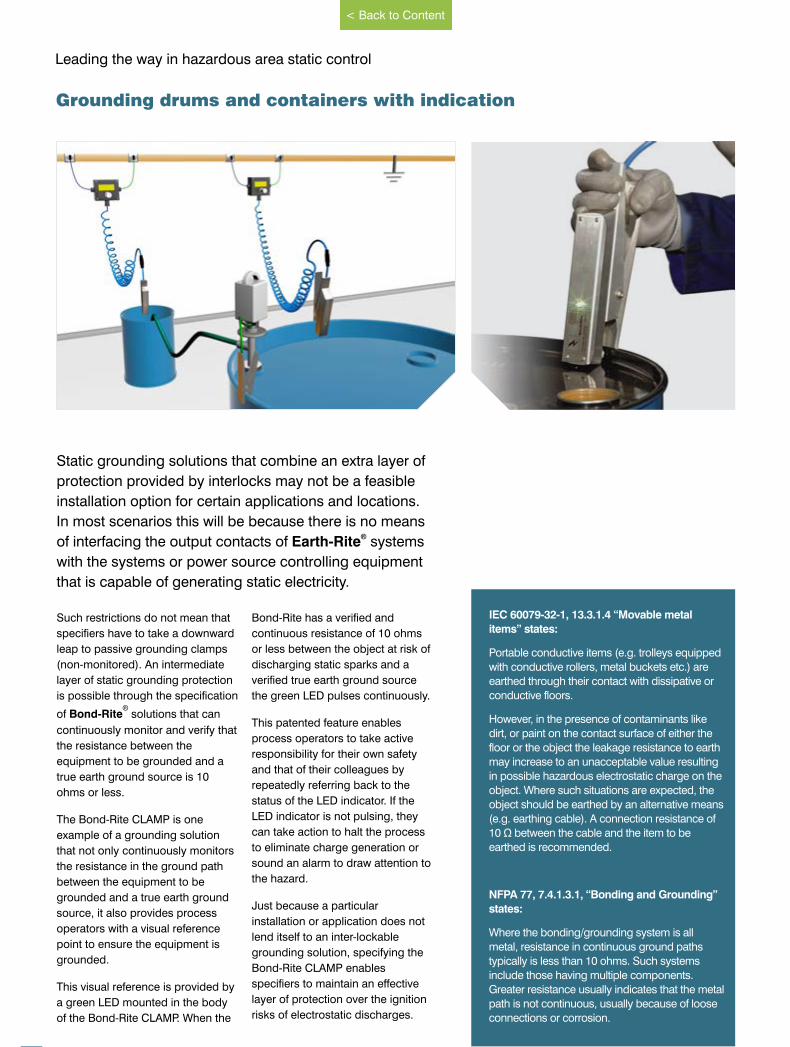
Static grounding solutions that combine an extra layer of
protection provided by interlocks may not be a feasible
installation option for certain applications and locations.
In most scenarios this will be because there is no means ®of interfacing the output contacts of Earth-Rite systems
with the systems or power source controlling equipment
that is capable of generating static electricity.
Such restrictions do not mean that
specifiers have to take a downward
leap to passive grounding clamps
(non-monitored). An intermediate
layer of static grounding protection
is possible through the specification ®
of Bond-Rite solutions that can
continuously monitor and verify that
the resistance between the
equipment to be grounded and a
true earth ground source is 10
ohms or less.
The Bond-Rite CLAMP is one
example of a grounding solution
that not only continuously monitors
the resistance in the ground path
between the equipment to be
grounded and a true earth ground
source, it also provides process
operators with a visual reference
point to ensure the equipment is
grounded.
This visual reference is provided by
a green LED mounted in the body
of the Bond-Rite CLAMP. When the
Bond-Rite has a verified and
continuous resistance of 10 ohms
or less between the object at risk of
discharging static sparks and a
verified true earth ground source
the green LED pulses continuously.
This patented feature enables
process operators to take active
responsibility for their own safety
and that of their colleagues by
repeatedly referring back to the
status of the LED indicator. If the
LED indicator is not pulsing, they
can take action to halt the process
to eliminate charge generation or
sound an alarm to draw attention to
the hazard.
Just because a particular
installation or application does not
lend itself to an inter-lockable
grounding solution, specifying the
Bond-Rite CLAMP enables
specifiers to maintain an effective
layer of protection over the ignition
risks of electrostatic discharges.
Grounding drums and containers with indication
IEC 60079-32-1, 13.3.1.4 “Movable metal
items” states:
Portable conductive items (e.g. trolleys equipped
with conductive rollers, metal buckets etc.) are
earthed through their contact with dissipative or
conductive floors.
However, in the presence of contaminants like
dirt, or paint on the contact surface of either the
floor or the object the leakage resistance to earth
may increase to an unacceptable value resulting
in possible hazardous electrostatic charge on the
object. Where such situations are expected, the
object should be earthed by an alternative means
(e.g. earthing cable). A connection resistance of
10 Ω between the cable and the item to be
earthed is recommended.
NFPA 77, 7.4.1.3.1, “Bonding and Grounding”
states:
Where the bonding/grounding system is all
metal, resistance in continuous ground paths
typically is less than 10 ohms. Such systems
include those having multiple components.
Greater resistance usually indicates that the metal
path is not continuous, usually because of loose
connections or corrosion.
www.newson-gale.co.uk
< Back to Content
Equipment specifiers can order the Bond-
Rite CLAMP with 2-pole Cen-Stat cable on
standard spiral lengths of 3 m (10 ft.), 5 m
(16 ft.) and 10 m (32 ft.) of cable. All
cables supplied with universal quick
connects for easy connection.
21
GaleNewson
®
IECExATEX
Bond-Rite CLAMP®
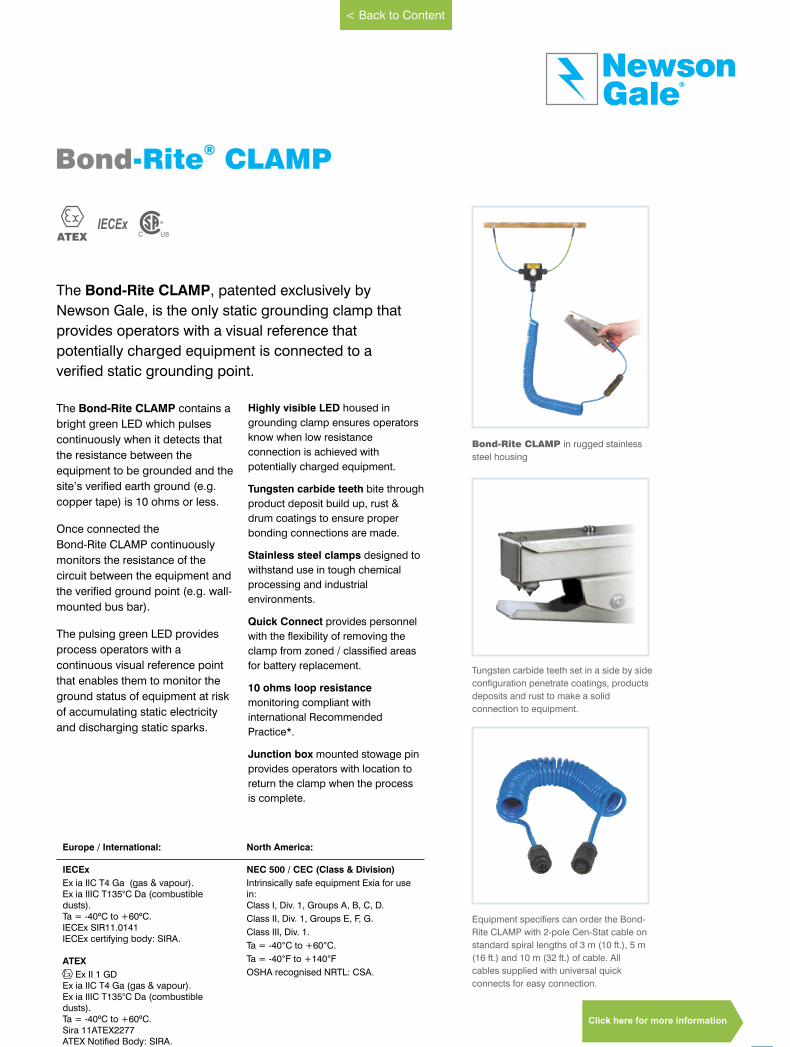
Bond-Rite CLAMP in rugged stainless
steel housing
Tungsten carbide teeth set in a side by side
configuration penetrate coatings, products
deposits and rust to make a solid
connection to equipment.
The Bond-Rite CLAMP contains a
bright green LED which pulses
continuously when it detects that
the resistance between the
equipment to be grounded and the
site’s verified earth ground (e.g.
copper tape) is 10 ohms or less.
Once connected the
Bond-Rite CLAMP continuously
monitors the resistance of the
circuit between the equipment and
the verified ground point (e.g. wall-
mounted bus bar).
The pulsing green LED provides
process operators with a
continuous visual reference point
that enables them to monitor the
ground status of equipment at risk
of accumulating static electricity
and discharging static sparks.
Highly visible LED housed in
grounding clamp ensures operators
know when low resistance
connection is achieved with
potentially charged equipment.
Tungsten carbide teeth bite through
product deposit build up, rust &
drum coatings to ensure proper
bonding connections are made.
Stainless steel clamps designed to
withstand use in tough chemical
processing and industrial
environments.
Quick Connect provides personnel
with the flexibility of removing the
clamp from zoned / classified areas
for battery replacement.
10 ohms loop resistance
monitoring compliant with
international Recommended
Practice*.
Junction box mounted stowage pin
provides operators with location to
return the clamp when the process
is complete.
The Bond-Rite CLAMP, patented exclusively by
Newson Gale, is the only static grounding clamp that
provides operators with a visual reference that
potentially charged equipment is connected to a
verified static grounding point.
North America:
NEC 500 / CEC (Class & Division)
Intrinsically safe equipment Exia for use in:Class I, Div. 1, Groups A, B, C, D.
Class II, Div. 1, Groups E, F, G.
Class III, Div. 1.
Ta = -40°C to +60°C.
Ta = -40°F to +140°F
OSHA recognised NRTL: CSA.
Europe / International:
IECEx
Ex ia IIC T4 Ga (gas & vapour).Ex ia IIIC T135°C Da (combustible dusts).Ta = -40ºC to +60ºC.IECEx SIR11.0141IECEx certifying body: SIRA.
ATEX
Ex II 1 GDEx ia IIC T4 Ga (gas & vapour).Ex ia IIIC T135°C Da (combustible dusts).Ta = -40ºC to +60ºC.Sira 11ATEX2277ATEX Notified Body: SIRA.
www.newson-gale.co.uk
< Back to Content
Click here for more information
22
Leading the way in hazardous area static control
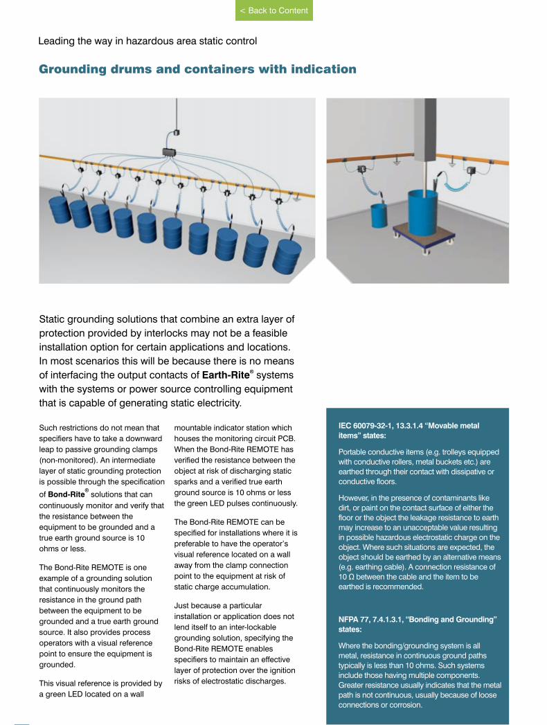
Static grounding solutions that combine an extra layer of
protection provided by interlocks may not be a feasible
installation option for certain applications and locations.
In most scenarios this will be because there is no means ®of interfacing the output contacts of Earth-Rite systems
with the systems or power source controlling equipment
that is capable of generating static electricity.
Such restrictions do not mean that
specifiers have to take a downward
leap to passive grounding clamps
(non-monitored). An intermediate
layer of static grounding protection
is possible through the specification ®
of Bond-Rite solutions that can
continuously monitor and verify that
the resistance between the
equipment to be grounded and a
true earth ground source is 10
ohms or less.
The Bond-Rite REMOTE is one
example of a grounding solution
that continuously monitors the
resistance in the ground path
between the equipment to be
grounded and a true earth ground
source. It also provides process
operators with a visual reference
point to ensure the equipment is
grounded.
This visual reference is provided by
a green LED located on a wall
mountable indicator station which
houses the monitoring circuit PCB.
When the Bond-Rite REMOTE has
verified the resistance between the
object at risk of discharging static
sparks and a verified true earth
ground source is 10 ohms or less
the green LED pulses continuously.
The Bond-Rite REMOTE can be
specified for installations where it is
preferable to have the operator’s
visual reference located on a wall
away from the clamp connection
point to the equipment at risk of
static charge accumulation.
Just because a particular
installation or application does not
lend itself to an inter-lockable
grounding solution, specifying the
Bond-Rite REMOTE enables
specifiers to maintain an effective
layer of protection over the ignition
risks of electrostatic discharges.
IEC 60079-32-1, 13.3.1.4 “Movable metal
items” states:
Portable conductive items (e.g. trolleys equipped
with conductive rollers, metal buckets etc.) are
earthed through their contact with dissipative or
conductive floors.
However, in the presence of contaminants like
dirt, or paint on the contact surface of either the
floor or the object the leakage resistance to earth
may increase to an unacceptable value resulting
in possible hazardous electrostatic charge on the
object. Where such situations are expected, the
object should be earthed by an alternative means
(e.g. earthing cable). A connection resistance of
10 Ω between the cable and the item to be
earthed is recommended.
NFPA 77, 7.4.1.3.1, “Bonding and Grounding”
states:
Where the bonding/grounding system is all
metal, resistance in continuous ground paths
typically is less than 10 ohms. Such systems
include those having multiple components.
Greater resistance usually indicates that the metal
path is not continuous, usually because of loose
connections or corrosion.
Grounding drums and containers with indication
www.newson-gale.co.uk
< Back to Content

23
GaleNewson
®
IECExATEX
Bond-Rite REMOTE®
Bond-Rite REMOTE in static
dissipative GRP enclosure.
Bond-Rite REMOTE EP external power
supply can power up to 10 indicator
stations.
The precision and reliability of the Bond-Rite REMOTE
provides enhanced safety and security by continuously
testing the connection of the clamp to the container or
other conductive item of plant in a complete loop made
through the designated grounding point.
Europe / International: North America:
IECExEx ia IIC T4 Ga (Gas & Vapour).Ex ta IIIC T135ºC Da (Combustible Dusts).Ta = -40ºC to +60ºC.IECEx SIR 09.0023XIECEx certifying body: SIRA.
ATEX
II 1 GDEx ia IIC T4 GaEx ta IIIC T135ºC Da Ta = -40ºC to +60ºC.Sira 09ATEX2158XATEX Notified Body: SIRA.
NEC 500 / CEC (Class & Division)Intrinsically safe equipment Exia for use in:Class I, Div. 1, Groups A, B, C, D.
Class II, Div. 1, Groups E, F, G.
Class III, Div. 1.
Ta = -40°C to +60°C.
Ta = -40°F to +140°F
BRR-Q-11185 cCSAus
OSHA recognised NRTL: CSA.
NEC 505 & 506 (Class & Zoning)
Class I, Zone 0, AEx ia IIC T4 Ga(Gas & Vapour).Class II, Zone 20, AEx iaD 20 T135ºC, (Combustible Dusts).
CEC Section 18 (Class & Zoning)
Class I, Zone 0, Ex ia IIC T4 GaDIP A20, IP66, T135ºC
The Bond-Rite REMOTE delivers
a continuously monitored circuit
between grounded equipment and
verified ground points (e.g. wall-
mounted bus bar).
The pulsing green LED provides
process operators with a
continuous visual reference point
that enables them to monitor the
ground status of equipment at risk
of accumulating static electricity
and discharging static sparks.
The standard GRP enclosure is
static dissipative and suitable for
general processing environments.
The stainless steel enclosure
(SS 316) is designed to cater for
hygienic or corrosive
environment specifications.
Both enclosures provide a
minimum IP 65 degree of ingress
protection and are suitable for
both indoor and outdoor
installation.
The Bond-Rite REMOTE can be
powered with an intrinsically safe
9V battery (included). The
Bond-Rite REMOTE EP utilises an
external 230/115 V AC power
supply which can power up to 10
individual indicator stations.
The flexible external power supply
can be located in both the
‘hazardous’ (Zone 2/22 - Div.2) and
‘non-hazardous’ areas, with the
indicator stations mounted in the
zoned / HAZLOC area (Zone 0 /
Div.1) or lower.
Bond-Rite REMOTE in stainless steel
enclosure.
www.newson-gale.co.uk
Click here for more information
< Back to Content
www.newson-gale.comIssue 8
24
Leading the way in hazardous area static control
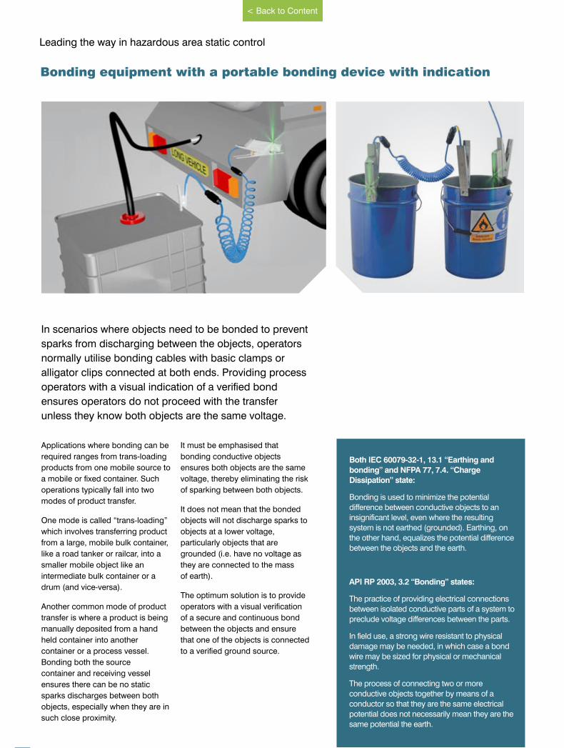
In scenarios where objects need to be bonded to prevent
sparks from discharging between the objects, operators
normally utilise bonding cables with basic clamps or
alligator clips connected at both ends. Providing process
operators with a visual indication of a verified bond
ensures operators do not proceed with the transfer
unless they know both objects are the same voltage.
Applications where bonding can be
required ranges from trans-loading
products from one mobile source to
a mobile or fixed container. Such
operations typically fall into two
modes of product transfer.
One mode is called “trans-loading”
which involves transferring product
from a large, mobile bulk container,
like a road tanker or railcar, into a
smaller mobile object like an
intermediate bulk container or a
drum (and vice-versa).
Another common mode of product
transfer is where a product is being
manually deposited from a hand
held container into another
container or a process vessel.
Bonding both the source
container and receiving vessel
ensures there can be no static
sparks discharges between both
objects, especially when they are in
such close proximity.
It must be emphasised that
bonding conductive objects
ensures both objects are the same
voltage, thereby eliminating the risk
of sparking between both objects.
It does not mean that the bonded
objects will not discharge sparks to
objects at a lower voltage,
particularly objects that are
grounded (i.e. have no voltage as
they are connected to the mass
of earth).
The optimum solution is to provide
operators with a visual verification
of a secure and continuous bond
between the objects and ensure
that one of the objects is connected
to a verified ground source.
Bonding equipment with a portable bonding device with indication
Both IEC 60079-32-1, 13.1 “Earthing and
bonding” and NFPA 77, 7.4. “Charge
Dissipation” state:
Bonding is used to minimize the potential
difference between conductive objects to an
insignificant level, even where the resulting
system is not earthed (grounded). Earthing, on
the other hand, equalizes the potential difference
between the objects and the earth.
API RP 2003, 3.2 “Bonding” states:
The practice of providing electrical connections
between isolated conductive parts of a system to
preclude voltage differences between the parts.
In field use, a strong wire resistant to physical
damage may be needed, in which case a bond
wire may be sized for physical or mechanical
strength.
The process of connecting two or more
conductive objects together by means of a
conductor so that they are the same electrical
potential does not necessarily mean they are the
same potential the earth.
www.newson-gale.co.uk
< Back to Content
IECExATEX
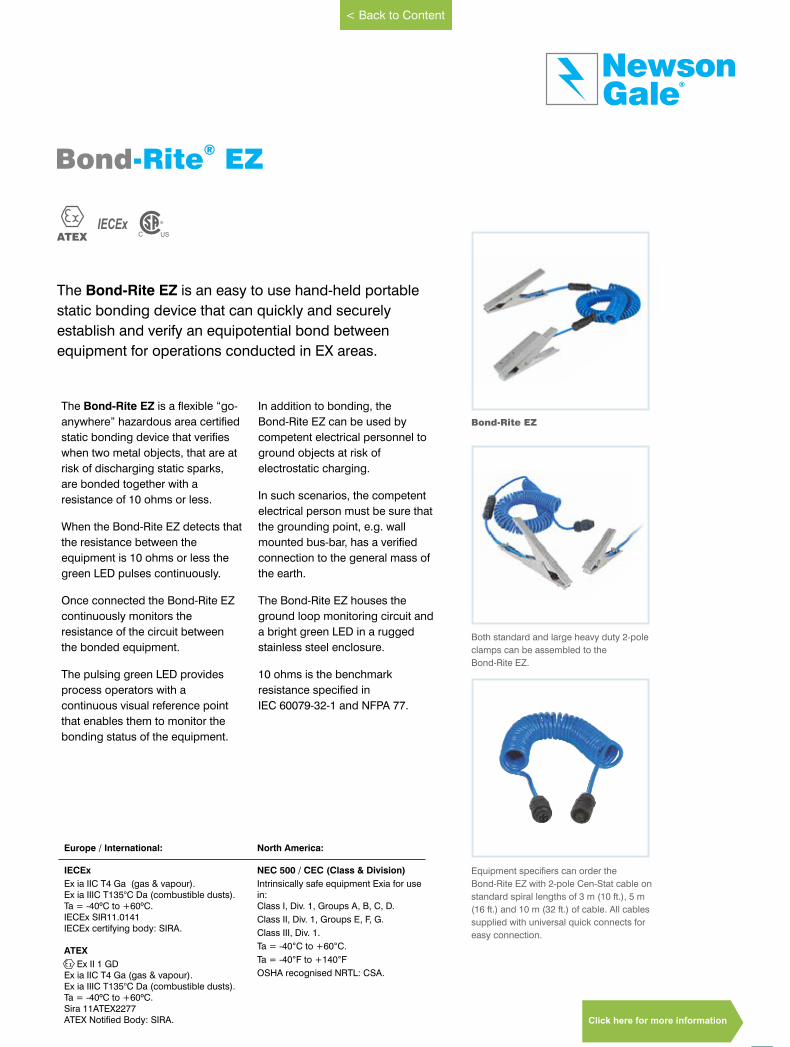
The Bond-Rite EZ is a flexible “go-
anywhere” hazardous area certified
static bonding device that verifies
when two metal objects, that are at
risk of discharging static sparks,
are bonded together with a
resistance of 10 ohms or less.
When the Bond-Rite EZ detects that
the resistance between the
equipment is 10 ohms or less the
green LED pulses continuously.
Once connected the Bond-Rite EZ
continuously monitors the
resistance of the circuit between
the bonded equipment.
The pulsing green LED provides
process operators with a
continuous visual reference point
that enables them to monitor the
bonding status of the equipment.
In addition to bonding, the
Bond-Rite EZ can be used by
competent electrical personnel to
ground objects at risk of
electrostatic charging.
In such scenarios, the competent
electrical person must be sure that
the grounding point, e.g. wall
mounted bus-bar, has a verified
connection to the general mass of
the earth.
The Bond-Rite EZ houses the
ground loop monitoring circuit and
a bright green LED in a rugged
stainless steel enclosure. 10 ohms is the benchmark
resistance specified in
IEC 60079-32-1 and NFPA 77.
25
GaleNewson
®
The Bond-Rite EZ is an easy to use hand-held portable
static bonding device that can quickly and securely
establish and verify an equipotential bond between
equipment for operations conducted in EX areas.
Bond-Rite EZ®
Bond-Rite EZ
Both standard and large heavy duty 2-pole
clamps can be assembled to the
Bond-Rite EZ.
Equipment specifiers can order the
Bond-Rite EZ with 2-pole Cen-Stat cable on
standard spiral lengths of 3 m (10 ft.), 5 m
(16 ft.) and 10 m (32 ft.) of cable. All cables
supplied with universal quick connects for
easy connection.
North America:
NEC 500 / CEC (Class & Division)
Intrinsically safe equipment Exia for use in:Class I, Div. 1, Groups A, B, C, D.
Class II, Div. 1, Groups E, F, G.
Class III, Div. 1.
Ta = -40°C to +60°C.
Ta = -40°F to +140°F
OSHA recognised NRTL: CSA.
Europe / International:
IECEx
Ex ia IIC T4 Ga (gas & vapour).Ex ia IIIC T135°C Da (combustible dusts).Ta = -40ºC to +60ºC.IECEx SIR11.0141IECEx certifying body: SIRA.
ATEX
Ex II 1 GDEx ia IIC T4 Ga (gas & vapour).Ex ia IIIC T135°C Da (combustible dusts).Ta = -40ºC to +60ºC.Sira 11ATEX2277ATEX Notified Body: SIRA.
www.newson-gale.co.uk
< Back to Content
Click here for more information

26
Leading the way in hazardous area static control
Hoses play an important role in hazardous area
operations and owing to their direct interaction with
moving liquids and powders are especially at risk of
becoming electrostatically charged. At no point in its
structure should the metal components of a hose be
permitted to accumulate static electricity.
Examples of metal components that
have a potential to accumulate
hazardous levels of electrostatic
charge are end couplings and
metal wire helixes that run through
the structure of the hose. If
components like these become
isolated they can accumulate static
electricity and rapidly build up a
voltage capable of discharging a
static spark into the potentially
combustible atmosphere in which
the driver or operator is working.
Periodic resistance testing of hoses
with multi-meters provides some
level of comfort in terms of ensuring
faulty hoses are taken out of service
at the time of testing. However,
there are plenty of operating
environments that place a
tremendous strain on the durability
of hoses. For example, a metal wire
helix that detaches from a coupling
could go unnoticed by drivers or
operators and be used
continuously in the field until a
scheduled test identifies the
isolated components, or worse still,
when the isolated components
discharge a spark during
operations.
Supplying drivers and operators
with an easy to use hose continuity
tester that provides an LED
indicator to indicate a PASS or FAIL
test of the hose(s) not only ensures
the hoses are functioning correctly
prior to every product transfer
operation, it also ensures that the
assembled hose sections a have
low resistance electrical bond
connection to the grounded truck.
This ensures that any static
electricity generated by the product
transfer process is transferred by
the hoses to ground, via the truck’s
verified ground connection and
ensures that the metal components
of the hoses will not be a spark
ignition risk during operations.
Hose testing and electrical continuity testing with visual indication
IEC 60079-32-1, 7.7.3.3.1 “End-to-end electrical
bonding (continuity).”
End-to-end electrical bonding is usually provided
by reinforcing helixes, wires embedded in the
hose wall, or braided metal sheaths bonded to
conductive end couplings. It is important that each
bonding wire or reinforcing helix is securely
connected to the end couplings.
Connections between bonding wires and
couplings should be robust and the resistance
between the end couplings should be tested
periodically. The frequency and type of testing will
depend on the application and should be
determined in consultation with the manufacturer.
*IEC 60069-32-1, Table 16 of 7.7.3.4 “Practical
hose classifications” recommends a maximum
end-to-end resistance of 100 ohms for conductive
hoses.
API RP 2219, 5.3. “Conductive and Non-
conductive Hose” states:
Vacuum truck operators may use conductive or
non-conductive hose (it is sometimes difficult to
distinguish between the two). Petroleum industry
experience indicates that electrostatic ignitions can
present a significant hazard when using non-
conductive transfer hose. Any isolated conductive
object may accumulate a charge and provide
spark gap. Even when using conductive hose,
vacuum truck operators should both ground and
bond their trucks when practical to reduce the
possibility of electrostatic discharges.
www.newson-gale.co.uk
< Back to Content
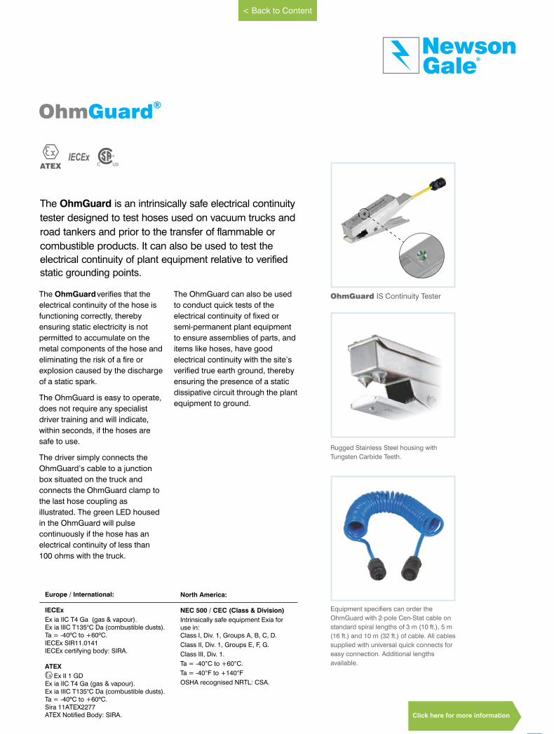
The OhmGuardverifies that the
electrical continuity of the hose is
functioning correctly, thereby
ensuring static electricity is not
permitted to accumulate on the
metal components of the hose and
eliminating the risk of a fire or
explosion caused by the discharge
of a static spark.
The OhmGuard is easy to operate,
does not require any specialist
driver training and will indicate,
within seconds, if the hoses are
safe to use.
The driver simply connects the
OhmGuard’s cable to a junction
box situated on the truck and
connects the OhmGuard clamp to
the last hose coupling as
illustrated. The green LED housed
in the will pulse OhmGuard
continuously if the hose has an
electrical continuity of less than
100 ohms with the truck.
The can also be used OhmGuard
to conduct quick tests of the
electrical continuity of fixed or
semi-permanent plant equipment
to ensure assemblies of parts, and
items like hoses, have good
electrical continuity with the site’s
verified true earth ground, thereby
ensuring the presence of a static
dissipative circuit through the plant
equipment to ground.
OhmGuard IS Continuity Tester
Rugged Stainless Steel housing with
Tungsten Carbide Teeth.
Equipment specifiers can order the
OhmGuard with 2-pole Cen-Stat cable on
standard spiral lengths of 3 m (10 ft.), 5 m
(16 ft.) and 10 m (32 ft.) of cable. All cables
supplied with universal quick connects for
easy connection. Additional lengths
available.
27
GaleNewson
®
The OhmGuard is an intrinsically safe electrical continuity
tester designed to test hoses used on vacuum trucks and
road tankers and prior to the transfer of flammable or
combustible products. It can also be used to test the
electrical continuity of plant equipment relative to verified
static grounding points.
IECExATEX
Ohm ®Guard
North America:
NEC 500 / CEC (Class & Division)
Intrinsically safe equipment Exia for use in:Class I, Div. 1, Groups A, B, C, D.
Class II, Div. 1, Groups E, F, G.
Class III, Div. 1.
Ta = -40°C to +60°C.
Ta = -40°F to +140°F
OSHA recognised NRTL: CSA.
Europe / International:
IECEx
Ex ia IIC T4 Ga (gas & vapour).Ex ia IIIC T135°C Da (combustible dusts).Ta = -40ºC to +60ºC.IECEx SIR11.0141IECEx certifying body: SIRA.
ATEX
Ex II 1 GDEx ia IIC T4 Ga (gas & vapour).Ex ia IIIC T135°C Da (combustible dusts).Ta = -40ºC to +60ºC.Sira 11ATEX2277ATEX Notified Body: SIRA.
www.newson-gale.co.uk
< Back to Content
Click here for more information
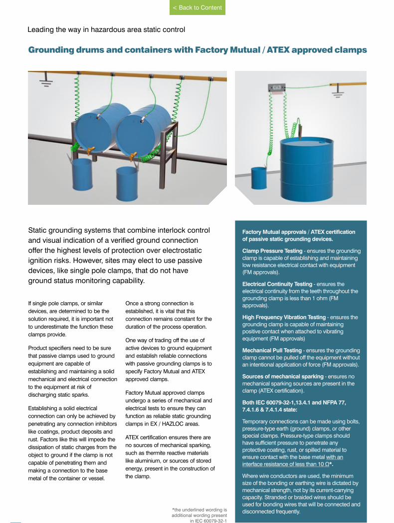
28
Leading the way in hazardous area static control
Static grounding systems that combine interlock control
and visual indication of a verified ground connection
offer the highest levels of protection over electrostatic
ignition risks. However, sites may elect to use passive
devices, like single pole clamps, that do not have
ground status monitoring capability.
If single pole clamps, or similar
devices, are determined to be the
solution required, it is important not
to underestimate the function these
clamps provide.
Product specifiers need to be sure
that passive clamps used to ground
equipment are capable of
establishing and maintaining a solid
mechanical and electrical connection
to the equipment at risk of
discharging static sparks.
Establishing a solid electrical
connection can only be achieved by
penetrating any connection inhibitors
like coatings, product deposits and
rust. Factors like this will impede the
dissipation of static charges from the
object to ground if the clamp is not
capable of penetrating them and
making a connection to the base
metal of the container or vessel.
Once a strong connection is
established, it is vital that this
connection remains constant for the
duration of the process operation.
One way of trading off the use of
active devices to ground equipment
and establish reliable connections
with passive grounding clamps is to
specify Factory Mutual and ATEX
approved clamps.
Factory Mutual approved clamps
undergo a series of mechanical and
electrical tests to ensure they can
function as reliable static grounding
clamps in EX / HAZLOC areas.
ATEX certification ensures there are
no sources of mechanical sparking,
such as thermite reactive materials
like aluminium, or sources of stored
energy, present in the construction of
the clamp.
Grounding drums and containers with Factory Mutual / ATEX approved clamps
Factory Mutual approvals / ATEX certification
of passive static grounding devices.
Clamp Pressure Testing - ensures the grounding
clamp is capable of establishing and maintaining
low resistance electrical contact with equipment
(FM approvals).
Electrical Continuity Testing - ensures the
electrical continuity from the teeth throughout the
grounding clamp is less than 1 ohm (FM
approvals).
High Frequency Vibration Testing - ensures the
grounding clamp is capable of maintaining
positive contact when attached to vibrating
equipment (FM approvals)
Mechanical Pull Testing - ensures the grounding
clamp cannot be pulled off the equipment without
an intentional application of force (FM approvals).
Sources of mechanical sparking - ensures no
mechanical sparking sources are present in the
clamp (ATEX certification).
Both IEC 60079-32-1,13.4.1 and NFPA 77,
7.4.1.6 & 7.4.1.4 state:
Temporary connections can be made using bolts,
pressure-type earth (ground) clamps, or other
special clamps. Pressure-type clamps should
have sufficient pressure to penetrate any
protective coating, rust, or spilled material to
ensure contact with the base metal with an
interface resistance of less than 10 Ω*.
Where wire conductors are used, the minimum
size of the bonding or earthing wire is dictated by
mechanical strength, not by its current-carrying
capacity. Stranded or braided wires should be
used for bonding wires that will be connected and
disconnected frequently.*the underlined wording isadditional wording present
in IEC 60079-32-1
www.newson-gale.co.uk
< Back to Content

29
GaleNewson
®
ATEX APPROVED
F M
Stainless Steel single pole reels Powder Coated single pole reelsVESX45 standard size heavy duty clamp
VESX90 large size heavy duty clamp VESX45 doubled ended clamp assembly Stainless Steel C-clamp
www.newson-gale.co.uk
Cen-Stat TM
< Back to Content
Click here for more information
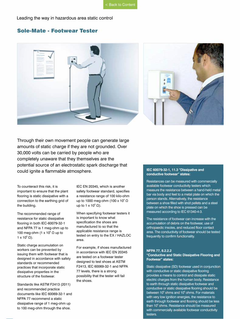
30
Leading the way in hazardous area static control
Through their own movement people can generate large
amounts of static charge if they are not grounded. Over
30,000 volts can be carried by people who are
completely unaware that they themselves are the
potential source of an electrostatic spark discharge that
could ignite a ammable atmosphere.
To counteract this risk, it is
important to ensure that the plant
flooring is static dissipative with a
connection to the earthing grid of
the building.
The recommended range of
resistance for static dissipative
flooring in both IEC-60079-32-1
and NFPA 77 is 1 meg-ohm up to 6100 meg-ohm (1 x 10 Ω up to
81 x 10 Ω).
Static charge accumulation on
workers can be prevented by
issuing them with footwear that is
designed in accordance with safety
standards or recommended
practices that incorporate static
dissipative properties in the
structure of the footwear.
Standards like ASTM F2413 (2011)
and recommended practice
documents like IEC 60069-32-1 and
NFPA 77 recommend a static
dissipative range of 1 meg-ohm up
to 100 meg-ohm through the shoe.
IEC EN 20345, which is another
safety footwear standard, specifies
a resistance range of 100 kilo-ohm 3up to 1000 meg-ohm (100 x 10 Ω
9up to 1 x 10 Ω).
When specifying footwear testers it
is important to know what
specification the shoes are
manufactured to so that the
applicable resistance range is
tested on entry to the EX / HAZLOC
area.
For example, if shoes manufactured
in accordance with IEC EN 20345
are tested on a footwear tester
designed to test shoes at ASTM
F2413, IEC 60069-32-1 and NFPA
77 levels, there is a strong
possibility that the tester will fail
the shoes.
Sole-Mate - Footwear Tester
IEC 60079-32-1, 11.3 “Dissipative and
conductive footwear” states:
Resistances can be measured with commercially
available footwear conductivity testers which
measure the resistance between a hand-held metal
bar via body and feet to a metal plate on which the
person stands. Alternatively, the resistance
between a shoe filled with shot pellets and a steel
plate on which the shoe is pressed can be
measured according to IEC 61340-4-3.
The resistance of footwear can increase with the
accumulation of debris on the footwear, use of
orthopaedic insoles, and reduced floor contact
area. The conductivity of footwear should be tested
frequently to confirm functionality.
NFPA 77, 8.2.2.2
“Conductive and Static Dissipative Flooring and
Footwear” states:
Static dissipative (SD) footwear used in conjunction
with conductive or static dissipative flooring
provides a means to control and dissipate static
electric charges from the human body. Resistance
to earth through static dissipative footwear and
conductive or static dissipative flooring should be 6 8between 10 ohms and 10 ohms. For materials
with very low ignition energies, the resistance to
earth through footwear and flooring should be less 6than 10 ohms. Resistance should be measured
with commercially available footwear conductivity
testers.
www.newson-gale.co.uk
< Back to Content
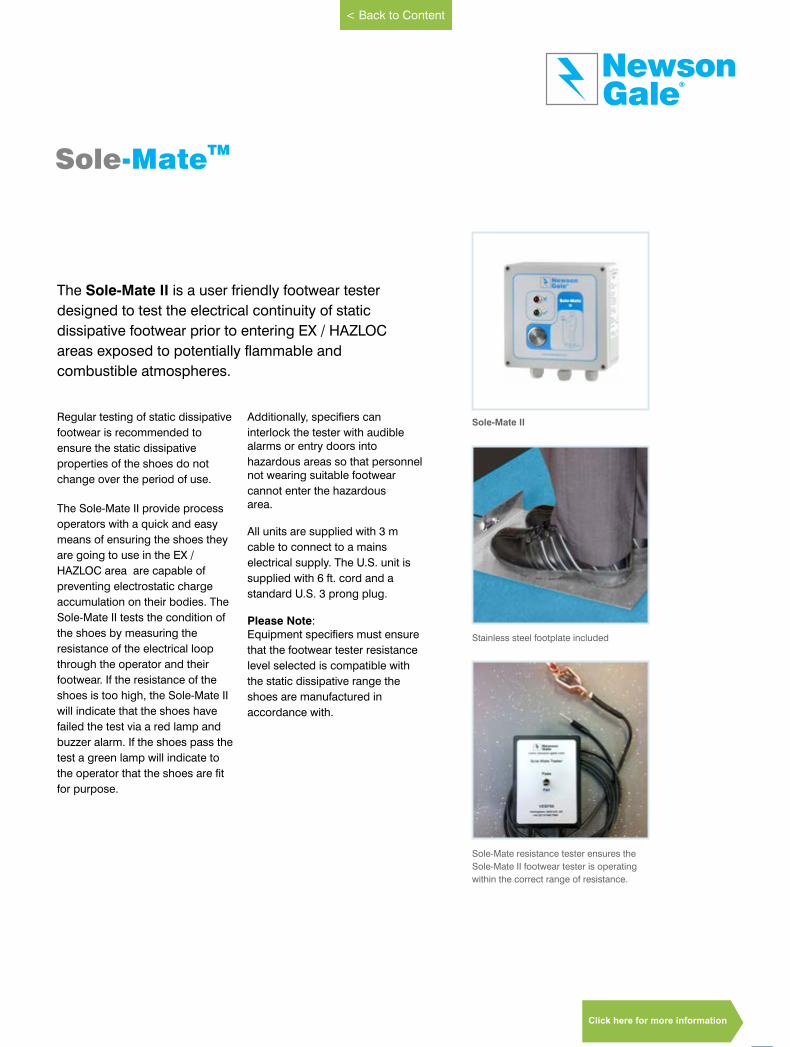
31
GaleNewson
®
The Sole-Mate II is a user friendly footwear tester
designed to test the electrical continuity of static
dissipative footwear prior to entering EX / HAZLOC
areas exposed to potentially flammable and
combustible atmospheres.
Regular testing of static dissipative
footwear is recommended to
ensure the static dissipative
properties of the shoes do not
change over the period of use.
The Sole-Mate II provide process
operators with a quick and easy
means of ensuring the shoes they
are going to use in the EX /
HAZLOC area are capable of
preventing electrostatic charge
accumulation on their bodies. The
Sole-Mate II tests the condition of
the shoes by measuring the
resistance of the electrical loop
through the operator and their
footwear. If the resistance of the
shoes is too high, the Sole-Mate II
will indicate that the shoes have
failed the test via a red lamp and
buzzer alarm. If the shoes pass the
test a green lamp will indicate to
the operator that the shoes are fit
for purpose.
Additionally, specifiers can
interlock the tester with audiblealarms or entry doors into
hazardous areas so that personnelnot wearing suitable footwear
cannot enter the hazardousarea.
All units are supplied with 3 m
cable to connect to a mains
electrical supply. The U.S. unit is
supplied with 6 ft. cord and a
standard U.S. 3 prong plug.
Please Note: Equipment specifiers must ensure
that the footwear tester resistance
level selected is compatible with
the static dissipative range the
shoes are manufactured in
accordance with.
Sole-MateTM
Sole-Mate II
Stainless steel footplate included
Sole-Mate resistance tester ensures the
Sole-Mate II footwear tester is operating
within the correct range of resistance.
www.newson-gale.co.uk
< Back to Content
Click here for more information
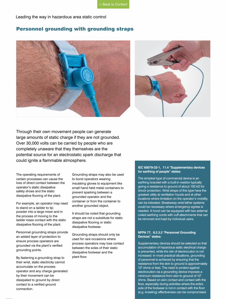
Leading the way in hazardous area static control
Through their own movement people can generate
large amounts of static charge if they are not grounded.
Over 30,000 volts can be carried by people who are
completely unaware that they themselves are the
potential source for an electrostatic spark discharge that
could ignite a ammable atmosphere.
The operating requirements of
certain processes can cause theloss of direct contact between the
operator’s static dissipativesafety shoes and the static
dissipative flooring of the plant.
For example, an operator may need
to stand on a ladder to tippowder into a large mixer and in
the process of moving to theladder loses contact with the static
dissipative flooring of the plant.
Personnel grounding straps provide
an added layer of protection to
ensure process operators are
grounded via the plant’s verified
grounding points.
By fastening a grounding strap to
their wrist, static electricity cannot
accumulate on the process
operator and any charge generated
by their movement can be
dissipated to ground by direct
contact to a verified ground
connection.
Grounding straps may also be used
to bond operators wearing
insulating gloves to equipment like
small hand held metal containers to
prevent sparking between a
grounded operator and the
container or from the container to
another grounded object.
It should be noted that grounding
straps are not a substitute for static
dissipative flooring or static
dissipative footwear.
Grounding straps should only be
used for rare occasions where
process operators may lose contact
between the soles of their static
dissipative footwear and the
plant floor.
Personnel grounding with grounding straps
IEC 60079-32-1, 11.4 “Supplementary devices
for earthing of people” states:
The simplest type of commercial device is an
earthing bracelet with a built-in resistor typically
giving a resistance to ground of about 100 kΩ for
shock protection. Wrist straps of this type have the
greatest utility at ventilation hoods and at other
locations where limitation on the operator’s mobility
can be tolerated. Breakaway wrist tether systems
could be necessary where emergency egress is
needed. A hood can be equipped with two external
coiled earthing cords with cuff attachments that can
be removed and kept by individual users.
NFPA 77, 8.2.3.2 “Personnel Grounding
Devices” states:
Supplementary devices should be selected so that
accumulation of hazardous static electrical charge
is prevented, while the risk of electrocution is not
increased. In most practical situations, grounding
of personnel is achieved by ensuring that the
resistance from the skin to ground is approximately 810 ohms or less. The need to protect against
electrocution via a grounding device imposes a 6minimum resistance from skin to ground of 10
ohms. Based on skin contact and contact with the
floor, especially during activities where the entire
sole of the footwear is not in contact with the floor
(e.g. kneeling) effectiveness can be compromised.
www.newson-gale.co.uk32
< Back to Content
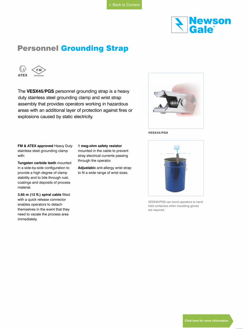
FM & ATEX approved Heavy Duty
stainless steel grounding clamp
with:
Tungsten carbide teeth mounted
in a side-by-side configuration to
provide a high degree of clamp
stability and to bite through rust,
coatings and deposits of process
material.
3.65 m (12 ft.) spiral cable fitted
with a quick release connector
enables operators to detach
themselves in the event that they
need to vacate the process area
immediately.
1 meg-ohm safety resistor
mounted in the cable to prevent
stray electrical currents passing
through the operator.
Adjustable anti-allergy wrist strap
to fit a wide range of wrist sizes.
VESX45/PGS
VESX45/PGS can bond operators to hand
held containers when insulating gloves
are required.
33
GaleNewson
®
The VESX45/PGS personnel grounding strap is a heavy
duty stainless steel grounding clamp and wrist strap
assembly that provides operators working in hazardous
areas with an additional layer of protection against fires or
explosions caused by static electricity.
ATEX
Personnel Grounding Strap
APPROVED
F M
www.newson-gale.co.uk
< Back to Content
Click here for more information
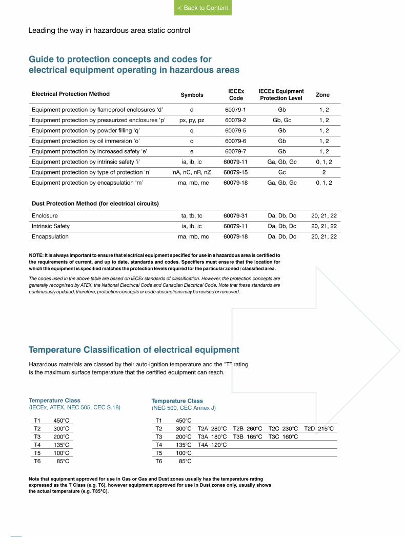
Guide to protection concepts and codes for electrical equipment operating in hazardous areas
NOTE: It is always important to ensure that electrical equipment specified for use in a hazardous area is certified to
the requirements of current, and up to date, standards and codes. Specifiers must ensure that the location for
which the equipment is specified matches the protection levels required for the particular zoned / classified area.
The codes used in the above table are based on IECEx standards of classification. However, the protection concepts are
generally recognised by ATEX, the National Electrical Code and Canadian Electrical Code. Note that these standards are
continuously updated, therefore, protection concepts or code descriptions may be revised or removed.
Note that equipment approved for use in Gas or Gas and Dust zones usually has the temperature rating
expressed as the T Class (e.g. T6), however equipment approved for use in Dust zones only, usually shows
the actual temperature (e.g. T85°C).
T1 450°C
T2 300°C
T3 200°C
T4 135°C
T5 100°C
T6 85°C
T1 450°C
T2 300°C T2A 280°C T2B 260°C T2C 230°C T2D 215°C
T3 200°C T3A 180°C T3B 165°C T3C 160°C
T4 135°C T4A 120°C
T5 100°C
T6 85°C
Temperature Class(NEC 500, CEC Annex J)
Hazardous materials are classed by their auto-ignition temperature and the “T” rating
is the maximum surface temperature that the certified equipment can reach.
Temperature Classification of electrical equipment
Temperature Class (IECEx, ATEX, NEC 505, CEC S.18)
Equipment protection by flameproof enclosures ‘d’ d 60079-1 Gb 1, 2
Equipment protection by pressurized enclosures ‘p’ px, py, pz 60079-2 Gb, Gc 1, 2
Equipment protection by powder filling ‘q’ q 60079-5 Gb 1, 2
Equipment protection by oil immersion ‘o’ o 60079-6 Gb 1, 2
Equipment protection by increased safety ‘e’ e 60079-7 Gb 1, 2
Equipment protection by intrinsic safety ‘i’ ia, ib, ic 60079-11 Ga, Gb, Gc 0, 1, 2
Equipment protection by type of protection ‘n’ nA, nC, nR, nZ 60079-15 Gc 2
Equipment protection by encapsulation ‘m’ ma, mb, mc 60079-18 Ga, Gb, Gc 0, 1, 2
Dust Protection Method (for electrical circuits)
Enclosure ta, tb, tc 60079-31 Da, Db, Dc 20, 21, 22
Intrinsic Safety ia, ib, ic 60079-11 Da, Db, Dc 20, 21, 22
Encapsulation ma, mb, mc 60079-18 Da, Db, Dc 20, 21, 22
Electrical Protection Method Symbols ZoneIECExCode
IECEx EquipmentProtection Level
34
Leading the way in hazardous area static control
www.newson-gale.co.uk
< Back to Content
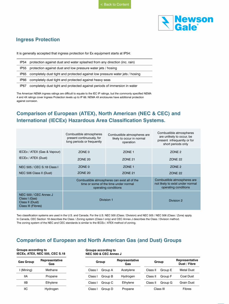
It is generally accepted that ingress protection for Ex equipment starts at IP54:
IP54 protection against dust and water splashed from any direction (inc. rain)
IP55 protection against dust and low pressure water jets / hosing
IP65 completely dust tight and protected against low pressure water jets / hosing
IP66 completely dust tight and protected against heavy seas
IP67 completely dust tight and protected against periods of immersion in water
The American NEMA ingress ratings are difficult to equate to the IEC IP ratings, but the commonly specified NEMA
4 and 4X ratings cover Ingress Protection levels up to IP 66. NEMA 4X enclosures have additional protection
against corrosion.
Two classification systems are used in the U.S. and Canada. For the U.S. NEC 500 (Class / Division) and NEC 505 / NEC 506 (Class / Zone) apply.
In Canada, CEC Section 18 describes the Class / Zoning system (Class I only) and CEC Annex J describes the Class / Division method.
The zoning system of the NEC and CEC standards is similar to the IECEx / ATEX method of zoning.
Comparison of European (ATEX), North American (NEC & CEC) and
International (IECEx) Hazardous Area Classification Systems.
Ingress Protection
Combustible atmospheres present continuously, for long periods or frequently
Combustible atmospheres are likely to occur in normal
operation
Combustible atmospheres are unlikely to occur, be
present infrequently or for short periods only
IECEx / ATEX (Gas & Vapour) ZONE 0
ZONE 20
ZONE 0
ZONE 2
ZONE 22
ZONE 2
ZONE 1
ZONE 21
ZONE 1 NEC 505 / CEC S.18 Class I
Combustible atmospheres can exist all of the time or some of the time under normal
operating conditions
Combustible atmospheres are not likely to exist under normal
operating conditions
NEC 500 / CEC Annex JClass I (Gas)Class II (Dust)Class III (Fibres)
Division 1 Division 2
NEC 506 Class II (Dust) ZONE 20 ZONE 21 ZONE 22
IECEx / ATEX (Dust)
35
GaleNewson
®
Comparison of European and North American Gas (and Dust) Groups
Groups according toIECEx, ATEX, NEC 505, CEC S.18
Gas Group Representative
Gas
I (Mining)
IIA
IIB
IIC
Methane
Propane
Ethylene
Hydrogen
Groups according toNEC 500 & CEC Annex J
Group
Group A
Group B
Group C
Group D
RepresentativeDust / Fibre
Metal Dust
Coal Dust
Grain Dust
Fibres
Class I
Class I
Class I
Class I
Group
Group E
Group F
Group G
Class II
Class II
Class II
Class III
RepresentativeGas
Acetylene
Hydrogen
Ethylene
Propane
www.newson-gale.co.uk
< Back to Content
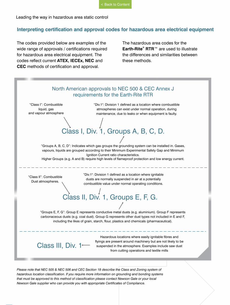
The codes provided below are examples of the
wide range of approvals / certifications required
for hazardous area electrical equipment. The
codes reflect current ATEX, IECEx, NEC and
CEC methods of certification and approval.
The hazardous area codes for the®Earth-Rite RTR™ are used to illustrate
the differences and similarities between
these methods.
Interpreting certification and approval codes for hazardous area electrical equipment
North American approvals to NEC 500 & CEC Annex J requirements for the Earth-Rite RTR
“Div.1": Division 1 defined as a location where combustible
atmospheres can exist under normal operation, during
maintenance, due to leaks or when equipment is faulty.
Class I, Div. 1, Groups A, B, C, D.
“Class I”: Combustible
liquid, gas and vapour atmosphere
“Groups A, B, C, D”: Indicates which gas groups the grounding system can be installed in. Gases,
vapours, liquids are grouped according to their Minimum Experimental Safety Gap and Minimum
Ignition Current ratio characteristics.Higher Groups (e.g. A and B) require high levels of flameproof protection and low energy current.
“Div.1": Division 1 defined as a location where ignitable
dusts are normally suspended in air at a potentially
combustible value under normal operating conditions.
Class II, Div. 1, Groups E, F, G.
“Class II”: Combustible
Dust atmospheres.
“Groups E, F, G”: Group E represents conductive metal dusts (e.g. aluminium). Group F represents
carbonaceous dusts (e.g. coal dust). Group G represents other dust types not included in E and F,
including the likes of grain, starch, flour, plastics and chemicals (pharmaceutical).
Class III, Div. 1
Hazardous locations where easily ignitable fibres and
flyings are present around machinery but are not likely to be
suspended in the atmosphere. Examples include saw dust
from cutting operations and textile mills
Please note that NEC 505 & NEC 506 and CEC Section 18 describe the Class and Zoning system of
hazardous location classification. If you require more information on grounding and bonding systems
that must be approved to this method of classification please contact Newson Gale or your local
Newson Gale supplier who can provide you with appropriate Certificates of Compliance.
36
Leading the way in hazardous area static control
www.newson-gale.co.uk
< Back to Content
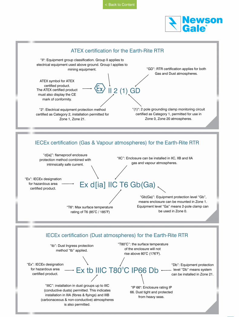
II 2 (1) GD
“(1)": 2 pole grounding clamp monitoring circuit
certified as Category 1, permitted for use in
Zone 0, Zone 20 atmospheres.
“GD”: RTR certification applies for both
Gas and Dust atmospheres.
“2": Electrical equipment protection method
certified as Category 2, installation permitted for
Zone 1, Zone 21.
“II": Equipment group classification. Group II applies to
electrical equipment used above ground. Group I applies to
mining equipment.
ATEX symbol for ATEX
certified product.The ATEX certified product
must also display the CE
mark of conformity.
ATEX certification for the Earth-Rite RTR
Ex d[ia] IIC T6 Gb(Ga)
“d[ia]”: flameproof enclosure
protection method combined with
intrinsically safe current.
“IIC”: Enclosure can be installed in IIC, IIB and IIA
gas and vapour atmospheres.
“T6": Max surface temperatureo o rating of T6 (85 C / 185 F)
“Gb(Ga)”: Equipment protection level “Gb”,
means enclosure can be mounted in Zone 1.
Equipment level “Ga” means 2-pole clamp can
be used in Zone 0.
“Ex”: IECEx designation
for hazardous area
certified product.
IECEx certification (Gas & Vapour atmospheres) for the Earth-Rite RTR
“IP 66": Enclosure rating IP
66. Dust tight and protected
from heavy seas.
oEx tb IIIC T80 C IP66 Db“Ex”: IECEx designation
for hazardous area
certified product.
“tb”: Dust Ingress protection
method “tb” applied.
“IIIC”: installation in dust groups up to IIIC
(conductive dusts) permitted. This indicates
installation in IIIA (fibres & flyings) and IIIB
(carbonaceous & non-conductive) atmospheres
is also permitted.
o “T80 C”: the surface temperature
of the enclosure will not o orise above 80 C (176 F).
“Db”: Equipment protection
level “Db” means system
can be installed in Zone 21.
IECEx certification (Dust atmospheres) for the Earth-Rite RTR
37
GaleNewson
®
www.newson-gale.co.uk
< Back to Content
On-Going Maintenance of Static Control Procedures and Equipment
Generally, there are two main elements to
the physical side of the static grounding
system. These are firstly, the fixed
grounding network. This may take the form
of a copper strip or bar running along the
walls and connected to a number of
grounding rods, pits or grids, driven into the
ground. This network should be tested
periodically, with respect to ground, to
ensure that it is maintaining a low (typically
less than 10 ohm) resistance to ground.
These tests are fairly specialist, and may be
carried out by an outside contractor, often in
conjunction with tests on lightning
protection equipment. A typical test period
would be every 11 or 13 months (so that
over a period of time, the tests cycle
through the seasons). A main point to look
out for when testing the network, is any
significant variation with previous tests,
which could show deterioration. This also
highlights the need for keeping good
records. If the grounding network meets the
necessary low resistance, then any metal
object connected to it will also
be grounded.
The second part of the physical system is
the devices used to connect plant and
equipment to the grounding network. If a
piece of plant is fixed, such as the body of
a mixing machine, then a simple strong
bonding cable can be used to permanently
attach it to the grounding network. However,
movable plant, such as the mixer's product
bowl, or a 200 litre drum is harder to
ground, and the standards recommend that
a cable with strong mechanical strength
and a “designed for purpose” clamp are
used to make a temporary connection
when the item is in use.
These connections can be tested using an
intrinsically safe ground lead tester or ohm
meter and the results for each lead
recorded. The tester or meter will be used
to complete a circuit between the grounding
point and the plant item to be grounded; for
the purpose of testing clamps and their
cables or reels, this may take the form of a
clean piece of metal placed in the clamp
jaw. The tester or meter leads may then be
connected between the piece of metal and
the grounding point in order to complete
the circuit and obtain a reading.
These types of flexible connector should be
tested more frequently than fixed ones;
typically once every three months in the
case of ground leads and after every re-
assembly, in the case of bonds on
removable ducting sections. A bond to a
fixed piece of plant may be tested on an
annual or six-monthly basis.
The on-going training of personnel may be
more difficult to maintain, partly because of
disruption to production, and also, as it can
be difficult to keep things interesting.
Training today need not just take the form
of a classroom lecture; new learning media
such as interactive CD-ROM provides
flexible training solutions to accommodate
the varying needs of production schedules,
shifts and locations. Team leaders can
quickly assess the knowledge level of
existing or new operators and programme
one or two hours per week to bring
knowledge levels up.
Today, it is common for companies to use
continuous monitoring of ground
connections and systems incorporating
interlocks that prevent a static-generating
operation from taking place unless the
ground is made. Such systems mean that
the frequency of lead testing can be
reduced, as the systems are providing a
continuous test to a pre-determined
resistance level. They also mean that the
grounding measures are more likely to be
remembered during operation, as a visual
indication of ground condition, such as the
LED in a self-testing clamp, act as a strong
reminder to use the device.
38
Leading the way in hazardous area static control
Once appropriate static control procedures and equipment have been put in place,
it is vital that a high level of static awareness is maintained. The three principles of a
successful, on-going static control policy are:
I. Regular testing of the equipment used including logging of results.
ii. Frequent awareness training for operators and staff, particularly new employees.
iii. Reference to the standards when changes take place, such as the introduction
of new types of plant or materials.
www.newson-gale.co.uk
< Back to Content
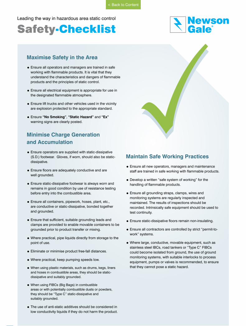
40
Leading the way in hazardous area static control
Maximise Safety in the Area
= Ensure all operators and managers are trained in safe
working with flammable products. It is vital that they
understand the characteristics and dangers of flammable
products and the principles of static control.
= Ensure all electrical equipment is appropriate for use in
the designated flammable atmosphere.
= Ensure lift trucks and other vehicles used in the vicinity
are explosion protected to the appropriate standard.
= Ensure “No Smoking”, “Static Hazard” and “Ex”
warning signs are clearly posted.
Minimise Charge Generation
and Accumulation
= Ensure operators are supplied with static-dissipative
(S.D.) footwear. Gloves, if worn, should also be static-
dissipative.
= Ensure floors are adequately conductive and are
well grounded.
= Ensure static-dissipative footwear is always worn and
remains in good condition by use of resistance testing
before entry into the combustible area.
= Ensure all containers, pipework, hoses, plant, etc.,
are conductive or static-dissipative, bonded together
and grounded.
= Ensure that sufficient, suitable grounding leads and
clamps are provided to enable movable containers to be
grounded prior to product transfer or mixing.
=Where practical, pipe liquids directly from storage to the
point of use.
= Eliminate or minimise product free-fall distances.
=Where practical, keep pumping speeds low.
= When using plastic materials, such as drums, kegs, liners
and hoses in combustible areas, they should be static-
dissipative and suitably grounded.
= When using FIBCs (Big Bags) in combustible
areas or with potentially combustible dusts or powders,
they should be “Type C” static-dissipative and
suitably grounded.
= The use of anti-static additives should be considered in
low conductivity liquids if they do not harm the product.
Maintain Safe Working Practices
= Ensure all new operators, managers and maintenance
staff are trained in safe working with flammable products.
= Develop a written “safe system of working” for the
handling of flammable products.
= Ensure all grounding straps, clamps, wires and
monitoring systems are regularly inspected and
maintained. The results of inspections should be
recorded. Intrinsically safe equipment should be used to
test continuity.
= Ensure static-dissipative floors remain non-insulating.
= Ensure all contractors are controlled by strict “permit-to-
work” systems.
=Where large, conductive, movable equipment, such as
stainless steel IBCs, road tankers or “Type C” FIBCs
could become isolated from ground, the use of ground
monitoring systems, with suitable interlocks to process
equipment, pumps or valves is recommended, to ensure
that they cannot pose a static hazard.
Safety-Checklist GaleNewson
®
< Back to Content
www.newson-gale.co.uk
Examples of how different
operations can result in
discharges of static electricity
It’s worth noting that the common denominator in these
incidents was that the operator(s) did not have a visual
reference point for a verified ground connection.
www.news.bbc.co.uk
www.csb.gov
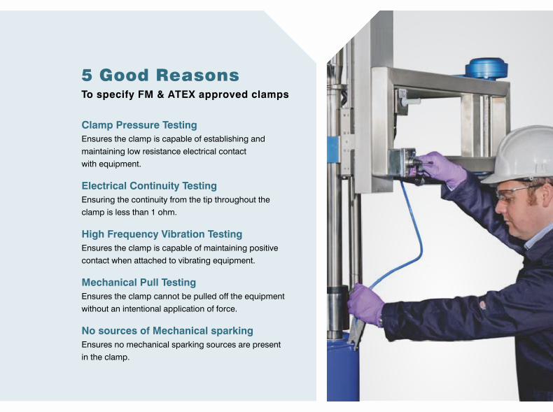
NG
UK
G&
B C
ata
log
ue 0
90
71
5 R
1
United Kingdom
Newson Gale Ltd
Omega House
Private Road 8
Colwick, Nottingham
NG4 2JX, UK
+44 (0)115 940 7500
Deutschland
Newson Gale GmbH
Ruhrallee 185
45136 Essen
Deutschland
+49 (0)201 89 45 245
South East Asia
Newson Gale S.E.A. Pte Ltd
136 Joo Seng Road
#03-01
Singapore
368360
+65 6420 0443
United States
Newson Gale Inc
460 Faraday Avenue
Bldg C
Jackson, NJ 08527
USA
+1 732 961 7610
GaleNewson
®
www.newson-gale.co.uk
®GaleNewson Static electricity is an ever-present and
significant hazard for operations taking
place in flammable, combustible or
potentially explosive atmospheres. The
uncontrolled build up and discharge of
electrostatic charge must be avoided in
these environments to protect people,
plant, processes and the environment.
Newson Gale’s wide range of static
grounding solutions can control and
mitigate these risks, creating a safer
and more productive working
environment.
www.newson-gale.co.uk
Copyright Newson Gale Ltd. Permission is granted to copy and circulate
parts of this publication for internal training and educational use provided
full acknowledgment of Newson Gale Ltd as its source is shown.
5 Good ReasonsTo specify FM & ATEX approved clamps
Clamp Pressure Testing
Ensures the clamp is capable of establishing and
maintaining low resistance electrical contact
with equipment.
Electrical Continuity Testing
Ensuring the continuity from the tip throughout the
clamp is less than 1 ohm.
High Frequency Vibration Testing
Ensures the clamp is capable of maintaining positive
contact when attached to vibrating equipment.
Mechanical Pull Testing
Ensures the clamp cannot be pulled off the equipment
without an intentional application of force.
No sources of Mechanical sparking
Ensures no mechanical sparking sources are present
in the clamp.

Thank you for reading this data sheet.
For pricing or for further information, please contact us at our UK Office, using the details below.
UK OfficeKeison Products,
P.O. Box 2124, Chelmsford, Essex, CM1 3UP, England.Tel: +44 (0)330 088 0560Fax: +44 (0)1245 808399
Email: [email protected]
Please note - Product designs and specifications are subject to change without notice. The user is responsible for determining the suitability of this product.