plane waves, transmission lines and waveguides - Jenn, David C
Understanding
Transmission Lines
8/8/2012 Larry Benko, W0QE 1
www.w0qe.com
Intended Audience
• Some limited transmission line exposure including
concepts of SWR, reflections, dB, and loss
• Grasp basic electrical concepts such as
voltage/current phase and Kirchoff’s circuit laws.
• Impedance replaces resistance and terms like
50+j20 Ω should be familiar
8/8/2012 Larry Benko, W0QE 2
Presentation Format
• No wave equations or telegrapher’s equations(http://en.wikipedia.org/wiki/Transmission_line#Matched_load
• Software simulation is invaluable for better
understanding of the concepts
• Inexpensive test equipment allows measurements
that only a lab could make 20 years ago
• Transmission lines and impedance matching are
closely related
8/8/2012 Larry Benko, W0QE 3
Transmission Lines
• Deliver RF signals to another location efficiently
• Early transmitters did not use transmission lines
but transmission lines pre-date radio
• 2/4 wire open wire lines, flexible coax, hard line,
twisted pair, stripline, microstrip, wave guide, etc.
• Computer motherboards, Ethernet, USB cables
• Nearly all digital signals are RF these days
8/8/2012 Larry Benko, W0QE 4
Who Can You Believe?
• Too much misinformation and incomplete
information exists in the amateur radio community
• Transient and steady state conditions are often
incorrectly mixed together
• All concepts presented have been measured in
hardware and simulated in software, often in
multiple programs, with total agreement
• Please challenge me on any topic
8/8/2012 Larry Benko, W0QE 5
Simulation Programs(currently available)
• LTSpice IV http://www.linear.com/designtools/software/ (Free)
Previously called SwitcherCAD, updated extremely oftenWinXP/7 32-64bit, Mac/Linux via Wine
• TLW v3.1 Comes with ARRL Antenna Handbook, WinXP/7 32-64bit
• SWR Calculator v1.2 http://www.vnahelp.com/products.html
(Free), WinXP/7 32-64bit, Not a simulation program but very useful
• Coax loss & power handling calculatorhttp://www.timesmicrowave.com/cgi-bin/calculate.pl (Free)Not a simulation program
8/8/2012 Larry Benko, W0QE 6
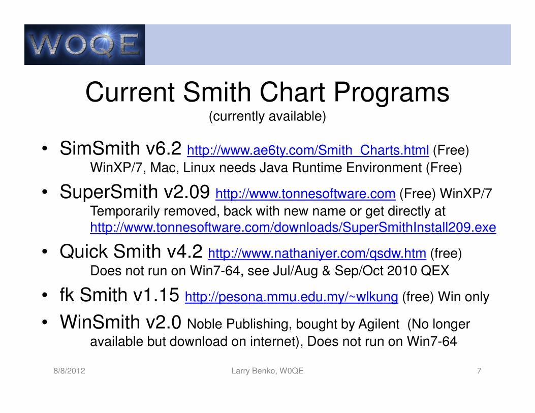
Current Smith Chart Programs(currently available)
• SimSmith v6.2 http://www.ae6ty.com/Smith_Charts.html (Free)
WinXP/7, Mac, Linux needs Java Runtime Environment (Free)
• SuperSmith v2.09 http://www.tonnesoftware.com (Free) WinXP/7
Temporarily removed, back with new name or get directly at http://www.tonnesoftware.com/downloads/SuperSmithInstall209.exe
• Quick Smith v4.2 http://www.nathaniyer.com/qsdw.htm (free)
Does not run on Win7-64, see Jul/Aug & Sep/Oct 2010 QEX
• fk Smith v1.15 http://pesona.mmu.edu.my/~wlkung (free) Win only
• WinSmith v2.0 Noble Publishing, bought by Agilent (No longer
available but download on internet), Does not run on Win7-64
8/8/2012 Larry Benko, W0QE 7
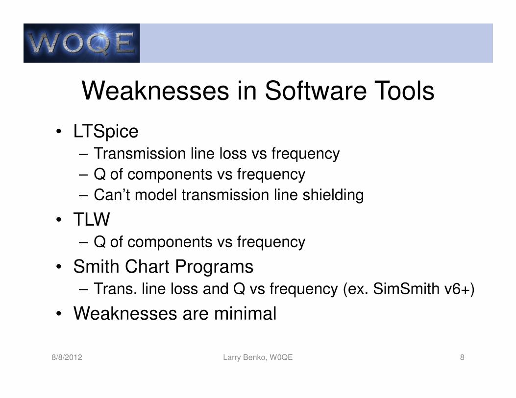
Weaknesses in Software Tools
• LTSpice– Transmission line loss vs frequency
– Q of components vs frequency
– Can’t model transmission line shielding
• TLW– Q of components vs frequency
• Smith Chart Programs– Trans. line loss and Q vs frequency (ex. SimSmith v6+)
• Weaknesses are minimal
8/8/2012 Larry Benko, W0QE 8
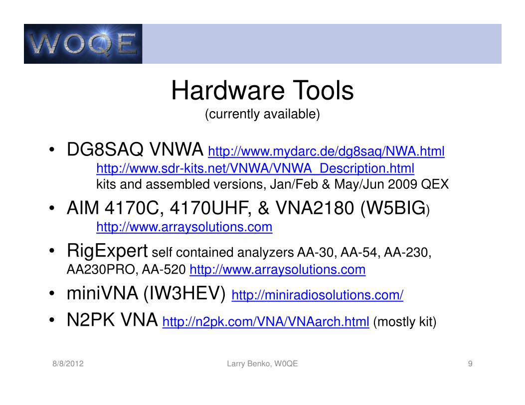
Hardware Tools(currently available)
• DG8SAQ VNWA http://www.mydarc.de/dg8saq/NWA.html
http://www.sdr-kits.net/VNWA/VNWA_Description.htmlkits and assembled versions, Jan/Feb & May/Jun 2009 QEX
• AIM 4170C, 4170UHF, & VNA2180 (W5BIG)
http://www.arraysolutions.com
• RigExpert self contained analyzers AA-30, AA-54, AA-230,
AA230PRO, AA-520 http://www.arraysolutions.com
• miniVNA (IW3HEV) http://miniradiosolutions.com/
• N2PK VNA http://n2pk.com/VNA/VNAarch.html (mostly kit)
8/8/2012 Larry Benko, W0QE 9
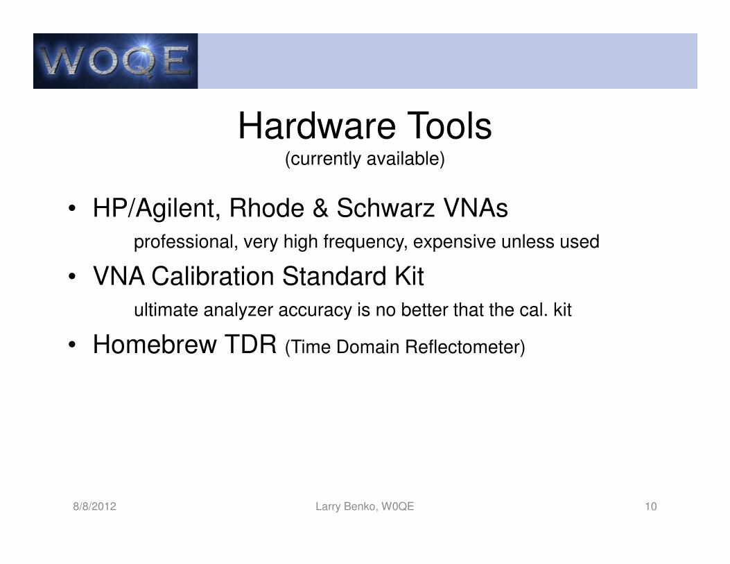
Hardware Tools(currently available)
• HP/Agilent, Rhode & Schwarz VNAs
professional, very high frequency, expensive unless used
• VNA Calibration Standard Kit
ultimate analyzer accuracy is no better that the cal. kit
• Homebrew TDR (Time Domain Reflectometer)
8/8/2012 Larry Benko, W0QE 10
dB (Decibel)
• Relative measurement, ratio of power or intensitywithout units
• Used in acoustics, optics, and electronics
• Convert to voltages or currents, dB = 10*log10(Po/Pi), dB = 20*log10(Vo/Vi) if impedance is constant
• 2x = 3dB, 4x = 6dB, 8x = 9dB, 1/2x = -3dB, 10x = 10dB, 5x =7dB, 100x = 20dB, .0001x = -40dB etc.
• Absolute dB terms (dBm, dBrnC0, dBW, dBV, dBuV)
• Impedance issues, double termination = -3.52dB
8/8/2012 Larry Benko, W0QE 11
How Do Transmission Lines Work?
• At every point along the transmission line the
currents in each wire are the same magnitude
and 180 degrees out of phase
• For coax, these currents are on the outside of
the center conductor and the inside of the shield
• Net AC current flow produces a magnetic field
that opposes current flow
• Transmission line currents produce the minimum
magnetic field which also minimizes radiation
8/8/2012 Larry Benko, W0QE 12
Other Currents on the Line
• A current can flow on both wires equally and is in
phase for open wire line or on the outside of the
shield for coax
• This is an antenna current that does radiate and
is generally unwanted
• Common mode chokes and winding in a loop are
techniques used to reduce this current to
acceptable levels
8/8/2012 Larry Benko, W0QE 13
Terminology of Currents
• Transmission line currents are also known as
differential or metallic currents
• Common mode currents are also known as
longitudinal or antenna currents
• Both types of currents can coexist but there is
always a small conversion from one type to the
other which can be problematic
8/8/2012 Larry Benko, W0QE 14
Properties of coaxial cable• Characteristic (surge) impedance
• Attenuation (matched loss) vs. frequency
• Power rating (current rating) matched vs. frequency
• Dielectric material (voltage breakdown, temperature rating)
• Center conductor (size and composition)
• Shield(s) material (shielding effectiveness)
• Outside jacket (weather, temperature, abrasion rating)
• Minimum bend radius, flexibility
• Physical size and connector compatibility
• Velocity factor
• Not all properties are important for a particular application
8/8/2012 Larry Benko, W0QE 15
Characteristic (Surge) Impedance
• Load impedance where no wave is reflected back
into the transmission line- Next 3 demonstration slides
• Notice how the ratio of the voltage divided by the
current is the surge impedance of the
transmission line independent of the load!
8/8/2012 Larry Benko, W0QE 16
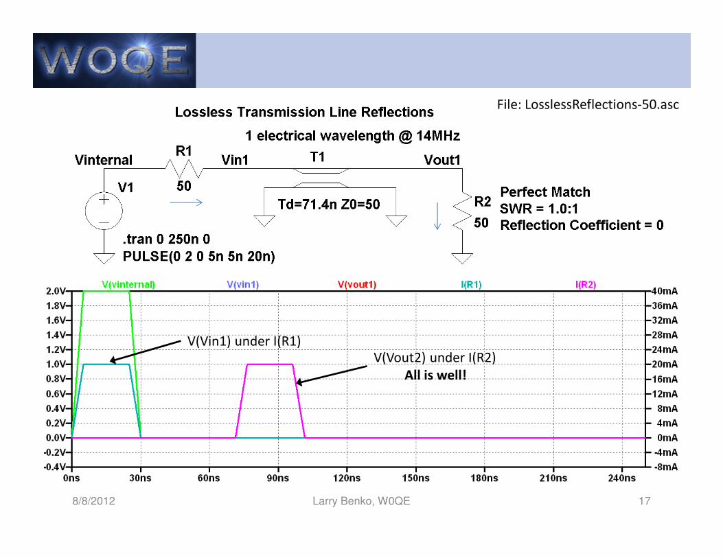
8/8/2012 Larry Benko, W0QE 17
V(Vin1) under I(R1)
V(Vout2) under I(R2)
All is well!
File: LosslessReflections-50.asc
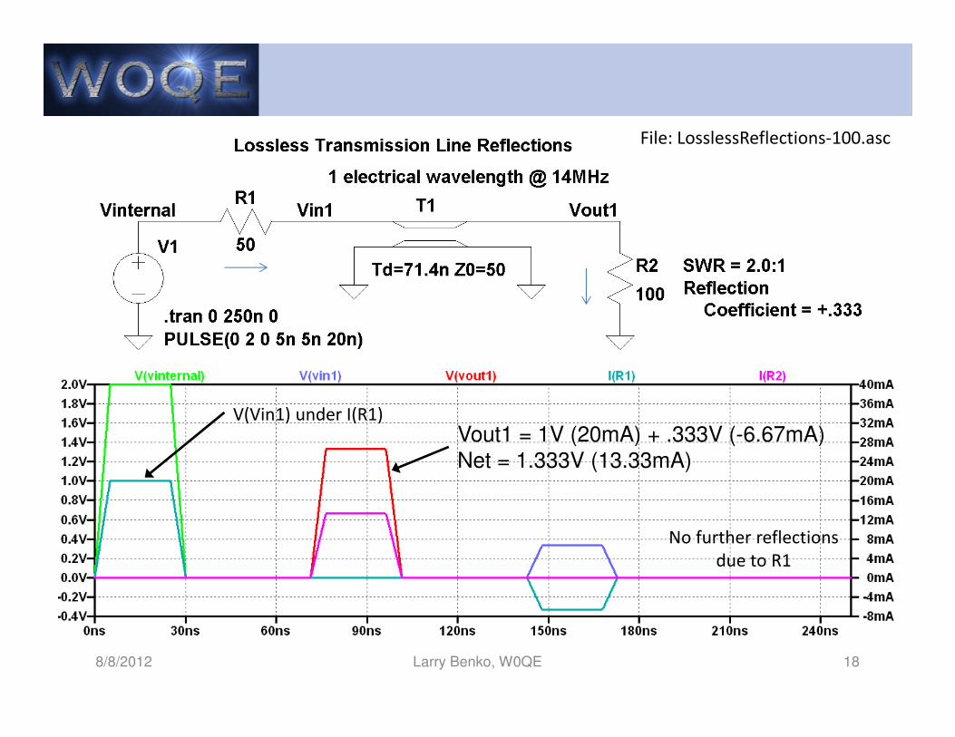
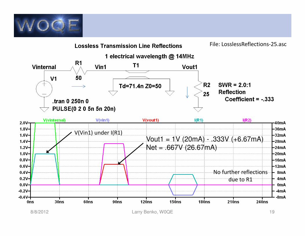
8/8/2012 Larry Benko, W0QE 18
V(Vin1) under I(R1)
No further reflections
due to R1
File: LosslessReflections-100.asc
Vout1 = 1V (20mA) + .333V (-6.67mA)
Net = 1.333V (13.33mA)
8/8/2012 Larry Benko, W0QE 19
V(Vin1) under I(R1)
No further reflections
due to R1
File: LosslessReflections-25.asc
Vout1 = 1V (20mA) - .333V (+6.67mA)
Net = .667V (26.67mA)
Surge Impedance Continued
• All forward & reflected waves have a V/I ratio that
equals the surge impedance of the line!
• Maximum power is delivered into the load when
the load impedance matches the surge
impedance of the transmission line
• Maximum power is delivered into a matched
transmission line if the transmitter output
impedance matches the surge impedance
8/8/2012 Larry Benko, W0QE 20
Surge Impedance Again
• Zo = per unit length, equivalent circuit no loss
• Why a particular impedance?– Maximum power 30Ω, minimum loss 77Ω, max. voltage
breakdown 60Ω (1929 Bell Laboratories) “modern coax”
– Maximum power per pound of copper 52Ω (F. Terman?)
– Today 75Ω, 50Ω, 52Ω, 53.5Ω, 25Ω, 80Ω, 93Ω, etc.
8/8/2012 Larry Benko, W0QE 21
L/C
SWR by other names• SWR (standing wave ratio)
– Maximum voltage in the line = forward + reflected voltage
– Minimum voltage in the line = forward - reflected voltage
– SWR is the maximum divided by the minimum voltage
• Reflection coefficient, return loss, and SWR– Different ways to tell the exact same story
– ρ (reflection coefficient) = Vr/Vf or Ir/If
– SWR = (1 + ρ)/ (1 - ρ)
– RL (return loss) = -20 log10(ρ)
• SWR decreases from load to source if line has loss
8/8/2012 Larry Benko, W0QE 22
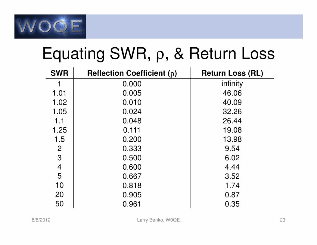
Equating SWR, ρ, & Return Loss
8/8/2012 Larry Benko, W0QE 23
SWR Reflection Coefficient (ρρρρ) Return Loss (RL)
1 0.000 infinity
1.01 0.005 46.06
1.02 0.010 40.09
1.05 0.024 32.26
1.1 0.048 26.44
1.25 0.111 19.08
1.5 0.200 13.98
2 0.333 9.54
3 0.500 6.02
4 0.600 4.445 0.667 3.52
10 0.818 1.7420 0.905 0.8750 0.961 0.35
8/8/2012 Larry Benko, W0QE 24
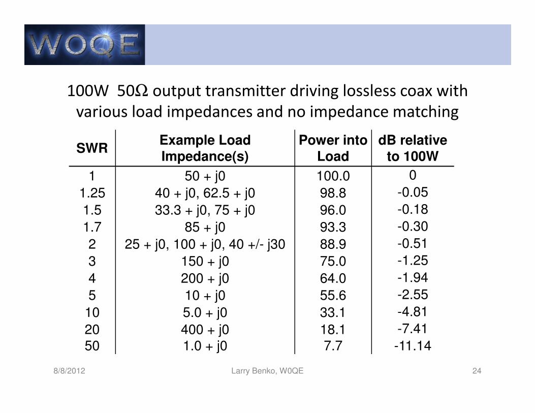
100W 50Ω output transmitter driving lossless coax with
various load impedances and no impedance matching
SWRExample Load Impedance(s)
Power into Load
dB relative to 100W
1 50 + j0 100.0 0
1.25 40 + j0, 62.5 + j0 98.8 -0.05
1.5 33.3 + j0, 75 + j0 96.0 -0.18
1.7 85 + j0 93.3 -0.30
2 25 + j0, 100 + j0, 40 +/- j30 88.9 -0.51
3 150 + j0 75.0 -1.25
4 200 + j0 64.0 -1.94
5 10 + j0 55.6 -2.55
10 5.0 + j0 33.1 -4.81
20 400 + j0 18.1 -7.41
50 1.0 + j0 7.7 -11.14
Effect of Reflections
• For continuous transmissions the signals
reflected back into the transmission line can
arrive at the transmitter with an amplitude from
zero to the original transmitter amplitude and at
any phase angle
• The impedance seen by the transmitter varies
and for high SWRs can be either very low, very
high, or highly reactive causing driving problems
for the transmitter
8/8/2012 Larry Benko, W0QE 25
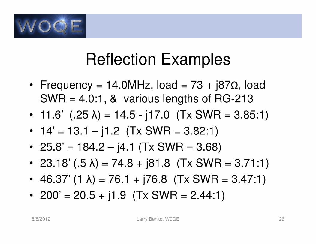
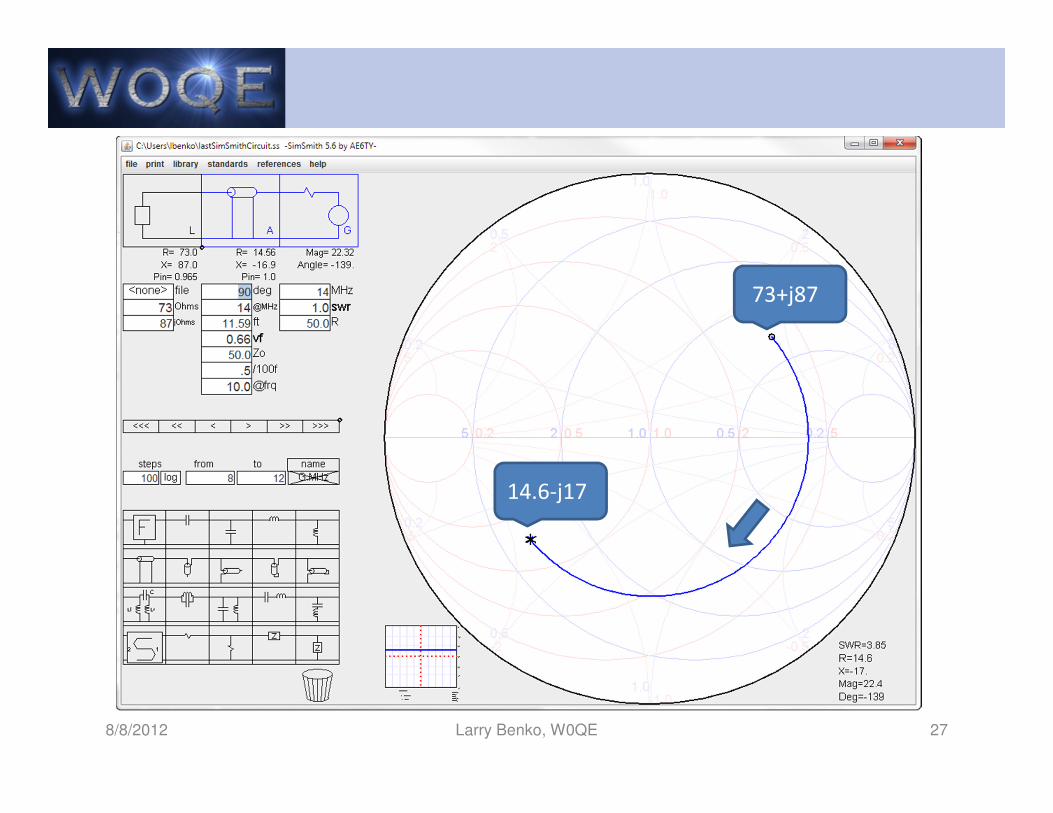
Reflection Examples
• Frequency = 14.0MHz, load = 73 + j87Ω, load
SWR = 4.0:1, & various lengths of RG-213
• 11.6’ (.25 λ) = 14.5 - j17.0 (Tx SWR = 3.85:1)
• 14’ = 13.1 – j1.2 (Tx SWR = 3.82:1)
• 25.8’ = 184.2 – j4.1 (Tx SWR = 3.68)
• 23.18’ (.5 λ) = 74.8 + j81.8 (Tx SWR = 3.71:1)
• 46.37’ (1 λ) = 76.1 + j76.8 (Tx SWR = 3.47:1)
• 200’ = 20.5 + j1.9 (Tx SWR = 2.44:1)
8/8/2012 Larry Benko, W0QE 26
8/8/2012 Larry Benko, W0QE 27
14.6-j17
73+j87
Loss
• At HF loss is predominantly due to the RF
resistance of the conductors and is incrementally
proportional to current squared
• Matched loss at HF is frequency dependent and
increases ~ as the square root of frequency
Loss(f2) ~= Loss(f1)*sqrt(f2/f1) dB.
• Following example shows losses with and
without matching for a 100W transmitter
8/8/2012 Larry Benko, W0QE 28
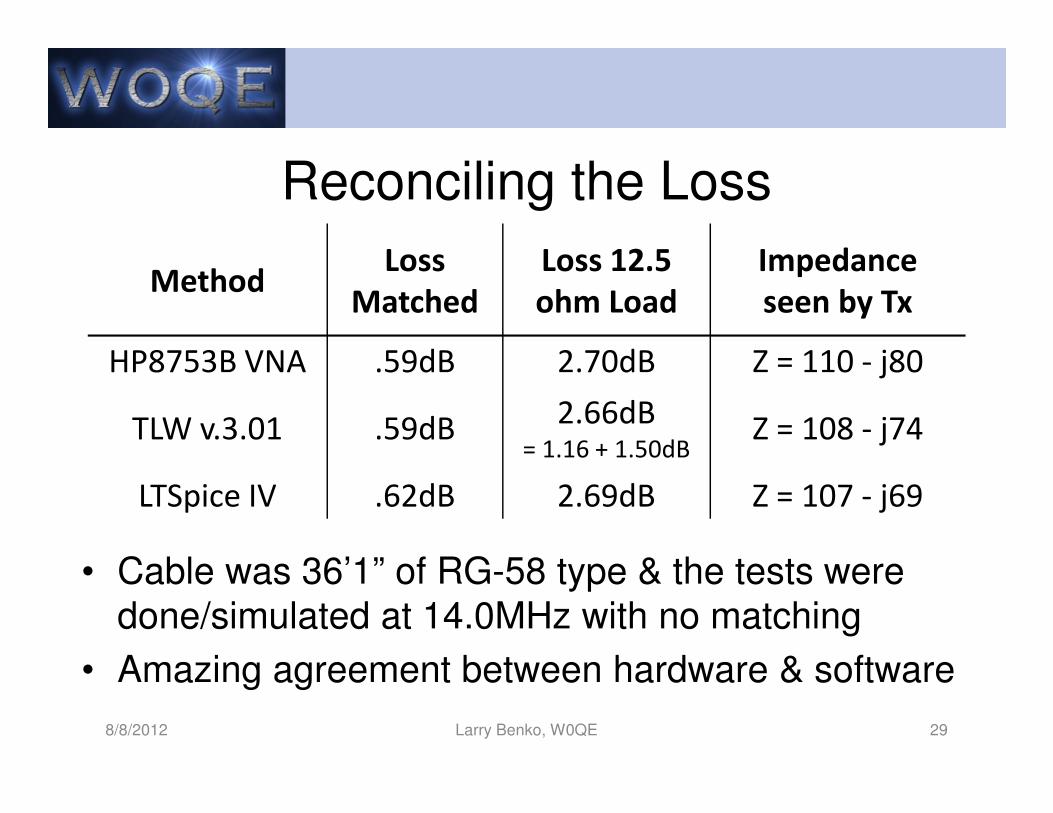
Reconciling the Loss
8/8/2012 Larry Benko, W0QE 29
• Cable was 36’1” of RG-58 type & the tests were
done/simulated at 14.0MHz with no matching
• Amazing agreement between hardware & software
MethodLoss
Matched
Loss 12.5
ohm Load
Impedance
seen by Tx
HP8753B VNA .59dB 2.70dB Z = 110 - j80
TLW v.3.01 .59dB2.66dB
= 1.16 + 1.50dBZ = 108 - j74
LTSpice IV .62dB 2.69dB Z = 107 - j69
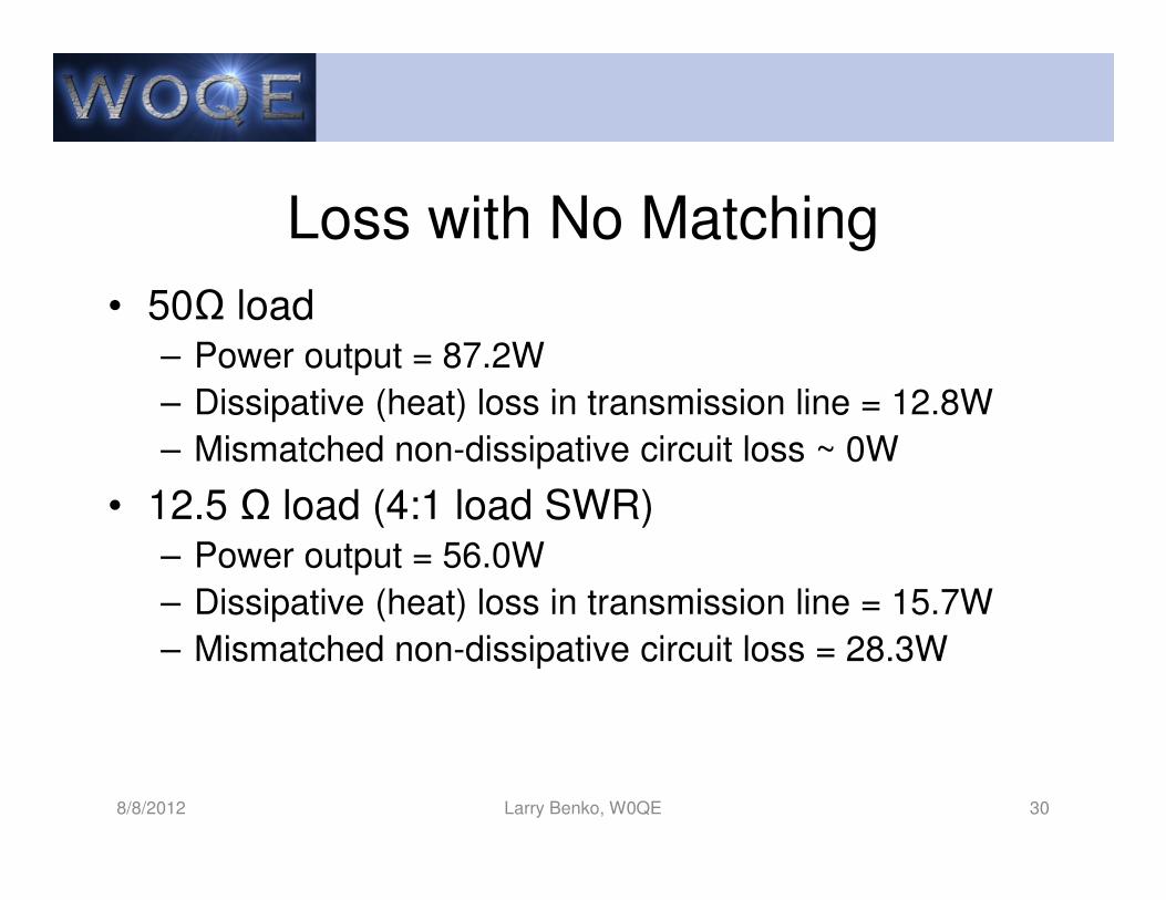
Loss with No Matching
• 50Ω load– Power output = 87.2W
– Dissipative (heat) loss in transmission line = 12.8W
– Mismatched non-dissipative circuit loss ~ 0W
• 12.5 Ω load (4:1 load SWR)– Power output = 56.0W
– Dissipative (heat) loss in transmission line = 15.7W
– Mismatched non-dissipative circuit loss = 28.3W
8/8/2012 Larry Benko, W0QE 30

Loss with Matching
• Matching at transmitter end of transmission line– 12.5 Ω load = 78.1W
– Dissipative loss in line = 21.9W
• Matching at load end of transmission line– 12.5 Ω load = 87.2W
– Dissipative loss in line = 12.8W
• Power output difference is 0.5dB between load &
source matching
• Higher SWRs and line loss increase deltas
8/8/2012 Larry Benko, W0QE 31
Overall Circuit Loss
• Dissipative loss in the transmission line– Increases with SWR and driving power
– Transmission line loss is primarily a function of the
square of the currents summed over length at HF
• Non-dissipative loss at source end due to
mismatch– Drive with impedance which is the conjugate match to
mismatched line to deliver max. power (antenna tuner)
– Reducing the mismatch loss via impedance matching
increases dissipative loss in line
8/8/2012 Larry Benko, W0QE 32
10:1 SWR Example
• 1λ RG-58A (Belden 8259) 46.368’ long @ 14.0MHz connected to a 5 + j0 Ω load with an optional tuner
at the antenna, in the shack, or no tuner at all
• Do calculation in both TLW & LTSpice showing
consistency in methods
• 0.87dB vs 3.10dB vs 5.68dB (82W vs 49W vs 27W)
for a 100W equivalent transmitter not including any
SWR power foldback
8/8/2012 Larry Benko, W0QE 33
Options to the Previous Example
• RG-58A :0.87dB vs 3.10dB vs 5.68dB
• RG-213: 0.36dB vs 1.54dB vs 5.17dB
• LMR-500: 0.16dB vs 0.74dB vs 4.95dB
• 4:1 xfmr (.2dB loss) @ antenna (SWR=2.5:1):
N/A vs 1.38dB vs 1.95dB
• RG-213 + 4:1 xfmr (.2dB) @ antenna:
N/A vs 0.71dB vs 1.44dB
• Many other choices
8/8/2012 Larry Benko, W0QE 34
Measuring Line Zo and Loss
• Measuring surge impedance (Zo)– Open far end of line, measure Z1 @ phase angle A1
– Short far end of line, measure Z2 @ phase angle A2
– Zo = square root (Z1 * Z2) @ phase angle (A1 + A2)/2
– Usually resultant phase is close to zero
• Measuring Loss– Open far end of line, measure return loss RL1
– Short far end of line, measure return loss RL2
– Loss ~= ( RL1 + RL2 )/4
8/8/2012 Larry Benko, W0QE 35
Shielding in Transmission Lines
• At every point currents are equal and out of phase
resulting in very little radiation and pickup
• Coaxial transmission line currents are on the
outside of the center conductor and inside of shield
• Current on the outside of the coax does affect the
currents on the inside very minimally & vice versa
• Currents on the outside of the shield do radiate
8/8/2012 Larry Benko, W0QE 36
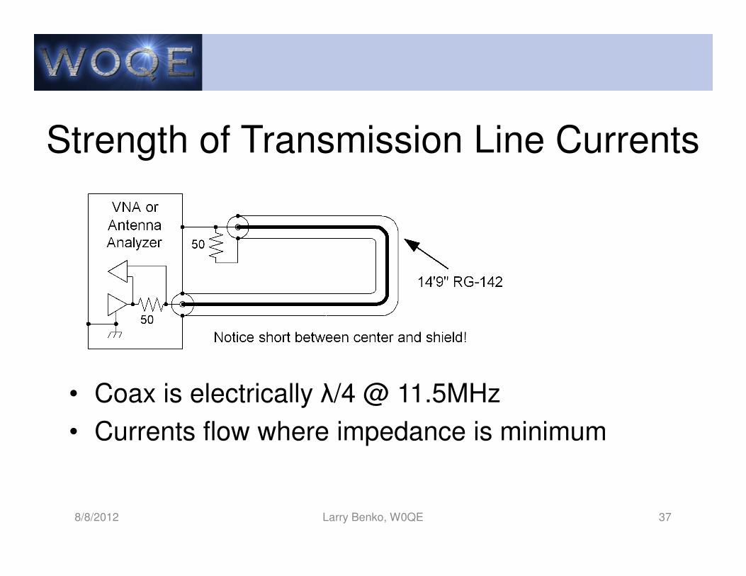
Strength of Transmission Line Currents
• Coax is electrically λ/4 @ 11.5MHz
• Currents flow where impedance is minimum
8/8/2012 Larry Benko, W0QE 37
8/8/2012 Larry Benko, W0QE 38
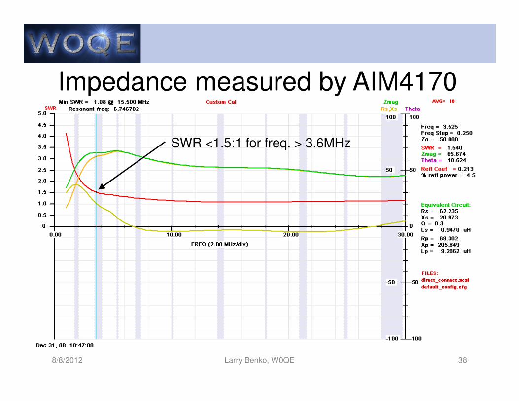
Impedance measured by AIM4170
SWR <1.5:1 for freq. > 3.6MHz
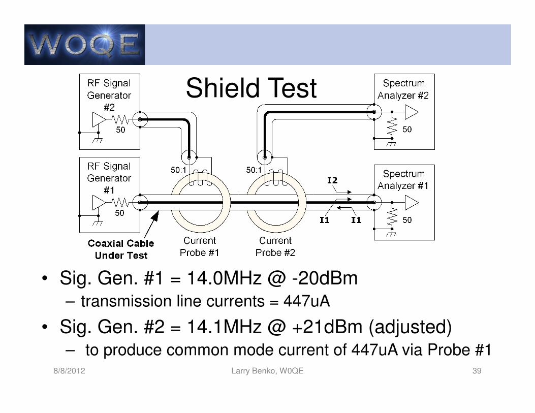
• Sig. Gen. #1 = 14.0MHz @ -20dBm– transmission line currents = 447uA
• Sig. Gen. #2 = 14.1MHz @ +21dBm (adjusted)– to produce common mode current of 447uA via Probe #1
8/8/2012 Larry Benko, W0QE 39
Shield Test
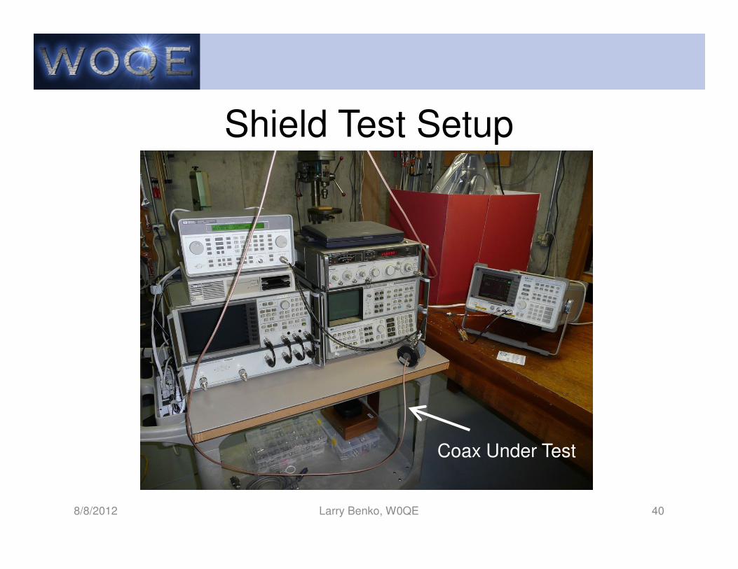
Shield Test Setup
8/8/2012 Larry Benko, W0QE 40
Coax Under Test
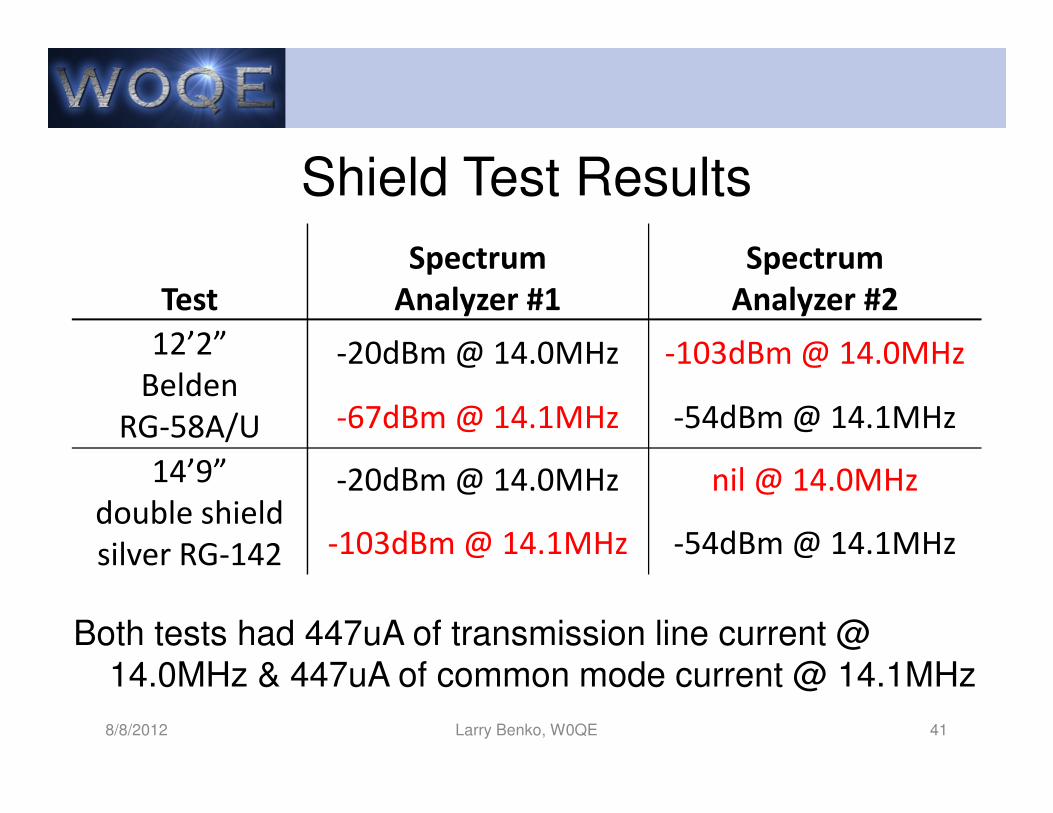
Shield Test Results
Both tests had 447uA of transmission line current @ 14.0MHz & 447uA of common mode current @ 14.1MHz
8/8/2012 Larry Benko, W0QE 41
Test
Spectrum
Analyzer #1
Spectrum
Analyzer #2
12’2”
Belden
RG-58A/U
-20dBm @ 14.0MHz -103dBm @ 14.0MHz
-67dBm @ 14.1MHz -54dBm @ 14.1MHz
14’9”
double shield
silver RG-142
-20dBm @ 14.0MHz nil @ 14.0MHz
-103dBm @ 14.1MHz -54dBm @ 14.1MHz
Transmission Line Conclusion
• Was level of material appropriate?
• Follow up with impedance matching
• Other topics such as troubleshooting, phasing,
and transmission line transformers
8/8/2012 Larry Benko, W0QE 42


![Novel Transmission Lines for Si MZI Modulators · [6,7], polymer modulators [8], and strained silicon modulators based on the non-linear χ(2)%effect [9,10]. Amongst the aforementioned](https://static.fdocument.org/doc/165x107/5f756e0b8813075ef6637495/novel-transmission-lines-for-si-mzi-67-polymer-modulators-8-and-strained.jpg)