
ULTRASONIC TREATMENT WITH NICKEL ELECTROPLATING COMBINED WITH OXIDATION
51
ULTRASONIC TREATMENT WITH NICKEL ELECTROPLATING COMBINED WITH OXIDATION FOR DEVELOPING γ-Al 2 O 3 WASHCOAT ON Fe-Cr-Al SUBSTRATE ADE FIRDIANTO A thesis submitted in fulfillment of the requirement for the award of the Degree of Master of Mechanical Engineering Faculty of Mechanical and Manufacturing Engineering Universiti Tun Hussein Onn Malaysia FEBRUARY 2012
Transcript of ULTRASONIC TREATMENT WITH NICKEL ELECTROPLATING COMBINED WITH OXIDATION
ULTRASONIC TREATMENT WITH NICKEL ELECTROPLATING COMBINED
WITH OXIDATION FOR DEVELOPING γ-Al2O3 WASHCOAT ON Fe-Cr-Al
SUBSTRATE
ADE FIRDIANTO
A thesis submitted in fulfillment of the requirement for the award of the
Degree of Master of Mechanical Engineering
Faculty of Mechanical and Manufacturing Engineering
Universiti Tun Hussein Onn Malaysia
FEBRUARY 2012
v
ABSTRACT
Fe-Cr-Al is used as metallic support for catalytic converter due to its high thermal
conductivity, lower heat capacity, high temperature and mechanical shock resistance.
γ-Al2O3 is the most widely used material as washcoat which embedded on metallic
support for the catalytic converter application. The problem is the coating adhesion
between the metallic support and the ceramic washcoat becomes a problem in long-
term high temperature oxidation. On the other hand, the gamma phase of alumina
will be transformed to alpha phase at high temperature. The ultrasonic technique via
cavitation bubbles and high velocity can make surface deformation and also
accelerate the γ-Al2O3 powders to bombardment occurred on the Fe-Cr-Al surface.
This process generates sufficiently heat and γ-Al2O3 layer can be formed on the Fe-
Cr-Al surface. Subsequently, electroplating process embeds the nickel and also can
strengthen the adhesion when oxidized. Therefore, this work presents the ultrasonic
treatment with nickel electroplating for developing γ-Al2O3 washcoat on Fe-Cr-Al
substrate and oxidation treatment for catalytic converter application. Washcoat layer
on Fe-Cr-Al was prepared by using γ-Al2O3 powders through ultrasonic treatment.
Catalyst material was prepared by using nickel electroplating. The oxidation kinetics
was conducted at temperatures of 500, 700, 900 and 1100 oC in air for 100 hours.
The surface morphology, cross section analysis, chemical composition, elemental
maps and phase structure of coated Fe-Cr-Al were analyzed by Scanning Electron
Microscope (SEM), Energy Dispersive X-ray Spectroscopy (EDS) and X-ray
Diffraction (XRD) respectively. The results showed that the surface of Fe-Cr-Al
contained γ-Al2O3 powders after ultrasonic treatment. The layer of alumina oxide has
been formed on coated Fe-Cr-Al and no spallation occurred after oxidation. It is
prove that γ-Al2O3 washcoat and NiO as a catalyst have successfully embedded on
Fe-Cr-Al substrate by ultrasonic treatment combined with nickel electroplating at
long term high temperature oxidation that enhance the adhesive properly.
vi
ABSTRAK
Fe-Cr-Al digunakan sebagai sokongan logam untuk penukar bermangkin. Secara
umumnya, γ-Al2O3 adalah bahan yang digunakan sebagai washcoat yang dilekatkan
pada sokongan logam untuk aplikasi penukar bermangkin. Masalahnya ialah, lekatan
lapisan antara sokongan logam dan seramik washcoat menjadi masalah dalam
pengoksidaan suhu tinggi bagi satu jangka masa yang lama. Selain daripada itu, fasa
gamma alumina akan mengalami transformasi ke alpha pada suhu tinggi. Teknik
ultrasonik melalui gelembung kaviti dan kelajuan tinggi akan menyebabkan
deformasi permukaan dan juga boleh mempercepatkan serbuk γ-Al2O3 menyentuh
permukaan Fe-Cr-Al. Proses ini menghasilkan haba yang mencukupi dan lapisan γ-
Al2O3 boleh terbentuk pada permukaan Fe-Cr-Al. Disamping melekatkan nikel,
proses penyaduran juga boleh menguatkan lekatan ketika dioksida. Oleh kerana itu
dalam kajian ini, kaedah rawatan ultrasonik dengan penyaduran nikel untuk
pengembangan γ-Al2O3 sebagai washcoat pada substrat Fe-Cr-Al dan rawatan
pengoksidaan untuk aplikasi penukar bermangkin. Lapisan washcoat pada Fe-Cr-Al
disusun dengan menggunakan serbuk γ-Al2O3 melalui kaedah rawatan ultrasonik.
Bahan pemangkin disediakan dengan menggunakan nikel melalui proses penyaduran.
Pengoksidaan dilakukan di antara suhu 500, 700, 900 dan 1100 oC di udara selama
100 jam. Morfologi permukaan, keratan rentas, komposisi kimia, pemetaan elemen
dan struktur fasa dianalisis menggunakan Scanning Electron Microscope (SEM),
Energy Dispersive X-ray Spectroscopy (EDS) dan X-ray Diffraction (XRD).
Keputusan yang diperolehi menunjukkan bahawa pada permukaan Fe-Cr-Al
mengandungi lapisan serbuk γ-Al2O3 selepas rawatan ultrasonik. Lapisan alumina
oksida terbentuk pada permukaan Fe-Cr-Al dan pengelupasan tidak berlaku selepas
pengoksidaan. Ini membuktikan bahawa washcoat γ-Al2O3 dan NiO sebagai
pemangkin berjaya melekat pada substrat Fe-Cr-Al melalui rawatan ultrasonik yang
digabungkan dengan penyaduran nikel pada pengoksidaan suhu tinggi bagi jangka
masa yang lama dan dapat meningkatkan lekatan dengan baik.
vii
CONTENTS
TITLE i
DECLARATION ii
DEDICATION iii
ACKNOWLEDGEMENT iv
ABSTRACT v
CONTENTS vii
LIST OF TABLES xiii
LIST OF FIGURES xiv
LIST OF SYMBOLS AND ABBREVIATIONS xx
LIST OF APPENDIX xxiv
CHAPTER 1 INTRODUCTION 1
1.1 Background of Study 1
1.2 Problem Statements 3
viii
1.3 Hypothesis 4
1.4 Aim of Study 4
1.5 Objective of Study 4
1.6 Scope of Study 5
CHAPTER 2 LITERATURE REVIEW 6
2.1 Catalytic Converter 6
2.1.1 Substrate 8
2.1.1.1 Metallic Substrate 9
2.1.1.2 Fe-Cr-Al Metallic Substrate 11
2.2 Washcoat 12
2.2.1 Al2O3 Washcoat 13
2.3 Particle Size Distribution of the Carrier/Washcoat 15
2.4 Washcoat Development on Fe-Cr-Al Metallic Substrate 16
2.5 Catalyst Material for Catalytic Converter 18
2.5.1 Nickel as Catalyst Material 18
ix
2.6 Ultrasonic Surface Treatment 19
2.6.1 Reactions Involving Metal or Solid Surfaces 20
2.6.2 Reactions Involving Powders or Other Particulate Matter 20
2.7 Acoustic Cavitation 21
2.7.1 Cavitation Near a Surface 22
2.7.2 Heterogeneous Powder Liquid Reactions 23
2.8 Nickel Electroplating 25
2.8.1 Basic Process of Electrodeposition 25
2.8.2 Sulphamate Nickel Electroplating Solutions 27
2.8.3 Average Coating Coverage 28
2.9 Oxidation of Fe-Cr-Al Coating 29
2.9.1 Wagner’s Oxidation Theory 30
2.9.2 Oxidation Related to Catalytic Materials 32
2.9.3 Transient Behaviour Associated with Alumina Phase
Transformations 34
x
CHAPTER 3 METHODOLOGY 36
3.1 Catalysis Material and Substrate 36
3.2 Material Preparation 37
3.2.1 Ultrasonic Treatment of γ-Al2O3 Powder 37
3.2.2 Particle Size Analysis and Distribution of γ-Al2O3 After
Sonicated by Ultrasonic Clamp-on Tubular Reactor 38
3.3 Experimental Procedures 40
3.3.1 Ultrasonic Treatment of Fe-Cr-Al Foils mixed
with γ-Al2O3 Powder 40
3.3.2 Nickel Electroplating 41
3.3.3 Oxidation of Coated Fe-Cr-Al 43
3.4 Characterization 43
3.4.1 Scanning Electron Miroscopy (SEM) and
Energy Dispersive X-ray Spectroscopy (EDS) 45
3.4.2 X-ray Diffraction (XRD) 46
xi
CHAPTER 4 RESULT AND DISCUSSION 49
4.1 Effect of Ultrasonic Treatment Period on the γ-Al2O3
Powder in Term of Particle Size and Distribution 49
4.1.1 Microstructure Observation of γ-Al2O3 Powder Pre
and Post Ultrasonic Treatment 52
4.1.2 Phase Analysis of γ-Al2O3 After Ultrasonic Treatment 55
4.2 Distribution of γ-Al2O3 Powder on Fe-Cr-Al Surface
After Ultrasonic Treatment 56
4.3 Oxidation of coated Fe-Cr-Al 58
4.3.1 Weight Gain of coated Fe-Cr-Al 58
4.3.2 Comparison of Weight Gain of Coated Fe-Cr-Al
by Ultrasonic Treatment with γ-Al2O3 and Al2O3
Oxidized at 900 oC and 1100
oC 61
4.3.2.1 Comparison of Weight Gain of Coated Fe-Cr-Al
by Ultrasonic Treatment with γ-Al2O3 and Al2O3
Oxidized at 900 oC for 100 Hours 62
4.3.2.2 Comparison of Weight Gain of Coated Fe-Cr-Al
by Ultrasonic Treatment with γ-Al2O3 and Al2O3
Oxidized at 1100 oC for 100 Hours 66
4.3.3 Parabolic Rate Constant (kp) of coated Fe-Cr-Al 71
xii
4.4 Phase analysis of Coated Fe-Cr-Al After Oxidation
at Temperatures of 500, 700, 900 and 1100 oC 75
4.5 Surface Morphology of Coated Fe-Cr-Al After
Oxidation at Temperatures of 500, 700, 900
and 1100 oC 77
4.6 Cross-section and EDS Chemical Analysis of γ-Al2O3
Washcoat on Fe-Cr-Al After Oxidation
at Temperature of 900 oC and 1100
oC 85
CHAPTER 5 CONCLUSION AND FUTURE WORK 89
5.1 Conclusion 89
5.2 Future Work 90
REFERENCES 91
APPENDICES 97
VITA
xiii
LIST OF TABLES
2.1 Typical composition of electroplating solutions
and electroplating parameter 27
2.2 Time to electrodeposit nickel at various current
densities 29
3.1 Chemical composition (wt.%) of Fe-Cr-Al foil 36
3.2 Process condition for clamp-on tubular reactor 38
3.3 Fe-Cr-Al treatment conditions 40
3.4 Chemical composition of electrolyte 42
4.1 Parabolic rate constant (kp) of all coated Fe-Cr-Al
after oxidation at range of 500 oC to 1100
oC 74
4.2 EDS composition point (01, 02 and 03) analysis data
at 900 oC 86
4.3 EDS composition point (01, 02 and 03) analysis data
at 1100 oC 87
xiv
LIST OF FIGURES
1.1 The focused area on washcoat and catalyst
development for catalytic converter 3
2.1 Structure of catalytic converter 7
2.2 Parameters affecting on the catalyst performance 8
2.3 The design of metallic monolith substrate 11
2.4 Schematic diagram for catalytic sites dispersed
on a high surface area of Al2O3 carrier bonded to
a monolith support 13
2.5 (a) Scanning electron microscope (SEM) image
of gamma (γ-Al2O3), (b) SEM of alpha (α-Al2O3) 14
2.6 Particle size measurement using CILAS particle
size analyzer (PSA) 16
2.7 Generation of an acoustic bubble 22
2.8 Cavitation bubble collapse at or near a solid surface 23
2.9 Acoustic cavitation in a liquid with a suspended
powder 24
2.10 Cavitation effects in a heterogeneous liquid system 24
2.11 Basic electrical circuit for electroplating 25
2.12 Schematic process for the protective oxide scale
during the initial and transient oxidation stage 30
2.13 Hypothetical mass-gain versus time curve for
an oxidation reaction 31
2.14 The temperature profile of inlet/outlet gas and
substrate for 500 second test cycle 32
2.15 A variation of Al2O3 transformation temperature
on bulk material used for catalyst supports
(a) γ-Al2O3 + 3% Pt (b) γ-Al2O3 34
xv
3.1 Equipment of ultrasonic clamp-on tubular reactor 37
3.2 CILAS 1180 particles size analyzer 38
3.3 Schematic diagram of CILAS 1180 particle size
analyzer work 39
3.4 Schematic diagram of ultrasonic treatment process
using laborette 17 ultrasonic cleaning bath 41
3.5 Schematic diagram of electroplating process 42
3.6 Cyclic oxidation of coated Fe-Cr-Al at temperature
of 900 oC for 100 hours. Similar cyclic approaches
were applied to 500, 700 and 1100 oC 43
3.7 (a) Hand grinder instrument and (b) polishing
machine 44
3.8 Scanning Electron Microscopy (SEM) attached
with Energy Dispersive X-ray Spectroscopy (EDS) 45
3.9 X-ray Diffraction (XRD) Bruker D8-Advance 46
3.10 The conditions required for constructive
interference determined by Bragg’s Law 47
3.11 Notation of lattice points, rows and planes 48
4.1 Particles size and distribution of raw material
γ-Al2O3 powder 50
4.2 Particles size and distribution of γ-Al2O3 powder
after ultrasonic for 10 minutes 50
4.3 Particles size and distribution of γ-Al2O3 powder
after ultrasonic for 20 minutes 51
4.4 Particles size and distribution of γ-Al2O3 powder
after ultrasonic for 30 minutes 52
4.5 SEM image of raw material γ-Al2O3 powders 53
4.6 SEM image of γ-Al2O3 powders after ultrasonic
for 10 minutes 53
xvi
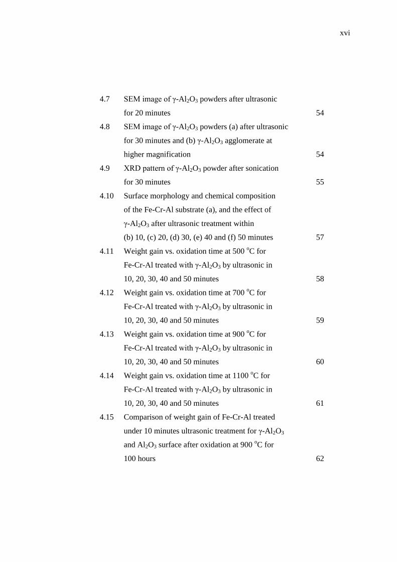
4.7 SEM image of γ-Al2O3 powders after ultrasonic
for 20 minutes 54
4.8 SEM image of γ-Al2O3 powders (a) after ultrasonic
for 30 minutes and (b) γ-Al2O3 agglomerate at
higher magnification 54
4.9 XRD pattern of γ-Al2O3 powder after sonication
for 30 minutes 55
4.10 Surface morphology and chemical composition
of the Fe-Cr-Al substrate (a), and the effect of
γ-Al2O3 after ultrasonic treatment within
(b) 10, (c) 20, (d) 30, (e) 40 and (f) 50 minutes 57
4.11 Weight gain vs. oxidation time at 500 oC for
Fe-Cr-Al treated with γ-Al2O3 by ultrasonic in
10, 20, 30, 40 and 50 minutes 58
4.12 Weight gain vs. oxidation time at 700 oC for
Fe-Cr-Al treated with γ-Al2O3 by ultrasonic in
10, 20, 30, 40 and 50 minutes 59
4.13 Weight gain vs. oxidation time at 900 oC for
Fe-Cr-Al treated with γ-Al2O3 by ultrasonic in
10, 20, 30, 40 and 50 minutes 60
4.14 Weight gain vs. oxidation time at 1100 oC for
Fe-Cr-Al treated with γ-Al2O3 by ultrasonic in
10, 20, 30, 40 and 50 minutes 61
4.15 Comparison of weight gain of Fe-Cr-Al treated
under 10 minutes ultrasonic treatment for γ-Al2O3
and Al2O3 surface after oxidation at 900 oC for
100 hours 62
xvii
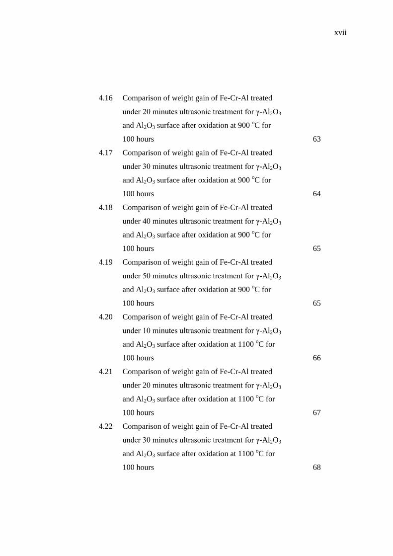
4.16 Comparison of weight gain of Fe-Cr-Al treated
under 20 minutes ultrasonic treatment for γ-Al2O3
and Al2O3 surface after oxidation at 900 oC for
100 hours 63
4.17 Comparison of weight gain of Fe-Cr-Al treated
under 30 minutes ultrasonic treatment for γ-Al2O3
and Al2O3 surface after oxidation at 900 oC for
100 hours 64
4.18 Comparison of weight gain of Fe-Cr-Al treated
under 40 minutes ultrasonic treatment for γ-Al2O3
and Al2O3 surface after oxidation at 900 oC for
100 hours 65
4.19 Comparison of weight gain of Fe-Cr-Al treated
under 50 minutes ultrasonic treatment for γ-Al2O3
and Al2O3 surface after oxidation at 900 oC for
100 hours 65
4.20 Comparison of weight gain of Fe-Cr-Al treated
under 10 minutes ultrasonic treatment for γ-Al2O3
and Al2O3 surface after oxidation at 1100 oC for
100 hours 66
4.21 Comparison of weight gain of Fe-Cr-Al treated
under 20 minutes ultrasonic treatment for γ-Al2O3
and Al2O3 surface after oxidation at 1100 oC for
100 hours 67
4.22 Comparison of weight gain of Fe-Cr-Al treated
under 30 minutes ultrasonic treatment for γ-Al2O3
and Al2O3 surface after oxidation at 1100 oC for
100 hours 68
xviii
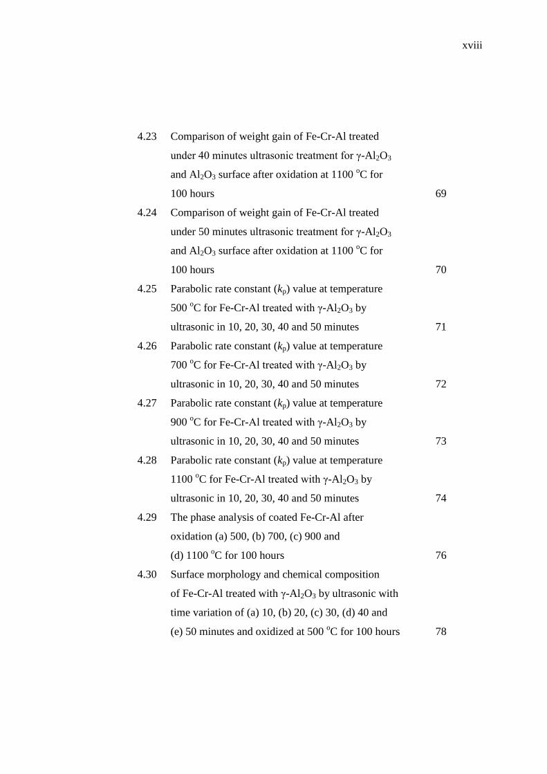
4.23 Comparison of weight gain of Fe-Cr-Al treated
under 40 minutes ultrasonic treatment for γ-Al2O3
and Al2O3 surface after oxidation at 1100 oC for
100 hours 69
4.24 Comparison of weight gain of Fe-Cr-Al treated
under 50 minutes ultrasonic treatment for γ-Al2O3
and Al2O3 surface after oxidation at 1100 oC for
100 hours 70
4.25 Parabolic rate constant (kp) value at temperature
500 oC for Fe-Cr-Al treated with γ-Al2O3 by
ultrasonic in 10, 20, 30, 40 and 50 minutes 71
4.26 Parabolic rate constant (kp) value at temperature
700 oC for Fe-Cr-Al treated with γ-Al2O3 by
ultrasonic in 10, 20, 30, 40 and 50 minutes 72
4.27 Parabolic rate constant (kp) value at temperature
900 oC for Fe-Cr-Al treated with γ-Al2O3 by
ultrasonic in 10, 20, 30, 40 and 50 minutes 73
4.28 Parabolic rate constant (kp) value at temperature
1100 oC for Fe-Cr-Al treated with γ-Al2O3 by
ultrasonic in 10, 20, 30, 40 and 50 minutes 74
4.29 The phase analysis of coated Fe-Cr-Al after
oxidation (a) 500, (b) 700, (c) 900 and
(d) 1100 oC for 100 hours 76
4.30 Surface morphology and chemical composition
of Fe-Cr-Al treated with γ-Al2O3 by ultrasonic with
time variation of (a) 10, (b) 20, (c) 30, (d) 40 and
(e) 50 minutes and oxidized at 500 oC for 100 hours 78

xix
4.31 Surface morphology and chemical composition
of Fe-Cr-Al treated with γ-Al2O3 by ultrasonic with
time variation of (a) 10, (b) 20, (c) 30, (d) 40 and
(e) 50 minutes and oxidized at 700 oC for 100 hours 80
4.32 Surface morphology and chemical composition
of Fe-Cr-Al treated with γ-Al2O3 by ultrasonic with
time variation of (a) 10, (b) 20, (c) 30, (d) 40 and
(e) 50 minutes and oxidized at 900 oC for 100 hours 82
4.33 Surface morphology and chemical composition
of Fe-Cr-Al treated with γ-Al2O3 by ultrasonic with
time variation of (a) 10, (b) 20, (c) 30, (d) 40 and
(e) 50 minutes and oxidized at 1100 oC for 100 hours 84
4.34 Lateral cross-section analysis of coated Fe-Cr-Al
at 900 oC 85
4.35 Lateral cross-section analysis of coated Fe-Cr-Al
at 1100 oC 86
4.36 EDS elemental maps analysis at lateral view of
γ-Al2O3 layer on coated Fe-Cr-Al at 900 oC 87
4.37 EDS elemental maps analysis at lateral view of
γ-Al2O3 layer on coated Fe-Cr-Al at 1100 oC 88
xx
LIST OF SYMBOLS AND ABBREVIATIONS
Al2O3 - Aluminum Oxide
Fe-Cr-Al - Iron-Chromium-Aluminium
oC - Degree Celsius
NiO - Nickel Oxide
CO - Carbon monoxide
NOx - Nitrogen Oxide
HC - Hydrocarbons
% - Percent
kp - Parabolic Rate Contant
N2 - Nitrogen
CO2 - Carbon Dioxide
H2O - Dihydrogen Monoxide (Water)
O2 - Oxygen
μm - Micrometer
cm - Centimeter
mm - Millimeter
mil - Mile
cpsi - Cells Per Square Inch
inch - Inchies
α - Alpha
γ - Gamma
θ - Theta
δ - Delta
η - Eta
wt - Weight
Al - Aluminum
RE - Reactive Element
xxi
Mg - Magnesium
Mo - Molybdenum
Mn - Manganese
Co - Cobalt
Cu - Copper
Zr - Zirconium
Y - Yittrium
Ce - Cerium
La - Lanthanium
Hf - Hafnium
m2 - Meter Square
g - Gram
µ - Micron
Ni - Nickel
Pt - Platinum
Pd - Palladium
Rh - Rhodium
H2S - Hydrogen Sulfide
Hz - Hertz
kHz - Kilohertz
MHz - Megahertz
K - Mass Transfer Coefficient
A - Surface Area
T - Average Thickness
I - Current
t - Time
dm2 - Decimeter Square
Wt - Weight After Oxidation
Wo - Initial Weight
W(t) - Weight Gain
xxii
J - Current Density
W - Watt
V - Volt
kg - Kilogram
L - Liter
HCl - Hydrochloric Acid
NaOH - Sodium Hydroxide
Ni(SO3NH2)2 4H2O - Nickel Sulphamate
NiCl 6H2O - Nickel Chloride
H2BO3 - Boric Acid
C12H25SO4Na - Sodium Lauryal Sulphate
A - Ampere
SiC - Silicon Carbide
Q3 - Cummulative Value
q3 - Population Density
x - Particle Diameter
C - Carbon
min - Minutes
h - Hour
ASTM - American Society For Testing and Materials
BES - Back Scattered
EBSD - Electron Backscattered Diffraction
EDS - Energy Dispersive X-ray Spectroscopy
EPA - Environmental Protection Agency
GSA - Geometrical Surface Area
LEV II - Low Emission Vehicle II
PSA - Particle Size Analyzer
PSD - Particle Size Distribution
SEM - Scanning Electron Microscopy
SET - Single Electron Transfer

xxiii
TWC - Three-Way Catalyst
VOCs - Volatile Organic Compounds
XRD - X-ray Diffraction
xxiv
LIST OF APPENDICES
APPENDIX TITLE PAGE
A Generator Specification of Ultrasonic Clamp-On
Tubular Reactor 97
B Flowchart of Research Methodology 98
C Particle Size Analyzer Data 99
D Weight Gain Data 109
E List of Publications 111
CHAPTER 1
INTRODUCTION
In this chapter, the background of this research will be explained in detail which
consists of research background, problem statement, hypothesis, aim, objective and
scope of study.
1.1 Background of study
Air pollution caused by cars is one of the most challenging problems that contribute
to the environment problem. By-products of the operation of the gasoline engine
include carbon monoxide (CO), oxides of nitrogen (NOx), and unburned fuel
compounds is hydrocarbons (HC), each of which is a pollutant (George, 2006). It is
known that exhaust gas emissions from the vehicles can cause serious problems for
human health and greenhouse effect that could endanger the world. Many
automotive industries and research institutes have tried to develop catalytic converter
technology (Zhao et al., 2003).
The catalytic converter is a device incorporated into the exhaust system of an
automobile that reduces the amount of pollutants in the automobile's exhaust gases.
The centerpiece of this technology based on to the three-way catalyst (TWC) used on
gasoline spark-ignited vehicles in all major world markets today. The name “three-
way catalyst” was applied to catalytic controls that capable of reducing all three
criteria pollutants such as, carbon monoxide (CO), oxides of nitrogen (NOx), and
volatile organic compounds (VOCs). The three-way catalytic converter (TWC) has
been the primary emission control technology on light-duty gasoline vehicles since
the early 1980 (Kubsh, 2006). This device is located in-line with the exhaust system
2
and used to cause a desirable chemical reaction to take place in the exhaust flow.
Today, more than 90% of the new automobiles sold around the world are equipped
with catalytic converters.
The regulatory programs have been continually pushed to lower levels in
response to air quality concerns. California was adopted Low Emission Vehicle II
(LEV II) program in late 1998, followed by Environmental Protection Agency (EPA)
finalizing the Tier 2 regulations in December 1999, Europe (Euro 3 and Euro 4
regulations), Japan (Japan Low Emission Vehicle regulations) and Korea (Korea
Low Emission Vehicle regulations). Emission regulations for new vehicles based on
the use of three-way catalyst technologies are now being implemented in almost
every world market, including large emerging markets in India and China (Kubsh,
2006).
Fe-Cr-Al foils become the most popular material than ceramics in the
fabrication of catalytic converter monolith due to it advantages for high temperature
resistance. Fe-Cr-Al also easily manufactured as honeycomb substrate with thinner
walls, so that obtain a lower pressure drop and higher contact surface area (Wu et al.,
2005). Fe-Cr-Al was mentioned that the corrugated and spiral shaped tools have
been successfully designed and developed for manufacturing the hand-made catalytic
converter in full scale size (Fahrul et al., 2009). The washcoat developments usually
use deposition technique such as a precipitation and dip-coating method (Valentini et
al., 2001), by impregnation method (Betta, 1997), or electroplating method
(Sebayang et al., 2010). The most widely used material in the application of
washcoat is γ-Al2O3. γ-Al2O3 has a large surface area, good pore size distribution,
surface acidic properties, composition of trace components and crystal structure
(Heck et al., 2009). Particles size influences the surface area on washcoat with the
smaller of particle size increase the surface area compared with large particles in the
same amount and that could affect the quality of washcoat (Ghosh et al., 2008). The
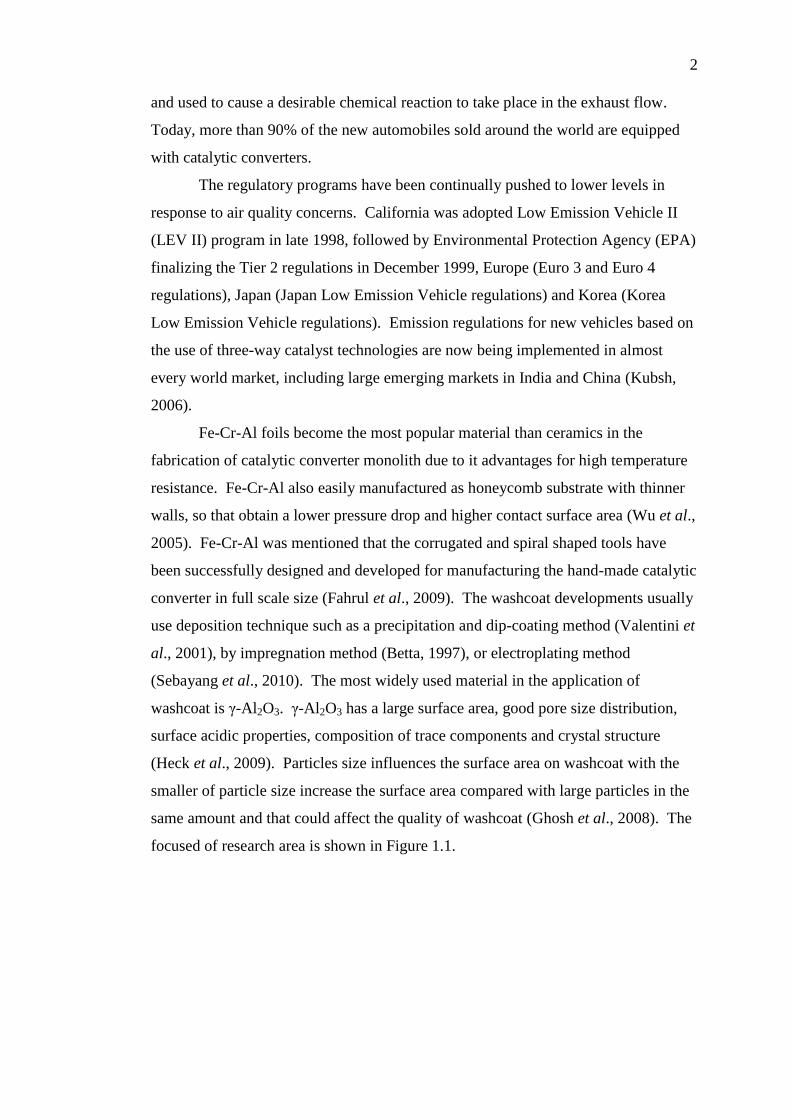
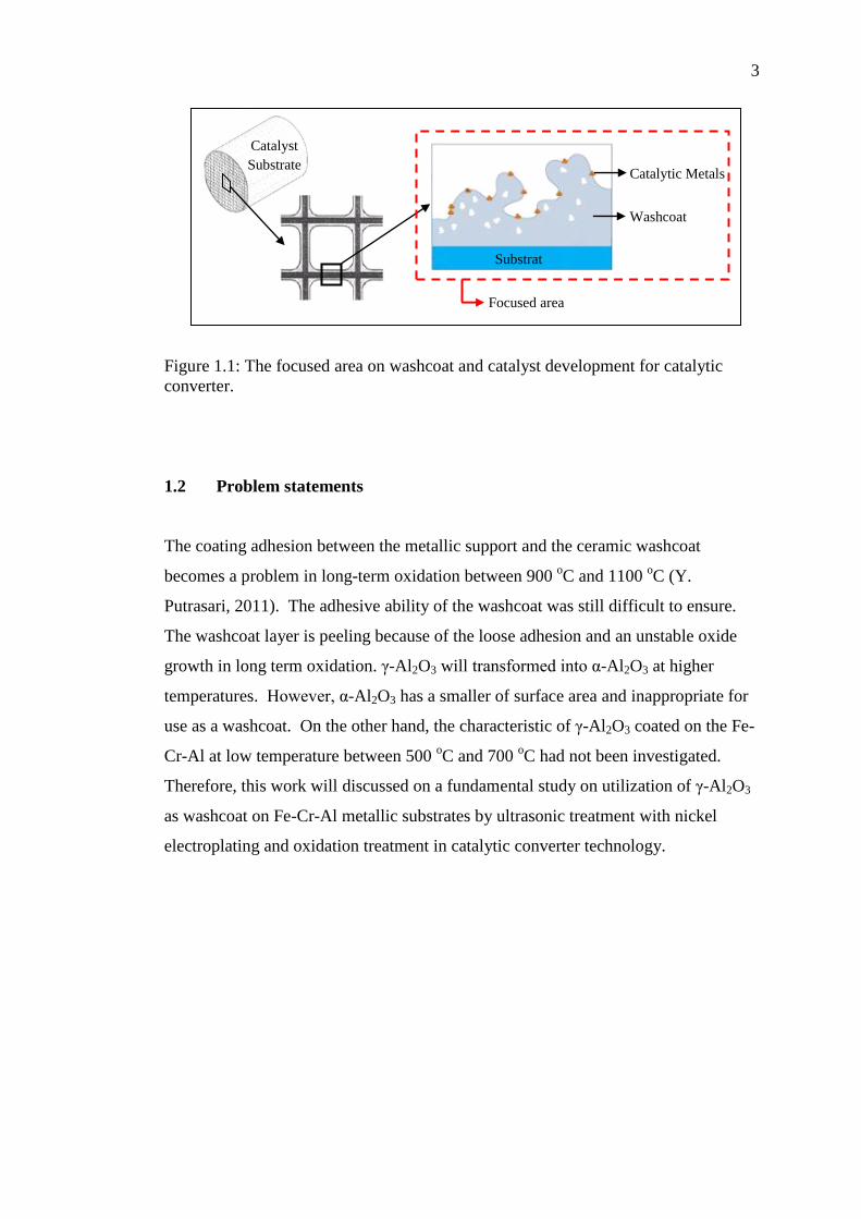
focused of research area is shown in Figure 1.1.
3
Figure 1.1: The focused area on washcoat and catalyst development for catalytic
converter.
1.2 Problem statements
The coating adhesion between the metallic support and the ceramic washcoat
becomes a problem in long-term oxidation between 900 oC and 1100
oC (Y.
Putrasari, 2011). The adhesive ability of the washcoat was still difficult to ensure.
The washcoat layer is peeling because of the loose adhesion and an unstable oxide
growth in long term oxidation. γ-Al2O3 will transformed into α-Al2O3 at higher
temperatures. However, α-Al2O3 has a smaller of surface area and inappropriate for
use as a washcoat. On the other hand, the characteristic of γ-Al2O3 coated on the Fe-
Cr-Al at low temperature between 500 oC and 700
oC had not been investigated.
Therefore, this work will discussed on a fundamental study on utilization of γ-Al2O3
as washcoat on Fe-Cr-Al metallic substrates by ultrasonic treatment with nickel
electroplating and oxidation treatment in catalytic converter technology.
Catalyst
Substrate
Washcoat
Catalytic Metals
Substrat
e
Focused area
4
1.3 Hypothesis
The ultrasonic technique via cavitation bubbles and high velocity can make the
surface deformation and also can accelerate the γ-Al2O3 powders, so that it can
bombardment to the Fe-Cr-Al surface. These collisions generate sufficient heat and
γ-Al2O3 layer can form on the Fe-Cr-Al surface. Electroplating process in addition is
to embed the nickel and strengthen the adhesion when oxidized. The expected
outcomes are the layer of γ-Al2O3 and nickel will embed on the Fe-Cr-Al metallic
substrates. The combination of oxide of γ-Al2O3 and NiO can be able to grow and
provide oxidation resistance on coated Fe-Cr-Al in long-term oxidation in range of
500, 700, 900 and 1100 oC for 100 hours. The utilization of γ-Al2O3 as a washcoat
onto Fe-Cr-Al support needs a comprehensive study for catalytic converter, which
works in high temperature condition between 900 and 1100 oC on the close-coupled
catalytic converter and under-floor catalytic converter at temperature between 500
and 700 oC.
1.4 Aim of study
The aim of this research is to develop γ-Al2O3 washcoat on Fe-Cr-Al substrate by
ultrasonic treatment combined with nickel electroplating and oxidation treatment for
catalytic converter application
1.5 Objective of study
i. To develop γ-Al2O3 washcoat on Fe-Cr-Al metallic substrates for catalytic
converter application.
ii. To identify the oxide phase of Al2O3 on coated Fe-Cr-Al after oxidation.
iii. To enhance the oxidation resistance of coated Fe-Cr-Al in long-term high
temperature oxidation.
iv. To produce γ-Al2O3 layer as a washcoat for catalytic converter application.
5
1.6 Scope of study
The scopes of this research as follows:
i. Effect of ultrasonic treatment on γ-Al2O3 powder in particle size distributions.
ii. Study the effect of γ-Al2O3 on Fe-Cr-Al substrate after ultrasonic treatment.
iii. Study of nickel electroplating methods in order to obtain deposition technique
of nickel on the Fe-Cr-Al metallic monolith.
iv. Long-term oxidation between 500 and 700 oC of coated Fe-Cr-Al substrate to
simulate under-floor catalytic condition.
v. Long-term oxidation between 900 and 1100 oC of coated Fe-Cr-Al substrate
to simulate close-coupled catalytic converter which works in high
temperature condition.
vi. The relationship between weight gain and oxidation period.
vii. Study the parabolic rate constant (kp) of the kinetics oxidation.
viii. Phase analysis of coated Fe-Cr-Al after long term oxidation.
ix. Material characterization using Scanning Electron Microscopy (SEM)
attached with Energy Dispersive X-ray Spectroscopy (EDS) and X-ray
Diffraction (XRD).
CHAPTER 2
LITERATURE REVIEW
The literature review focused on catalytic parameters of close-coupled and under-
floor converter application, the fundamental of catalyst materials aspects, washcoat,
Al2O3 as a washcoat and development, ultrasonic, electroplating, oxidation behavior
related to catalytic converter parameters will discussed in this section.
2.1 Catalytic converter
Catalytic converter is a device that located in-line with the exhaust system and is
used to cause a desirable chemical reaction to take place in the exhaust flow (George,
2006). Close-coupled converters, also called light-off converters, mount on or near
the engine manifold. They can provide the first step in removal of gaseous pollutants
such as hydrocarbons (HC), whereas the under-floor catalyst removed the remaining
carbon monoxide (CO) and nitrogen oxides (NOx) (Heck et al., 2009).
The use of a Three-Way Catalytic (TWC) converter that was constructed of
catalyst coated pellets tightly packed in a sealed shell, while later model vehicles are
equipped with a monolith type TWC that uses a honeycomb shaped catalyst element.
While both types operate similarly, the monolith design creates less exhaust
backpressure, while providing ample surface area to efficiently convert feed gases.
As engine exhaust gases flow through the converter passageways, they contact the
coated surfaces which initiate the catalytic process. When exhaust and catalyst
temperatures rise, the following reaction occurs, oxides of nitrogen (NOx) are
reduced into simple nitrogen (N2) and carbon dioxide (CO2). Hydrocarbons (HC) and
7
carbon monoxides (CO) are oxidized to create water (H2O) and carbon dioxide (CO2)
(Fahrul, 2010).
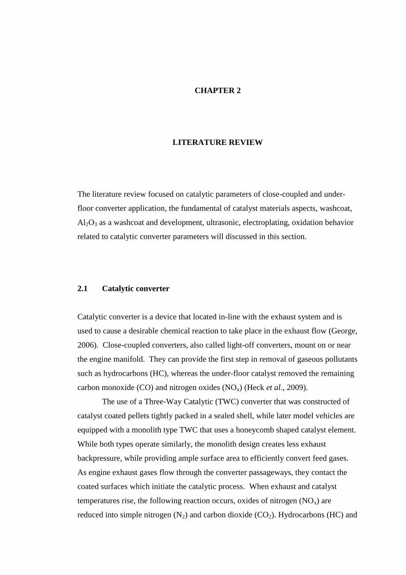
A catalytic converter consists of a several component such as substrate,
washcoat and catalyst material through which hot exhaust gas must pass before being
discharged into the air as shown in Figure 2.1.
Figure 2.1: Structure of catalytic converter (Harkonen, 2005)
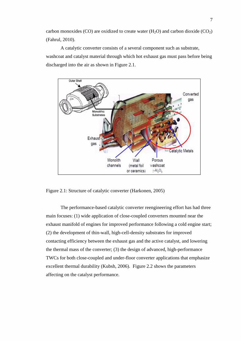
The performance-based catalytic converter reengineering effort has had three
main focuses: (1) wide application of close-coupled converters mounted near the
exhaust manifold of engines for improved performance following a cold engine start;
(2) the development of thin-wall, high-cell-density substrates for improved
contacting efficiency between the exhaust gas and the active catalyst, and lowering
the thermal mass of the converter; (3) the design of advanced, high-performance
TWCs for both close-coupled and under-floor converter applications that emphasize
excellent thermal durability (Kubsh, 2006). Figure 2.2 shows the parameters
affecting on the catalyst performance.
8
Figure 2.2: Parameters affecting on the catalyst performance (Harkonen, 2005)
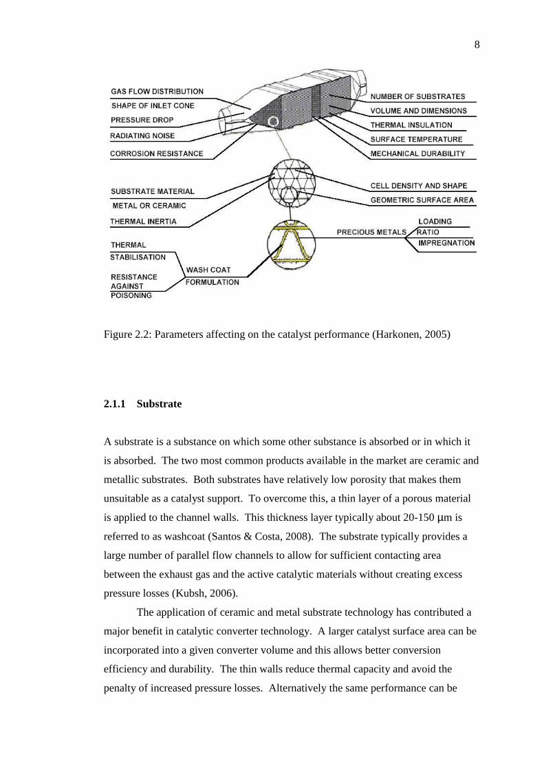
2.1.1 Substrate
A substrate is a substance on which some other substance is absorbed or in which it
is absorbed. The two most common products available in the market are ceramic and
metallic substrates. Both substrates have relatively low porosity that makes them
unsuitable as a catalyst support. To overcome this, a thin layer of a porous material
is applied to the channel walls. This thickness layer typically about 20-150 µm is
referred to as washcoat (Santos & Costa, 2008). The substrate typically provides a
large number of parallel flow channels to allow for sufficient contacting area
between the exhaust gas and the active catalytic materials without creating excess
pressure losses (Kubsh, 2006).
The application of ceramic and metal substrate technology has contributed a
major benefit in catalytic converter technology. A larger catalyst surface area can be
incorporated into a given converter volume and this allows better conversion
efficiency and durability. The thin walls reduce thermal capacity and avoid the
penalty of increased pressure losses. Alternatively the same performance can be
9
incorporated into a smaller converter volume, making the catalyst easier to fit close
to the engine, as cars get more compact (Bode, 1997).
Currently, different cell shapes are commonly used in both metal and ceramic
substrates: sinusoidal, triangular, square and hexagonal (Heck et al., 2001). The
geometrical surface area (GSA) of the catalytic converter substrate is determined by
the cell density, cell shape and converter volume. The rate of conversion in warmed-
up condition is limited by the rate of the mass transfer from the channel to the
catalytic wall. The mass transfer in a smooth channel represents a process of
diffusion and is thus accelerated by a rise in temperature and the difference of
pollutants concentration readially. As the concentration of pollutant substances in
the converter channels decreases because of already converted pollutants the
difference in concentration between the channel core and wall as a driving force
becomes increasingly lower (Bode, 1997).
2.1.1.1 Metallic substrate
Metal-foil-based substrates are made from ferritic-based stainless steel foils brazed
together to form the parallel flow passages. The ferritic foil alloy provides good
oxidation resistance in the exhaust environment, good mechanical strength, and an
oxidized surface that promotes good adhesion of the catalytic coating to the foil
(Kubsh, 2006). Ferritic steels became available that could be made into ultra thin
foils, corrugated and then laid up to form a honeycomb structure. In the beginning
the foils could be made from material only 0.05 mm thick allowing high cell
densities to be achieved. Complex internal structures can be developed and today
wall thickness is down to 0.025 mm and cell densities of 800, 1000 and 1200 cpsi are
available (Bode, 1997).
Metal wire has been attempts to utilize wire meshes made of cheap iron or
stainless steel as support of active catalyst component. However, there have low
surface areas. The wire surface is usually coated with a refractory material of
inorganic powder since catalytically active metals or metal oxides can be well
dispersed by such a modified surface of wire mesh (Yang et al., 2003).
10
Monoliths made of stainless steel or steel alloys are becoming in increasingly
popular as catalyst-supports, mainly because they can be prepared with thinner walls
which offer the potential for higher cell densities with lower pressure drop and with
higher thermal conductibility, resulting in faster heat-up comparing with the ceramic
supports. However, the common designs of steel monoliths, such as corrugated
sheets and plain sheets welded or wrapped together into a monolithic structure, may
reduce inter-phase mass/heat transfer rates and suppress radial mixing (Sun et al.,
2007).
Metallic monoliths became available in the early 1990s. Because of their
high open frontal areas, approaching 90 %, the metallic monoliths provide higher
geometric surface area while offering lower resistance to flow, i.e. back pressure.
Furthermore, metallic monoliths are being used extensively in close coupled
applications due to their higher thermal conductivity that guarantees more uniform
temperature distribution between the monolith channels as compared to that of
ceramic monoliths. The metallic substrate presents better conversions, particularly
for HC and CO at high space velocities as compared to the ceramic substrate, mainly
because of its larger geometric surface area and lower transverse peclet number
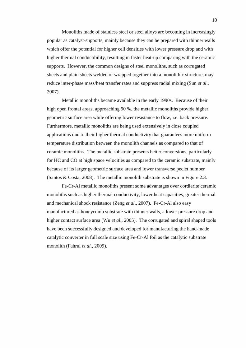
(Santos & Costa, 2008). The metallic monolith substrate is shown in Figure 2.3.
Fe-Cr-Al metallic monoliths present some advantages over cordierite ceramic
monoliths such as higher thermal conductivity, lower heat capacities, greater thermal
and mechanical shock resistance (Zeng et al., 2007). Fe-Cr-Al also easy
manufactured as honeycomb substrate with thinner walls, a lower pressure drop and
higher contact surface area (Wu et al., 2005). The corrugated and spiral shaped tools
have been successfully designed and developed for manufacturing the hand-made
catalytic converter in full scale size using Fe-Cr-Al foil as the catalytic substrate
monolith (Fahrul et al., 2009).
11
Figure 2.3: The design of metallic monolith substrate (VBulletin Solutions Inc, 2011)
2.1.1.2 Fe-Cr-Al metallic substrate
Fe-Cr-Al alloys are often used in high temperature applications like support material
for catalytic converters, heating elements in furnaces, burner elements and hot gas
filters. When exposed to high temperatures an alumina film grows on the surface of
the Fe-Cr-Al material. In order to provide a good protection the alumina should
grow slowly, be adherent, dense and inert, which is true for α-Al2O3. Besides the
only stable form α-Al2O3, alumina has several metastable polymorphs such as γ-, θ-
and δ-Al2O3, which provides less protection in corrosive environments.
In practice the amount of Al in the alloy is limited to about 7 wt.%, by the
fact that higher concentrations of Al make the alloy brittle and impossible to process
by conventional rolling. Thin foil Fe-Cr-Al materials are more sensitive to Al
depletion during oxidation due to a minor total Al reservoir than in bulk Fe-Cr-Al
materials. Fe-Cr-Al materials are usually alloyed with reactive elements (RE) such
as zirconium (Zr), yittrium (Y), cerium (Ce), lanthanium (La) or hafnium (Hf).
Although the exact effects of reactive elements on the oxidation characteristics are
not known, reactive elements may influence the oxide growth mechanism and
improve the oxide scale adhesion (Engkvist et al., 2009).
12
The corrosion resistance of Fe-Cr-Al in oxidizing atmosphere is due to the
formation of a highly protective chromium and aluminum oxide layer on the surface,
which effectively separates the oxidizing atmosphere from the pure alloy. Because
α-Al O is very stable at high temperatures it would be beneficial to maximize its
content at the surface (Airiskallio et al., 2010).
2.2 Washcoat
The honeycomb ceramic support is coated with a material of high surface area called
the washcoat, which acts as a host for the noble metal catalysts. The most widely
used material in the application of washcoat is Al2O3, especially for environmental
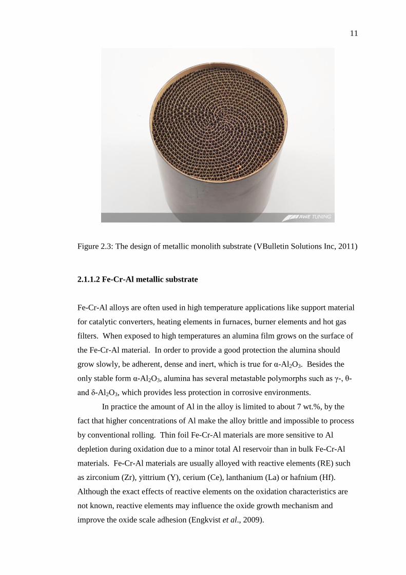
applications (Agrafiotis & Tsetsekou, 2000). At one time it was thought to provide
only a surface to disperse the catalytic substance to maximize the catalytic surface
area as illustrated in Figure 2.4. However, it is now clear that it can play a critical
role in maintaining the activity, selectivity and durability of the finished catalyst.
Generally, the most common carriers are the high surface area inorganic
oxides, most of which is Al2O3. The pollutant containing gases enter the channels
uniformly and diffuse to and through the washcoat pore structure to the catalytic sites
where they are converted catalytically. The amount of geometric surface area, upon
which the washcoat is deposited, is determined by the number and diameter of the
channels. There is a limit as to how much washcoat can be deposited, since too
much result in a decrease of the effective channel diameter, thereby increasing the
pressure drop to an unacceptable level. γ-Al2O3 have large surface area, good pore
size distribution, surface acidic properties, composition of trace components and
crystal structure (Heck et al., 2009).
13
Figure 2.4: Schematic diagram for catalytic sites dispersed on a high surface area of
Al2O3 carrier bonded to a monolith support (Heck et al., 2009)
2.2.1 Al2O3 washcoat
Al2O3 is the most commonly material oxide used as carrier/washcoat in environment
catalysis technology. It will be used to develop a model of a heterogeneous catalyst.
To maximize reaction rates, it is essential to ensure the accessibility of all reactants
to the active catalytic component sites dispersed within the internal pore network of
the washcoat. Many different sources of alumina have various surface
characterization including areas, pore size distributions, surface acidic properties,
composition of trace components and crystal structures. Its chemical and physical
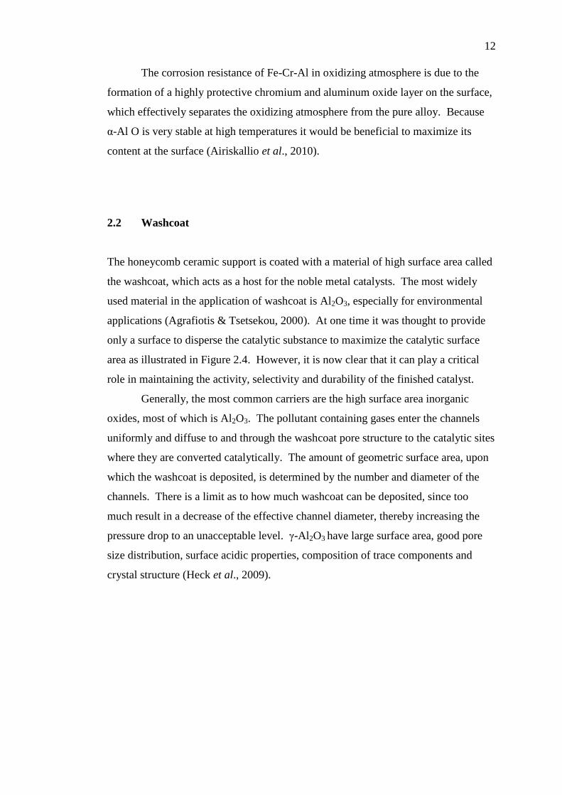
properties depend on sample preparation, purity and thermal history. An image of γ-
Al2O3 and α-Al2O3 for scanning electron micrograph analysis at 80.000
magnifications is shown in Figure 2.5. γ-Al2O3 have a surface area of about 150
m2/g. It is clearly seen that the structure composed of primary Al2O3 particles
agglomerated forming highly porous networks (Heck et al., 2009).
14
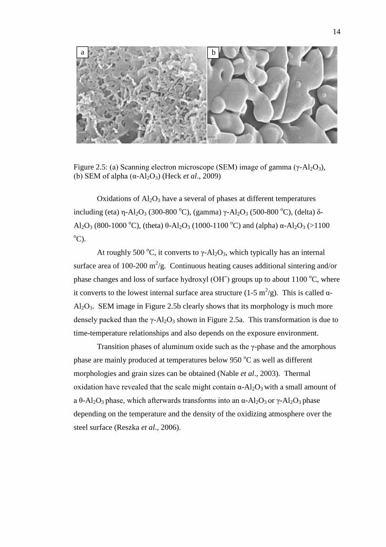
Figure 2.5: (a) Scanning electron microscope (SEM) image of gamma (γ-Al2O3),
(b) SEM of alpha (α-Al2O3) (Heck et al., 2009)
Oxidations of Al2O3 have a several of phases at different temperatures
including (eta) η-Al2O3 (300-800 oC), (gamma) γ-Al2O3 (500-800
oC), (delta) δ-
Al2O3 (800-1000 oC), (theta) θ-Al2O3 (1000-1100
oC) and (alpha) α-Al2O3 (>1100
oC).
At roughly 500 oC, it converts to γ-Al2O3, which typically has an internal
surface area of 100-200 m2/g. Continuous heating causes additional sintering and/or
phase changes and loss of surface hydroxyl (OHˉ) groups up to about 1100 oC, where
it converts to the lowest internal surface area structure (1-5 m2/g). This is called α-
Al2O3. SEM image in Figure 2.5b clearly shows that its morphology is much more
densely packed than the γ-Al2O3 shown in Figure 2.5a. This transformation is due to
time-temperature relationships and also depends on the exposure environment.
Transition phases of aluminum oxide such as the γ-phase and the amorphous
phase are mainly produced at temperatures below 950 oC as well as different
morphologies and grain sizes can be obtained (Nable et al., 2003). Thermal
oxidation have revealed that the scale might contain α-Al2O3 with a small amount of
a θ-Al2O3 phase, which afterwards transforms into an α-Al2O3 or γ-Al2O3 phase
depending on the temperature and the density of the oxidizing atmosphere over the
steel surface (Reszka et al., 2006).
a b
15
2.3 Particle size distribution of the carrier / washcoat
The particles in a colloidal suspension or emulsion are seldom with the same size but
varying in shapes. The size and shape is therefore a significant problem. Emulsion
droplets can usually be assumed to be spherical (long as the distance between the
droplets is large enough). For solid particles general descriptions of shape like
spheroidal, rod- or disk-shaped, even when the system contains individual particles
with other shapes. The particle size may also vary over quite a wide range. It is not
unusual for the particles of a suspension produced in a grinding operation, for
example, to vary by a factor of 100 from the smallest to the largest size. To describe
such situations, it normally breaks the range up into a number of classes and try to
find out how many particles are in each size range. This range is called the particle
size distribution (PSD), and it can be represented in the form of a histogram (Figure
2.6) (Heck et al., 2009).
The size of the agglomerated particles that make up the carrier must be
compatible with the surface roughness and macro-pore structure of the carrier
powders to produce the uniform particle size which will be coated on substrate.
Sieves of various mesh sizes have been standardized, and thus, one can determine
particle size ranges by noting the percentage of material, usually based on weight,
that passes through one mesh size but is retained on the next finer screen based on
standard ASTM D4513-85, (1998). The stack of sieves is vibrated, allowing the
finer particles to pass through coarser screens until retained by those screens finer in
opening than the particle size of the material of interest. Each fraction is then
weighed and a distribution is determined.
This method is reliable only for particles larger than about 40 micron. Below
this size, sieving is slow and charging effects influence measured values.
Sophisticated instrumentation is available for measuring the distribution of finer
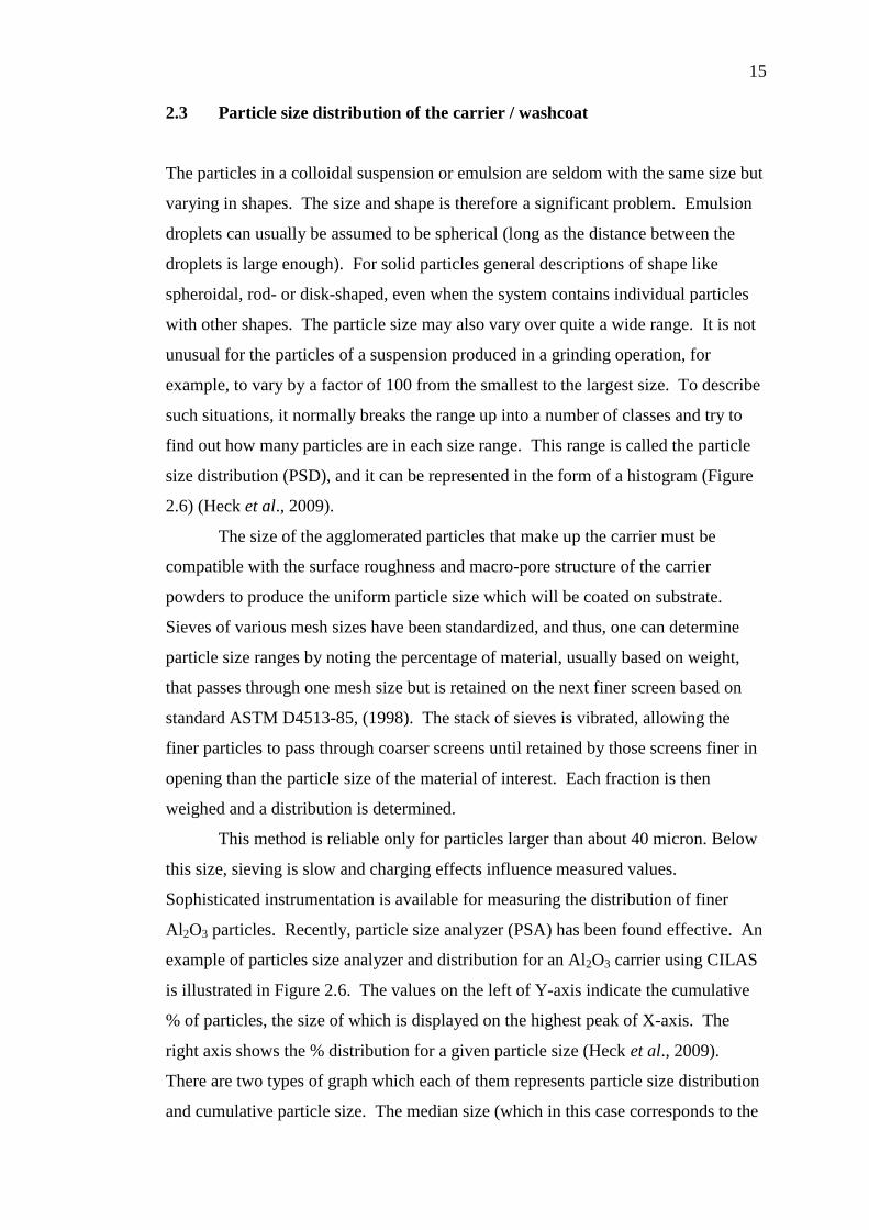
Al2O3 particles. Recently, particle size analyzer (PSA) has been found effective. An
example of particles size analyzer and distribution for an Al2O3 carrier using CILAS
is illustrated in Figure 2.6. The values on the left of Y-axis indicate the cumulative
% of particles, the size of which is displayed on the highest peak of X-axis. The
right axis shows the % distribution for a given particle size (Heck et al., 2009).
There are two types of graph which each of them represents particle size distribution
and cumulative particle size. The median size (which in this case corresponds to the
16
maximum frequency) and the spread of the particles distribution is represented by the
maximum peak.
Figure 2.6: Particle size measurement using CILAS particle size analyzer (PSA)
(Heck et al., 2009)
2.4 Washcoat development on Fe-Cr-Al metallic substrate
In addition to the microstructural requirements for a washcoat material, excellent
adhesion on the substrate is a further crucial requirement and optimization of the
parameters that affect the adhesion of the washcoat layer on the support is
imperative. Reduction of the washcoat powder size (less than 2 microns) down to
colloidal dimensions seems to be necessary for the achievement of satisfactory
adhesion and endurance of the washcoat under the severe operating conditions
(Agrafiotis & Tsetsekou, 2000).
For the washcoat, the higher surface area is very desirable (Jiang et al., 2005).
Besides the surface area, other desirable washcoat properties are thermal stability and
appropriate pore size distribution. A material combining these properties and most
widely used in washcoat application is γ-Al2O3. The washcoat phase usually
17
contains smaller quantities of other phases, which have a particular function. For
example, cerium (Ce) and lanthanium (La) are frequently added to γ-Al2O3 in order
to induce oxygen storage capacity and thermal stability respectively (Agrafiotis &
Tsetsekou, 2000).
The main problem for the washcoat is to maintain a high geometric surface
area, appropriate pore size distribution and firm cohesion to the support at high
temperatures (Wu et al., 2001). The coating adhesion between the metallic support
and the ceramic washcoat becomes a problem. The deposition of the γ-Al2O3
washcoat on the metallic monolith has not been as well developed yet as that on the
ceramic monolith. The non-porous nature of the metal foil, coupled with the
mismatch in the thermal expansion between the foil and the ceramic washcoat,
contributes to a washcoat adhesion problem during thermal cycling (Wu et al., 2005).
The utilization of Al2O3 as catalyst combined with Fe-Cr-Al as a support
needs a comprehensive study due to its chemical and physical changing at catalytic
converter. For example, the coating adhesion between the metallic support and the
ceramic washcoat becomes a problem due to it has different thermal expansion
coefficients. In previous investigation, washcoat development was deposited by sol-
pyrolysis method (Zheng et al., 2007), precipitation and dip-coating method
(Valentini et al. (2001), impregnation method (Betta, 1997), plasma spraying
technique (Wu et al., 2001), situ hydrothermal method (Wei et al., 2005) and
electrophoretic deposition (Sun et al., 2007). These methods must be conducted
through a complicated sequence to obtain the washcoat requirements. Therefore, this
research will discussed the ultrasonic treatment with nickel electroplating combine
with oxidation for developing γ-Al2O3 washcoat on Fe-Cr-Al substrate. This method
is simple and cheaper than previous research.
18
2.5 Catalyst materials for catalytic converter
The use of catalyst material is to stimulate or enhance a chemical reaction that
naturalize or reduce the toxic by-products of combustion. As exhaust and catalyst
temperatures rise, the following reaction occurs, oxides of nitrogen (NOx) are
converted into simple nitrogen (N2) and carbon dioxide (CO2). Hydrocarbons (HC)
and carbon monoxides (CO) are oxidized to create water (H2O) and carbon dioxide
(CO2). In automobiles, this typically results in 90% conversion of carbon monoxide,
hydrocarbons, and nitrogen oxides into less concentration gas which leads to
environmental friendly. Catalysts are either platinum-group metals or base metals
such as chromium, nickel, and copper which are heated by exhaust gas in range of
500 - 700 ºC. At this temperature unburned hydrocarbons and carbon monoxide are
further oxidized, while oxides of nitrogen are chemically reduced in a second
chamber with a different catalyst. Platinum-group metals or noble metals are any of
several metallic chemical elements that have outstanding resistance to oxidation,
even at high temperatures. The noble metals that used as a catalyst material is
usually include rhenium, ruthenium, rhodium, palladium, silver, osmium, iridium,
platinum, and gold. However, these materials are limited supply sources and
expensive (George, 2006).
2.5.1 Nickel as catalyst material
The catalytic properties, metal dispersion and the structural features of species
depend on the method to process these materials and on the support used. The usage
of catalyst will depend on the type of dopant used in order to form a durable, sulfur
tolerant, high catalytic activity catalyst. In many cases, the selected dopants studied
were magnesium (Mg), zirconium (Zr), molybdenum (Mo), manganese (Mn), ferum
(Fe), cobalt (Co) and copper (Cu) (Valentini et al., 2003).
The Ni-based catalysts have high activity, stability and selectivity. Therefore,
the development of such catalysts is an attractive challenge (Valentini et al., 2004).
The investigation of a Ni-based steam reforming catalyst was developed for the
coating of microstructures (Stefanescu et al., 2007).
19
Nickel oxide (NiO) exhibited high activity and selectivity of methane due to
the ability of NiO to undergo reduction process owing to the presence of defect sites
of the surface. Despite of the fast catalyst deactivation and carbon deposition, NiO
catalyst was favorable due to its high thermal stability and low price. Therefore,
nickel oxide can be considered as the best catalyst material for catalytic converter
(Buang et al., 2008).
The catalysts for catalytic converter are mostly related to the precious group
of metals platinum (Pt), palladium (Pd) and rhodium (Rh) (Kirby, 2009). However
these materials are expensive, therefore some materials are used as a substitute such
as nickel. Nickel oxide (NiO) catalyst could be a potential candidate in catalyst
material and cheaper than precious group of metals platinum (Pt), palladium (Pd) and
rhodium (Rh). Nickel oxide application is also effectively for the NOx absorber
catalyst in order to reduce the emissions of hydrogen sulfide (H2S) during desulfation
(Elwart, 2006). The utilization of nickel as catalyst combined with Fe-Cr-Al as a
support needs a comprehensive study due to catalytic converter which works in high
temperature condition (Dou, 2005). NiO produced from a heated pure nickel at 900
oC that the oxide grain size is sufficiently large for lattice diffusion to predominate
over grain boundary transport (Young, 2008).
2.6 Ultrasonic surface treatment
Surface deformation is a widespread and effective method for hardening metallic
materials. With this method, the surface of a material properties can be improved is
a subject of high compressive stresses, which results in a better product strength,
durability, and reliability. Many surface deformation techniques have been
employed including rolling, ball treatment, and shot blasting (peening). Ultrasonic
surface hardening provides an efficient alternative because it can reduce the time.
Applied ultrasonic vibrations relieve residual stresses and improve surface finish and
hardness, thereby providing a better wear resistance of products (Mason & Lorimer,
2002).
20
Recently an ultrasonic surface treatment, similar to shot peening, has been
developed. In this process a powerful ultrasonic field is generated to transfer high
kinetic energy to steel balls that hit the surface of the workpiece being treated. The
energy transferred to the workpiece during a one-ball impingement event is small.
The required surface strain is achieved through repeated action on the surface of the
workpiece. The process creates homogeneous residual stress simultaneously on each
side of the parts to be treated. The process will act on improvement of the surface of
the material.
2.6.1 Reactions involving metal or solid surfaces
There are two types of chemical reaction occurred on the material surface, first in
which the metal is a reagent and is consumed in the process and second in which the
metal functions as a catalyst. While it is certainly true that any cleaning of metallic
surfaces will enhance their chemical reactivity, in many cases it would seem that this
effect alone is not sufficient to explain the extent of the sonochemically enhanced
reactivity. In such cases it is thought that sonication method serves to sweep reactive
products, clear of the metal surface and thus present renewed clean surfaces for
reaction. Other methods include the possibility of enhanced single electron transfer
(SET) reactions at the surface (Mason & Lorimer, 2002).
2.6.2 Reactions involving powders or other particulate matter
Just as with the metal surface reactions described above, the efficiency of
heterogeneous reactions involving solids dispersed in liquids will depend upon the
available reactive surface area and mass transfer. Conventional technology involves
agitating and stirring with rotating devices and baffled pipes as the processors of
fluids when mixing, reacting or dissolving small and submicron sized particles on an
industrial scale. This can take many hours, days or even weeks until the desired
properties are obtained. The main problem with conventional rotational mixing
21
techniques, when trying to disperse solid particles of 10 microns in diameter or
smaller in a liquid is that the rate of mixing and mass transfer of these particles
through the medium reaches a maximum. In fact the mass transfer coefficient K
reaches a constant value of about 0.015 cm s-1
in water, and speed of rotational
agitation, no matter how large this increase may be. Sonication provides a solution
to this problem in that power ultrasound will give greatly enhanced mixing (Mason
& Lorimer, 2002).
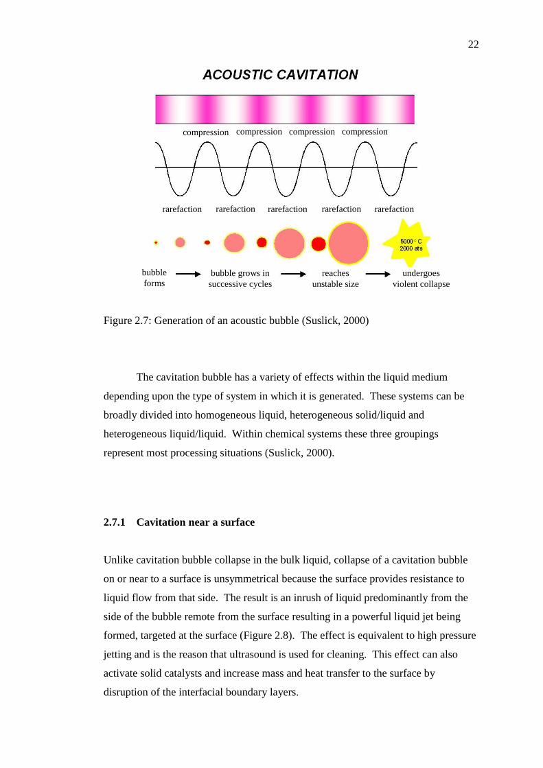
2.7 Acoustic cavitation
Power ultrasound enhances chemical and physical changes in a liquid medium
through the generation and subsequent destruction of cavitation bubbles. Like any
sound wave ultrasound is propagated via a series of compression and rarefaction
waves induced in the molecules of the medium through which it passes (Suslick,
2000). At sufficiently high power the rarefaction cycle may exceed the attractive
forces of the molecules of the liquid and cavitation bubbles will form. Such bubbles
grow by a process known as rectified diffusion i.e. small amounts of vapour (or gas)
from the medium enters the bubble during its expansion phase and is not fully
expelled during compression. The bubbles grow over the period of a few cycles to
an equilibrium size for the particular frequency applied. It is the fate of these
bubbles when they collapse in succeeding compression cycles which generates the
energy for chemical and mechanical effects (Figure 2.7). Cavitation bubble collapse
is a remarkable phenomenon induced throughout the liquid by the power of sound.
In aqueous systems at an ultrasonic frequency of 20 kHz each cavitation bubble
collapse acts as a localised "hotspot" generating temperatures of about 4,000 K and
pressures in excess of 1000 atmospheres.
22
Figure 2.7: Generation of an acoustic bubble (Suslick, 2000)
The cavitation bubble has a variety of effects within the liquid medium
depending upon the type of system in which it is generated. These systems can be
broadly divided into homogeneous liquid, heterogeneous solid/liquid and
heterogeneous liquid/liquid. Within chemical systems these three groupings
represent most processing situations (Suslick, 2000).
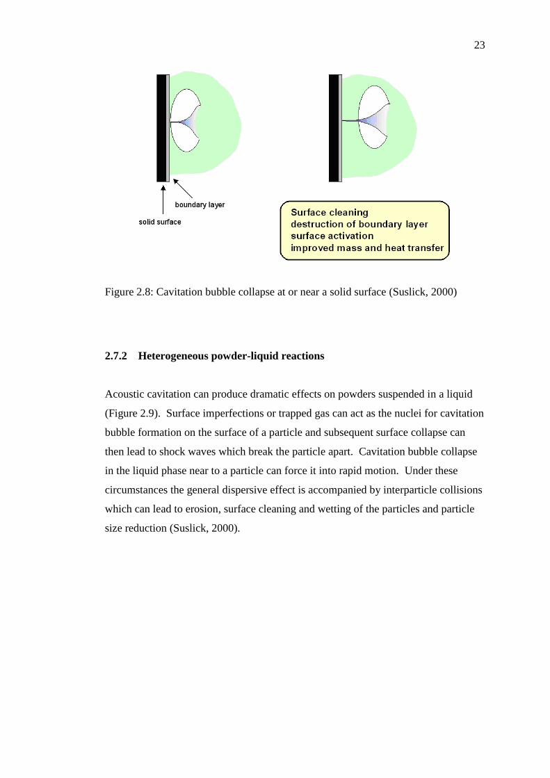
2.7.1 Cavitation near a surface
Unlike cavitation bubble collapse in the bulk liquid, collapse of a cavitation bubble
on or near to a surface is unsymmetrical because the surface provides resistance to
liquid flow from that side. The result is an inrush of liquid predominantly from the
side of the bubble remote from the surface resulting in a powerful liquid jet being
formed, targeted at the surface (Figure 2.8). The effect is equivalent to high pressure
jetting and is the reason that ultrasound is used for cleaning. This effect can also
activate solid catalysts and increase mass and heat transfer to the surface by
disruption of the interfacial boundary layers.
compression compression compression compression
rarefaction rarefaction rarefaction rarefaction rarefaction
bubble
forms bubble grows in
successive cycles
reaches
unstable size
undergoes
violent collapse
23
Figure 2.8: Cavitation bubble collapse at or near a solid surface (Suslick, 2000)
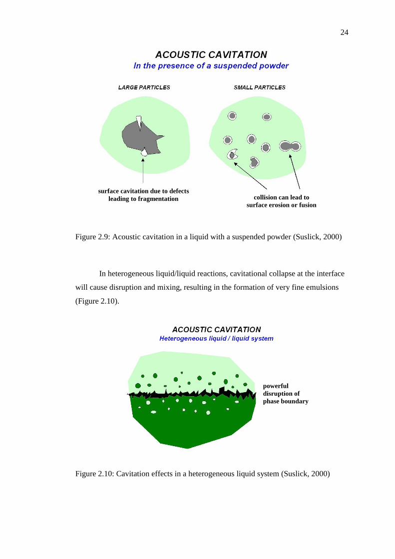
2.7.2 Heterogeneous powder-liquid reactions
Acoustic cavitation can produce dramatic effects on powders suspended in a liquid
(Figure 2.9). Surface imperfections or trapped gas can act as the nuclei for cavitation
bubble formation on the surface of a particle and subsequent surface collapse can
then lead to shock waves which break the particle apart. Cavitation bubble collapse
in the liquid phase near to a particle can force it into rapid motion. Under these
circumstances the general dispersive effect is accompanied by interparticle collisions
which can lead to erosion, surface cleaning and wetting of the particles and particle
size reduction (Suslick, 2000).
24
Figure 2.9: Acoustic cavitation in a liquid with a suspended powder (Suslick, 2000)
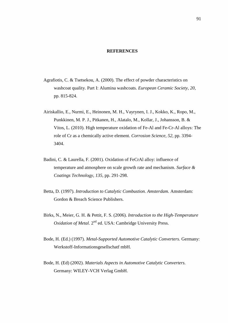
In heterogeneous liquid/liquid reactions, cavitational collapse at the interface
will cause disruption and mixing, resulting in the formation of very fine emulsions
(Figure 2.10).
Figure 2.10: Cavitation effects in a heterogeneous liquid system (Suslick, 2000)
collision can lead to
surface erosion or fusion
surface cavitation due to defects
leading to fragmentation
powerful
disruption of
phase boundary
91
REFERENCES
Agrafiotis, C. & Tsetsekou, A. (2000). The effect of powder characteristics on
washcoat quality. Part I: Alumina washcoats. European Ceramic Society, 20,
pp. 815-824.
Airiskallio, E., Nurmi, E., Heinonen, M. H., Vayrynen, I. J., Kokko, K., Ropo, M.,
Punkkinen, M. P. J., Pitkanen, H., Alatalo, M., Kollar, J., Johansson, B. &
Vitos, L. (2010). High temperature oxidation of Fe-Al and Fe-Cr-Al alloys: The
role of Cr as a chemically active element. Corrosion Science, 52, pp. 3394-
3404.
Badini, C. & Laurella, F. (2001). Oxidation of FeCrAl alloy: influence of
temperature and atmosphere on scale growth rate and mechanism. Surface &
Coatings Technology, 135, pp. 291-298.
Betta, D. (1997). Introduction to Catalytic Combustion. Amsterdam. Amsterdam:
Gordon & Breach Science Publishers.
Birks, N., Meier, G. H. & Pettit, F. S. (2006). Introduction to the High-Temperature
Oxidation of Metal. 2nd
ed. USA: Cambridge University Press.
Bode, H. (Ed.) (1997). Metal-Supported Automotive Catalytic Converters. Germany:
Werkstoff-Informationsgesellschatf mbH.
Bode, H. (Ed) (2002). Materials Aspects in Automotive Catalytic Converters.
Germany: WILEY-VCH Verlag GmbH.
92
Brylewski, T., Dabek, J. & Przybylski, K. (2004). Oxidation kinetics study of the
iron-based steel for solid oxide fuel cell application. Thermal Analysis and
Calorimetry, 77, pp. 207-216.
Buang, N. A., Bakar, W. A. W. A., Marsin, F. M. & Razali, M. H. (2008). CO2 / H2
methanation on nickel oxide based catalyst doped with various elements for the
purification of natural gas. The Malaysian Journal of Analytical Sciences, 12,
pp. 217-223.
Cilas Particle Size Analyzer. (2004). Frequently Asked Questions on Particle Size
Analyse by Laser Diffraction. (France): Cilas Tutorials.
Colloidal Dynamics Pty Ltd. (1999). Particle Size Distributions. Eveleigh
(Australia): Electroacoustics Tutorials.
Connolly, J. R. (2007). Elementary crystallography for X-ray diffraction. Spring, pp.
1-13.
Dou, D. (2005). NiO Catalyst Configurations, Methods for Making NOx Absorbers,
and Methods for Reducing Emissions. U.S. Patent 6,930,073 B2.
Elwart, S. (2006). Sistem and Method for Removing Hydrogen Sulfide from an
Emissions Stream. U.S. Patent 7,104,045 B2.
Engkvist, J., Grehk, T. M., Bexell, U. & Olsson, M. (2009). Early stages of oxidation
of uncoated and PVD SiO2 coated FeCrAl foils. Surface & Coatings
Technology, 203, pp. 2845-2850.
Fahrul, M. (2010). Development and Application of a Computer Aided Engineering
Methodology Supporting the Design Optimization of Automotive Exhaust
Treatment System. Universiti Tun Hussein Onn Malaysia: Master Thesis.
93
Fahrul, M., Sebayang, D. & Untoro, P. (2009). Apparatus for Producing a Spiral
Shape of Corrugated Sheet Metal for Catalyst Substrate of Catalytic Converter.
Proc. Of Int. Conf. on Advances in Mechanical Engineering.
George, D. B. (1994). Nickel Plating. 5th
ed. USA: ASM International.
George, S. (2006). The Catalytic Converter. Retrieved Oct 20, 2010.
Ghosh, J., Mazumdar, S., Das, M., Ghatak, S. & Basu, A.K. (2008). Microstructural
characterization of amorphous and nanocrystalline boron nitride prepared by
high energy ball milling. Materials Research Bulletin, 43, pp. 1023-1031.
Harkonen, M. (2005). Exhaust Gas Catalysts. Nanotechnology in Northern Europe
Helsinki Fair Center. Ecocat Oy.
Haugsrud, R. (2003). On the high temperature oxidation of nickel. Corrosion Sience,
45, pp. 211-235.
Heck, R.M., Farrauto, R.J. & Gulati, S.T. (2009). Catalytic Air Pollution Control
Commercial Technology. 3rd
ed. USA: John Wiley & Sons, Inc.
Jiang, P., Lu, G., Guo, Y., Guo, Y., Zhang, S. & Wang, X. (2005). Preparation and
properties of a γ-Al2O3 washcoat deposited on a ceramic honeycomb. Surface
& Coatings Technology, 190, pp. 314-320.
Kirby, C. W. (2009). Catalytic Converter having Three Precious Catalyst Materials.
European Patent Application 734,757 A1.
Kubsh, J. (Ed.) (2006). Advanced Three-way Catalysts. USA: Society of Automotive
Engineers.
Lee, D., Santella, M. L., Anderson, I. M. & Pharr, G. M. (2005). Long-term
oxidation of an as-cast Ni3Al alloy at 900 oC and 1100 oC. Metallurgical and
Materials Transactions, 36 A, pp. 1855-1869.
94
Mason, T. J. & Lorimer, J. P. (2002). Applied Sonochemistry: Uses of Power
Ultrasound in Chemistry and Processing. Weinheim: Wiley-VCH Verlag
GmbH.
Nable, J., Gulbinska, M., Suib, S. L. & Galasso, F. (2003). Aluminum oxide coating
on nickel substrate by metal organic chemical vapor deposition. Surface &
Coatings Technology, 173, pp. 74-80.
Peng, X. (2009). Nanoscale assembly of high temperature oxidation resistant
nanocomposites. Nanoscale, 2, pp. 262-268.
Providing Challenging Ultrasonic Solutions. (2002). Basic Elements of MMM
Systems & How MMM Systems Operate. MPInterconsulting.
Putrasari, Y. (2011). Preparation of NiO Catalyst on FeCrAl Substrate Using
Various Techniques at Higher Oxidation Process. Universiti Tun Hussein Onn
Malaysia: Master’s Thesis.
Reszka, K., Morgiel, J. & Reszka, J. (2006). Structure and properties of an
alumina/amorphous-alumina/platinum catalytic system deposited on FeCrAl
steel. Journal of Microscopy, 224, pp. 46-48.
Rose, I. & Whittington, C. (2002). Nickel Plating Handbook. Finland: OM Group.
Santos, H. & Costa, M. (2008). Evaluation of the conversion efficiency of ceramic
and metallic three way catalytic converters. Energy Conversion &
Management, 49, pp. 291-300.
Sebayang, D., Putrasari, Y., Hasan, S. & Untoro, P. (2010). NiO development on
FeCrAl substrate for catalytic converter using ultrasonic and nickel
electroplating methods. Advanced Material Research Journal, 129-131, pp.
1262-1266.
95
Stefanescu, A., Veen, A. C. V., Brunel, E. D. & Mirodatos, C. (2007). Investigation
of Ni-based steam reforming catalyst developed for the coating of
microstructures. Chemical Engineering Science, 62, pp. 5092-5096.
Sun, H., Quan, X., Chen, S., Zhao, H. & Zhao, Y. (2007). Preparation of well-
adhered γ-Al2O3 washcoat on metallic wire mesh monoliths by electrophoretic
deposition. Applied Surface Science, 253, pp. 3303-3310.
Suslick, K. S. (2000). The Chemistry of Ultrasound. Chicago: Suslick Research
Group Chemistry University of Illinois.
Valentini, A., Carreno, N. L. V., Leite, E. R., Goncalves, R. F., Soledade, L. E. B.,
Maniette, Y., Lengo, E. & Probst, L. F. D. (2004). Improved activity and
stability of Ce-promoted Ni/γ-Al2O3 catalysts for carbon dioxide reforming of
methane. Latin American Applied Reseach, 34, pp. 165-172.
Valentini, A., Carreno, N. L. V., Probst, L .F. D., Lisboafilho, P. N., Schreiner, W.
H., Leite, E. R., & Longo, E. (2003). Role of vanadium in Ni:Al2O3 catalysts
for carbon dioxide reforming of methane. Appl. Catalysis A:General, 255, pp.
211-220.
Valentini, M., Groppi, G. & Cristiani, C. (2001). The deposition of γ-Al2O3 layers on
ceramic and metallic supports for the preparation of structured catalysts.
Catalysis Today, 69, pp. 307-314.
VBulletin Solutions Inc. (2011). Metal Substrate. Retrieved Nov 7, 2010.
Wei, Q., Chen, Z. X., Nie, Z. R. & Hao, Y. L. (2005). Mesoporous activated alumina
layers deposited on FeCrAl metallic substrates by an in situ hydrothermal
method. Alloys and Compounds, 396, pp. 283-287.
Wu, X., Weng, D., Xu, L. & Li, H. (2001). Structure and performance of γ-alumina
washcoat deposited by plasma spraying. Surface & Coatings Technology, 145,
pp. 226-232.
96
Wu, X., Weng, D., Zhao, S. & Chen, W. (2005). Influence of an aluminized
intermediate layer on the adhesion of a γ-Al2O3 washcoat on FeCrAl. Surface &
Coatings Technology, 190, pp. 434-439.
Yang, K. S., Jiang, Z. & Chung, J. S. (2003). Electrophoretically Al-coated wire
mesh and its application for catalytic oxidation of 1.2-dichlorobenzene. Surface
& Coatings Technology, 168, pp. 103-110.
Young, D. J. (2008). High Temperature Oxidation and Corrosion of Metals. 1st ed.
Amsterdam: Elsevier.
Zeng, S. H., Liu, Y. & Wang, Y. Q. (2007). CuO-CeO2/Al2O3/FeCrAl monolithic
catalysts prepared by sol-pyrolysis method for preferential oxidation of carbon
monoxide. Catalysis Letters, 117, pp. 119-126.
Zhao, S., Zhang, J., Weng, D. & Wu, X. (2003). A method to form well adhered
γ-Al2O3 layers on FeCrAl metallic supports. Surface & Coatings Technology,
167, pp. 97-105.


![Water-soluble nickel-bis(dithiolene) complexes as ... · Such a PPT prefers near-infrared (NIR, λ = 700–1100 nm) ... (dmit) 2]2– with 2-methoxy(2-ethoxy(2-ethoxyethyl)) p-toluenesulfonate](https://static.fdocument.org/doc/165x107/5af4b0787f8b9a4d4d8e02bb/water-soluble-nickel-bisdithiolene-complexes-as-a-ppt-prefers-near-infrared.jpg)