UBSF 180-1000 PILLER POWER SYSTEMS … 180-1000 PILLER POWER SYSTEMS UB-SFIII Tech Data.doc 14.03.05...
17
UBSF 180-1000 PILLER POWER SYSTEMS UB-SFIII Tech Data.doc 14.03.05 1 TECHNICAL DATA Technical data UNIBLOCK UBSF 180 – 625 Output data Type Data UBSF 180 UBSF 250 UBSF 500 UBSF 625 Output power 180 kVA 250 kVA 500 kVA 625 kVA Output voltage 480/277 V 440/254 V 440/254 V 440/254 V Output current 217 A 382 A 656 A 820 A Power factor cos ϕ 0,8 (ind.) Voltage stability ± 1% static with symmetrical load ± 5% dynamic with 50% load change Output settling time approx. 150 ms (half-load step-change, voltage outside ± 2%) Output frequency 60 Hz, ± 1% Distortion factor (at linear and symmetrical load) 1,5%/2,5% (Ph-Ph/Ph-N) Overload capacity (at rated voltage) 1 10% for 1 h 25% for 10 min 50% for 2 min Short-circuit current approx. 14 x rated current Permissible load crest factor 2 limitless for nonlinear load Phase angle 120° ± 1° with symmetrical load Load unbalance 3 100% Input data Type Data UBSF 180 UBSF 250 UBSF 500 UBSF 625 Rated voltage 415 V 400 V 380 V / 400 V / 415 V 415 V Permissible voltage deviation +10% / -15% -20% short time Rated frequency (tolerance) 50 Hz (± 5%) Rated current 275 A 355 A 822 A / 773 A / 751 A 859 A Fuse rating 315 A 400 A 1000 A 1250 A Power factor cos ϕ 0,85 inductive Mains rectifier 12 pulse Distortion factor 11% DC link circuit voltage 472 V 500 V 432 V / 459 V / 472 V 472 V 1 Tripping reaction of the output switch is according to tolerance information in IEC 947-2. 2 Crest factor = peak factor = ratio between peak factor and RMS value of a periodic quantity (voltage, current) 3 Load unbalance capacity = different loading of the individual phases in a three-phase system.
Transcript of UBSF 180-1000 PILLER POWER SYSTEMS … 180-1000 PILLER POWER SYSTEMS UB-SFIII Tech Data.doc 14.03.05...
UBSF 180-1000 PILLER POWER SYSTEMS
UB-SFIII Tech Data.doc 14.03.05 1
TECHNICAL DATA
Technical data UNIBLOCK UBSF 180 – 625
Output data
TypeData
UBSF 180 UBSF 250 UBSF 500 UBSF 625
Output power 180 kVA 250 kVA 500 kVA 625 kVA
Output voltage 480/277 V 440/254 V 440/254 V 440/254 V
Output current 217 A 382 A 656 A 820 A
Power factor cos ϕ 0,8 (ind.)
Voltage stability ± 1% static with symmetrical load± 5% dynamic with 50% load change
Output settling time approx. 150 ms(half-load step-change, voltage outside ± 2%)
Output frequency 60 Hz, ± 1%
Distortion factor(at linear and symmetricalload)
1,5%/2,5% (Ph-Ph/Ph-N)
Overload capacity(at rated voltage)1
10% for 1 h25% for 10 min50% for 2 min
Short-circuit current approx. 14 x rated current
Permissible load crest factor2 limitless for nonlinear load
Phase angle 120° ± 1° with symmetrical load
Load unbalance3 100%
Input data
TypeData
UBSF 180 UBSF 250 UBSF 500 UBSF 625
Rated voltage 415 V 400 V 380 V / 400 V /415 V
415 V
Permissible voltage deviation +10% / -15%-20% short time
Rated frequency (tolerance) 50 Hz (± 5%)
Rated current 275 A 355 A 822 A / 773 A /751 A
859 A
Fuse rating 315 A 400 A 1000 A 1250 A
Power factor cos ϕ 0,85 inductive
Mains rectifier 12 pulse
Distortion factor 11%
DC link circuit voltage 472 V 500 V 432 V / 459 V /472 V
472 V
1 Tripping reaction of the output switch is according to tolerance information in IEC 947-2.2 Crest factor = peak factor = ratio between peak factor and RMS value of a periodic quantity (voltage, current)3 Load unbalance capacity = different loading of the individual phases in a three-phase system.
UB-SFIII Tech Data.doc 14.03.05 2
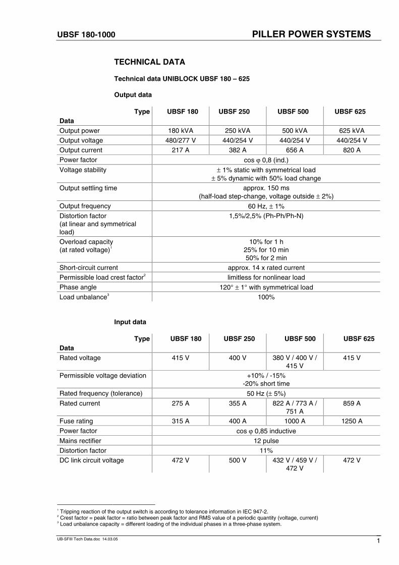
General data
TypeData
UBSF 180 UBSF 250 UBSF 500 UBSF 625
Dimensions1
Width 2438 mm 2438 mm 2740 mm 2740 mm
Depth 865 mm 860 mm 985 mm 985 mm
Height 1900 mm 1900 mm 1900 mm 1900 mm
Weight see table in section “Floor loading capacity”
Wall-mounting? yes
Several sets alongside eachother?
yes
75 dB(A) 75 dB(A) 78 dB(A) 78 dB(A)
as per DIN ISO 3746
Noise level(at a distance of 1 m)
reducing of noise level approx. 5 dB with silencer
Air flow2 6120 m3/h 6120 m3/h 7900 m3/h 7900 m3/h
Max. back pressure3 50 Pa to 75 Pa
MTBF4-value > 90 000 h
MTTR5-value ≤ 24 h
Temperature range 0 °C to 40 °C (≤ 35 °C daily mean average)
Rel. humidity 0 % to 95 % without condensation
Type of protection IP20 as per DIN/VDE 0470 part 1 11/92 IEC529
Efficiency6 88,5 % 88,6 % 89,1 % 90 %
Cooling Regarding room ventilation / air condition please contact us.No air condition is required in case the exhaust air is conducted
out of the room.
1 rounded dimensions2 decreased slight with silencer, resp. air filter3 Built-on accessories (ducts, etc.) must not exceed this value.4 MTBF = Mean Time Between Failures5 MTTR = Mean Time To Repair6 For rated load and cos ϕ = 1. Data vary for other operating modes.
UBSF 180-1000 PILLER POWER SYSTEMS
UB-SFIII Tech Data.doc 14.03.05 3
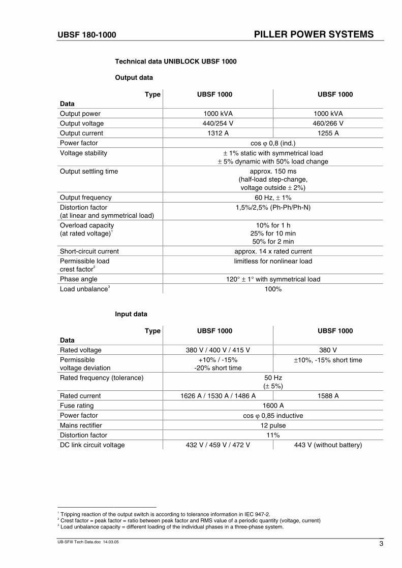
Technical data UNIBLOCK UBSF 1000
Output data
TypeData
UBSF 1000 UBSF 1000
Output power 1000 kVA 1000 kVA
Output voltage 440/254 V 460/266 V
Output current 1312 A 1255 A
Power factor cos ϕ 0,8 (ind.)
Voltage stability ± 1% static with symmetrical load± 5% dynamic with 50% load change
Output settling time approx. 150 ms(half-load step-change,voltage outside ± 2%)
Output frequency 60 Hz, ± 1%
Distortion factor(at linear and symmetrical load)
1,5%/2,5% (Ph-Ph/Ph-N)
Overload capacity(at rated voltage)1
10% for 1 h25% for 10 min50% for 2 min
Short-circuit current approx. 14 x rated current
Permissible loadcrest factor2
limitless for nonlinear load
Phase angle 120° ± 1° with symmetrical load
Load unbalance3 100%
Input data
TypeData
UBSF 1000 UBSF 1000
Rated voltage 380 V / 400 V / 415 V 380 V
Permissiblevoltage deviation
+10% / -15%-20% short time
±10%, -15% short time
Rated frequency (tolerance) 50 Hz(± 5%)
Rated current 1626 A / 1530 A / 1486 A 1588 A
Fuse rating 1600 A
Power factor cos ϕ 0,85 inductive
Mains rectifier 12 pulse
Distortion factor 11%
DC link circuit voltage 432 V / 459 V / 472 V 443 V (without battery)
1 Tripping reaction of the output switch is according to tolerance information in IEC 947-2.2 Crest factor = peak factor = ratio between peak factor and RMS value of a periodic quantity (voltage, current)3 Load unbalance capacity = different loading of the individual phases in a three-phase system.
UBSF 180-1000 PILLER POWER SYSTEMS
UB-SFIII Tech Data.doc 14.03.05 4
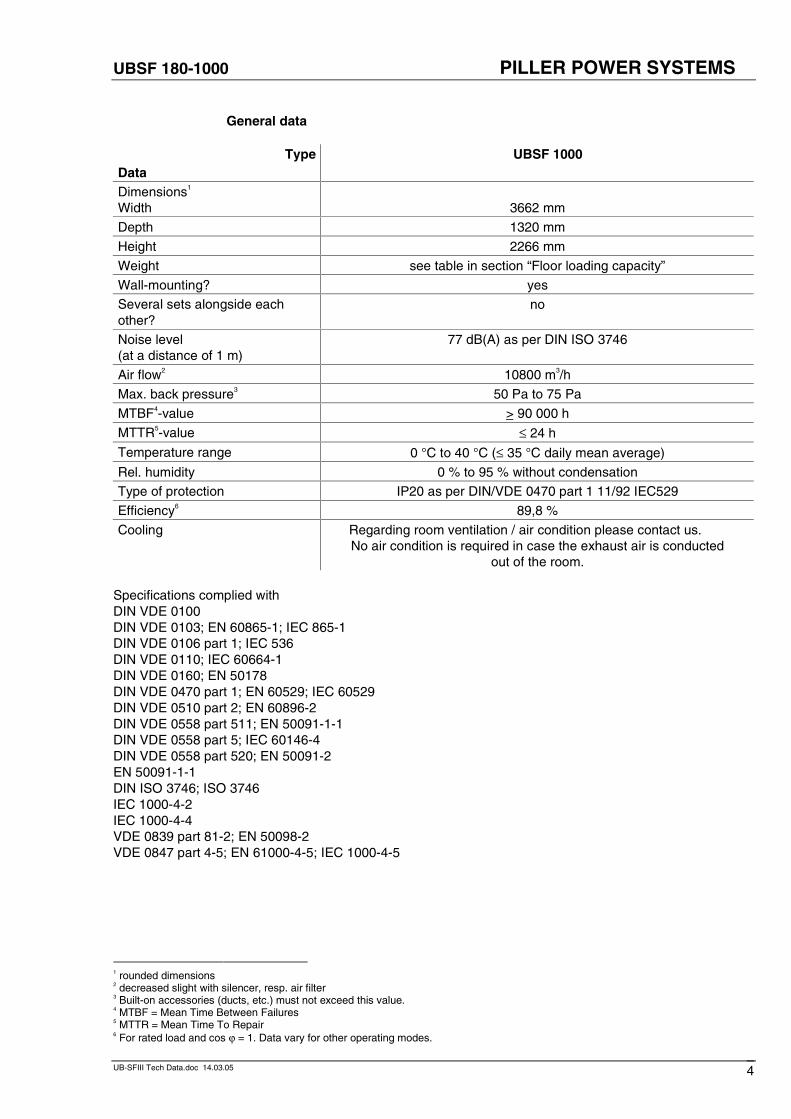
General data
TypeData
UBSF 1000
Dimensions1
Width 3662 mm
Depth 1320 mm
Height 2266 mm
Weight see table in section “Floor loading capacity”
Wall-mounting? yes
Several sets alongside eachother?
no
Noise level(at a distance of 1 m)
77 dB(A) as per DIN ISO 3746
Air flow2 10800 m3/h
Max. back pressure3 50 Pa to 75 Pa
MTBF4-value > 90 000 h
MTTR5-value ≤ 24 h
Temperature range 0 °C to 40 °C (≤ 35 °C daily mean average)
Rel. humidity 0 % to 95 % without condensation
Type of protection IP20 as per DIN/VDE 0470 part 1 11/92 IEC529
Efficiency6 89,8 %
Cooling Regarding room ventilation / air condition please contact us.No air condition is required in case the exhaust air is conducted
out of the room.
Specifications complied withDIN VDE 0100DIN VDE 0103; EN 60865-1; IEC 865-1DIN VDE 0106 part 1; IEC 536DIN VDE 0110; IEC 60664-1DIN VDE 0160; EN 50178DIN VDE 0470 part 1; EN 60529; IEC 60529DIN VDE 0510 part 2; EN 60896-2DIN VDE 0558 part 511; EN 50091-1-1DIN VDE 0558 part 5; IEC 60146-4DIN VDE 0558 part 520; EN 50091-2EN 50091-1-1DIN ISO 3746; ISO 3746IEC 1000-4-2IEC 1000-4-4VDE 0839 part 81-2; EN 50098-2VDE 0847 part 4-5; EN 61000-4-5; IEC 1000-4-5
1 rounded dimensions2 decreased slight with silencer, resp. air filter3 Built-on accessories (ducts, etc.) must not exceed this value.4 MTBF = Mean Time Between Failures5 MTTR = Mean Time To Repair6 For rated load and cos ϕ = 1. Data vary for other operating modes.
UBSF 180-1000 PILLER POWER SYSTEMS
UB-SFIII Tech Data.doc 14.03.05 5
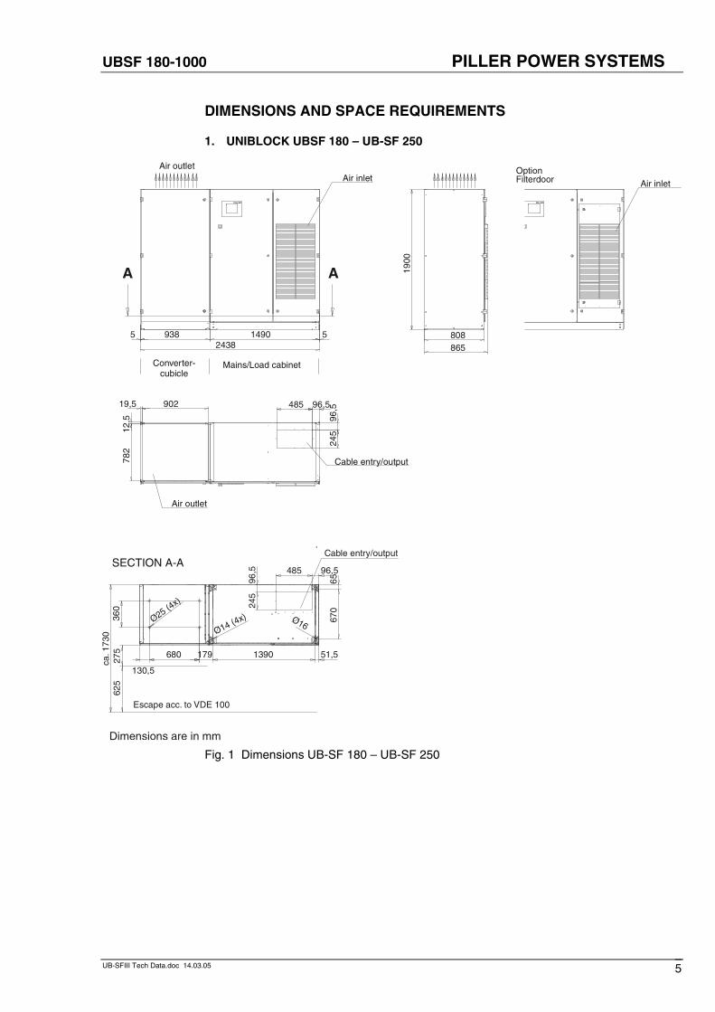
DIMENSIONS AND SPACE REQUIREMENTS
1. UNIBLOCK UBSF 180 – UB-SF 250
Cable entry/output
Air outlet
96,5485
96,5
245
19,5 902
12,5
782
Air inlet
Converter-cubicle
Mains/Load cabinet
Air outlet
5149093852438
A A
808865
1900
Air inlet
OptionFilterdoor
PILLER PILLER
Escape acc. to VDE 100
Cable entry/outputSECTION A-A
96,5
245
96,5485
130,5
680
360
Ø16Ø25 (4x)
6567
0
51,51390179
Ø14 (4x)
275
625
ca. 1
730
Dimensions are in mm
Fig. 1 Dimensions UB-SF 180 – UB-SF 250
UBSF 180-1000 PILLER POWER SYSTEMS
UB-SFIII Tech Data.doc 14.03.05 6
Cable entry/output
Escape acc. to VDE 100
SECTION A-A
Converter-cubicle
Mains/Load cabinet
Air inlet
OptionAir outlet
OptionAir outlet
Air inlet
OptionFilter door
Option BigTouch Panel
Cable entry/output
Air outlet
OptionAir outlet
OptionAir outlet
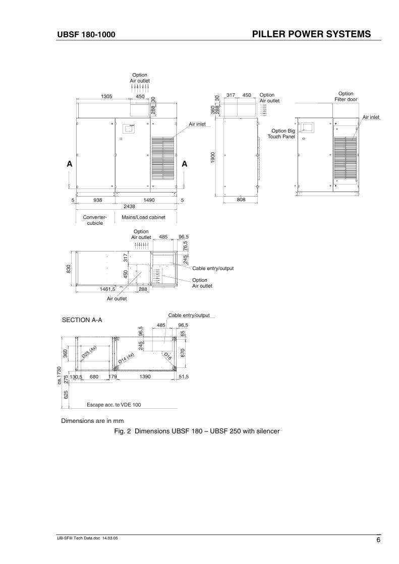
Dimensions are in mm
808
96,5
245
96,5485
130,5 680
360
Ø25 (4x)
Ø16
6567
0
51,51390179
Ø14 (4x)
275
625
ca.1
730
5 938 1490 52438
A A
1305 450
3028
8
1900
3028
8
317 450
360
76,5
245
96,5485
830
1461,5 288
317
450
Fig. 2 Dimensions UBSF 180 – UBSF 250 with silencer
UBSF 180-1000 PILLER POWER SYSTEMS
UB-SFIII Tech Data.doc 14.03.05 7
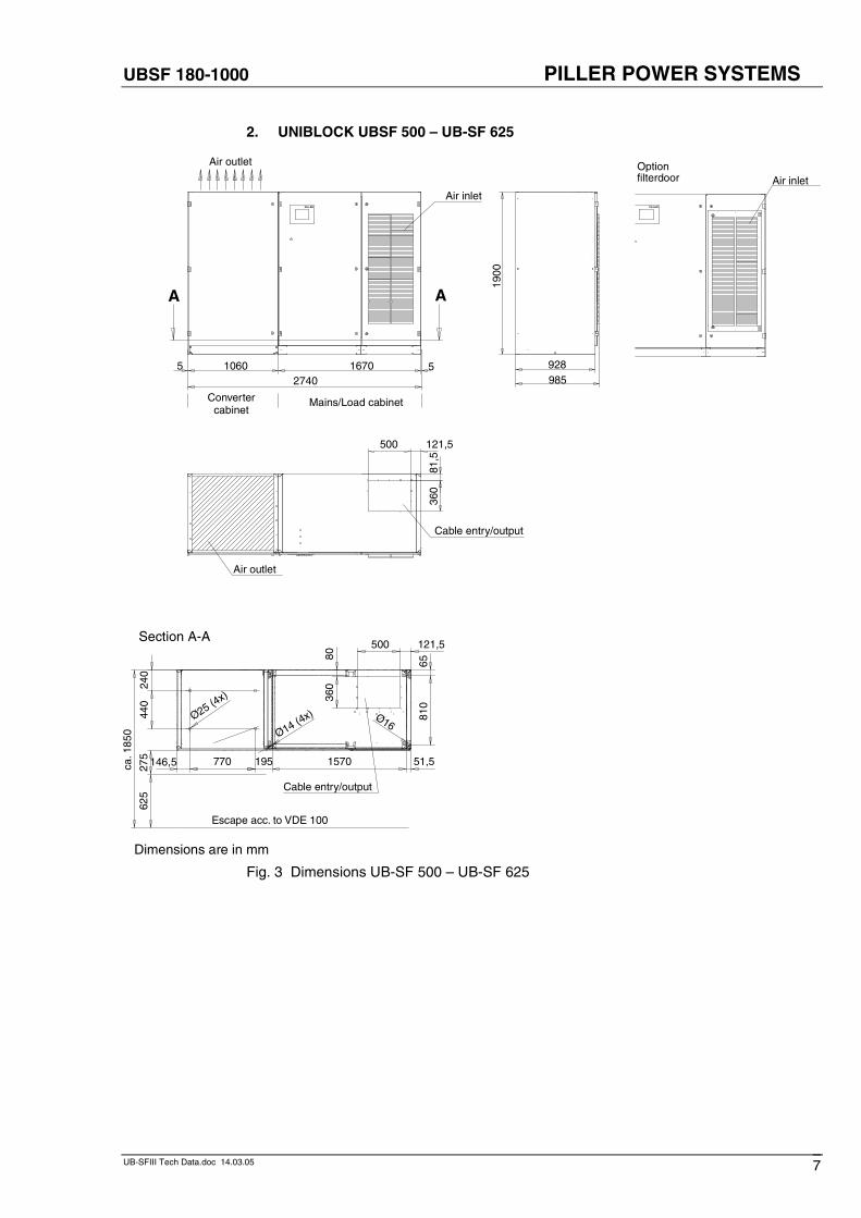
2. UNIBLOCK UBSF 500 – UB-SF 625
1900
928985
Optionfilterdoor Air inlet
Air inlet
Air outlet
Convertercabinet
Mains/Load cabinet
5 1060 1670 52740
A A
Cable entry/output
Air outlet
121,550081
,536
0
PILLER PILLER
Cable entry/output
Escape acc. to VDE 100
Section A-A121,5500
146,5 770
440
240
8036
0
Ø25 (4x)
Ø16
51,51570195
6581
0
Ø14 (4x)
275
625
ca. 1
850
Dimensions are in mm
Fig. 3 Dimensions UB-SF 500 – UB-SF 625
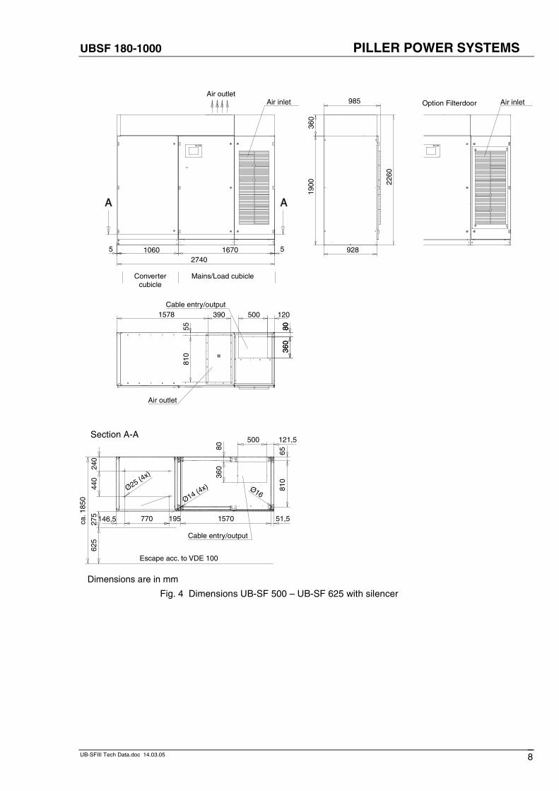
UBSF 180-1000 PILLER POWER SYSTEMS
UB-SFIII Tech Data.doc 14.03.05 8
1900
360
2260
928
985
Convertercubicle
Mains/Load cubicle
Air outletAir inlet
1060 16705 5
2740
Air inletOption Filterdoor
PILLER PILLER
Cable entry/output
Air outlet
120500
8036
0
390
8036
0
5581
0
1578
Cable entry/output
Escape acc. to VDE 100
Section A-A121,5500
146,5 770
440
240
8036
0
Ø25 (4x)
Ø16
51,51570195
6581
0
Ø14 (4x)
275
625
ca. 1
850
Dimensions are in mm
Fig. 4 Dimensions UB-SF 500 – UB-SF 625 with silencer
UBSF 180-1000 PILLER POWER SYSTEMS
UB-SFIII Tech Data.doc 14.03.05 9
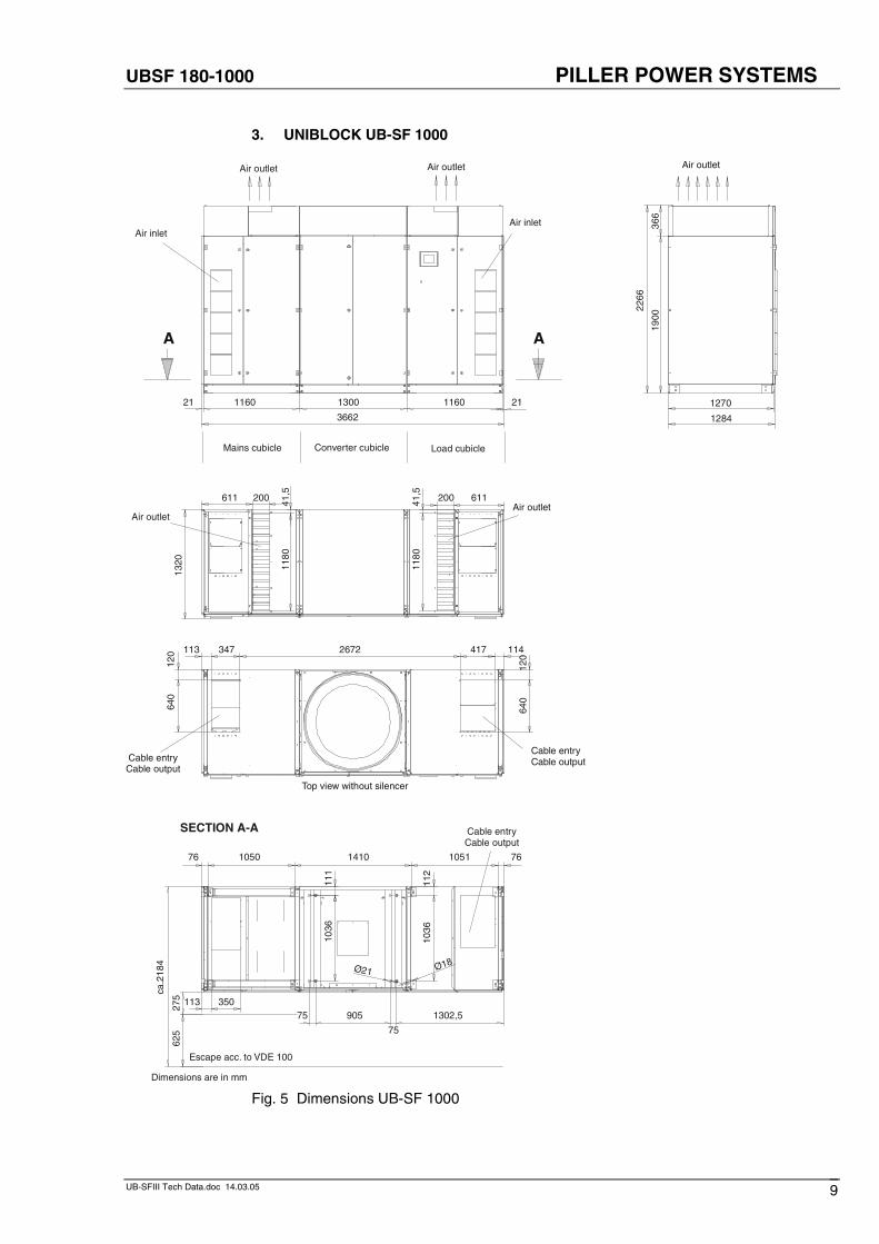
3. UNIBLOCK UB-SF 1000
SECTION A-A Cable entryCable output
Air outlet
Top view without silencer
Cable entryCable output
Cable entryCable output
Air outletAir outlet
Air inletAir inlet
Load cubicleMains cubicle Converter cubicle
Air outlet Air outlet
Escape acc. to VDE 100
Dimensions are in mm
1144172672347113
120
640
120
640
7610511410105076
1302,5
75
90575
111
1036
113 350
112
1036
Ø18Ø21
275
625
ca.2
184
21 1160 1300 1160
3662
21
A
1270
1900
366
1284
2266
A
611 200 200 61141,5
1180
1320
41,5
1180
Fig. 5 Dimensions UB-SF 1000
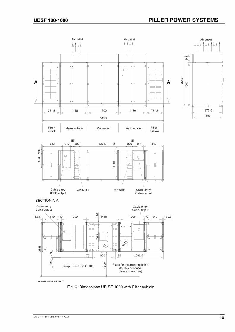
UBSF 180-1000 PILLER POWER SYSTEMS
UB-SFIII Tech Data.doc 14.03.05 10
Air outletAir outlet Air outlet
Filter-cubicle
Mains cubicle Converter Load cubicle Filter-cubicle
Escape acc. to VDE 100 Place for mounting machine(by lack of space, please contact us)
SECTION A-A
Dimensions are in mm
Air outlet Air outlet Cable entryCable output
Cable entryCable output
842 347151
200 (2040) 20081
417 842
130
630
4311
801272,5
1900
366
2266
1286
A A
1160 1300 1160 751,5751,5
5123
Ø 21 Ø 18
160062
527
52186
75 905 75 2032,5
1036
112
56,5 640 110 1050 1410 1050 110 640 56,5
Cable entryCable output
Cable entryCable output
Fig. 6 Dimensions UB-SF 1000 with Filter cubicle
UBSF 180-1000 PILLER POWER SYSTEMS
UB-SFIII Tech Data.doc 14.03.05 11
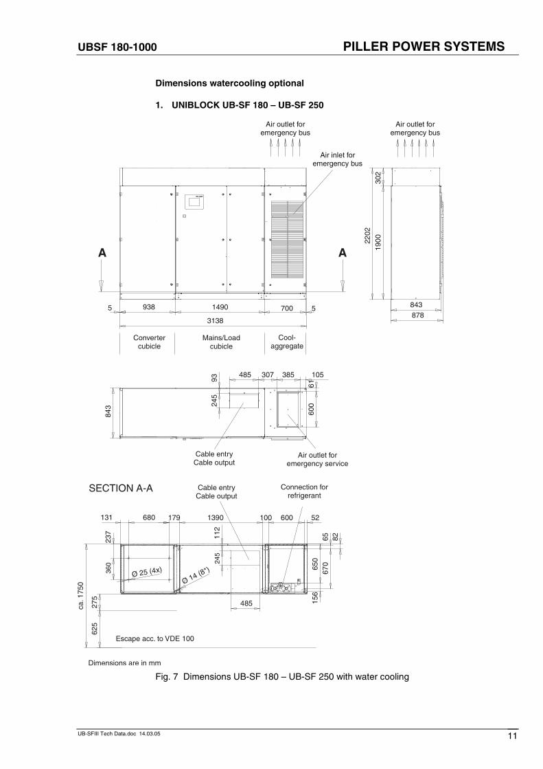
Dimensions watercooling optional
1. UNIBLOCK UB-SF 180 – UB-SF 250
Air outlet foremergency service
Convertercubicle
Cool-aggregate
Mains/Loadcubicle
Air outlet foremergency bus
Cable entryCable output
Air outlet foremergency bus
Air inlet foremergency bus
843 24
593
485 307 385
6160
0
1900
302
2202
878843700 55
3138
A A
938 1490
PILLER
105
SECTION A-A Connection forrefrigerant
Escape acc. to VDE 100
Cable entryCable output
Dimensions are in mm
ca. 1
750
625
275
485
245
112
156
650
131 680
237
360
Ø 25 (4x) 670
65 82
526001001390179
Ø (8*)
14
Fig. 7 Dimensions UB-SF 180 – UB-SF 250 with water cooling
UBSF 180-1000 PILLER POWER SYSTEMS
UB-SFIII Tech Data.doc 14.03.05 12
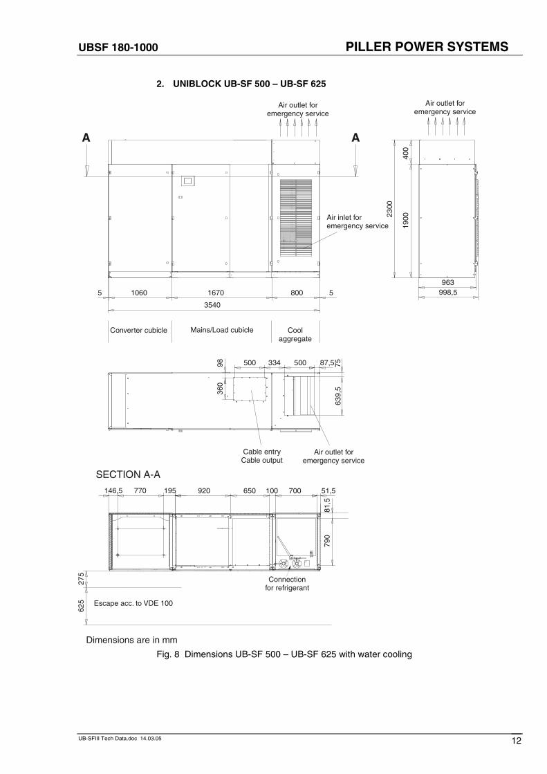
2. UNIBLOCK UB-SF 500 – UB-SF 625
Cable entryCable output
Air outlet foremergency service
Air outlet foremergency service
SECTION A-A
Connectionfor refrigerant
Escape acc. to VDE 100
Air inlet foremergency service
Air outlet foremergency service
Converter cubicle Cool aggregate
Mains/Load cubicle
Dimensions are in mm
87,55003345009836
0
2300
1900
400
963998,5
A A
55
3540
80016701060
639,
575
625
275
81,5
790
920 650 100 700 51,5195770146,5
Fig. 8 Dimensions UB-SF 500 – UB-SF 625 with water cooling
UBSF 180-1000 PILLER POWER SYSTEMS
UB-SFIII Tech Data.doc 14.03.05 13
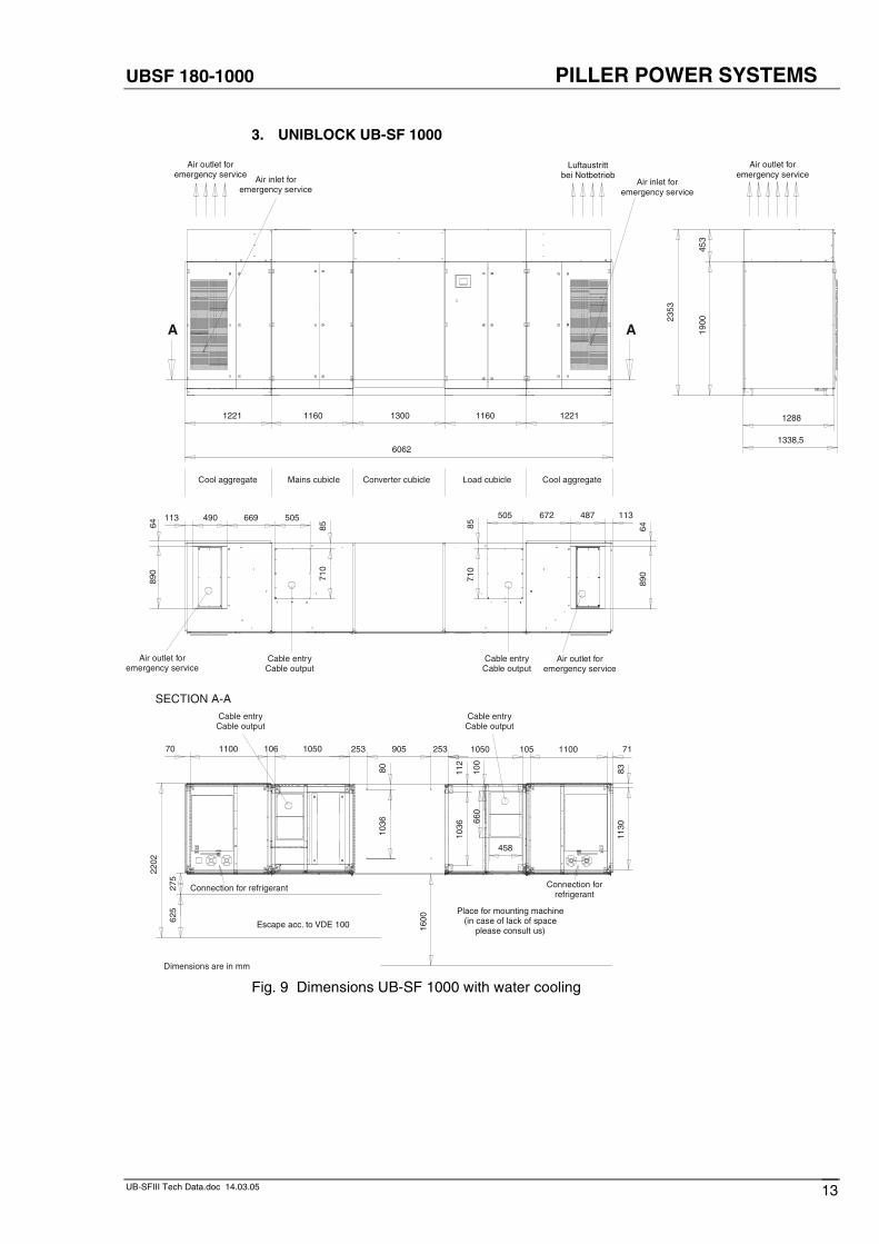
3. UNIBLOCK UB-SF 1000
Air outlet foremergency service
Air outlet foremergency service
Air inlet foremergency service
Air inlet foremergency service
Cool aggregate Mains cubicle Converter cubicle Load cubicle Cool aggregate
Cable entryCable output
Air outlet foremergency service
Cable entryCable output
Air outlet foremergency service
113487672505
6489
0
8571
0
113 490 669 505
8571
0
6489
0
1900
453
2353
Luftaustrittbei Notbetrieb
A A
6062
1221 1160 1300 1160 1221
1338,5
1288
Connection forrefrigerant
SECTION A-A
Escape acc. to VDE 100
Place for mounting machine(in case of lack of space
please consult us)
Connection for refrigerant
Cable entryCable output
Cable entryCable output
Dimensions are in mm
8311
30
7111001051050
112
1036
100
660
458
253905253
8010
36
1050106110070
2202
625
1600
275
Fig. 9 Dimensions UB-SF 1000 with water cooling
UBSF 180-1000 PILLER POWER SYSTEMS
UB-SFIII Tech Data.doc 14.03.05 14
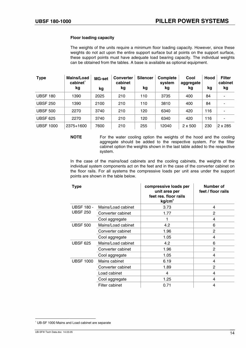
Floor loading capacity
The weights of the units require a minimum floor loading capacity. However, since theseweights do not act upon the entire support surface but at points on the support surface,these support points must have adequate load bearing capacity. The individual weightscan be obtained from the tables. A base is available as optional equipment.
Type Mains/Loadcabinet1
kg
MG-set
kg
Convertercabinet
kg
Silencer
kg
Completesystem
kg
Coolaggregate
kg
Hood
kg
Filtercabinet
kg
UBSF 180 1390 2025 210 110 3735 400 84 -
UBSF 250 1390 2100 210 110 3810 400 84 -
UBSF 500 2270 3740 210 120 6340 420 116 -
UBSF 625 2270 3740 210 120 6340 420 116 -
UBSF 1000 2375+1600 7600 210 255 12040 2 x 500 230 2 x 285
NOTE For the water cooling option the weights of the hood and the coolingaggregate should be added to the respective system. For the filtercabinet option the weights shown in the last table added to the respectivesystem.
In the case of the mains/load cabinets and the cooling cabinets, the weights of theindividual system components act on the feet and in the case of the converter cabinet onthe floor rails. For all systems the compressive loads per unit area under the supportpoints are shown in the table below.
Type compressive loads perunit area per
feet res. floor railskg/cm2
Number offeet / floor rails
Mains/Load cabinet 3.73 4
Converter cabinet 1.77 2
UBSF 180 -UBSF 250
Cool aggregate 1 4
Mains/Load cabinet 4.2 6
Converter cabinet 1.96 2
UBSF 500
Cool aggregate 1.05 4
Mains/Load cabinet 4.2 6
Converter cabinet 1.96 2
UBSF 625
Cool aggregate 1.05 4
Mains cabinet 6.19 4
Converter cabinet 1.89 2
Load cabinet 4 4
Cool aggregate 1.25 4
UBSF 1000
Filter cabinet 0.71 4
1 UB-SF 1000 Mains and Load cabinet are separate
UBSF 180-1000 PILLER POWER SYSTEMS
UB-SFIII Tech Data.doc 14.03.05 15
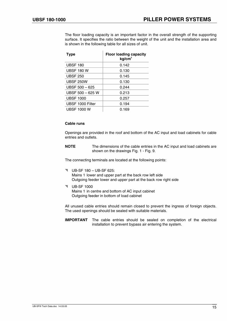
The floor loading capacity is an important factor in the overall strength of the supportingsurface. It specifies the ratio between the weight of the unit and the installation area andis shown in the following table for all sizes of unit.
Type Floor loading capacitykg/cm2
UBSF 180 0.142
UBSF 180 W 0.130
UBSF 250 0.145
UBSF 250W 0.130
UBSF 500 – 625 0.244
UBSF 500 – 625 W 0.213
UBSF 1000 0.257
UBSF 1000 Filter 0.194
UBSF 1000 W 0.169
Cable runs
Openings are provided in the roof and bottom of the AC input and load cabinets for cableentries and outlets.
NOTE The dimensions of the cable entries in the AC input and load cabinets areshown on the drawings Fig. 1 - Fig. 9.
The connecting terminals are located at the following points:
� UB-SF 180 – UB-SF 625:Mains 1 lower and upper part at the back row left sideOutgoing feeder lower and upper part at the back row right side
� UB-SF 1000Mains 1 in centre and bottom of AC input cabinet Outgoing feeder in bottom of load cabinet
All unused cable entries should remain closed to prevent the ingress of foreign objects.The used openings should be sealed with suitable materials.
IMPORTANT The cable entries should be sealed on completion of the electricalinstallation to prevent bypass air entering the system.
UBSF 180-1000 PILLER POWER SYSTEMS
UB-SFIII Tech Data.doc 14.03.05 16
Attaching the connecting cables
The cables should be connected to the brackets of the respective terminal bars with bolts,nuts and two plain washers.
IMPORTANT Please note that in aluminium-copper connections the two metals form anelectrochemical element under the influence of an electrolyte (e.g.moisture), which results in the aluminium being dissolved. If analuminium-copper bond if formed when the UNIBLOCK is connected up,suitable corrosion protection measures must be taken at the connectingpoint.
Bolt sizes:
� M12 x 35 property class 8.8
Bolt tightening torque:
� UB-SF 180 – UB-SF 1000: 60 Nm
All cables should be fitted with DIN 46 234 cable lugs.
IMPORTANT Please ensure that the phase of AC connections are correct sinceincorrect connections can cause damage to the system. (Direction ofrotation of MG-set: counter clockwise, viewed from above).
NOTE If there is sufficient space alongside the set, it is recommended that theside panels of the cabinets be removed when making connections. Thiswill make work easier.
Cable ratings
Cable sizes may be varied by local regulations.
IMPORTANT Cables have to be specified by local contractor.
For reasons of symmetry, if possible, and where permitted, cable type NYCWY 3-core(sleeve with full cross-section) and a separate protective conductor should be used at theoutput.
IMPORTANT The cable must have an upper temperature limit of min. 75° C.
UBSF 180-1000 PILLER POWER SYSTEMS
UB-SFIII Tech Data.doc 14.03.05 17
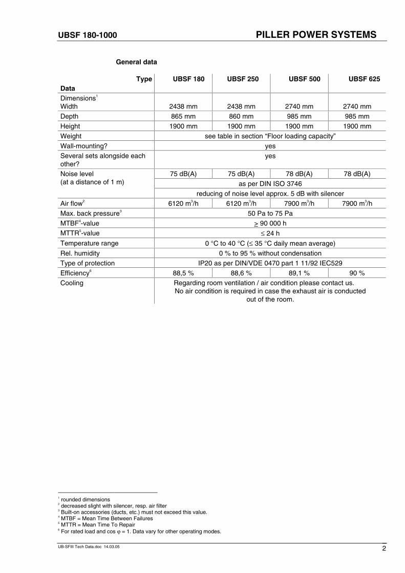
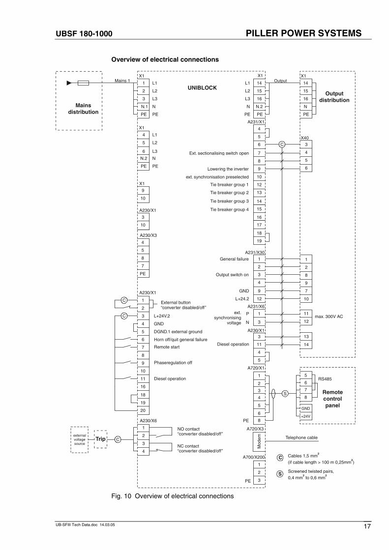
Overview of electrical connections
UNIBLOCK1 L1
X1
2 L2
3 L3
N.1 N
PE PE
Mainsdistribution
Mains 1
1 NO contact“converter disabled/off”
NC contact“converter disabled/off”
2
4
Tripexternalvoltagesource
4 L1
X1
5 L2
6 L3
N.2 N
PE PE
A230/X6
3
3 L+24V.2
1
2
A230/X1
5 DGND.1 external ground
4 GND
6
8
7
10
9
11
A230/X3
3
10
A230/X1
C
C
C
9
10
X1
8
4
5
7
PE
14L1
X1
15L2
16L3
N.2N
PEPE
X1Output
Output distribution
4
5
6
7
8
9
12
13
14
15
1
2
3
4
9
PE
A700/X200
1
2
3
Mod
em
A720/X3
Telephone cable
A720/X1
Remote controlpanel
1
2
3
4
5
6
8
S
14
15
16
N
PE
A231/X1
A231/X30
A231/X6
1
3
P
N
3
4
5
6
1
2
8
9
7
11
12
11
4
5
A230/X1
14
C
12 10
GND
L+24.2
Diesel operation
max. 300V AC
16
17
18
19
3 13
X40
Ext. sectionalising switch open
Lowering the inverter
Tie breaker group 1
Tie breaker group 4
Tie breaker group 3
Tie breaker group 2
General failure
Output switch on
ext.synchronising
voltage
External button“converter disabled/off”
Horn off/quit general failure
Remote start
Phaseregulation off
Diesel operation
S
C
Cables 1,5
(if cable length > 100 m )
mm
0,25mm
2
2
Screened twisted pairs,
0,4 to 0,6 mm mm2 2
16
10ext. synchronisation preselected
18
19
20
PE
RS4855
6
GND
+24V
7
8
Fig. 10 Overview of electrical connections
UBSF 180-1000 PILLER POWER SYSTEMS