TRNSYSlite 5 - η-Τάξη ΕΚΠΑ · “VDI 2078", or user-defined. You should do the selection...
50
TRNSYSlite 5.0 User Interface for an easy, quick and reliable simulation of a single zone building Manual 10/07 M. Hiller TRANSSOLAR Energietechnik GmbH Curiestraße 2 70563 Stuttgart, Germany fax 0711/ 67976-11 email: [email protected] http://www.transsolar.com
Transcript of TRNSYSlite 5 - η-Τάξη ΕΚΠΑ · “VDI 2078", or user-defined. You should do the selection...
TRNSYSlite 5.0User Interface for an easy, quick and reliable simulationof a single zone building
Manual 10/07M. Hiller
TRANSSOLAR Energietechnik GmbH Curiestraße 2 70563 Stuttgart, Germanyfax 0711/ 67976-11 email: [email protected] http://www.transsolar.com
TRNSYSlite manual
page 2
TABLE OF CONTENTS1. Introduction .........................................................................................................................4
2. Features...............................................................................................................................4
3. Installation............................................................................................................................5
4. Working with TRNSYSlite ..................................................................................................6
4.1. Basic Information.............................................................................................................6
4.2. Work steps ......................................................................................................................7
4.2.1. Creating or opening a project ....................................................................................... 7
4.2.2. Input of the general project data................................................................................... 8
4.2.3. Creating variants......................................................................................................... 8
4.2.4. Copying variants......................................................................................................... 9
4.2.5. Deleting variants......................................................................................................... 9
4.2.6. Main window of a variant.............................................................................................. 9
4.2.7. Selection of the room type and/or user-defined construction ......................................... 10
4.2.8. Input of a construction component.............................................................................. 11
4.2.9. Copy an construction element ................................................................................... 14
4.2.10. Modification of construction elements......................................................................... 14
4.2.11. Delete a construction element ................................................................................... 14
4.2.12. Fixed shading .......................................................................................................... 14
4.2.13. Movable shading....................................................................................................... 15
4.2.14. Ventilation ............................................................................................................... 15
4.2.15. Heating.................................................................................................................... 17
4.2.16. Internal loads ........................................................................................................... 18
4.2.17. Convective cooling (air cooling within the room) ........................................................... 20
4.2.18. Thermoactive component (socalled TAB) .................................................................... 21
4.2.19. Comfort evaluation acc. to EN ISO 7730 ..................................................................... 23
4.2.20. Check/print of input via input documentation................................................................ 25
4.2.21. Starting of the simulation........................................................................................... 25
4.2.22. Simulation results..................................................................................................... 30
4.2.23. Graphical representation and statistical analysis of the results with TRNGRPAH............ 33
4.2.24. Further Simulation with TRNSYS ............................................................................... 36
4.3. Settings..........................................................................................................................37
4.3.1. Directories ............................................................................................................... 37
4.3.2. General Settings ...................................................................................................... 37
5. Technical Information.......................................................................................................40
5.1. Zones of cooling loads according VDI 2078..................................................................40
TRNSYSlite manual
page 3
5.2. Construction library .......................................................................................................44
5.2.1. Construction types ................................................................................................... 44
5.2.2. Building materials..................................................................................................... 44
5.2.3. Storage of heat......................................................................................................... 45
5.2.4. U-values .................................................................................................................. 46
Appendix A: license regulation.............................................................................................48
TRNSYSlite manual
page 4
1. Introduction
TRNSYS 16, the internationally known software program, highly complex and dynamicbuildings and systems can be simulated. However, due to the modular structure andthe high flexibility of TRNSYS 16, simple building simulations with only one zone (as inthe case of competitions or early conceptual design) remain relatively complex.
In order to simplify these simulations, TRNSYSlite for TRNSYS was developed.TRNSYSlite is a very useful tool for both experts and beginners. The main characteris-tics of TRNSYSlite are:
• Reduction of the required input by standard values entered into a single interface
• Intuitive user guidance
• Transition of projects easily into TRNSYS 16 for further analysis
TRNSYSlite is also an effective tool for teaching. With TRNSYSlite, engineering and ar-chitecture students can study the thermal behaviour of building designs at an earlystage. At the same time, they can experience integral planning processes firsthand.
2. Features
The current version of TRNSYSlite is a 32-bit application interface for TRNSYS 16. Thefollowing features are included:
• Definition of a thermal zone with- any number of walls/windows- construction catalogue with common pre-defined components- library of common glazing systems- a thermally-active building element (TAB), such as concrete core heating/cooling or slab heating/cooling- outdoor or indoor shading devices- integral shading (overhang, wing wall)- thermal loads- air heating- various strategies for air cooling
• Intelligent control strategies- Movable shading and artificial lighting control depending on solar radiation- Demand-based control of the air heating period and the heating / cooling period of the thermo-active element- Natural stack ventilation
• Supply Air conditioning- Heat recovery with optional humidity recovery
TRNSYSlite manual
page 5
– Auxiliary heating / cooling to a set temperature– Humidification and dehumidification to a set humidity level
• Comfort evaluation according to ISO 7730
• Clear input documentation
• Rotation of the whole building
• Meteorological data library of cooling load zones defined by VDI 2078 for the calcu-lation of a two-week extreme period
• Annual simulation with external meteorological data (TMY2, user defined) for thenorthern and southern hemispheres
• Management of concept variations
• Automatic graphic output of temperature and heat flow diagrams
• Temperature, loads and comfort statistics
• Student version (for universities only)
• English and German versions
Note: TRNSYSlite is a user interface for a licensed TRNSYS 16 package. The simula-tion engine TRNSYS 16 is not included with TRNSYSlite.
3. Installation
Because TRNSYSlite is a 32-bit-aplication, installations can only be done under Win-dows XP, 2000, NT and 98. For installation, insert the CD and start the fileTRNSYSlite_e_SETUP.EXE.
File structure
It is recommended to store the project files in a separate directory e.g.:
Program data in \TRNSYS16_1\TRNSYSlite\
Project data in \TRNSYS16_1\TRNSYSlite\Projects\
The results are stored automatically in the directory of the input (*.kom) file.
Program start
The installation creates a shortcut for TRNSYSlite in the Start Menu, in the TRNSYS16group. To test the program, you can start the enclosed example, found under\TRNSYS16_1\TRNSYSlite\projekte\sample.kom.
TRNSYSlite manual
page 6
4. Working with TRNSYSlite
4.1. Basic Information
General definition :·
• blue fields are editable (except those with greyed text, a previous setting has dis-abled these)
• grey fields are for reference only
All fields can be selected in two ways :·
• with the left mouse button
• with the tab key
Numbers are to be entered with a dot (.) as decimal separator.
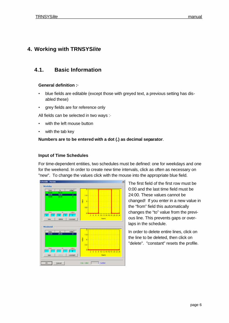
Input of Time Schedules
For time-dependent entities, two schedules must be defined: one for weekdays and onefor the weekend. In order to create new time intervals, click as often as necessary on"new". To change the values click with the mouse into the appropriate blue field.
The first field of the first row must be0:00 and the last time field must be24:00. These values cannot bechanged! If you enter in a new value inthe “from” field this automaticallychanges the “to” value from the previ-ous line. This prevents gaps or over-laps in the schedule.
In order to delete entire lines, click onthe line to be deleted, then click on"delete". "constant" resets the profile.
TRNSYSlite manual
page 7
4.2. Working with a projectThe following procedures describe how to work with a project. Specifically:
• Creating or opening a project
• Input of the general project data
• Creating/copying variants
• Selection of the room type and/or the insolation standard
• Input of the construction data
• Input of the building operation data
• Check input documentation
• Start of the calculation
• Graphical display of the results
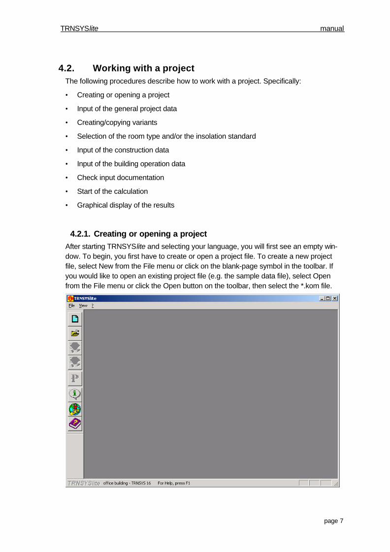
4.2.1. Creating or opening a projectAfter starting TRNSYSlite and selecting your language, you will first see an empty win-dow. To begin, you first have to create or open a project file. To create a new projectfile, select New from the File menu or click on the blank-page symbol in the toolbar. Ifyou would like to open an existing project file (e.g. the sample data file), select Openfrom the File menu or click the Open button on the toolbar, then select the *.kom file.
TRNSYSlite manual
page 8
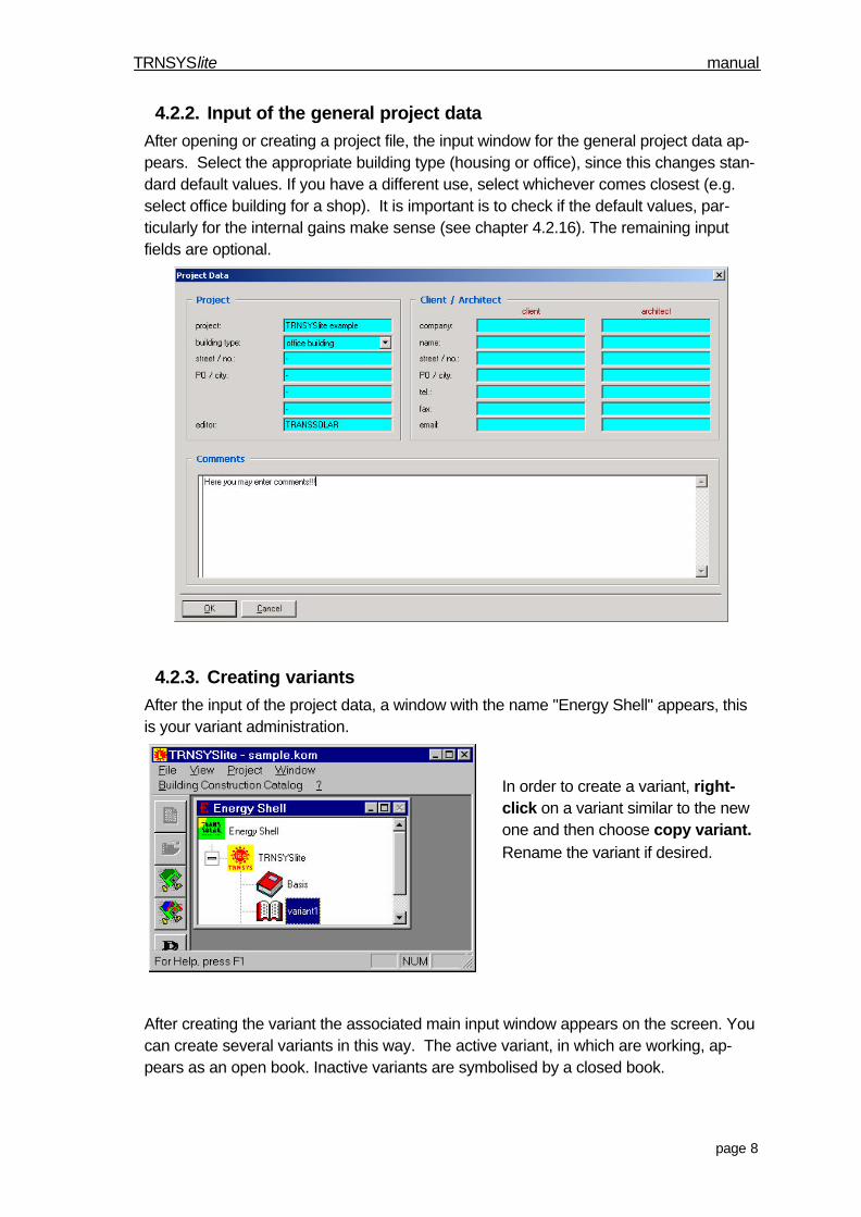
4.2.2. Input of the general project dataAfter opening or creating a project file, the input window for the general project data ap-pears. Select the appropriate building type (housing or office), since this changes stan-dard default values. If you have a different use, select whichever comes closest (e.g.select office building for a shop). It is important is to check if the default values, par-ticularly for the internal gains make sense (see chapter 4.2.16). The remaining inputfields are optional.
4.2.3. Creating variantsAfter the input of the project data, a window with the name "Energy Shell" appears, thisis your variant administration.
In order to create a variant, right-click on a variant similar to the newone and then choose copy variant.Rename the variant if desired.
After creating the variant the associated main input window appears on the screen. Youcan create several variants in this way. The active variant, in which are working, ap-pears as an open book. Inactive variants are symbolised by a closed book.
TRNSYSlite manual
page 9
4.2.4. Copying variantsTo copy a variant you proceed similar to creating one: Right-click on the variant to becopied and then click "copy variant."
4.2.5. Deleting variantsTo delete a variant you proceed similar to creating one. Right-click on the variant todelete and then click "delete variant." The Delete key will also delete the selected vari-ant.
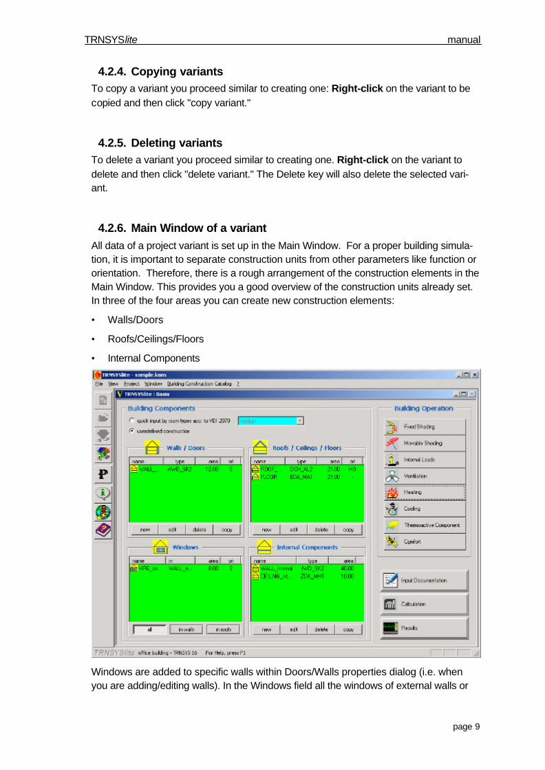
4.2.6. Main Window of a variantAll data of a project variant is set up in the Main Window. For a proper building simula-tion, it is important to separate construction units from other parameters like function ororientation. Therefore, there is a rough arrangement of the construction elements in theMain Window. This provides you a good overview of the construction units already set.In three of the four areas you can create new construction elements:
• Walls/Doors
• Roofs/Ceilings/Floors
• Internal Components
Windows are added to specific walls within Doors/Walls properties dialog (i.e. whenyou are adding/editing walls). In the Windows field all the windows of external walls or
TRNSYSlite manual
page 10
the roof(s) (skylights) are displayed. You can select whether you would like to displayall windows or whether only windows in the walls or in the roof(s) should be displayed.
4.2.7. Selection of the room type and/or user-defined constructionFirst you can select the room type. You have to choose between the German standard“VDI 2078", or user-defined. You should do the selection as the first step, before yousize the individual construction elements (switching to VDI 2078 will cause all user-defined setting to be lost). With this decision you determine which integrated buildingconstruction catalogue is used.
According to VDI 2078, four different room types are available: very light, light, medium,and heavy. These names describe of the thermal storage capability of the walls. Thesetypes are described in the tables below (source: VDI 2078):
Room type: Very Light
Wall layers from outside to inside thickness (m)
Carpet 0.0045
Felt interlayer 0.005
Concrete 0.10
Air gap -
Insulation 0.020
Plaster board 0.020
Room type: Light
Wall layers from outside to inside thickness (m)
Screed topping 0.03
Insulation 0.02
Concrete 0.12
Air gap -
Insulation 0.02
Metal ceiling 0.001
Room type: Medium
Wall layers from outside to inside thickness (m)
Concrete 0.12
Air gap -
Insulation 0.02
Metal ceiling 0.001
Room type: Heavy
Wall layers from outside to inside thickness (m)
PVC- topping 0.002
Screed topping 0.045
Insulation 0.012
Concrete 0.15
TRNSYSlite manual
page 11
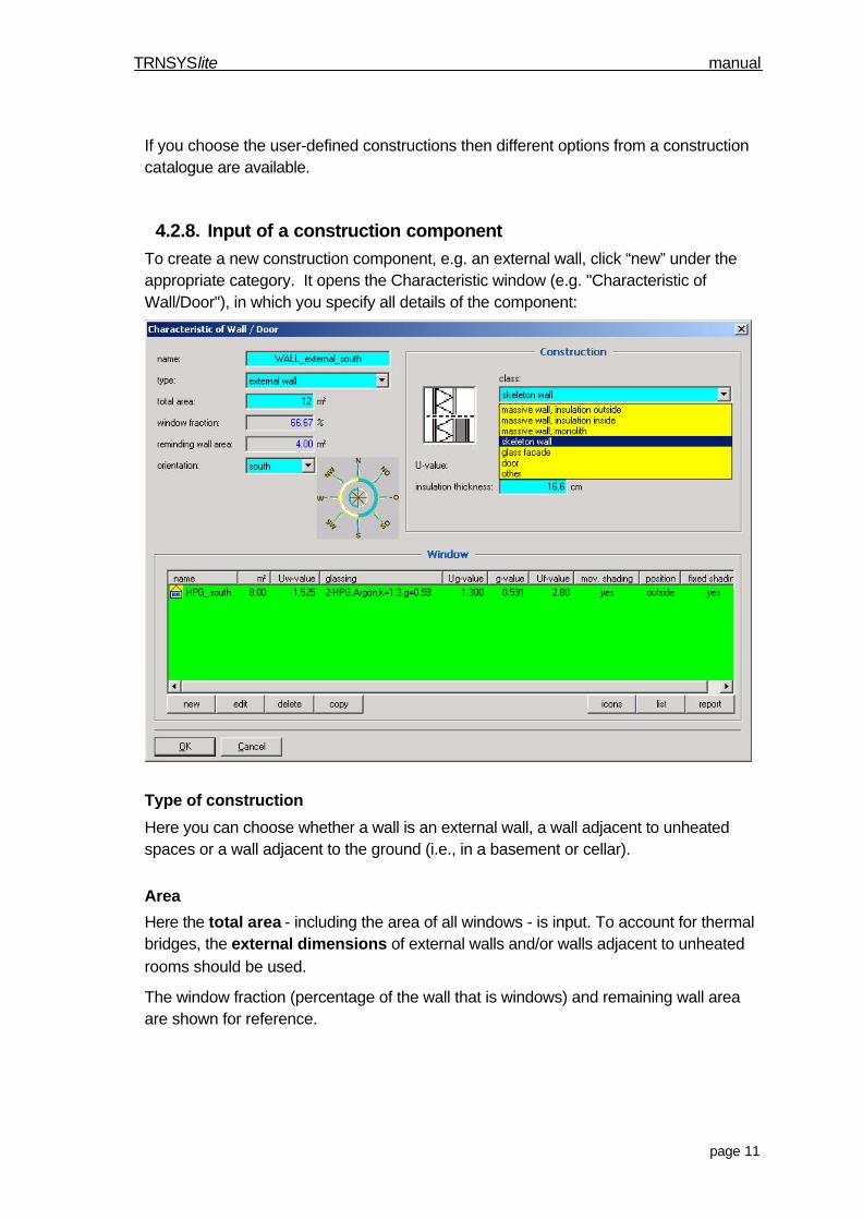
If you choose the user-defined constructions then different options from a constructioncatalogue are available.
4.2.8. Input of a construction componentTo create a new construction component, e.g. an external wall, click “new” under theappropriate category. It opens the Characteristic window (e.g. "Characteristic ofWall/Door"), in which you specify all details of the component:
Type of construction
Here you can choose whether a wall is an external wall, a wall adjacent to unheatedspaces or a wall adjacent to the ground (i.e., in a basement or cellar).
Area
Here the total area - including the area of all windows - is input. To account for thermalbridges, the external dimensions of external walls and/or walls adjacent to unheatedrooms should be used.
The window fraction (percentage of the wall that is windows) and remaining wall areaare shown for reference.
TRNSYSlite manual
page 12
Construction
For user-defined construction, an internal building construction catalogue is used. Itcontains current structural designs which differ in heat gains, heat losses and accu-mulation of energy.
In the first field (“class:”), choose the class of construction desired (e.g. skeleton wall,massive wall). For some classes, further information can be specified in the next field(“type”).
Also in the Construction box, the U-value of the wall is shown (for reference). It ischanged by modifying the insulation thickness in the field below (a generic value for in-sulation is used to calculate this U-value).
Attention!: In the case of a subsequent change of the type of construction element, e.g.flat roof to inclined roof, the insulation thickness is reset to the standard value.
More information to the construction design is available from the building constructioncatalogue (chapter 5.2 )
Orientation (only for external wall, sloped roof)
Here you have to choose one of the 8 orientations (N,S,O,W and NO, NW, SO, SW,note that Ost means East in German). These directions can be fine-tuned later.
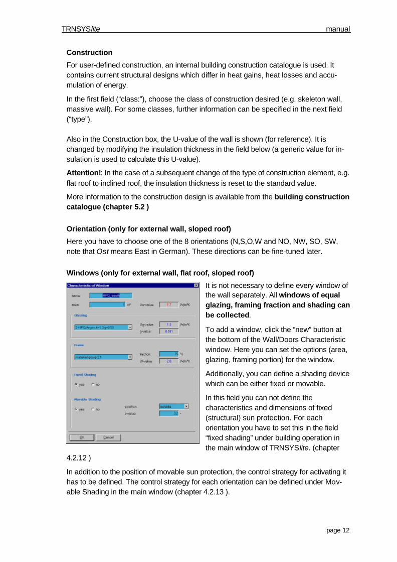
Windows (only for external wall, flat roof, sloped roof)
It is not necessary to define every window ofthe wall separately. All windows of equalglazing, framing fraction and shading canbe collected.
To add a window, click the “new” button atthe bottom of the Wall/Doors Characteristicwindow. Here you can set the options (area,glazing, framing portion) for the window.
Additionally, you can define a shading devicewhich can be either fixed or movable.
In this field you can not define thecharacteristics and dimensions of fixed(structural) sun protection. For eachorientation you have to set this in the field“fixed shading” under building operation inthe main window of TRNSYSlite. (chapter
4.2.12 )
In addition to the position of movable sun protection, the control strategy for activating ithas to be defined. The control strategy for each orientation can be defined under Mov-able Shading in the main window (chapter 4.2.13 ).
TRNSYSlite manual
page 13
In case you define an external sun protection, you can define the fc-value (equal toTRNSYS 16: I – ESHADE) by yourself. For internal sun protection you have to define theopaque fraction and the degree of reflection of the shading device.
Attention: Both fixed and movable sun protection can be set to Active or Inactive withinany simulation. This is set with the control strategy of the movable sun protection, under“Fixed/Movable Shading” of “Building Operation” in the Main Window.
Note regarding temperature of adjacent rooms (only for wall adjacent to un-heated room, ceiling and floor adjacent to unheated room, and space-limiting in-ternal constructions):
TRNSYSlite uses a “one-zone model”. For adjacent rooms, a constanttemperature is assumed, set in the “adj. room temp.” field. Use care whensetting this temperature, as it will affect the simulation of the room underanalysis (e.g. setting the temperature of an empty room under the roof to45°C means that the adjacent room will be affected by this heat). Commonsettings are available, including one to set the temperature identical to thetemperature of the room under analysis.
Note regarding temperature of the ground (only for wall against earth, flooragainst earth):
As with adjacent rooms, the temperature of the ground also affects thesimulation. This is also a constant, either predefined (20°C), user-defined,or sliding (0°C).
Orientation of sloped roof areas
In TRNSYSlite you can define four roof directions with different slopes and orientations.
When setting the first sloped roof, select “sloped ORI 1” in the scroll box, then press“definition.” Now you can see a window for defining slope and orientation of the roof forthe first orientation.
The other surfaces are inactive for this roof (they are greyed-out). Only one orientationper roof can be defined!
You can define as many roofs as desired (e.g. with different construction characteris-tics) but each one has to be set to one of the four possible orientations. Note: with aslope greater than 90° you can produce outward bent areas.
Attention: Subsequent changes to the definition of an orientation applies to all con-struction elements with this orientation! Please check the entered data in the inputdocumentation.
TRNSYSlite manual
page 14
4.2.9. Copy an construction elementTo generate a new construction element, you can copy an existing similar element.Simply select the source element by clicking on it, and press “copy.” This element canthen be modified as desired.
4.2.10. Modification of construction elementsConstruction elements can be modified by selecting it from the list and clicking “edit,” orsimply by double-clicking it. This will open the editing window for the element where youcan change any option.
4.2.11. Delete a construction elementTo delete a construction element, simply select it and press the “delete” button.
Attention: There will be no confirmation dialog for deleting an element!
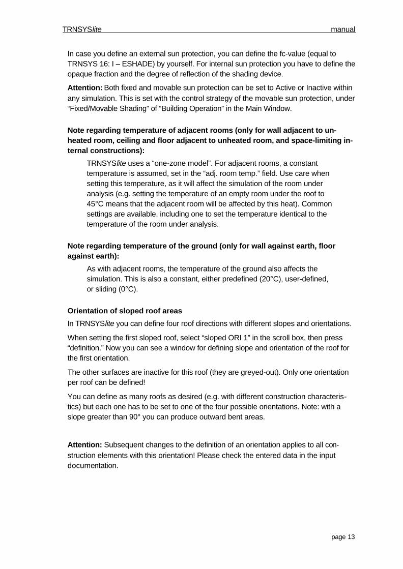
4.2.12. Fixed shadingTo define the fixed shading characteristics, click on “Fixed Shading” in the Building Op-eration section of the Main Window. Here you can define fixed shading devices for the 8orientations available. TRNSYSlite differentiates between fixed shading on the sides(wingwalls) and above (overhangs) the window.
To modify the fixed shading it must first be active. Now it is possible to edit the dimen-sions of the shading. First you have to define the dimensions of the window. Then youactivate the wingwalls and/or overhang options, and fill in the corresponding fields withthe dimensions, as shown in the diagrams.
TRNSYSlite manual
page 15
Attention! For all windows of the same orientation only one definition of fixed shad-ing is possible. However, you can activate/deactivate the shading for each individualwindow.
TRNSYSlite only simulates fixed shading if it is activated in the field of the correspond-ing construction element and in the Fixed Shading settings window!!
By setting a wingwall you can account for shading by neighbouring buildings. It is alsopossible to define a venetian blind by setting the distance between the blinds to theheight of the window. Internally, the shading by one blind is calculated and assigned tothe complete window.
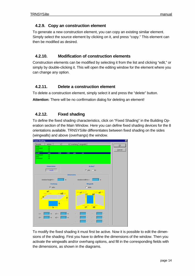
4.2.13. Movable shadingFor movable shading elements of windows the user can define different control strate-gies for the eight facade orientations and the horizontal.
For example: A building has windows with a movable shading device on a flat roof. Se-lect horizontal, and activate if necessary. Now you can set the control strategy. A rea-sonable standard setting appearing as the default, or you can set new conditions. Thereare two conditions for the control strategy - solar radiation and room temperature.
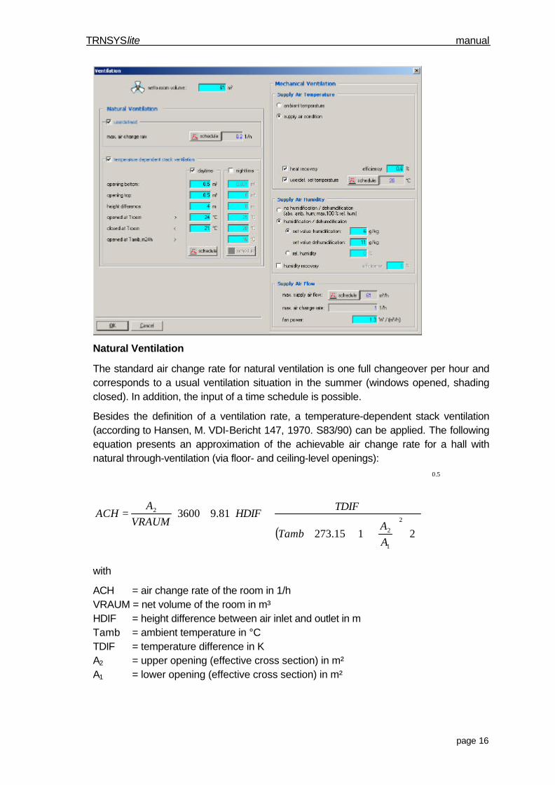
4.2.14. VentilationThere are options for natural and mechanical ventilation with TRNSYSlite. The net vol-ume of the room/thermal zone is required for any analysis.
TRNSYSlite manual
page 16
Natural Ventilation
The standard air change rate for natural ventilation is one full changeover per hour andcorresponds to a usual ventilation situation in the summer (windows opened, shadingclosed). In addition, the input of a time schedule is possible.
Besides the definition of a ventilation rate, a temperature-dependent stack ventilation(according to Hansen, M. VDI-Bericht 147, 1970. S83/90) can be applied. The followingequation presents an approximation of the achievable air change rate for a hall withnatural through-ventilation (via floor- and ceiling-level openings):
( )
5.0
2
1
2
2
2115.273
81.93600
⋅
+⋅+
⋅⋅⋅⋅=
AA
Tamb
TDIFHDIF
VRAUMA
ACH
with
ACH = air change rate of the room in 1/hVRAUM = net volume of the room in m³HDIF = height difference between air inlet and outlet in mTamb = ambient temperature in °CTDIF = temperature difference in KA2 = upper opening (effective cross section) in m²A1 = lower opening (effective cross section) in m²
TRNSYSlite manual
page 17
Caution: The effective cross section has to be entered, not the geometrical cross sec-tion. For many cases, the following equation gives an acceptable approximation:
effective cross section = 0.6 * geometrical cross section
Such a natural ventilation system can be applied during daytime and/or night time. Fornight ventilation the 24h mean value of the ambient temperature can be used for a sea-sonal ventilation strategy (Summer / Winter).
Mechanical Ventilation
For mechanical ventilation an air handling unit with heat/cold recovery and optional hu-midity recovery can be defined. Afterwards the supply air can be heated or cooled to auser-defined set temperature.
The outlet temperature of the heat/cold recovery TWRG is given by:
TWRG = ηsens,ef f · ( TABL – TAUL ) + TAUL
with:
TWRG = outlet temperature of the heat/cold recovery
TAUL = outdoor air temperature
TABL = extract air temperature (= room temperature)
ηsens,eff = efficiency of the heat/cold recovery
The control strategy of the heat/cold recovery allows for the following:
• Frost protection (the minimum allowed exhaust air temperature is set to 4 °C )
• Bypass switching, if the outlet temperature of the heat/cold recovery is above theset temperature of supply air (The flow rate of the bypass is variable.)
• Bypass switching, if dehumidification is required and the outlet temperature of theheat/cold recovery is above ambient temperature.
For the supply air humidity several control strategies can be defined:
• no humidification and dehumidification (outdoor humidity)
• humidification and dehumidification to a set value
• humidity recovery of extracted air
Humidity recovery can be defined only in conjunction with heat/cold recovery.
Note: The power consumption for mechanical ventilation does not increase the tem-perature of the supply air.
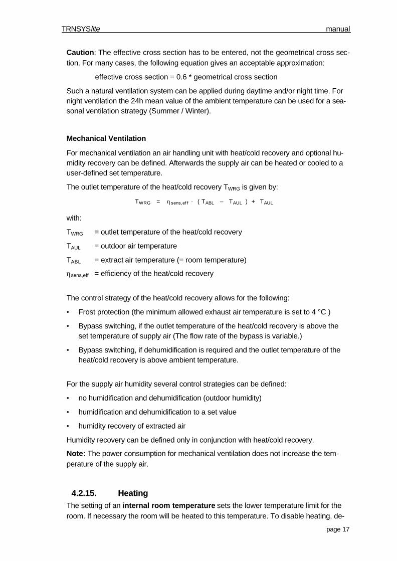
4.2.15. HeatingThe setting of an internal room temperature sets the lower temperature limit for theroom. If necessary the room will be heated to this temperature. To disable heating, de-
TRNSYSlite manual
page 18
fine an internal room temperature which would never actually be reached in the roomduring the simulation (e.g. 0°C). To do this you have to define the according input valuesin the time schedule.
There are two ways to define the annual heating period. Besides defining fixed datesfor the start and end point, a demand-controlled strategy using the 24h mean outdoortemperature is available. This way, the heating may be turned on, for example, on colddays in early summer (more accurately modelling real conditions).
In addition, a set point for the minimum required relative humidity can be defined.Caution: The set point for humidification has to be lower than the set point for dehu-midification (chapter 4.2.17 )
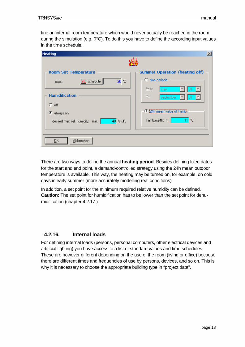
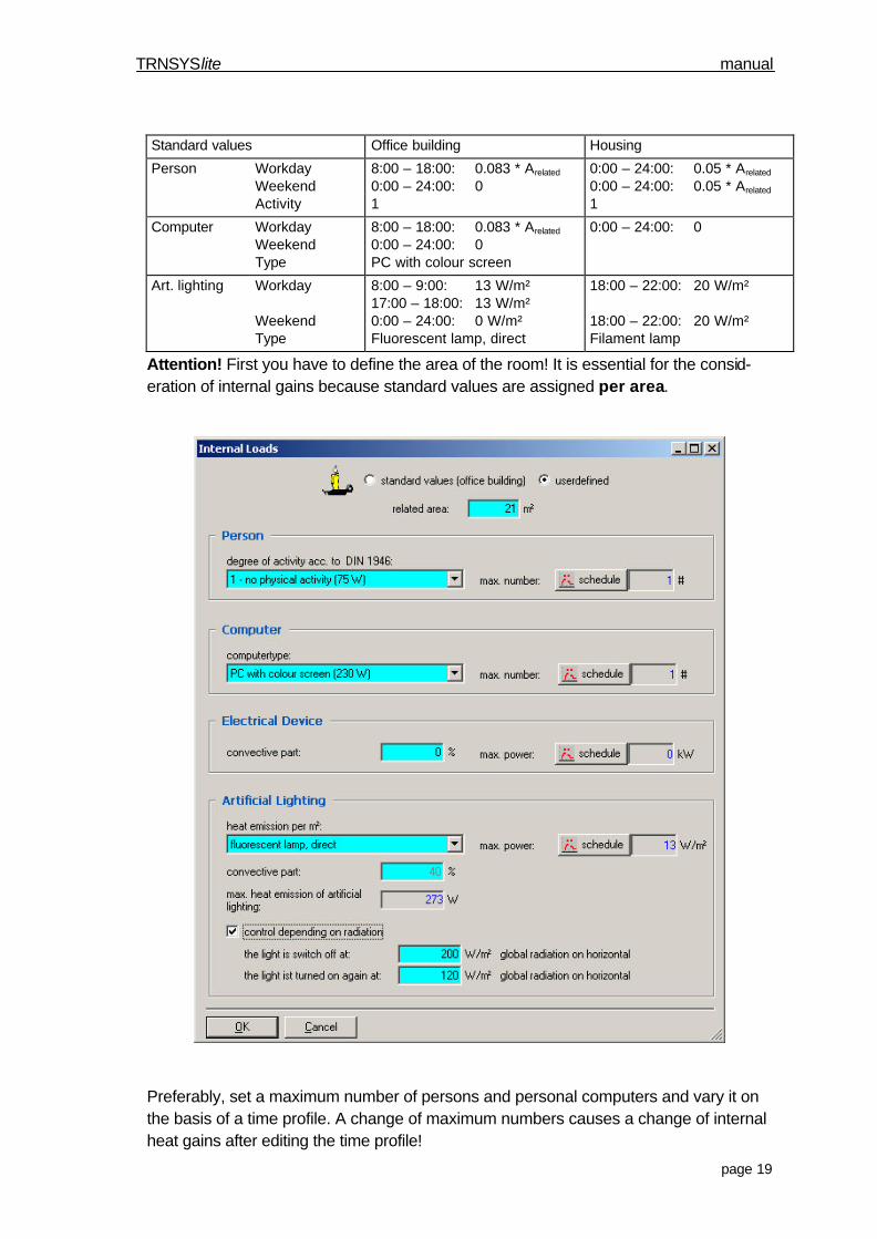
4.2.16. Internal loadsFor defining internal loads (persons, personal computers, other electrical devices andartificial lighting) you have access to a list of standard values and time schedules.These are however different depending on the use of the room (living or office) becausethere are different times and frequencies of use by persons, devices, and so on. This iswhy it is necessary to choose the appropriate building type in “project data”.
TRNSYSlite manual
page 19
Standard values Office building Housing
Person WorkdayWeekendActivity
8:00 – 18:00: 0.083 * Arelated
0:00 – 24:00: 01
0:00 – 24:00: 0.05 * Arelated
0:00 – 24:00: 0.05 * Arelated
1
Computer WorkdayWeekendType
8:00 – 18:00: 0.083 * Arelated
0:00 – 24:00: 0PC with colour screen
0:00 – 24:00: 0
Art. lighting Workday
WeekendType
8:00 – 9:00: 13 W/m²17:00 – 18:00: 13 W/m²0:00 – 24:00: 0 W/m²Fluorescent lamp, direct
18:00 – 22:00: 20 W/m²
18:00 – 22:00: 20 W/m²Filament lamp
Attention! First you have to define the area of the room! It is essential for the consid-eration of internal gains because standard values are assigned per area.
Preferably, set a maximum number of persons and personal computers and vary it onthe basis of a time profile. A change of maximum numbers causes a change of internalheat gains after editing the time profile!
TRNSYSlite manual
page 20
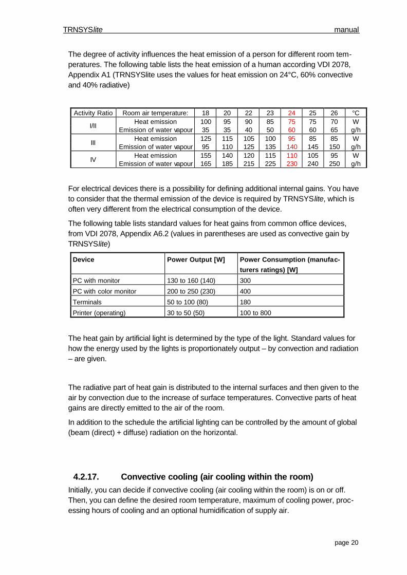
The degree of activity influences the heat emission of a person for different room tem-peratures. The following table lists the heat emission of a human according VDI 2078,Appendix A1 (TRNSYSlite uses the values for heat emission on 24°C, 60% convectiveand 40% radiative)
Activity Ratio Room air temperature: 18 20 22 23 24 25 26 °CHeat emission 100 95 90 85 75 75 70 W
I/IIEmission of water vapour 35 35 40 50 60 60 65 g/h
Heat emission 125 115 105 100 95 85 85 WIII
Emission of water vapour 95 110 125 135 140 145 150 g/hHeat emission 155 140 120 115 110 105 95 W
IVEmission of water vapour 165 185 215 225 230 240 250 g/h
For electrical devices there is a possibility for defining additional internal gains. You haveto consider that the thermal emission of the device is required by TRNSYSlite, which isoften very different from the electrical consumption of the device.
The following table lists standard values for heat gains from common office devices,from VDI 2078, Appendix A6.2 (values in parentheses are used as convective gain byTRNSYSlite)
Device Power Output [W] Power Consumption (manufac-
turers ratings) [W]
PC with monitor 130 to 160 (140) 300
PC with color monitor 200 to 250 (230) 400
Terminals 50 to 100 (80) 180
Printer (operating) 30 to 50 (50) 100 to 800
The heat gain by artificial light is determined by the type of the light. Standard values forhow the energy used by the lights is proportionately output – by convection and radiation– are given.
The radiative part of heat gain is distributed to the internal surfaces and then given to theair by convection due to the increase of surface temperatures. Convective parts of heatgains are directly emitted to the air of the room.
In addition to the schedule the artificial lighting can be controlled by the amount of global(beam (direct) + diffuse) radiation on the horizontal.
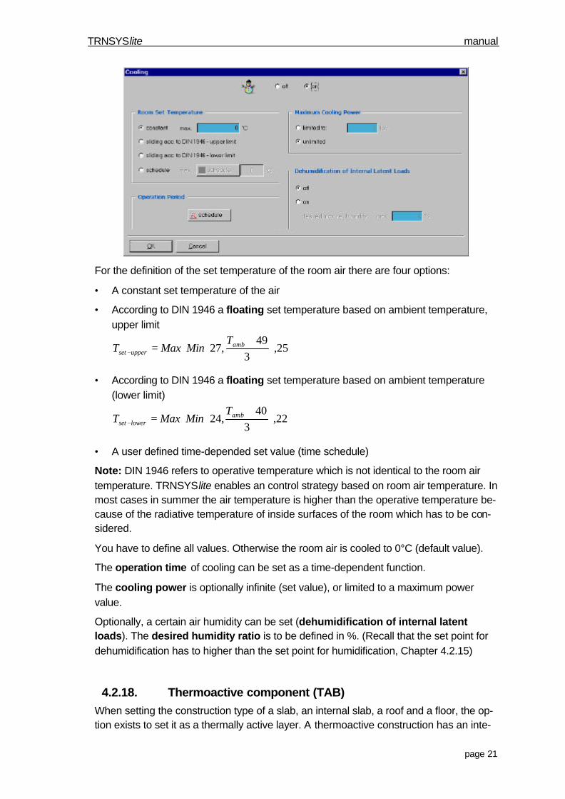
4.2.17. Convective cooling (air cooling within the room)Initially, you can decide if convective cooling (air cooling within the room) is on or off.Then, you can define the desired room temperature, maximum of cooling power, proc-essing hours of cooling and an optional humidification of supply air.
TRNSYSlite manual
page 21
For the definition of the set temperature of the room air there are four options:
• A constant set temperature of the air
• According to DIN 1946 a floating set temperature based on ambient temperature,upper limit
+=− 25,
349
,27 ambupperset
TMinMaxT
• According to DIN 1946 a floating set temperature based on ambient temperature(lower limit)
+=− 22,
340
,24 amblowerset
TMinMaxT
• A user defined time-depended set value (time schedule)
Note: DIN 1946 refers to operative temperature which is not identical to the room airtemperature. TRNSYSlite enables an control strategy based on room air temperature. Inmost cases in summer the air temperature is higher than the operative temperature be-cause of the radiative temperature of inside surfaces of the room which has to be con-sidered.
You have to define all values. Otherwise the room air is cooled to 0°C (default value).
The operation time of cooling can be set as a time-dependent function.
The cooling power is optionally infinite (set value), or limited to a maximum powervalue.
Optionally, a certain air humidity can be set (dehumidification of internal latentloads). The desired humidity ratio is to be defined in %. (Recall that the set point fordehumidification has to higher than the set point for humidification, Chapter 4.2.15)
4.2.18. Thermoactive component (TAB)When setting the construction type of a slab, an internal slab, a roof and a floor, the op-tion exists to set it as a thermally active layer. A thermoactive construction has an inte-
TRNSYSlite manual
page 22
grated array of water-filled pipes for heating and cooling. There are 2 types, dependingon the position of the pipe system:
• Cooling slabs (double-sided thick cover of massive layer, e.g. concrete)
• Floor heating (pipe system on an insulation layer)
For ceilings, roofs and internal slabs a thermoactive layer can be defined (the pipe sys-tem is situated in the middle of the concrete layer). For floors the setting of a floor heat-ing is possible. (The pipe system is backed by an insulation layer)
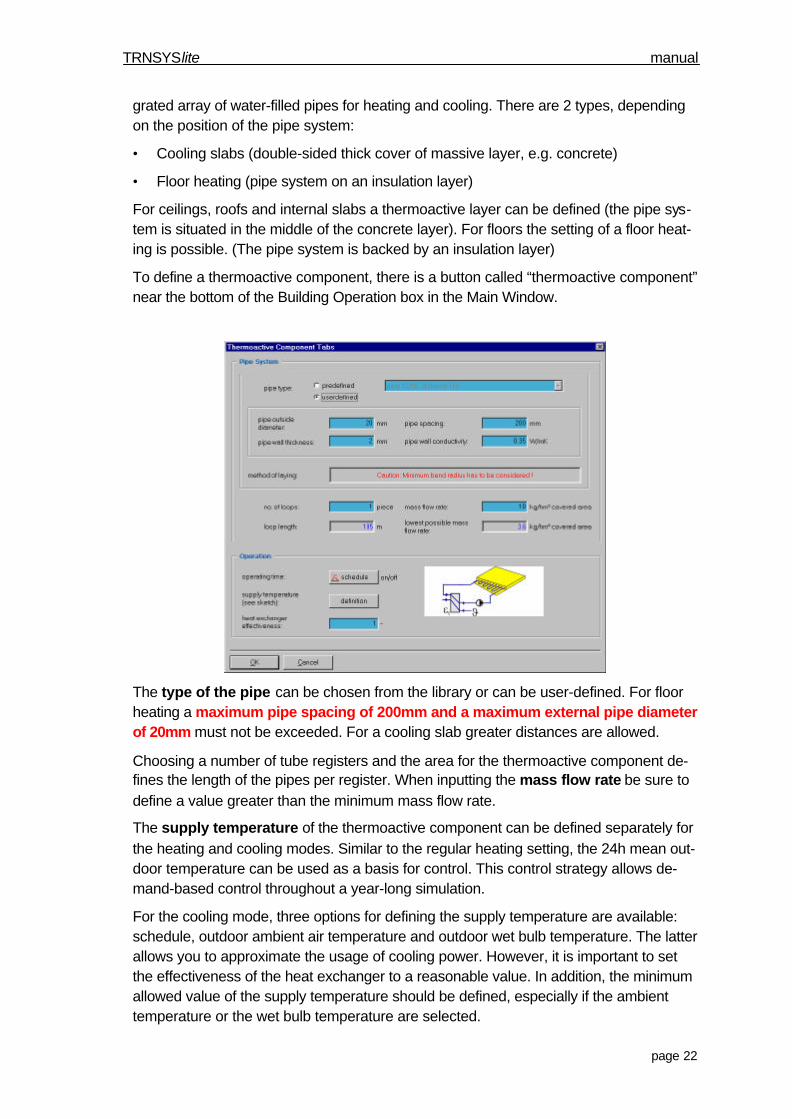
To define a thermoactive component, there is a button called “thermoactive component”near the bottom of the Building Operation box in the Main Window.
The type of the pipe can be chosen from the library or can be user-defined. For floorheating a maximum pipe spacing of 200mm and a maximum external pipe diameterof 20mm must not be exceeded. For a cooling slab greater distances are allowed.
Choosing a number of tube registers and the area for the thermoactive component de-fines the length of the pipes per register. When inputting the mass flow rate be sure todefine a value greater than the minimum mass flow rate.
The supply temperature of the thermoactive component can be defined separately forthe heating and cooling modes. Similar to the regular heating setting, the 24h mean out-door temperature can be used as a basis for control. This control strategy allows de-mand-based control throughout a year-long simulation.
For the cooling mode, three options for defining the supply temperature are available:schedule, outdoor ambient air temperature and outdoor wet bulb temperature. The latterallows you to approximate the usage of cooling power. However, it is important to setthe effectiveness of the heat exchanger to a reasonable value. In addition, the minimumallowed value of the supply temperature should be defined, especially if the ambienttemperature or the wet bulb temperature are selected.
TRNSYSlite manual
page 23
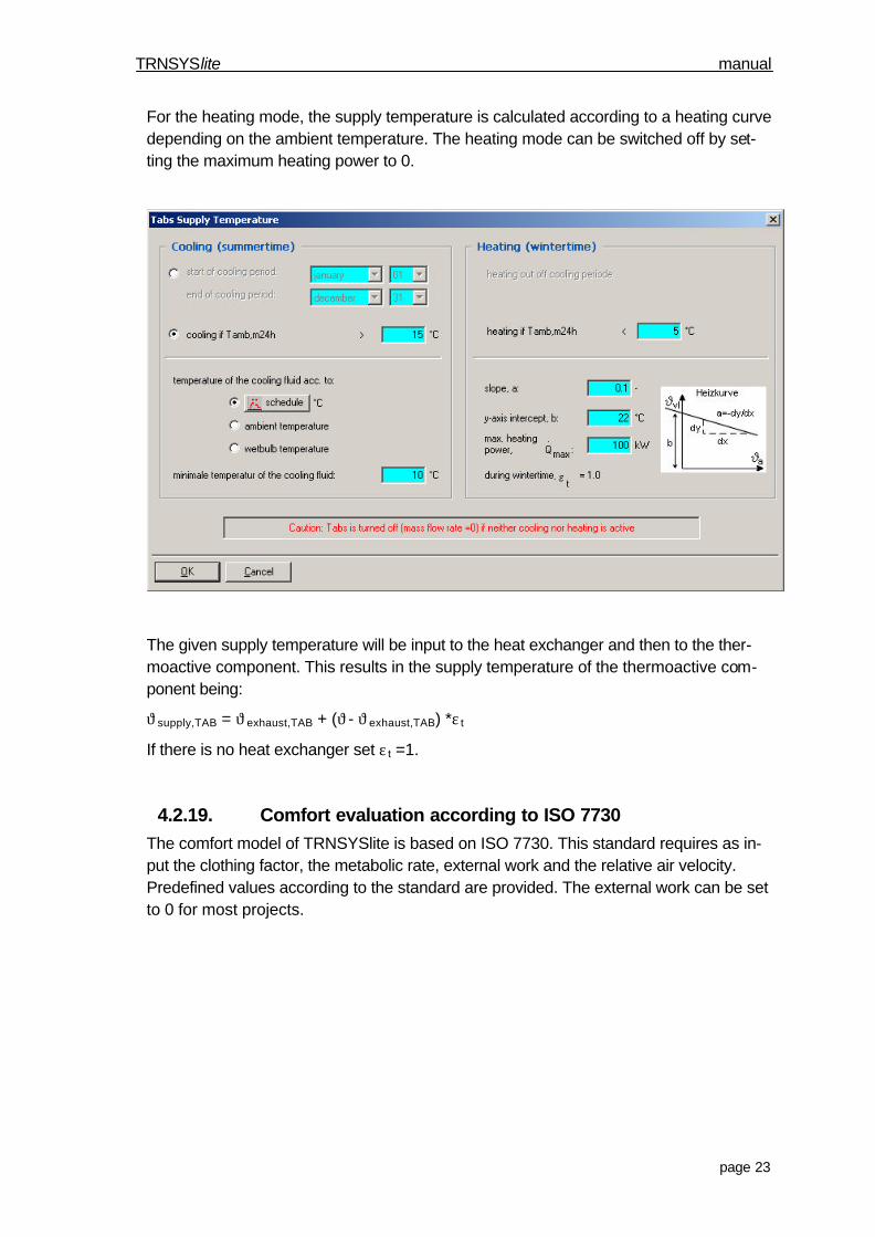
For the heating mode, the supply temperature is calculated according to a heating curvedepending on the ambient temperature. The heating mode can be switched off by set-ting the maximum heating power to 0.
The given supply temperature will be input to the heat exchanger and then to the ther-moactive component. This results in the supply temperature of the thermoactive com-ponent being:
ϑsupply,TAB = ϑexhaust,TAB + (ϑ- ϑexhaust,TAB) *ε t
If there is no heat exchanger set ε t =1.
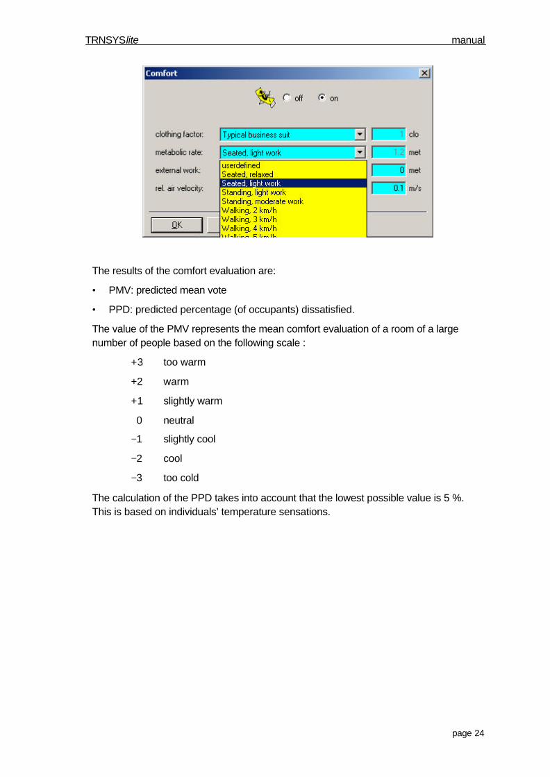
4.2.19. Comfort evaluation according to ISO 7730The comfort model of TRNSYSlite is based on ISO 7730. This standard requires as in-put the clothing factor, the metabolic rate, external work and the relative air velocity.Predefined values according to the standard are provided. The external work can be setto 0 for most projects.
TRNSYSlite manual
page 24
The results of the comfort evaluation are:
• PMV: predicted mean vote
• PPD: predicted percentage (of occupants) dissatisfied.
The value of the PMV represents the mean comfort evaluation of a room of a largenumber of people based on the following scale :
+3 too warm
+2 warm
+1 slightly warm
0 neutral
−1 slightly cool
−2 cool
−3 too cold
The calculation of the PPD takes into account that the lowest possible value is 5 %.This is based on individuals’ temperature sensations.
TRNSYSlite manual
page 25
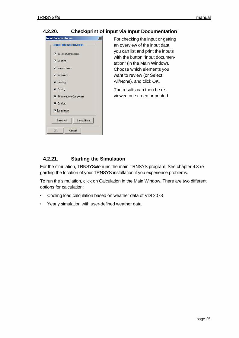
4.2.20. Check/print of input via Input DocumentationFor checking the input or gettingan overview of the input data,you can list and print the inputswith the button “input documen-tation” (in the Main Window).Choose which elements youwant to review (or SelectAll/None), and click OK.
The results can then be re-viewed on-screen or printed.
4.2.21. Starting the SimulationFor the simulation, TRNSYSlite runs the main TRNSYS program. See chapter 4.3 re-garding the location of your TRNSYS installation if you experience problems.
To run the simulation, click on Calculation in the Main Window. There are two differentoptions for calculation:
• Cooling load calculation based on weather data of VDI 2078
• Yearly simulation with user-defined weather data
TRNSYSlite manual
page 26
For both types of analyses the following settings should be defined:
• reference area for energy/power outputs for calculating specific values
• schedule for statistical analysis (for example, to create temperature statistics duringregular office hours, this schedule has to be set to the office hours)
• rotation of the thermal zone (the thermal zone can be rotated by any angle. Note thatthe angle is defined to be positive for a clockwise rotation.)
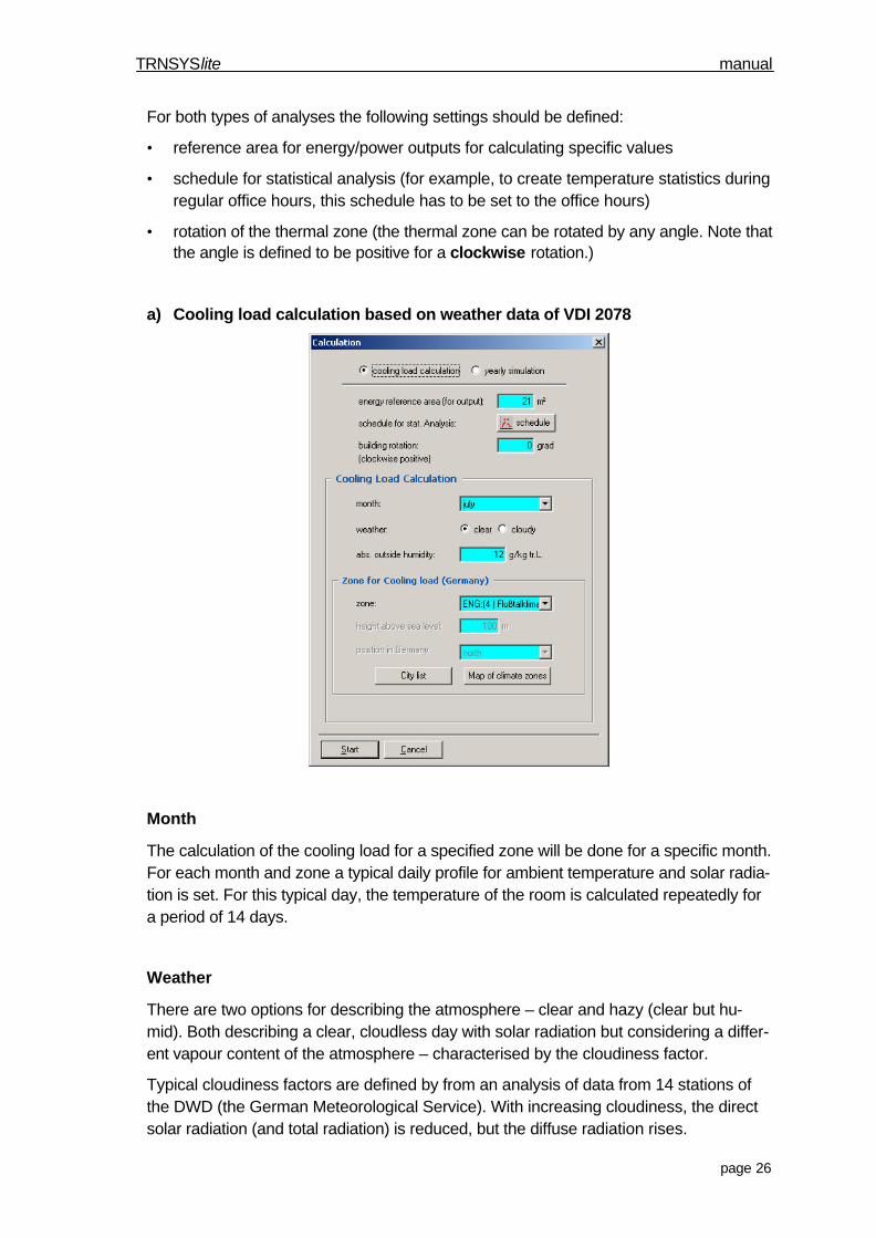
a) Cooling load calculation based on weather data of VDI 2078
Month
The calculation of the cooling load for a specified zone will be done for a specific month.For each month and zone a typical daily profile for ambient temperature and solar radia-tion is set. For this typical day, the temperature of the room is calculated repeatedly fora period of 14 days.
Weather
There are two options for describing the atmosphere – clear and hazy (clear but hu-mid). Both describing a clear, cloudless day with solar radiation but considering a differ-ent vapour content of the atmosphere – characterised by the cloudiness factor.
Typical cloudiness factors are defined by from an analysis of data from 14 stations ofthe DWD (the German Meteorological Service). With increasing cloudiness, the directsolar radiation (and total radiation) is reduced, but the diffuse radiation rises.
TRNSYSlite manual
page 27
The value of direct radiation is an important influence on the cooling load. In the case ofa significant influence on the cooling load caused by diffuse radiation (e.g. no shadingon north facade) you have to check your settings. Is the cooling load for cloudy weatherhigher than the cooling load for clear weather? This higher cooling load is valid forrooms with activated shading only for direct radiation.
Humidity of ambient air
The humidity ratio of the ambient air is only important for the calculation of the latentcooling load. Unfortunately, there is no data for humidity levels in VDI 2078. The sug-gested value is the maximum value expected at your location.
Zone for cooling load
The geographical location of the building corresponds to the appropriate zone for thecooling load. It can be set two ways: from a map of climate zones or from a list of cities.More information about the zones for cooling load can be found under chapter 5.1 .
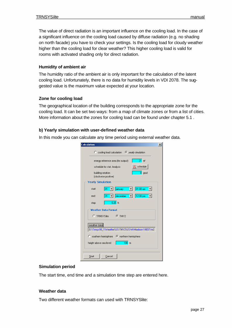
b) Yearly simulation with user-defined weather data
In this mode you can calculate any time period using external weather data.
Simulation period
The start time, end time and a simulation time step are entered here.
Weather data
Two different weather formats can used with TRNSYSlite:

TRNSYSlite manual
page 28
• TRNSYSlite format (see next page for description)• TMY2 format (new typical meteorological year, information can be found athttp://rredc.nrel.gov/solar/old_data/nsrdb/tmy2/)
In addition, the height above sea-level is required for calculating the air temperature.
A large variety of weather data is included in TRNSYS 16_1. In addition, TMY2 weatherfiles for various locations can be found on the internet.
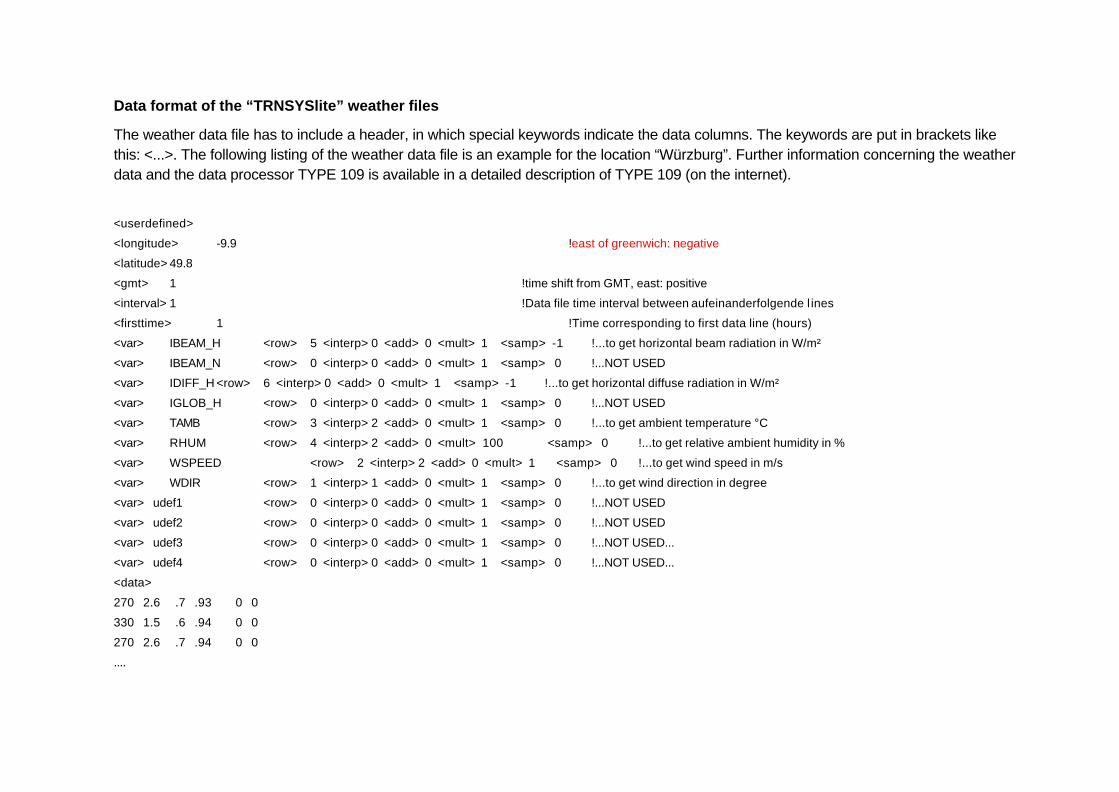
Data format of the “TRNSYSlite” weather files
The weather data file has to include a header, in which special keywords indicate the data columns. The keywords are put in brackets likethis: <...>. The following listing of the weather data file is an example for the location “Würzburg”. Further information concerning the weatherdata and the data processor TYPE 109 is available in a detailed description of TYPE 109 (on the internet).
<userdefined>
<longitude> -9.9 !east of greenwich: negative
<latitude> 49.8
<gmt> 1 !time shift from GMT, east: positive
<interval> 1 !Data file time interval between aufeinanderfolgende l ines
<firsttime> 1 !Time corresponding to first data line (hours)
<var> IBEAM_H <row> 5 <interp> 0 <add> 0 <mult> 1 <samp> -1 !...to get horizontal beam radiation in W/m²
<var> IBEAM_N <row> 0 <interp> 0 <add> 0 <mult> 1 <samp> 0 !...NOT USED
<var> IDIFF_H <row> 6 <interp> 0 <add> 0 <mult> 1 <samp> -1 !...to get horizontal diffuse radiation in W/m²
<var> IGLOB_H <row> 0 <interp> 0 <add> 0 <mult> 1 <samp> 0 !...NOT USED
<var> TAMB <row> 3 <interp> 2 <add> 0 <mult> 1 <samp> 0 !...to get ambient temperature °C
<var> RHUM <row> 4 <interp> 2 <add> 0 <mult> 100 <samp> 0 !...to get relative ambient humidity in %
<var> WSPEED <row> 2 <interp> 2 <add> 0 <mult> 1 <samp> 0 !...to get wind speed in m/s
<var> WDIR <row> 1 <interp> 1 <add> 0 <mult> 1 <samp> 0 !...to get wind direction in degree
<var> udef1 <row> 0 <interp> 0 <add> 0 <mult> 1 <samp> 0 !...NOT USED
<var> udef2 <row> 0 <interp> 0 <add> 0 <mult> 1 <samp> 0 !...NOT USED
<var> udef3 <row> 0 <interp> 0 <add> 0 <mult> 1 <samp> 0 !...NOT USED...
<var> udef4 <row> 0 <interp> 0 <add> 0 <mult> 1 <samp> 0 !...NOT USED...
<data>
270 2.6 .7 .93 0 0
330 1.5 .6 .94 0 0
270 2.6 .7 .94 0 0
....
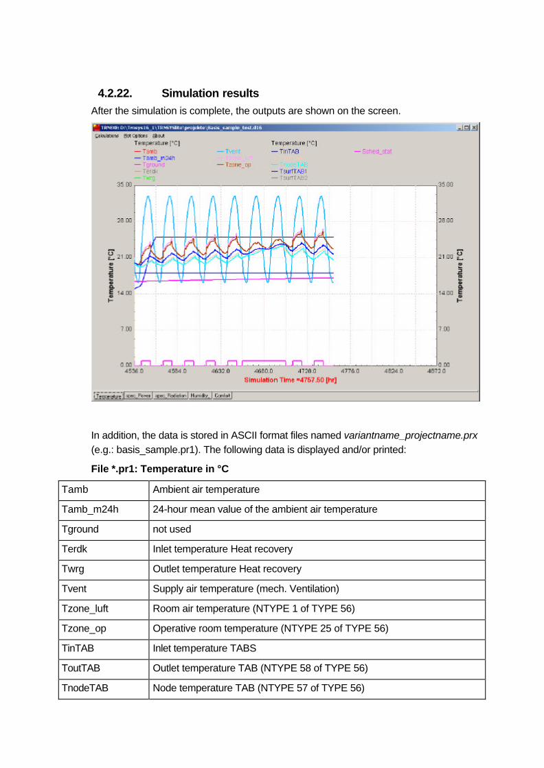
4.2.22. Simulation resultsAfter the simulation is complete, the outputs are shown on the screen.
In addition, the data is stored in ASCII format files named variantname_projectname.prx(e.g.: basis_sample.pr1). The following data is displayed and/or printed:
File *.pr1: Temperature in °C
Tamb Ambient air temperature
Tamb_m24h 24-hour mean value of the ambient air temperature
Tground not used
Terdk Inlet temperature Heat recovery
Twrg Outlet temperature Heat recovery
Tvent Supply air temperature (mech. Ventilation)
Tzone_luft Room air temperature (NTYPE 1 of TYPE 56)
Tzone_op Operative room temperature (NTYPE 25 of TYPE 56)
TinTAB Inlet temperature TABS
ToutTAB Outlet temperature TAB (NTYPE 58 of TYPE 56)
TnodeTAB Node temperature TAB (NTYPE 57 of TYPE 56)
TRNSYSlite manual
page 31
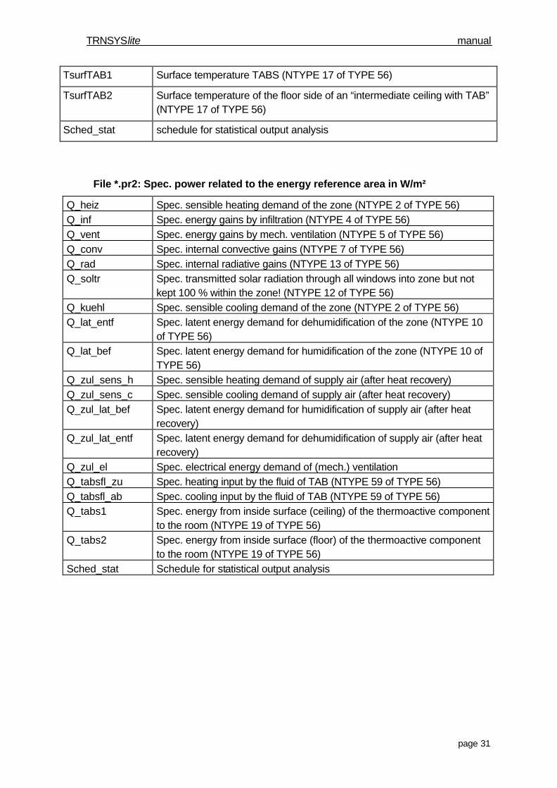
TsurfTAB1 Surface temperature TABS (NTYPE 17 of TYPE 56)
TsurfTAB2 Surface temperature of the floor side of an “intermediate ceiling with TAB”(NTYPE 17 of TYPE 56)
Sched_stat schedule for statistical output analysis
File *.pr2: Spec. power related to the energy reference area in W/m²
Q_heiz Spec. sensible heating demand of the zone (NTYPE 2 of TYPE 56)Q_inf Spec. energy gains by infiltration (NTYPE 4 of TYPE 56)Q_vent Spec. energy gains by mech. ventilation (NTYPE 5 of TYPE 56)Q_conv Spec. internal convective gains (NTYPE 7 of TYPE 56)Q_rad Spec. internal radiative gains (NTYPE 13 of TYPE 56)Q_soltr Spec. transmitted solar radiation through all windows into zone but not
kept 100 % within the zone! (NTYPE 12 of TYPE 56)Q_kuehl Spec. sensible cooling demand of the zone (NTYPE 2 of TYPE 56)Q_lat_entf Spec. latent energy demand for dehumidification of the zone (NTYPE 10
of TYPE 56)Q_lat_bef Spec. latent energy demand for humidification of the zone (NTYPE 10 of
TYPE 56)Q_zul_sens_h Spec. sensible heating demand of supply air (after heat recovery)Q_zul_sens_c Spec. sensible cooling demand of supply air (after heat recovery)Q_zul_lat_bef Spec. latent energy demand for humidification of supply air (after heat
recovery)Q_zul_lat_entf Spec. latent energy demand for dehumidification of supply air (after heat
recovery)Q_zul_el Spec. electrical energy demand of (mech.) ventilationQ_tabsfl_zu Spec. heating input by the fluid of TAB (NTYPE 59 of TYPE 56)Q_tabsfl_ab Spec. cooling input by the fluid of TAB (NTYPE 59 of TYPE 56)Q_tabs1 Spec. energy from inside surface (ceiling) of the thermoactive component
to the room (NTYPE 19 of TYPE 56)Q_tabs2 Spec. energy from inside surface (floor) of the thermoactive component
to the room (NTYPE 19 of TYPE 56)Sched_stat Schedule for statistical output analysis
TRNSYSlite manual
page 32
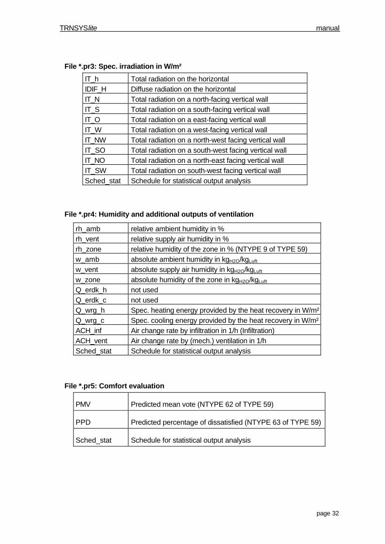
File *.pr3: Spec. irradiation in W/m²
IT_h Total radiation on the horizontalIDIF_H Diffuse radiation on the horizontalIT_N Total radiation on a north-facing vertical wallIT_S Total radiation on a south-facing vertical wallIT_O Total radiation on a east-facing vertical wallIT_W Total radiation on a west-facing vertical wallIT_NW Total radiation on a north-west facing vertical wallIT_SO Total radiation on a south-west facing vertical wallIT_NO Total radiation on a north-east facing vertical wallIT_SW Total radiation on south-west facing vertical wallSched_stat Schedule for statistical output analysis
File *.pr4: Humidity and additional outputs of ventilation
rh_amb relative ambient humidity in %rh_vent relative supply air humidity in %rh_zone relative humidity of the zone in % (NTYPE 9 of TYPE 59)w_amb absolute ambient humidity in kgH2O/kgLuft
w_vent absolute supply air humidity in kgH2O/kgLuft
w_zone absolute humidity of the zone in kgH2O/kgLuft
Q_erdk_h not usedQ_erdk_c not usedQ_wrg_h Spec. heating energy provided by the heat recovery in W/m²Q_wrg_c Spec. cooling energy provided by the heat recovery in W/m²ACH_inf Air change rate by infiltration in 1/h (Infiltration)ACH_vent Air change rate by (mech.) ventilation in 1/hSched_stat Schedule for statistical output analysis
File *.pr5: Comfort evaluation
PMV Predicted mean vote (NTYPE 62 of TYPE 59)
PPD Predicted percentage of dissatisfied (NTYPE 63 of TYPE 59)
Sched_stat Schedule for statistical output analysis
TRNSYSlite manual
page 33
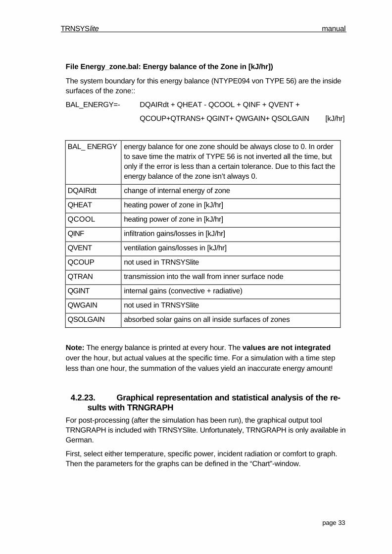
File Energy_zone.bal: Energy balance of the Zone in [kJ/hr])
The system boundary for this energy balance (NTYPE094 von TYPE 56) are the insidesurfaces of the zone::
BAL_ENERGY=- DQAIRdt + QHEAT - QCOOL + QINF + QVENT +
QCOUP+QTRANS+ QGINT+ QWGAIN+ QSOLGAIN [kJ/hr]
BAL_ ENERGY energy balance for one zone should be always close to 0. In orderto save time the matrix of TYPE 56 is not inverted all the time, butonly if the error is less than a certain tolerance. Due to this fact theenergy balance of the zone isn’t always 0.
DQAIRdt change of internal energy of zone
QHEAT heating power of zone in [kJ/hr]
QCOOL heating power of zone in [kJ/hr]
QINF infiltration gains/losses in [kJ/hr]
QVENT ventilation gains/losses in [kJ/hr]
QCOUP not used in TRNSYSlite
QTRAN transmission into the wall from inner surface node
QGINT internal gains (convective + radiative)
QWGAIN not used in TRNSYSlite
QSOLGAIN absorbed solar gains on all inside surfaces of zones
Note: The energy balance is printed at every hour. The values are not integratedover the hour, but actual values at the specific time. For a simulation with a time stepless than one hour, the summation of the values yield an inaccurate energy amount!
4.2.23. Graphical representation and statistical analysis of the re-sults with TRNGRAPH
For post-processing (after the simulation has been run), the graphical output toolTRNGRAPH is included with TRNSYSlite. Unfortunately, TRNGRAPH is only available inGerman.
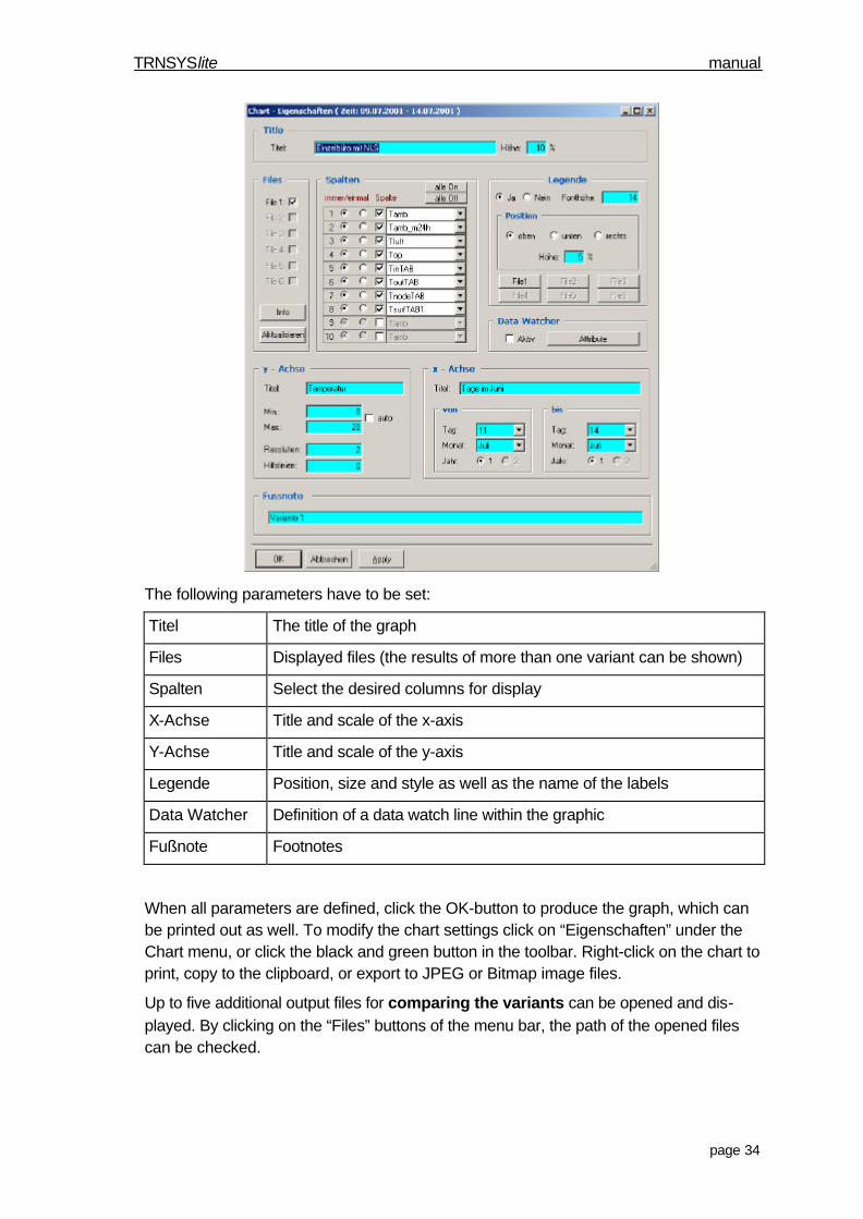
First, select either temperature, specific power, incident radiation or comfort to graph.Then the parameters for the graphs can be defined in the “Chart”-window.
TRNSYSlite manual
page 34
The following parameters have to be set:
Titel The title of the graph
Files Displayed files (the results of more than one variant can be shown)
Spalten Select the desired columns for display
X-Achse Title and scale of the x-axis
Y-Achse Title and scale of the y-axis
Legende Position, size and style as well as the name of the labels
Data Watcher Definition of a data watch line within the graphic
Fußnote Footnotes
When all parameters are defined, click the OK-button to produce the graph, which canbe printed out as well. To modify the chart settings click on “Eigenschaften” under theChart menu, or click the black and green button in the toolbar. Right-click on the chart toprint, copy to the clipboard, or export to JPEG or Bitmap image files.
Up to five additional output files for comparing the variants can be opened and dis-played. By clicking on the “Files” buttons of the menu bar, the path of the opened filescan be checked.
TRNSYSlite manual
page 35
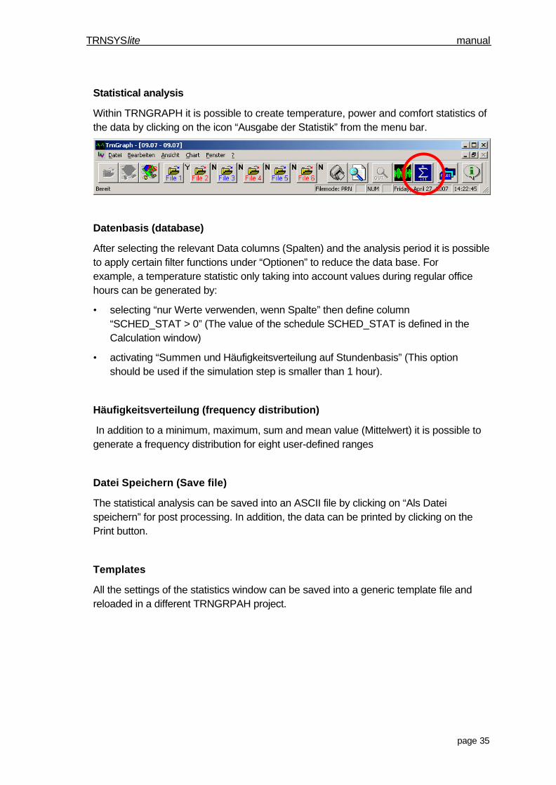
Statistical analysis
Within TRNGRAPH it is possible to create temperature, power and comfort statistics ofthe data by clicking on the icon “Ausgabe der Statistik” from the menu bar.
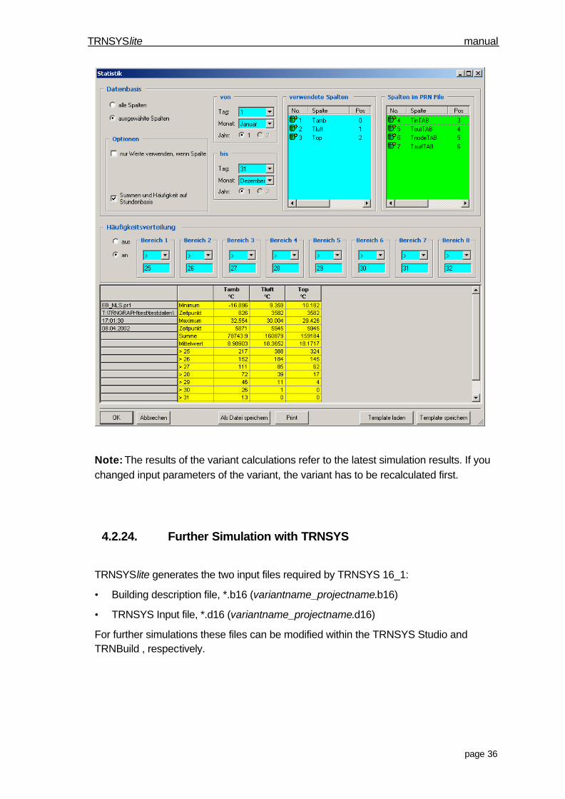
Datenbasis (database)
After selecting the relevant Data columns (Spalten) and the analysis period it is possibleto apply certain filter functions under “Optionen” to reduce the data base. Forexample, a temperature statistic only taking into account values during regular officehours can be generated by:
• selecting “nur Werte verwenden, wenn Spalte” then define column“SCHED_STAT > 0” (The value of the schedule SCHED_STAT is defined in theCalculation window)
• activating “Summen und Häufigkeitsverteilung auf Stundenbasis” (This optionshould be used if the simulation step is smaller than 1 hour).
Häufigkeitsverteilung (frequency distribution)
In addition to a minimum, maximum, sum and mean value (Mittelwert) it is possible togenerate a frequency distribution for eight user-defined ranges
Datei Speichern (Save file)
The statistical analysis can be saved into an ASCII file by clicking on “Als Dateispeichern” for post processing. In addition, the data can be printed by clicking on thePrint button.
Templates
All the settings of the statistics window can be saved into a generic template file andreloaded in a different TRNGRPAH project.
TRNSYSlite manual
page 36
Note: The results of the variant calculations refer to the latest simulation results. If youchanged input parameters of the variant, the variant has to be recalculated first.
4.2.24. Further Simulation with TRNSYS
TRNSYSlite generates the two input files required by TRNSYS 16_1:
• Building description file, *.b16 (variantname_projectname.b16)
• TRNSYS Input file, *.d16 (variantname_projectname.d16)
For further simulations these files can be modified within the TRNSYS Studio andTRNBuild , respectively.
TRNSYSlite manual
page 37
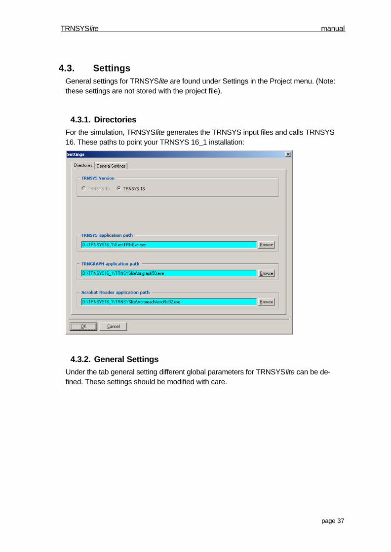
4.3. SettingsGeneral settings for TRNSYSlite are found under Settings in the Project menu. (Note:these settings are not stored with the project file).
4.3.1. DirectoriesFor the simulation, TRNSYSlite generates the TRNSYS input files and calls TRNSYS16. These paths to point your TRNSYS 16_1 installation:
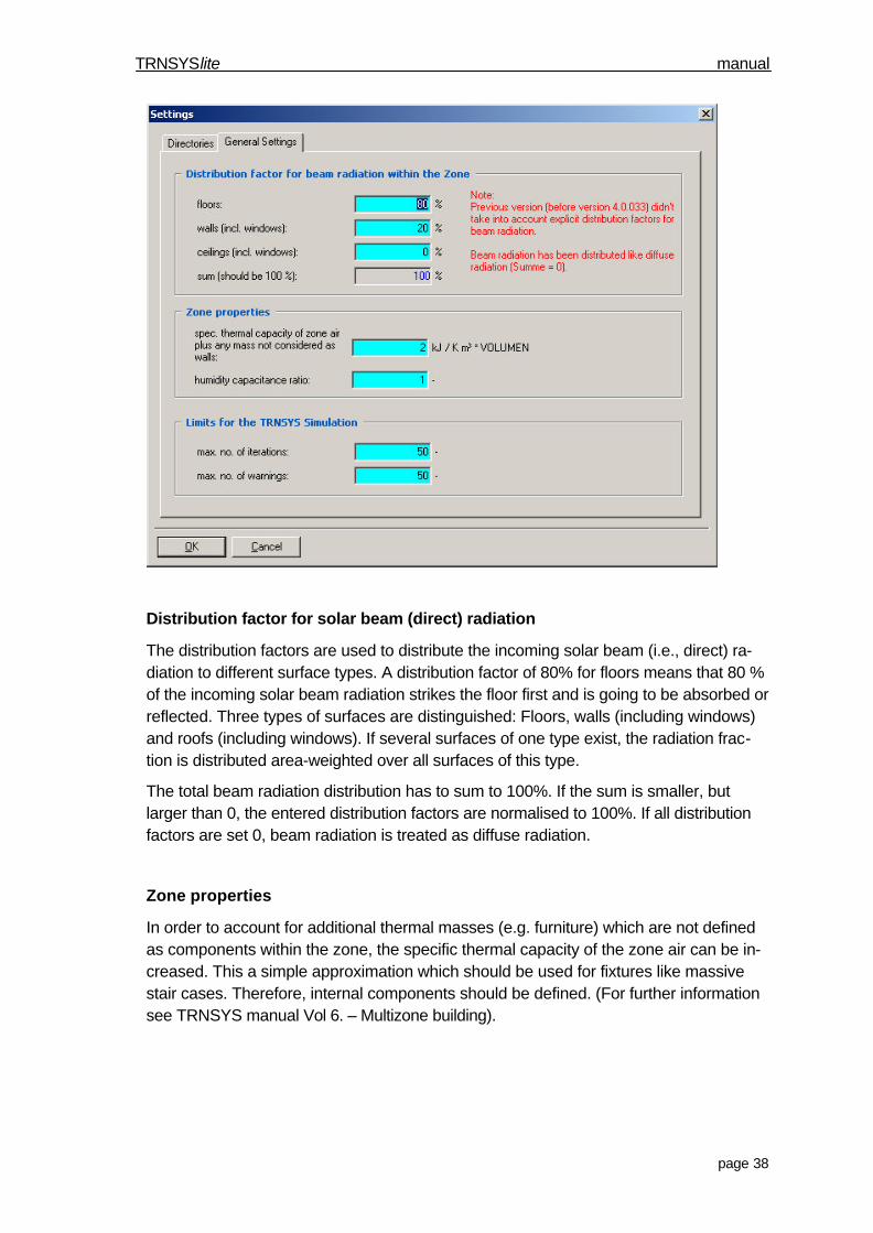
4.3.2. General SettingsUnder the tab general setting different global parameters for TRNSYSlite can be de-fined. These settings should be modified with care.
TRNSYSlite manual
page 38
Distribution factor for solar beam (direct) radiation
The distribution factors are used to distribute the incoming solar beam (i.e., direct) ra-diation to different surface types. A distribution factor of 80% for floors means that 80 %of the incoming solar beam radiation strikes the floor first and is going to be absorbed orreflected. Three types of surfaces are distinguished: Floors, walls (including windows)and roofs (including windows). If several surfaces of one type exist, the radiation frac-tion is distributed area-weighted over all surfaces of this type.
The total beam radiation distribution has to sum to 100%. If the sum is smaller, butlarger than 0, the entered distribution factors are normalised to 100%. If all distributionfactors are set 0, beam radiation is treated as diffuse radiation.
Zone properties
In order to account for additional thermal masses (e.g. furniture) which are not definedas components within the zone, the specific thermal capacity of the zone air can be in-creased. This a simple approximation which should be used for fixtures like massivestair cases. Therefore, internal components should be defined. (For further informationsee TRNSYS manual Vol 6. – Multizone building).

TRNSYSlite manual
page 39
Limits for the TRNSYS Simulation
The maximum number of iterations and warnings for the simulation can be definedhere. If these numbers are exceeded the simulation is terminated. In general, the defaultvalues are sufficient.
TRNSYSlite manual
page 40
5. Technical Information
5.1. Zones of cooling loads according VDI 2078According VDI 2078 the climate in Germany is divided into zones from 1 to 4. Zone 1aand 5 are special zones.
Zone 1 refers to the coastline, including the northern part of Schleswig-Holstein.
Zone 1a has identical weather data as Zone 1, refers to the low mountain range from200 – 600 m in the northern and western part and 700-1000 m in the southern andeastern part.
Zone 2 refers to the northern German lowlands, parts of the low mountain range, partsof Frankonia, Swabia, the Bay of Thuringia, the Oberlausitz and parts of the alpine up-land.
Zone 3 refers to the northern parts of the Rhine-lowlands, parts of Frankonia, Swabiaand Bavaria, a part of Lower Saxony north of Hannover up to Magdeburg, the Bay ofLeipzig and the Niederlausitz, as well as the environments of Berlin.
Zone 4 refers to the valleys of the rivers Rhein, Mosel, Main, Neckar, Elbe and Saale inthe low mountain range.
Zone 5 does not refer to a specific area of Germany. It is for the central mountain rangeover 600m (e.g. Kahler Asten, Rhön), and parts of the south and easterly low mountainrange above 1000 m (e.g. Schwarzwald, Bayrischer Wald, Erzgebirge).
For these parts of Germany the temperature and radiation data of zone 1 is used,where the outside air temperature is lowered according the height of the actual locationof the building:
For northern and western parts of Germany the outside temperature is lowered by theamount of the height of the location above 600 m
For southern parts of Germany the outside temperature is lowered by the amount of theheight of the location above 1000 m
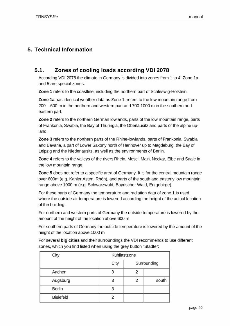
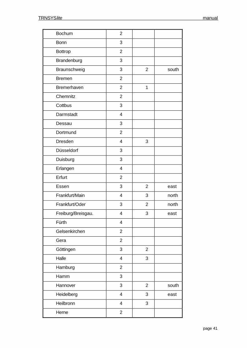
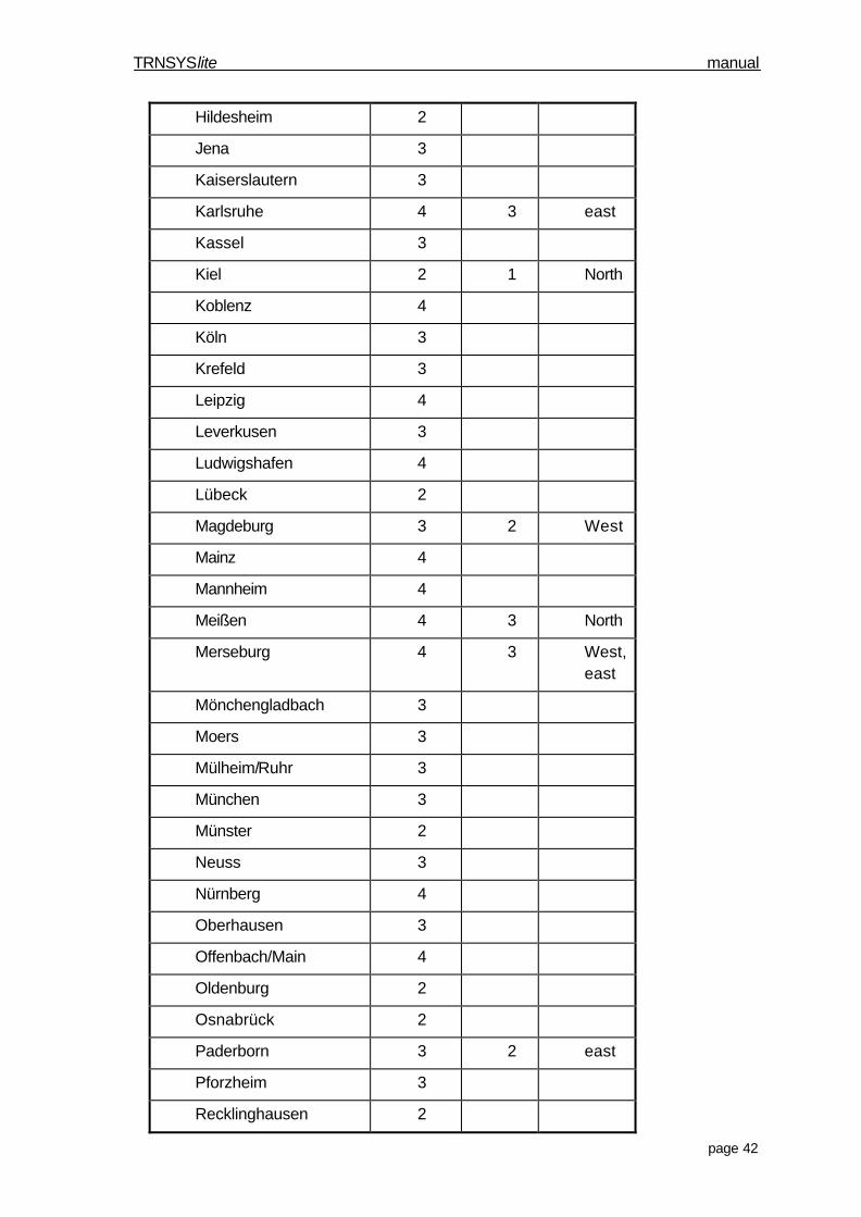
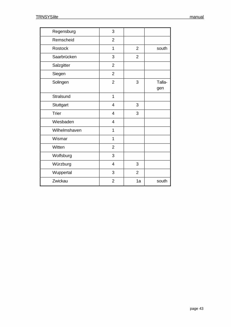
For several big cities and their surroundings the VDI recommends to use differentzones, which you find listed when using the grey button “Städte”:
City Kühllastzone
City Surrounding
Aachen 3 2
Augsburg 3 2 south
Berlin 3
Bielefeld 2
TRNSYSlite manual
page 41
Bochum 2
Bonn 3
Bottrop 2
Brandenburg 3
Braunschweig 3 2 south
Bremen 2
Bremerhaven 2 1
Chemnitz 2
Cottbus 3
Darmstadt 4
Dessau 3
Dortmund 2
Dresden 4 3
Düsseldorf 3
Duisburg 3
Erlangen 4
Erfurt 2
Essen 3 2 east
Frankfurt/Main 4 3 north
Frankfurt/Oder 3 2 north
Freiburg/Breisgau. 4 3 east
Fürth 4
Gelsenkirchen 2
Gera 2
Göttingen 3 2
Halle 4 3
Hamburg 2
Hamm 3
Hannover 3 2 south
Heidelberg 4 3 east
Heilbronn 4 3
Herne 2
TRNSYSlite manual
page 42
Hildesheim 2
Jena 3
Kaiserslautern 3
Karlsruhe 4 3 east
Kassel 3
Kiel 2 1 North
Koblenz 4
Köln 3
Krefeld 3
Leipzig 4
Leverkusen 3
Ludwigshafen 4
Lübeck 2
Magdeburg 3 2 West
Mainz 4
Mannheim 4
Meißen 4 3 North
Merseburg 4 3 West,east
Mönchengladbach 3
Moers 3
Mülheim/Ruhr 3
München 3
Münster 2
Neuss 3
Nürnberg 4
Oberhausen 3
Offenbach/Main 4
Oldenburg 2
Osnabrück 2
Paderborn 3 2 east
Pforzheim 3
Recklinghausen 2
TRNSYSlite manual
page 43
Regensburg 3
Remscheid 2
Rostock 1 2 south
Saarbrücken 3 2
Salzgitter 2
Siegen 2
Solingen 2 3 Talla-gen
Stralsund 1
Stuttgart 4 3
Trier 4 3
Wiesbaden 4
Wilhelmshaven 1
Wismar 1
Witten 2
Wolfsburg 3
Würzburg 4 3
Wuppertal 3 2
Zwickau 2 1a south
TRNSYSlite manual
page 44
5.2. Construction libraryThe result of a TRNSYSlite simulation contains the cooling and heating loads as well asthe resulting room temperatures for winter and summer. In addition to the constructionelements defined in the VDI, TRNSYSlite offers a construction library, which containsseveral typical constructions for walls, roofs, ceilings and floors in Germany.
The library was developed by the FH in Hamburg during a BMFT-project.
5.2.1. Construction typesSince it is not possible to present every construction type, these types are developed forthe construction library, which combine constructions with similar structure and similarthermal behaviour. This leads, for example, to the fact that the library does not containany steel constructions, because they are represented by the wooden constructions.
The basic classification of the library differs between massive and skeleton construc-tions. Concerning the heat capacity of the component further diversification has to bemade. The thermal behaviour of a massive external wall, for example, differs very muchdepending on if the insulation is attached to the outside or the inside of the wall (only forthe external insulated wall the room contains thermal mass to even the room tempera-tures), or if you choose a monolithic wall. For skeleton constructions, the fully glazedfacade is an exception, because it does not show any thermal mass at all.
5.2.2. Building materialsIt is also important to have a closer look to the used building materials. For the con-struction types described in the library, typical values for density and heat capacity arechosen based on manufacturers’ specifications.
TRNSYSlite manual
page 45
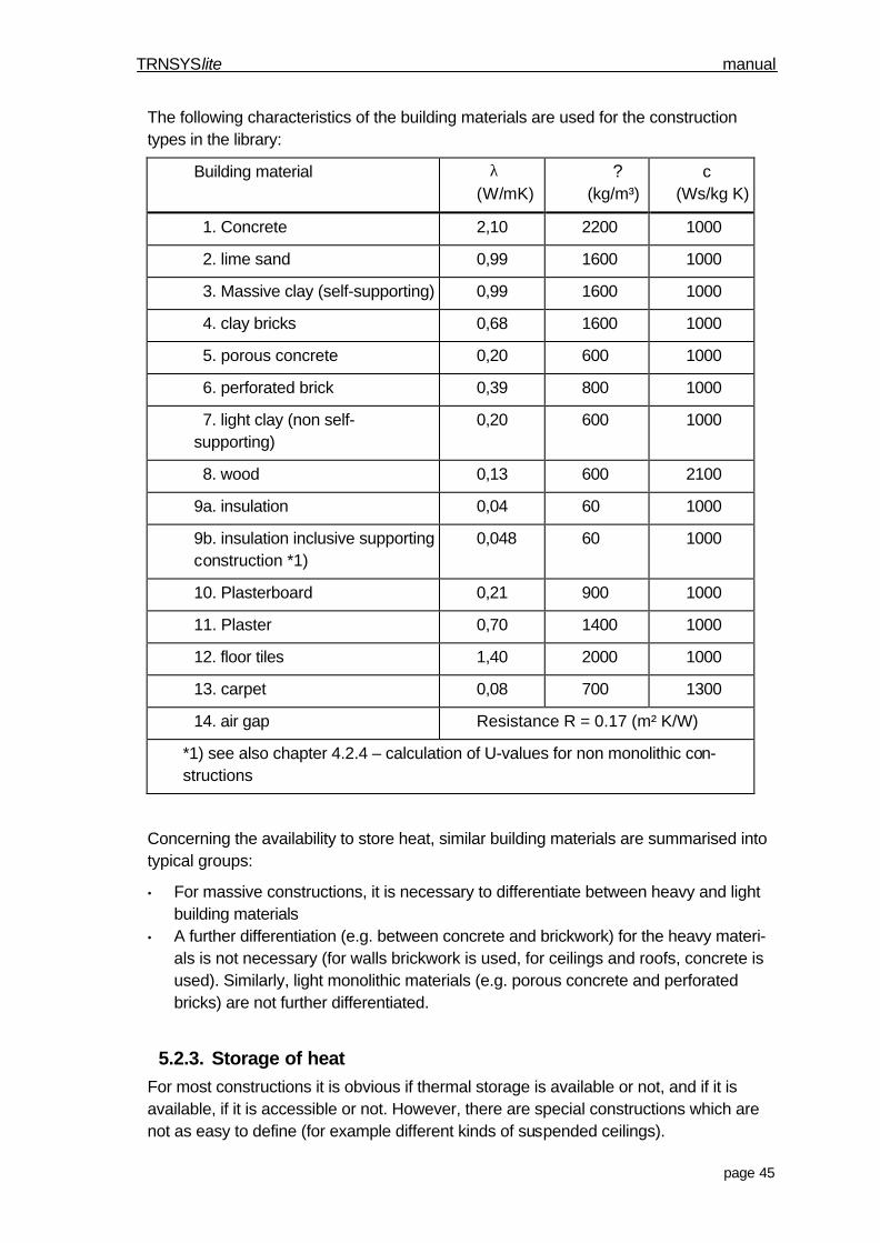
The following characteristics of the building materials are used for the constructiontypes in the library:
Building material λ(W/mK)
?(kg/m³)
c(Ws/kg K)
1. Concrete 2,10 2200 1000
2. lime sand 0,99 1600 1000
3. Massive clay (self-supporting) 0,99 1600 1000
4. clay bricks 0,68 1600 1000
5. porous concrete 0,20 600 1000
6. perforated brick 0,39 800 1000
7. light clay (non self-supporting)
0,20 600 1000
8. wood 0,13 600 2100
9a. insulation 0,04 60 1000
9b. insulation inclusive supportingconstruction *1)
0,048 60 1000
10. Plasterboard 0,21 900 1000
11. Plaster 0,70 1400 1000
12. floor tiles 1,40 2000 1000
13. carpet 0,08 700 1300
14. air gap Resistance R = 0.17 (m² K/W)
*1) see also chapter 4.2.4 – calculation of U-values for non monolithic con-structions
Concerning the availability to store heat, similar building materials are summarised intotypical groups:
• For massive constructions, it is necessary to differentiate between heavy and lightbuilding materials
• A further differentiation (e.g. between concrete and brickwork) for the heavy materi-als is not necessary (for walls brickwork is used, for ceilings and roofs, concrete isused). Similarly, light monolithic materials (e.g. porous concrete and perforatedbricks) are not further differentiated.
5.2.3. Storage of heatFor most constructions it is obvious if thermal storage is available or not, and if it isavailable, if it is accessible or not. However, there are special constructions which arenot as easy to define (for example different kinds of suspended ceilings).
TRNSYSlite manual
page 46
So even with a massive concrete ceiling, a suspended construction underneath theconcrete (e.g. for acoustic reasons) leads to a de-coupling of the thermal mass and theroom. The values for the effective heat capacity used in the library are taken from theVDI 2078. For simulation with TRNSYS, a more detailed model, using transfer-functions(see TRNSYS Reference Manual) is used.
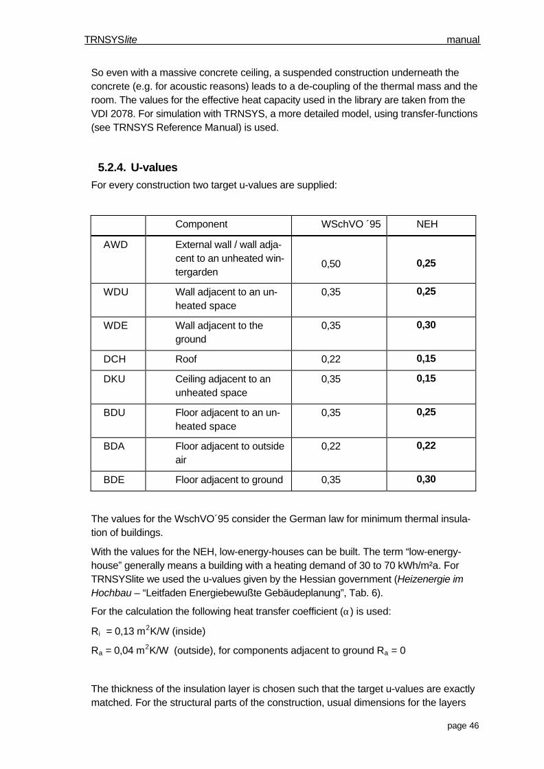
5.2.4. U-valuesFor every construction two target u-values are supplied:
Component WSchVO ´95 NEH
AWD External wall / wall adja-cent to an unheated win-tergarden
0,50 0,25
WDU Wall adjacent to an un-heated space
0,35 0,25
WDE Wall adjacent to theground
0,35 0,30
DCH Roof 0,22 0,15
DKU Ceiling adjacent to anunheated space
0,35 0,15
BDU Floor adjacent to an un-heated space
0,35 0,25
BDA Floor adjacent to outsideair
0,22 0,22
BDE Floor adjacent to ground 0,35 0,30
The values for the WschVO´95 consider the German law for minimum thermal insula-tion of buildings.
With the values for the NEH, low-energy-houses can be built. The term “low-energy-house” generally means a building with a heating demand of 30 to 70 kWh/m²a. ForTRNSYSlite we used the u-values given by the Hessian government (Heizenergie imHochbau – “Leitfaden Energiebewußte Gebäudeplanung”, Tab. 6).
For the calculation the following heat transfer coefficient (α) is used:
Ri = 0,13 m2K/W (inside)
Ra = 0,04 m2K/W (outside), for components adjacent to ground Ra = 0
The thickness of the insulation layer is chosen such that the target u-values are exactlymatched. For the structural parts of the construction, usual dimensions for the layers
TRNSYSlite manual
page 47
are used, so that the variation in the thickness of the insulation layer leads to a variationof the u-value. This sometimes leads to unusual dimensions of the insulation layer.since the constructions with theoretical layer dimensions act as substitutes for the ac-tual built construction, this is okay as long as the u-value and the effective thermal massare modelled correctly.
The above remark refers to the construction library and the calculation of the u-value inTRNSYSlite, not to the calculation in TRNSYS, which is an exact calculation done usingthe transfer function method (see TRNSYS Reference Manual)
Calculation of the u-value for non-monolithic constructions
The library contains building constructions, as shown in the sketches, which can bebuilt in a environmentally friendly way. The insulation layer is divided into the actual in-sulation and wood as supporting structure, which allows, for example, a constructionwith cellulose insulation material.
For the construction catalogue we assumed a fraction of wood of 11% for the construc-tion, which is a usual value for wooden constructions.
The calculation of the u-values for non-monolithic constructions follows the procedureof DIN 4108 (ISO 6946). The u-values of the structural part and insulative part are cal-culated separately, and then weighted by their fraction to a mean u-value for the wholeconstruction.
For TRNSYSlite a simplified method is used instead. The area which contains insulationand structural wood is modelled as a homogeneous layer with a heat conductivity of0.048 W/mK. For identical u-values this eventually leads to a slight difference of the di-mensions of the insulation layers.

TRNSYSlite manual
page 48
Apendix A: License Agreement
For the software tool TRNSYSlite of TRANSSOLAR Energietechnik GmbH
Note:
TRANSSOLAR grants you a license for the software on this CD-ROM, if the followingcontract is agreed upon. Please read the following conditions of the contract carefullybefore installing the software. By installing TRNSYSlite you agree all conditions of thecontract.
If you do not agree with the contract conditions, TRNSYSlite must not be installed andused. Return all transferred data media and documents for a refund from TRANSSOLAR.
1. With this contract you do not receive possession of the Software. The Software is ownedby TRANSSOLAR Energietechnik GmbH and the copyright is assured by international andnational law. If you agree with the license regulation, TRANSSOLAR grants you non-exclusive use of the software under the following conditions.
2. You have the right to use this program on only one computer at any given time. On whichcomputer you use this program is optional. Use in this case means every permanent ortemporary copy of the program as total or in parts due to saving, loading or displaying theprogram for executing the program and processing data, which is contained in the pro-gram by computers. You are also allowed to use the program to observe, study and testthe program.
You are allowed to make a copy of the Software for archival storage or to copy the soft-ware to your computers hard disk and store the original data media.
If the software is used in a computer network environment, every workstation, which hasaccess to the software via the network, needs a licensed copy.
It is allowed to change and process the program, if this is necessary for the use of theprogram, to connect the program to other software or to correct errors. It is not allowed tochange Company names, logos, copyrights and further remarks contained in the pro-gram.
TRNSYSlite manual
page 49
The user manual, which is delivered on data media is allowed to be printed out only onceand is allowed to be used only at one licensed workstation. It is not allowed to producefurther copies.
It is not allowed to lend or to rent out the software or parts of it or to assign further li-censes.
It is not allowed to decompile or disassemble the program back to its source code or tomake the source code assessable in any other way, apart from §69 e UrhG.
It is not allowed to change the software, to translate it or to develop derivative products.
3. All rights for using the software stay with TRANSSOLAR. The licensee is not allowed touse the software or derivatives of the software on more than one computer or publishcopies of the software or its derivatives, even if these copies contain a changed form ofthe original program. The license has the exploration right for own programs, which aredeveloped or used by using the software and for the results, which are reached by usingthe software.
4. Limited warranty
TRANSSOLAR ensures for a time period of 60 days up from the date of receipt, that themedium, on which the software is delivered, has no material or processing defects andthat the original program is recorded on a tested data medium. If such a defect occurs,you are entitled to get a substitute of the program on a new, tested data media.
Further warranty is not assumed. Especially, TRANSSOLAR is not responsible for thesuitability of the program for your intended use. Further, TRANSSOLAR does not warrantthat the program is compatible with your computer hardware or other programs used onyour computer.
TRANSSOLAR takes adequate care that the information and perception delivered withinthis software corresponds to the actual state of the art. However, TRANSSOLAR does notwarrant the correctness of the content. Furthermore – like all computer programs – it isnot guaranteed that the software works correctly for all applications.
In particular TRANSSOLAR does not guarantee that the software meets the special re-quests of the licensee or the user. The licensee is fully responsible for the choice, the in-stallation and the use of the program, as well as for the results of the calculations. Fur-

TRNSYSlite manual
page 50
thermore we do not assume any warranty for changed or processed versions of the pro-gram.
TRANSSOLAR does not assume the warranty that copy rights of third are injured.
TRANSSOLAR does not liable for direct or indirect damages, including escaped benefit,escaped savings or the loss of data. This applies as well, if TRANSSOLAR was explicitlyindicated of these kind of damages. Further, liability for claims of third persons is ex-cluded.
This exclusion of liability does not apply for damages, which are caused by intention orgross carelessness. As well, claims due to the law of product liability stay unaffected.
If the exclusion of liability cannot by applied, TRANSSOLAR is liable only for damages upto the price of the software.
The laws of Germany are applied to this license regulation (with exception of the applica-tion of the collision right). That UN come over contracts for the international goods pur-chase, the uniform law over the conclusion of international sales contracts or mobilethings and the uniform law over the international purchase of mobile things, any laws,regulations or regulations of any justice system, which are based on the conventions tothe mentioned or uniform laws, and which are application of these conventions and uni-form law as well as the application of any laws, regulations or regulations of any justicesystem, which are based on it, hereby are explicit excluded.
This agreement can be changed only by an additional license agreement delivered withthis license or by another, both by you and TRANSSOLAR signed written document.
TRANSSOLAR Energietechnik GmbHTechnologien zur rationellen Energienutzung undSolartechnikCuriestraße 2D-70563 StuttgartFax: +49/ 711 / 67976 - 11e-mail: [email protected]