Pd-catalyzed stereoselective tandem ring-opening amination ...
Upload
frederick-higginsCategory
view
232download
0
TRENDS IN BPM SYSTEM DESIGNThe ATF Damping Ring BPM Upgrade
Nathan EddyManfred Wendt
Fermilab
Low-ε-Ring Workshop 2011
Heraklion, Crete, Greece
Page 2October 5, 2011 – LER 2011 – N. Eddy & M. Wendt
Contents
• Part I (Manfred)– Introduction– BPM Pickup Design
“Button-style” BPM– Read-out Electronics
• Part II (Nathan)– The ATF DR BPM System
Page 3October 5, 2011 – LER 2011 – N. Eddy & M. Wendt
BPM Building Blocks
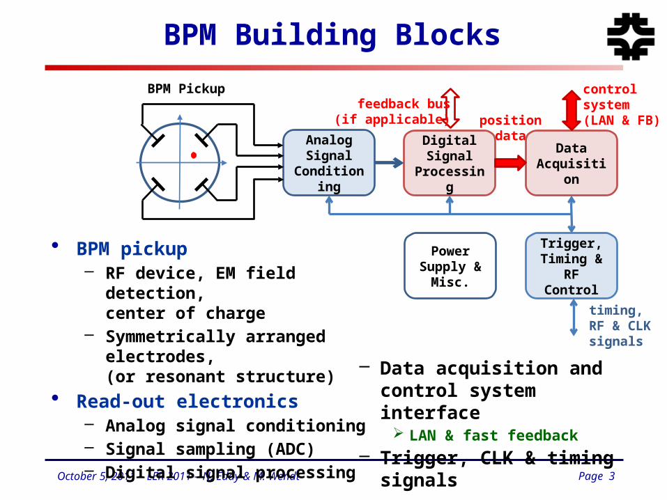
• BPM pickup– RF device, EM field detection,
center of charge– Symmetrically arranged electrodes,
(or resonant structure)
• Read-out electronics– Analog signal conditioning– Signal sampling (ADC)– Digital signal processing
Analog Signal
Conditioning
Digital Signal Processing
Data Acquisition
Trigger, Timing & RF
Control
Power Supply &
Misc.
BPM Pickup
positiondata
controlsystem(LAN & FB)
timing,RF & CLKsignals
feedback bus(if applicable)
– Data acquisition and control system interface
LAN & fast feedback
– Trigger, CLK & timing signals
Page 4October 5, 2011 – LER 2011 – N. Eddy & M. Wendt
Beam Structure
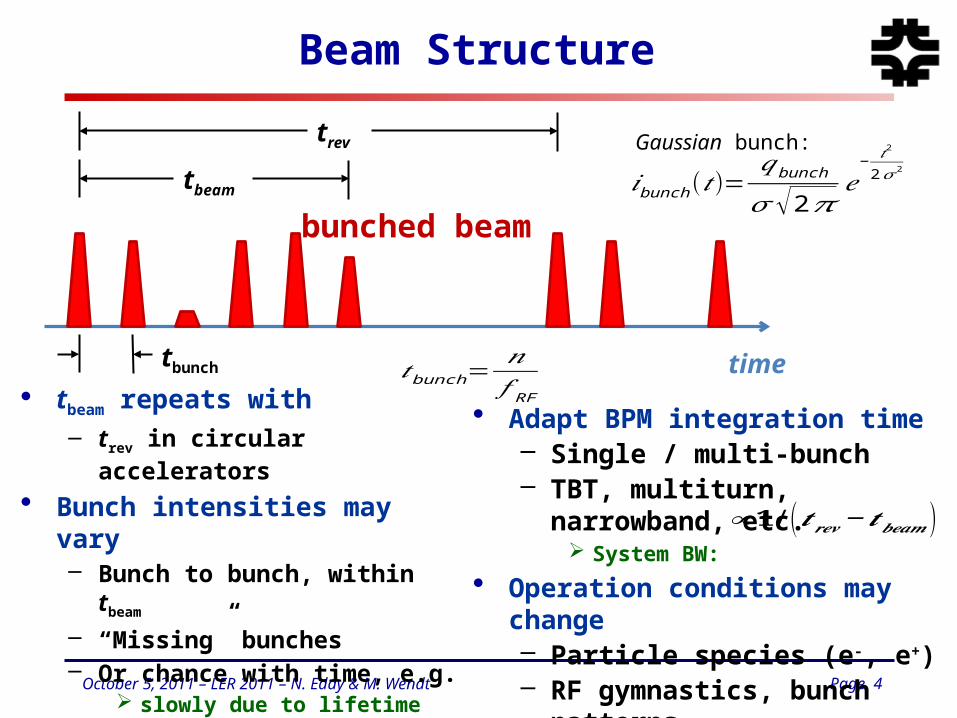
• tbeam repeats with– trev in circular accelerators
• Bunch intensities may vary– Bunch to bunch, within tbeam
– “Missing” bunches– Or chance with time, e.g.
slowly due to lifetime fast due to top-up injection
• Adapt BPM integration time– Single / multi-bunch– TBT, multiturn, narrowband,
etc. System BW:
• Operation conditions may change– Particle species (e-, e+)– RF gymnastics, bunch
patterns,…
𝑖bunch (𝑡)=𝑞bunch
𝜎 √2𝜋𝑒
− 𝑡2
2 𝜎2
tbunch
trev
time
bunched beam
tbeam
𝑡 bunch=𝑛𝑓 RF
Gaussian bunch:
∝𝟏 / (𝒕𝒓𝒆𝒗−𝒕𝒃𝒆𝒂𝒎 )
Page 5October 5, 2011 – LER 2011 – N. Eddy & M. Wendt
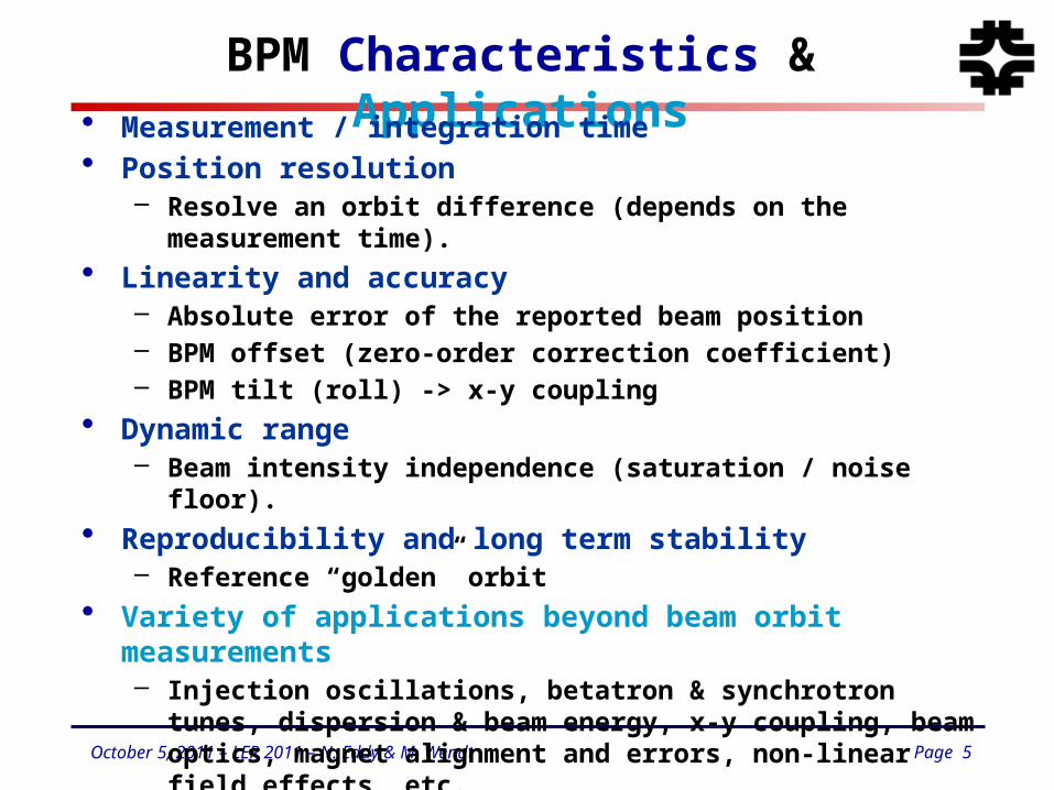
BPM Characteristics & Applications• Measurement / integration time• Position resolution
– Resolve an orbit difference (depends on the measurement time).
• Linearity and accuracy– Absolute error of the reported beam position– BPM offset (zero-order correction coefficient) – BPM tilt (roll) -> x-y coupling
• Dynamic range– Beam intensity independence (saturation / noise floor).
• Reproducibility and long term stability– Reference “golden” orbit
• Variety of applications beyond beam orbit measurements– Injection oscillations, betatron & synchrotron tunes, dispersion
& beam energy, x-y coupling, beam optics, magnet alignment and errors, non-linear field effects, etc.
– Machine commissioning (intensity).
Page 6October 5, 2011 – LER 2011 – N. Eddy & M. Wendt
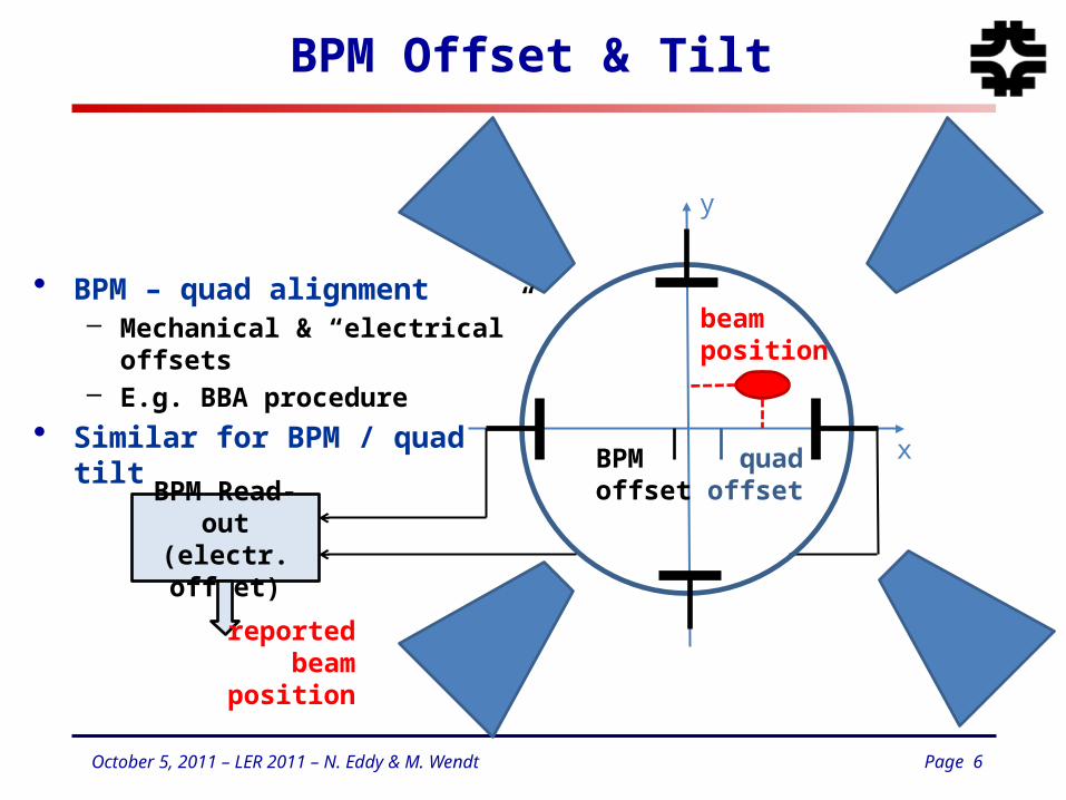
BPM Offset & Tilt
BPM Read-out(electr. offset)
x
y
BPMoffset
quadoffset
beamposition
reportedbeam
position
• BPM – quad alignment– Mechanical & “electrical” offsets– E.g. BBA procedure
• Similar for BPM / quad tilt
Page 7October 5, 2011 – LER 2011 – N. Eddy & M. Wendt
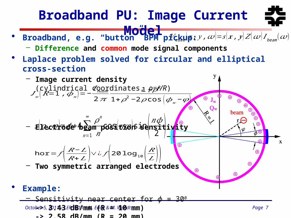
Broadband PU: Image Current Model
• Broadband, e.g. “button” BPM pickup:– Difference and common mode signal components
• Laplace problem solved for circular and elliptical cross-section– Image current density
(cylindrical coordinates, ρ=r/R)
– Electrode beam position sensitivity
– Two symmetric arranged electrodes
• Example: – Sensitivity near center for ϕ = 300
-> 3.43 dB/mm (R = 10 mm)-> 2.58 dB/mm (R = 20 mm)
𝐽𝑤 (𝑅=1 ,𝜙𝑤 )=−𝐼𝑏𝑒𝑎𝑚2𝜋
1−𝜌2
1+𝜌2−2 𝜌 cos (𝜙𝑤−𝜑 )
𝑠 (𝜌 ,𝜑 )=𝜙+4∑𝑛=1
∞ 𝜌𝑛
𝑛cos (𝑛𝜑 )sin (𝑛𝜙2 )
hor= 𝑓 (𝑅−𝐿𝑅+𝐿 )∨¿ 𝑓 (20 log10(𝑅𝐿 ))
𝑉 elec (𝑥 , 𝑦 ,𝜔 )=𝑠 (𝒙 ,𝒚 )𝑍 (𝜔 ) 𝐼beam(𝜔)
Page 8October 5, 2011 – LER 2011 – N. Eddy & M. Wendt
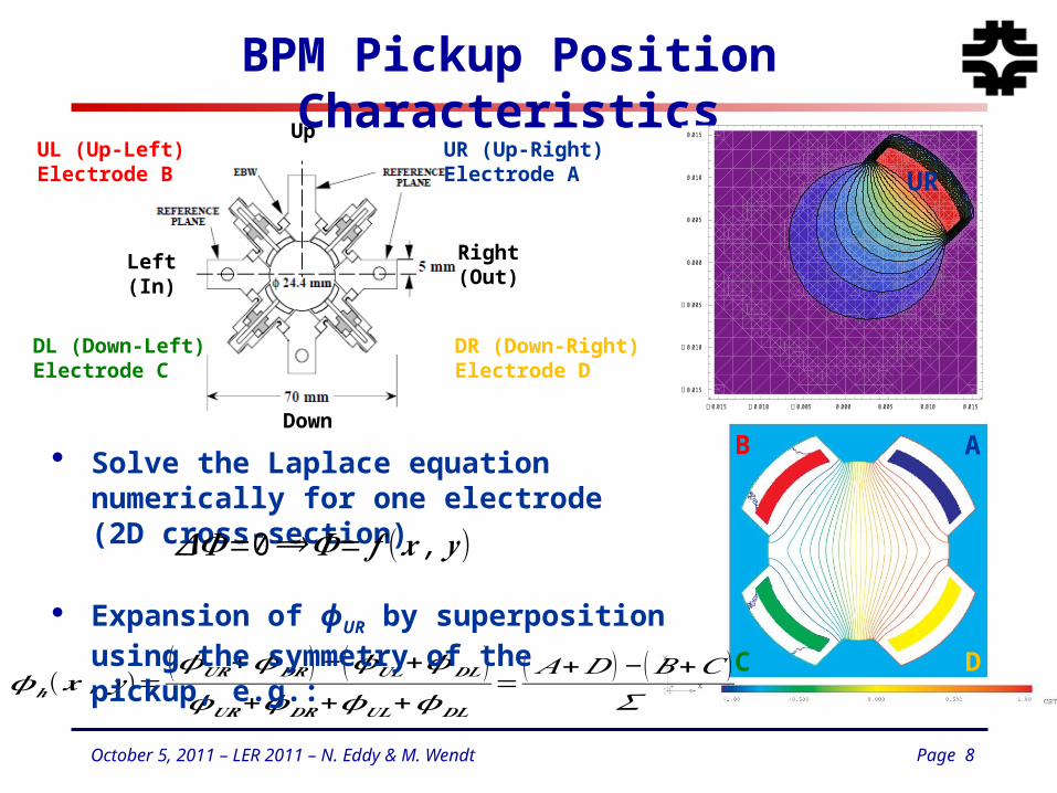
BPM Pickup Position Characteristics
Up
Down
Right(Out)
Left(In)
UR (Up-Right)Electrode A
DR (Down-Right)Electrode D
DL (Down-Left)Electrode C
UL (Up-Left)Electrode B
0.015 0.010 0.005 0.000 0.005 0.010 0.015
0.015
0.010
0.005
0.000
0.005
0.010
0.015
𝝓𝒉(𝒙 , 𝒚 )=(𝝓𝑼𝑹+𝝓𝑫𝑹) − (𝝓𝑼𝑳+𝝓𝑫𝑳 )𝝓𝑼𝑹+𝝓𝑫𝑹+𝝓𝑼𝑳+𝝓𝑫𝑳
=(𝐴+𝐷 ) − (𝐵+𝐶 )
𝛴
• Solve the Laplace equation numerically for one electrode (2D cross-section)
• Expansion of ϕUR by superposition using the symmetry of the pickup, e.g.:
𝜟𝜱=0⟹𝜱= 𝒇 (𝒙 ,𝒚 )
UR
AB
C D
Page 9October 5, 2011 – LER 2011 – N. Eddy & M. Wendt
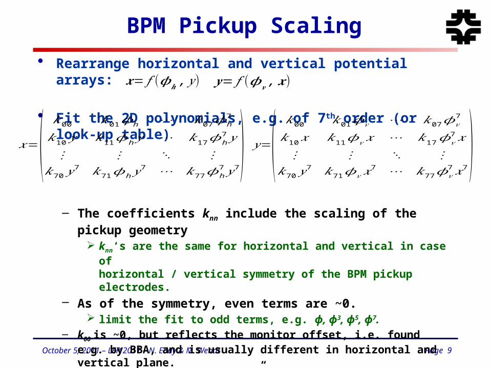
BPM Pickup Scaling
• Rearrange horizontal and vertical potential arrays:
• Fit the 2D polynomials, e.g. of 7th order (or look-up table)
– The coefficients knn include the scaling of the pickup geometry knn‘s are the same for horizontal and vertical in case of
horizontal / vertical symmetry of the BPM pickup electrodes.– As of the symmetry, even terms are ~0.
limit the fit to odd terms, e.g. ϕ, ϕ3, ϕ5, ϕ7.– k00 is ~0, but reflects the monitor offset, i.e. found e.g. by BBA, and is
usually different in horizontal and vertical plane.– k01 is the “monitor constant”, slope at the origin
• BPM pickup scaling and non-linear field correction:– Iterate a few times:
𝑥=(𝑘00 𝑘01𝜙h ⋯ 𝑘07𝜙h
7
𝑘10 𝑦 𝑘11𝜙h 𝑦 ⋯ 𝑘17𝜙h7 𝑦
⋮ ⋮ ⋱ ⋮𝑘70 𝑦
7 𝑘71𝜙h 𝑦7 ⋯ 𝑘77𝜙h
7 𝑦7)
𝒙= 𝑓 (𝝓𝒉 , 𝑦 ) 𝒚= 𝑓 (𝝓𝒗 ,𝒙 )
𝑦=(𝑘00 𝑘01𝜙𝑣 ⋯ 𝑘07𝜙𝑣
7
𝑘10𝑥 𝑘11𝜙𝑣 𝑥 ⋯ 𝑘17𝜙𝑣7 𝑥
⋮ ⋮ ⋱ ⋮𝑘70 𝑦
7 𝑘71𝜙𝑣𝑥7 ⋯ 𝑘77𝜙𝑣
7 𝑥7)
Page 10October 5, 2011 – LER 2011 – N. Eddy & M. Wendt
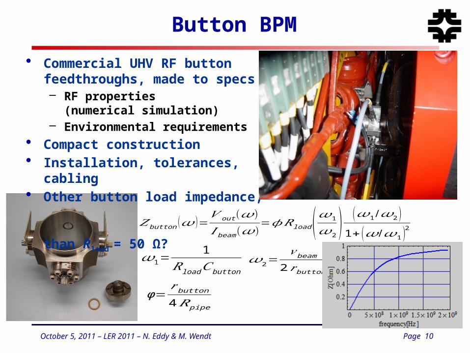
Button BPM
𝑍 button (𝜔 )=𝑉 out (𝜔)𝐼 beam(𝜔)
=𝜙𝑅load (𝜔1𝜔2 )(𝜔1/𝜔2 )1+ (𝜔 /𝜔1 )2
• Commercial UHV RF button feedthroughs, made to specs– RF properties
(numerical simulation)– Environmental requirements
• Compact construction• Installation, tolerances, cabling• Other button load impedance,
than Rload = 50 Ω?
𝜔1=1
𝑅load𝐶button𝜔2=𝑣beam
2𝑟button
ϕ=𝑟button
4𝑅 pipe
Page 11October 5, 2011 – LER 2011 – N. Eddy & M. Wendt
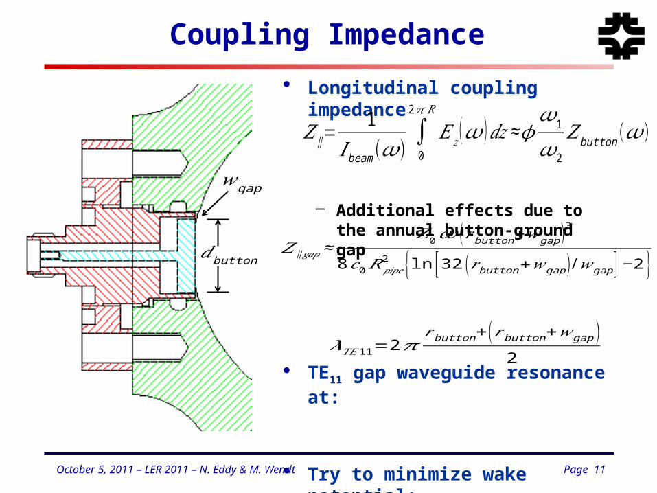
Coupling Impedance
• Longitudinal coupling impedance
– Additional effects due to the annual button-ground gap
• TE11 gap waveguide resonance at:
• Try to minimize wake potential:– Reduce rbutton
– Minimize wgap
𝑍∥=1
𝐼 beam(𝜔) ∫02𝜋 𝑅
𝐸𝑧 (𝜔 )𝑑𝑧≈𝜙𝜔1𝜔2𝑍button(𝜔)
𝑍∥ 𝑔𝑎𝑝≈𝑍0𝜔 (𝑟 button+𝑤gap )3
8𝑐0𝑅𝑝𝑖𝑝𝑒2 {ln [32 (𝑟button+𝑤gap )/𝑤gap ]−2}
𝜆𝑇𝐸11=2𝜋𝑟button+(𝑟button+𝑤gap )
2
𝑑button
𝑤gap
Page 12October 5, 2011 – LER 2011 – N. Eddy & M. Wendt
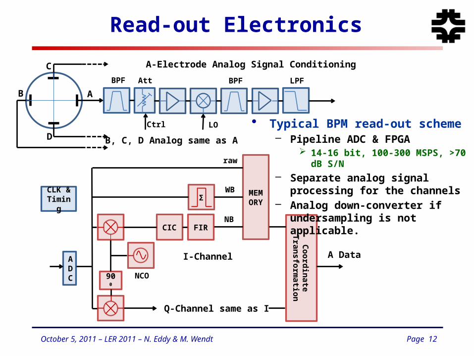
Read-out Electronics
ADC 900
CIC FIR
ΣMEMORY
NCO
I-Channel
Q-Channel same as I
NB
WB
raw
AB
C
D
BPF Att BPF LPF
CoordinateTransform
ation
A-Electrode Analog Signal Conditioning
B, C, D Analog same as A
Ctrl LO
CLK & Timing
A Data
• Typical BPM read-out scheme– Pipeline ADC & FPGA
14-16 bit, 100-300 MSPS, >70 dB S/N
– Separate analog signal processing for the channels
– Analog down-converter if undersampling is not applicable.
Page 13October 5, 2011 – LER 2011 – N. Eddy & M. Wendt
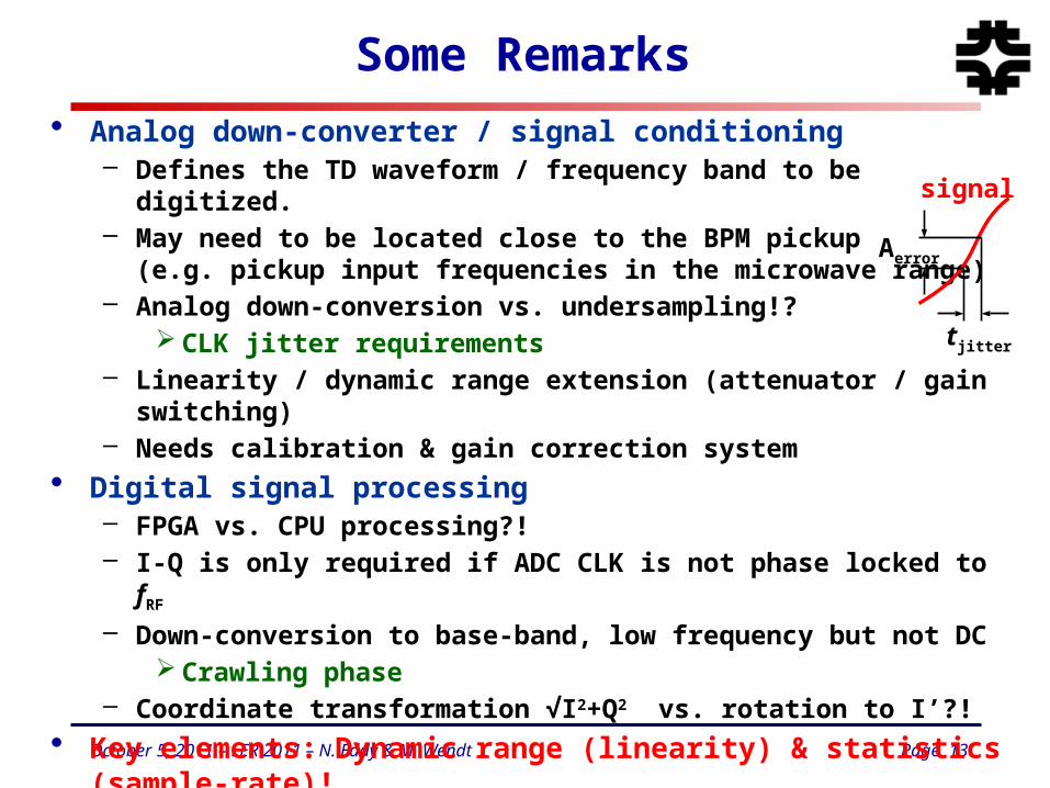
Some Remarks
• Analog down-converter / signal conditioning– Defines the TD waveform / frequency band to be digitized.– May need to be located close to the BPM pickup
(e.g. pickup input frequencies in the microwave range)– Analog down-conversion vs. undersampling!?
CLK jitter requirements– Linearity / dynamic range extension (attenuator / gain switching)– Needs calibration & gain correction system
• Digital signal processing– FPGA vs. CPU processing?!– I-Q is only required if ADC CLK is not phase locked to fRF
– Down-conversion to base-band, low frequency but not DC Crawling phase
– Coordinate transformation √I2+Q2 vs. rotation to I’?!
• Key elements: Dynamic range (linearity) & statistics (sample-rate)!• Practical considerations, e.g. cabling, VME, xTCA, pizza-box, etc.
tjitter
Aerror
signal
Page 14October 5, 2011 – LER 2011 – N. Eddy & M. Wendt
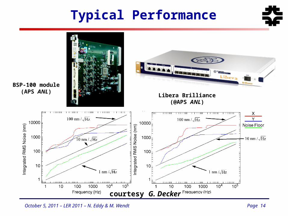
Typical Performance
BSP-100 module(APS ANL)
Libera Brilliance(@APS ANL)
courtesy G. Decker
Page 15October 5, 2011 – LER 2011 – N. Eddy & M. Wendt
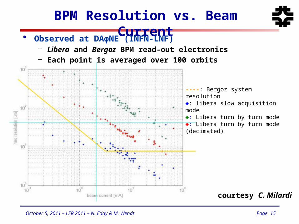
BPM Resolution vs. Beam Current
----: Bergoz system resolution: libera slow acquisition mode: Libera turn by turn mode: Libera turn by turn mode (decimated)
courtesy C. Milardi
• Observed at DAϕNE (INFN-LNF)– Libera and Bergoz BPM read-out electronics– Each point is averaged over 100 orbits
Page 16October 5, 2011 – LER 2011 – N. Eddy & M. Wendt
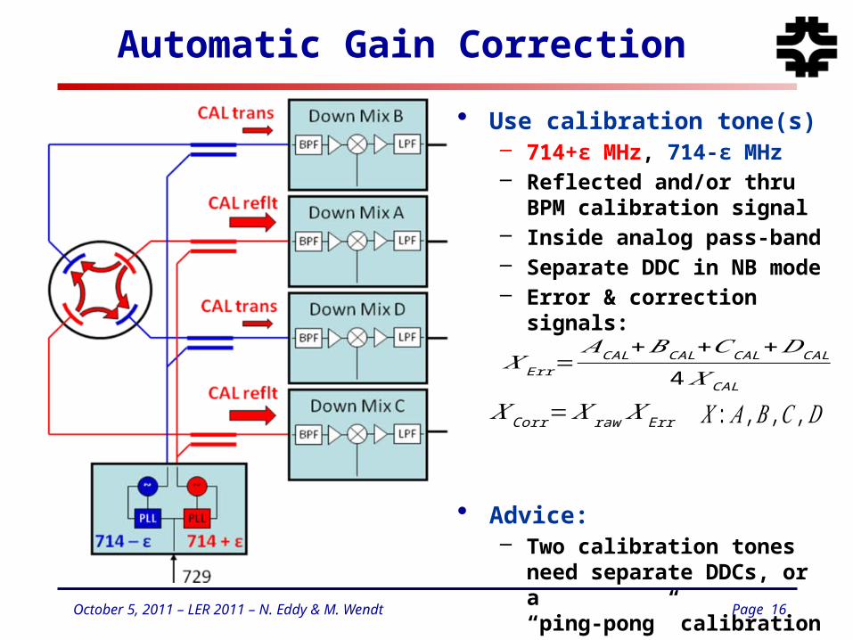
Automatic Gain Correction
• Use calibration tone(s)– 714+ε MHz, 714-ε MHz– Reflected and/or thru BPM
calibration signal– Inside analog pass-band– Separate DDC in NB mode– Error & correction signals:
• Advice:– Two calibration tones need
separate DDCs, or a“ping-pong” calibration tone workaround
𝑋Err=𝐴CAL+𝐵CAL+𝐶CAL+𝐷CAL
4 𝑋CAL
𝑋Corr=𝑋 raw 𝑋 Err 𝑋 : 𝐴 ,𝐵 ,𝐶 ,𝐷
Page 17October 5, 2011 – LER 2011 – N. Eddy & M. Wendt
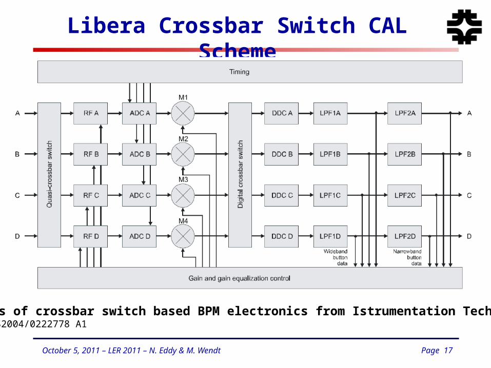
Libera Crossbar Switch CAL Scheme
Schematics of crossbar switch based BPM electronics from Istrumentation Technologies.Pat. No.: US2004/0222778 A1
Page 18October 5, 2011 – LER 2011 – N. Eddy & M. Wendt
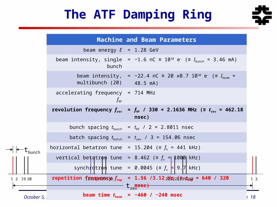
The ATF Damping Ring
Machine and Beam Parameters
beam energy E = 1.28 GeV
beam intensity, single bunch ≈ ~1.6 nC ≡ 1010 e- (≡ Ibunch ≈ 3.46 mA)
beam intensity, multibunch (20) ≈ ~22.4 nC ≡ 20 x0.7 1010 e- (≡ Ibeam ≈ 48.5 mA)
accelerating frequency fRF = 714 MHz
revolution frequency frev = fRF / 330 = 2.1636 MHz (≡ trev = 462.18 nsec)
bunch spacing tbunch = tRF / 2 = 2.8011 nsec
batch spacing tbatch = trev / 3 = 154.06 nsec
horizontal betatron tune ≈ 15.204 (≡ fh ≈ 441 kHz)
vertical betatron tune ≈ 8.462 (≡ fv ≈ 1000 kHz)
synchrotron tune ≈ 0.0045 (≡ fs ≈ 9.7 kHz)
repetition frequency frep = 1.56 /3.12 Hz (≡ trep = 640 / 320 msec)
beam time tbeam = ~460 / ~240 msec
1 2 19 20 1 2111 112 129 130 221 222 239 240
trev
tbunch
Page 19October 5, 2011 – LER 2011 – N. Eddy & M. Wendt
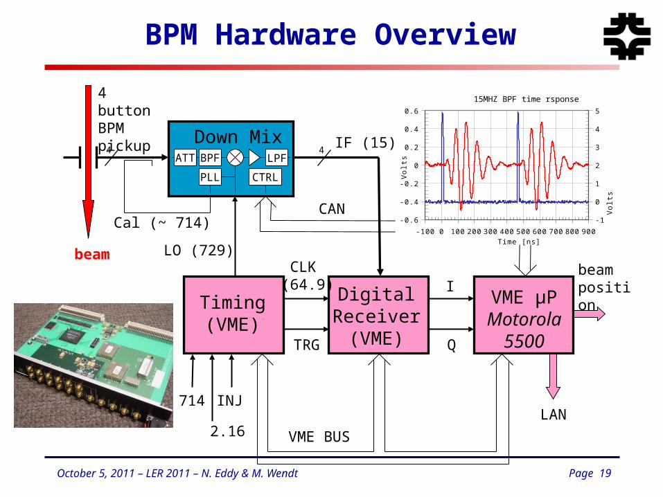
BPM Hardware Overview
BPF LPF
714
2.16
INJ
Down Mix
Cal (~ 714)
Timing(VME)
LO (729)CLK (64.9)
TRG
Digital Receiver
(VME)
VME µPMotorola
5500Q
Ibeamposition
4 buttonBPMpickup
IF (15)
beam
VME BUS
LAN
PLL
4ATT
4
CAN
CTRL
-100 0 100 200 300 400 500 600 700 800 900
-0.6
-0.4
-0.2
0
0.2
0.4
0.6
-1
0
1
2
3
4
5
15MHZ BPF time rsponse
Time [ns]
Vo
lts
Vo
lts
Page 20October 5, 2011 – LER 2011 – N. Eddy & M. Wendt
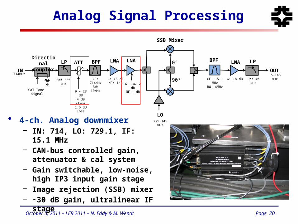
Analog Signal Processing
• 4-ch. Analog downmixer– IN: 714, LO: 729.1, IF: 15.1 MHz– CAN-bus controlled gain,
attenuator & cal system– Gain switchable, low-noise, high
IP3 input gain stage– Image rejection (SSB) mixer– ~30 dB gain, ultralinear IF stage
15.145 MHz
BPFATT LNA BPF LNA LPF
SSB Mixer
LO
0°
90°
LNALPFDirectional
CouplerIN
714MHzCF: 714MHzBW: 10MHz G: 14/-2 dB
NF: 1dB0 - 28 dB
4 dB steps1.6 dB loss
729.145 MHz
CF: 15.1 MHzBW: 4MHz
G: 18 dB BW: 40 MHz
OUT
BW: 800 MHz G: 15 dBNF: 1dB
Cal Tone Signal
Page 21October 5, 2011 – LER 2011 – N. Eddy & M. Wendt
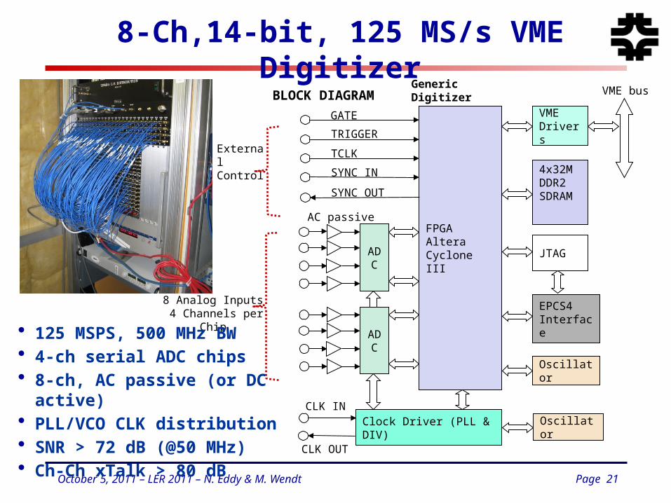
8-Ch,14-bit, 125 MS/s VME Digitizer
BLOCK DIAGRAM
FPGAAlteraCyclone III
VMEDrivers
4x32MDDR2SDRAM
JTAG
EPCS4Interface
VME bus
Oscillator
Oscillator
CLK IN
CLK OUT
GATE
TRIGGER
TCLK
SYNC IN
SYNC OUT
Generic Digitizer
External Control
Clock Driver (PLL & DIV)
ADC
ADC
AC passive
8 Analog Inputs 4 Channels per Chip
• 125 MSPS, 500 MHz BW• 4-ch serial ADC chips• 8-ch, AC passive (or DC active)• PLL/VCO CLK distribution• SNR > 72 dB (@50 MHz)• Ch-Ch xTalk > 80 dB
Page 22October 5, 2011 – LER 2011 – N. Eddy & M. Wendt
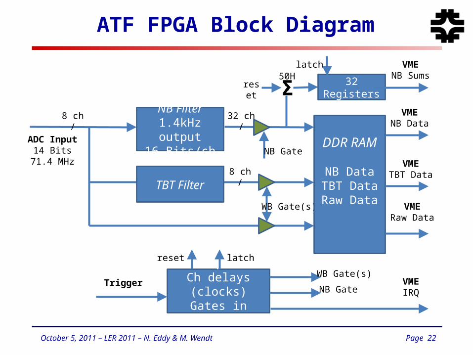
ATF FPGA Block Diagram
ADC Input14 Bits
71.4 MHz
NB Filter1.4kHz output
16 Bits/ch
32 ch/
NB Gate
WB Gate(s)
DDR RAM
NB DataTBT DataRaw Data
Σ50Hz
VMENB Data
VMERaw Data
TBT Filter
VMETBT Data
8 ch/
Trigger DAQ SMCh delays (clocks)
Gates in Turns
WB Gate(s)
NB Gate
32 Registers
VMENB Sums
VMEIRQ
reset latch
reset
latch
8 ch/
Page 23October 5, 2011 – LER 2011 – N. Eddy & M. Wendt
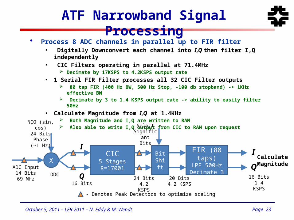
ATF Narrowband Signal Processing
• Process 8 ADC channels in parallel up to FIR filter• Digitally Downconvert each channel into I,Q then filter I,Q independently• CIC Filters operating in parallel at 71.4MHz
Decimate by 17KSPS to 4.2KSPS output rate
• 1 Serial FIR Filter processes all 32 CIC Filter outputs 80 tap FIR (400 Hz BW, 500 Hz Stop, -100 db stopband) -> 1KHz effective BW Decimate by 3 to 1.4 KSPS output rate -> ability to easily filter 50Hz
• Calculate Magnitude from I,Q at 1.4KHz Both Magnitude and I,Q are written to RAM Also able to write I,Q output from CIC to RAM upon request
ADC Input14 Bits69 MHz
X
NCO (sin, cos)24 Bits Phase
(~1 Hz)
I
Q16 Bits
CIC5 StagesR=17001
DDC24 Bits
4.2 KSPS
FIR (80 taps)LPF 500HzDecimate 3
BitShift
SelectSignificant
Bits
20 Bits4.2 KSPS
16 Bits1.4 KSPS
I
Q
- Denotes Peak Detectors to optimize scaling
CalculateMagnitude
Page 24October 5, 2011 – LER 2011 – N. Eddy & M. Wendt
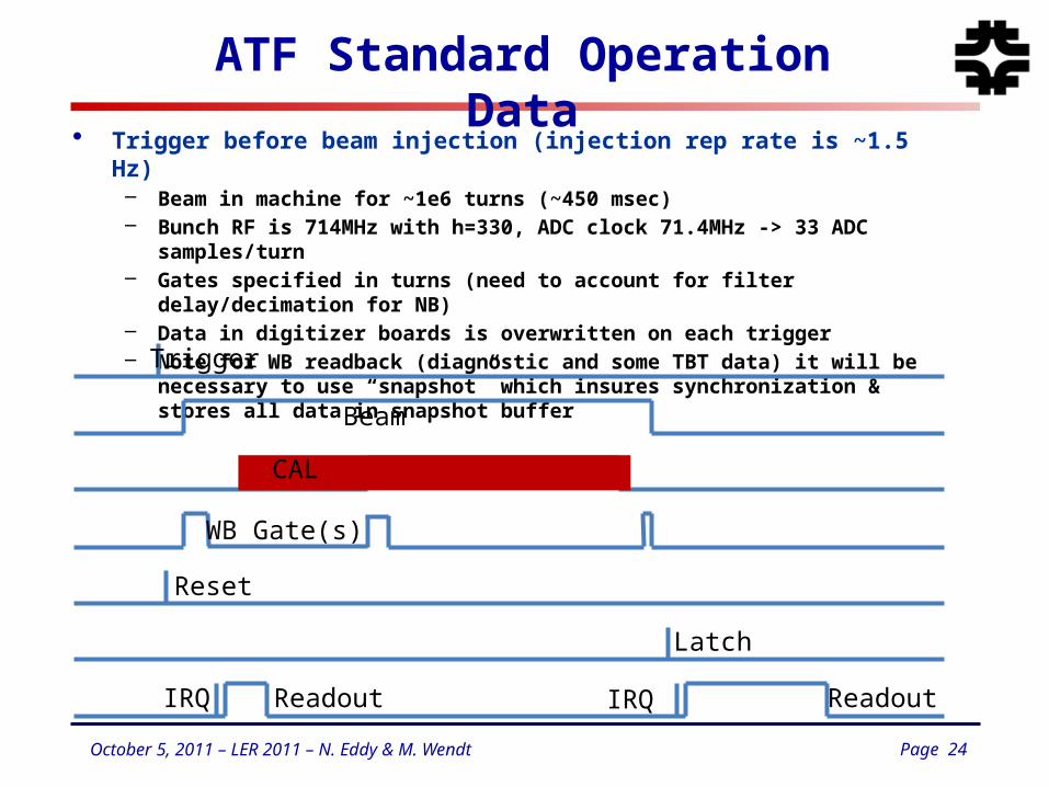
ATF Standard Operation Data
• Trigger before beam injection (injection rep rate is ~1.5 Hz)– Beam in machine for ~1e6 turns (~450 msec)– Bunch RF is 714MHz with h=330, ADC clock 71.4MHz -> 33 ADC samples/turn– Gates specified in turns (need to account for filter delay/decimation for NB)– Data in digitizer boards is overwritten on each trigger– Note for WB readback (diagnostic and some TBT data) it will be necessary to use
“snapshot” which insures synchronization & stores all data in snapshot buffer
Trigger
Beam
NB Gate
WB Gate(s)
Reset
Latch
IRQ ReadoutReadoutIRQ
CAL
Page 25October 5, 2011 – LER 2011 – N. Eddy & M. Wendt
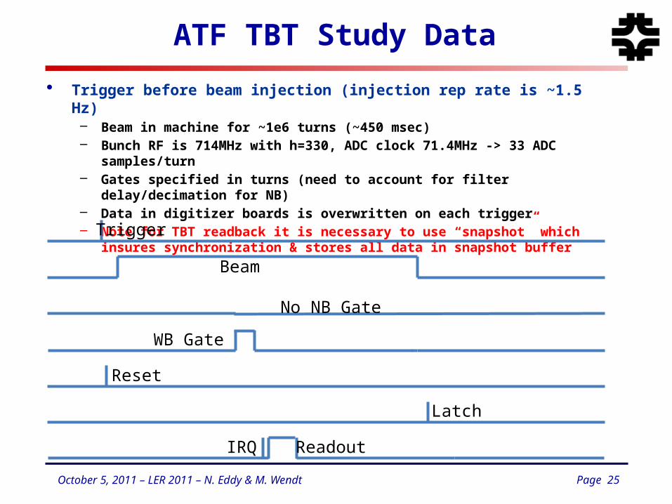
ATF TBT Study Data
• Trigger before beam injection (injection rep rate is ~1.5 Hz)– Beam in machine for ~1e6 turns (~450 msec)– Bunch RF is 714MHz with h=330, ADC clock 71.4MHz -> 33 ADC samples/turn– Gates specified in turns (need to account for filter delay/decimation for NB)– Data in digitizer boards is overwritten on each trigger– Note for TBT readback it is necessary to use “snapshot” which insures
synchronization & stores all data in snapshot buffer
Trigger
Beam
No NB Gate
WB Gate
Reset
Latch
ReadoutIRQ
Page 26October 5, 2011 – LER 2011 – N. Eddy & M. Wendt
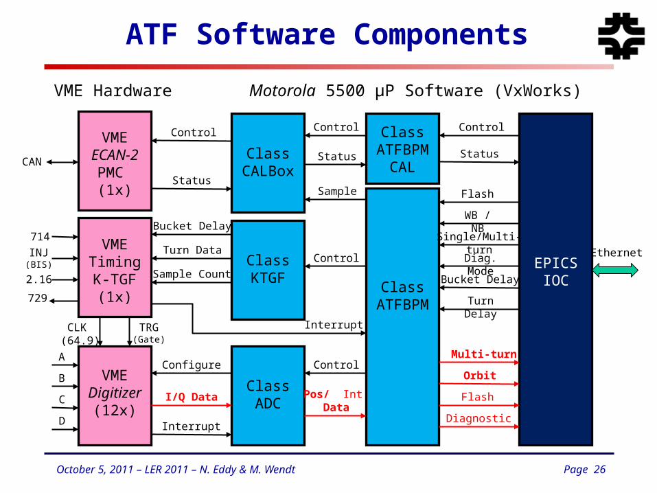
ATF Software Components
VMEECAN-2
PMC (1x)
VMETimingK-TGF
(1x)
VMEDigitizer
(12x)
CLK (64.9)
TRG(Gate)
A
B
C
D
714
2.16
INJ(BIS)
729
CAN
ClassADC
Interrupt
I/Q Data
Configure
ClassKTGF
Bucket Delay
Turn Data
Sample Count
ClassCALBox
Control
Status
ClassATFBPM
ClassATFBPM
CAL
Control
Status
Sample
Control
Interrupt
Control
Pos/ Int Data
EPICSIOC
Control
Status
Flash
WB / NB
Single/Multi-turn
Diag. Mode
Bucket Delay
Turn Delay
Diagnostic
Flash
Orbit
Multi-turn
VME Hardware Motorola 5500 µP Software (VxWorks)
Ethernet
Page 27October 5, 2011 – LER 2011 – N. Eddy & M. Wendt
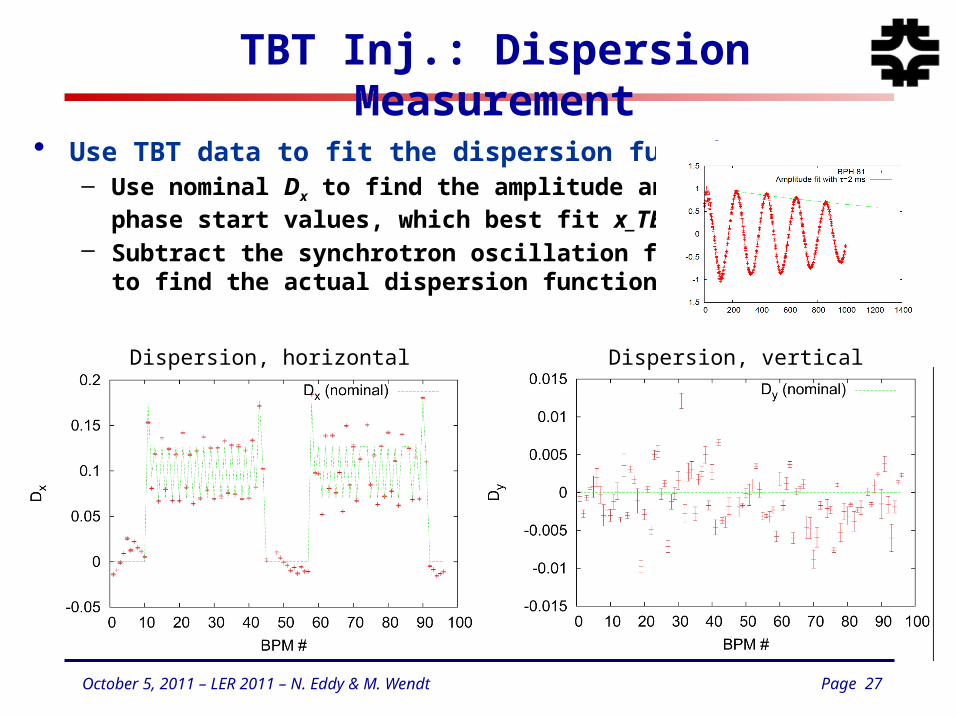
TBT Inj.: Dispersion Measurement
Dispersion, horizontal Dispersion, vertical
• Use TBT data to fit the dispersion functions– Use nominal Dx to find the amplitude and
phase start values, which best fit x_TBT.– Subtract the synchrotron oscillation from x_TBT,
to find the actual dispersion function.
Page 28October 5, 2011 – LER 2011 – N. Eddy & M. Wendt
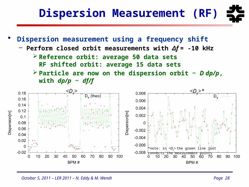
Dispersion Measurement (RF)
• Dispersion measurement using a frequency shift– Perform closed orbit measurements with Δf = -10 kHz
Reference orbit: average 50 data setsRF shifted orbit: average 15 data sets
Particle are now on the dispersion orbit ~ D dp/p, with dp/p ~ df/f
<Dx> <Dy>*
*note: in <Dy> the green line justconnects the measurement points
Page 29October 5, 2011 – LER 2011 – N. Eddy & M. Wendt
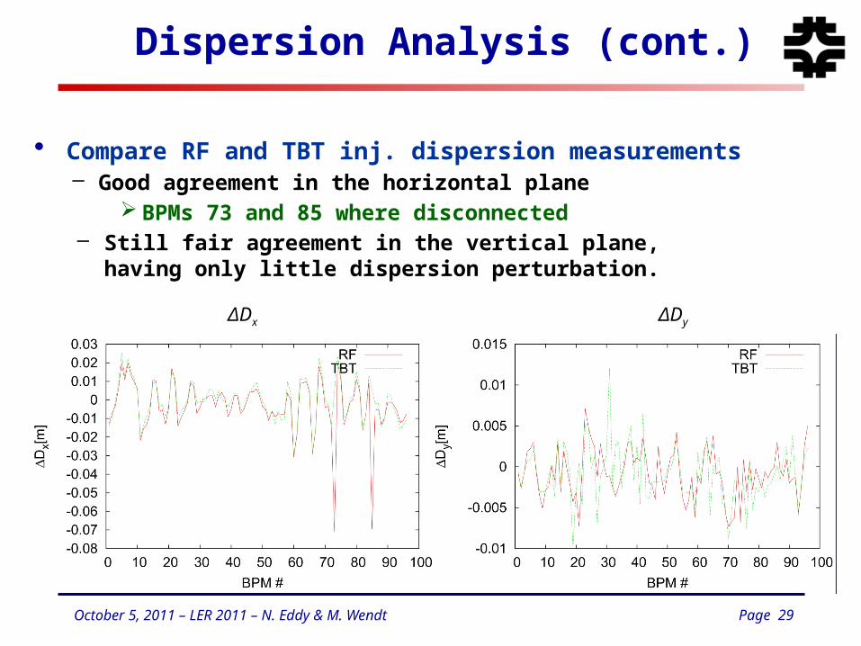
Dispersion Analysis (cont.)
• Compare RF and TBT inj. dispersion measurements– Good agreement in the horizontal plane
BPMs 73 and 85 where disconnected– Still fair agreement in the vertical plane,
having only little dispersion perturbation.
ΔDx ΔDy
Page 30October 5, 2011 – LER 2011 – N. Eddy & M. Wendt
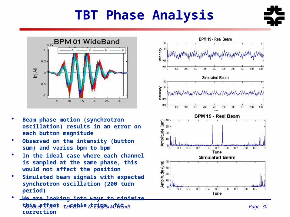
TBT Phase Analysis
• Beam phase motion (synchrotron oscillation) results in an error on each button magnitude
• Observed on the intensity (button sum) and varies bpm to bpm
• In the ideal case where each channel is sampled at the same phase, this would not affect the position
• Simulated beam signals with expected synchrotron oscillation (200 turn period)
• We are looking into ways to minimize this effect – cable trims, fit correction
Page 31October 5, 2011 – LER 2011 – N. Eddy & M. Wendt
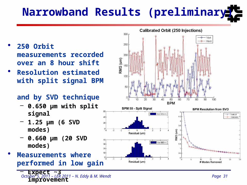
Narrowband Results (preliminary)
• 250 Orbit measurements recorded over an 8 hour shift
• Resolution estimated with split signal BPM and by SVD technique– 0.650 μm with split signal– 1.25 μm (6 SVD modes)– 0.660 μm (20 SVD modes)
• Measurements where performed in low gain– Expect ~3 improvement
• Need more investigations!
Page 32October 5, 2011 – LER 2011 – N. Eddy & M. Wendt
Summary & Final Remarks
• Trend to digital signal processing, plus some analog electronics with integrated calibration / drift correction scheme.– Complex processing / math in the digital domain.– Very flexible by FPGA re-programming, however labor intensive!
• ATF BPM system has been implemented using this scheme– Custom analog downmix module
Tailored to machine parameters Integrated gain control and calibration
– Custom digitizer ADC locked to machine RF Can customize signal processing to specific needs
– CO, TBT, FFT, etc– EPICs software interface
• ATF Installation complete at the end of 2010– Initial commissioning successful– Beam studies to continue – BBA, Tilt -> low emmittance operation!