MAX9709 25W/50W, Filterless, Spread-Spectrum, Stereo/Mono ...
TLT-5606 Spread Spectrum TechniquesChapter 2: Pseudorandom sequences
Toni HuovinenTampere University of Technology
Slides are mainly based on the original lecture notes by prof. Tapani Ristaniemi.
Basic synchronous CDMA model
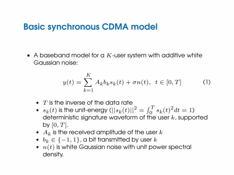
n A baseband model for a K-user system with additive whiteGaussian noise:
y(t) =
K∑
k=1
Akbksk(t) + σn(t), t ∈ [0, T ] (1)
l T is the inverse of the data ratel sk(t) is the unit-energy (||sk(t)||2 =
∫ T0 sk(t)2dt = 1)
deterministic signature waveform of the user k, supportedby [0, T ].
l Ak is the received amplitude of the user kl bk ∈ {−1, 1}, a bit transmitted by user kl n(t) is white Gaussian noise with unit power spectral
density.
n The performance of demodulation of a particular userdepends (given that the phase of the signature sequence isknown at the receiver) mainly on the signal-to-noise ratio(SNR) of a particular user, Ak/σ, and degree of similaritybetween the signature waveforms.
n Similarity measure: crosscorrelation ρkl:
ρkl =< sk, sl >=
∫ T
0sk(t)sl(t)dt (2)
n Properties:l ρkk = 1 for any kl ρkl ≤ 1
Basic asynchronous CDMA model
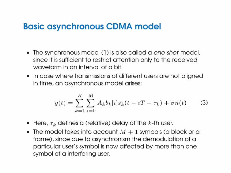
n The synchronous model (1) is also called a one-shot model,since it is sufficient to restrict attention only to the receivedwaveform in an interval of a bit.
n In case where transmissions of different users are not alignedin time, an asynchronous model arises:
y(t) =
K∑
k=1
M∑
i=0
Akbk[i]sk(t− iT − τk) + σn(t) (3)
n Here, τk defines a (relative) delay of the k-th user.n The model takes into account M + 1 symbols (a block or a
frame), since due to asynchronism the demodulation of aparticular user’s symbol is now affected by more than onesymbol of a interfering user.
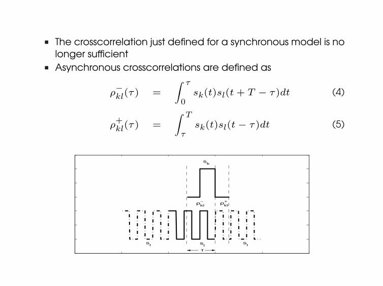
n The crosscorrelation just defined for a synchronous model is nolonger sufficient
n Asynchronous crosscorrelations are defined as
ρ−kl(τ) =
∫ τ
0sk(t)sl(t + T − τ)dt (4)
ρ+kl(τ) =
∫ T
τsk(t)sl(t− τ)dt (5)
sk
sl s
ls
l
τ
ρkl+ ρ
kl−
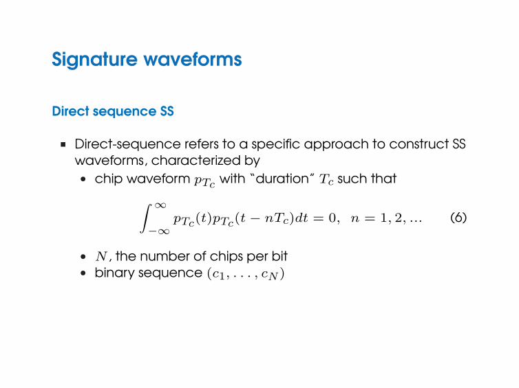
Signature waveforms
Direct sequence SS
n Direct-sequence refers to a specific approach to construct SSwaveforms, characterized by
l chip waveform pTc with “duration” Tc such that
∫ ∞
−∞pTc(t)pTc(t− nTc)dt = 0, n = 1, 2, ... (6)
l N , the number of chips per bitl binary sequence (c1, . . . , cN)
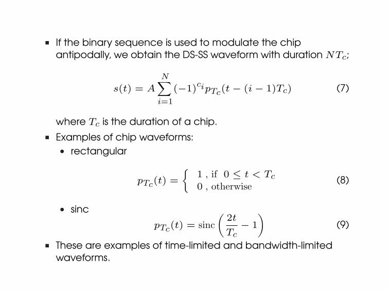
n If the binary sequence is used to modulate the chipantipodally, we obtain the DS-SS waveform with duration NTc;
s(t) = A
N∑
i=1
(−1)cipTc(t− (i− 1)Tc) (7)
where Tc is the duration of a chip.n Examples of chip waveforms:
l rectangular
pTc(t) =
{1 , if 0 ≤ t < Tc
0 , otherwise(8)
l sinc
pTc(t) = sinc(
2t
Tc− 1
)(9)
n These are examples of time-limited and bandwidth-limitedwaveforms.
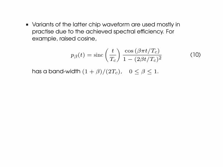
n Variants of the latter chip waveform are used mostly inpractise due to the achieved spectral efficiency. Forexample, raised cosine,
pβ(t) = sinc(
t
Tc
)cos (βπt/Tc)
1− (2βt/Tc)2(10)
has a band-width (1 + β)/(2Tc), 0 ≤ β ≤ 1.
Spreading factor
The number of chips N per bit is also called spreading factor or aprocessing gain, and it has the following properties:
n Bandwidth of the DS-SS signal is proportional to N (for a fixedduration of the signature waveform)
n For a given signal-to-noise ratio (A/σ), the single-userbit-error-rate in a white Gaussian noise is independent of N
n If N is a power of 2, an orthogonal synchronous CDMA systemcan support N users
n Large values on N contribute to the privacy of the system, asit makes eavesdropping more difficult
n Large values contribute to reduce the interference causedon/by a co-existing narrowband transmission (cf. CDMAoverlay)
n The reliability for chip timing determination increases with N
Signature sequences
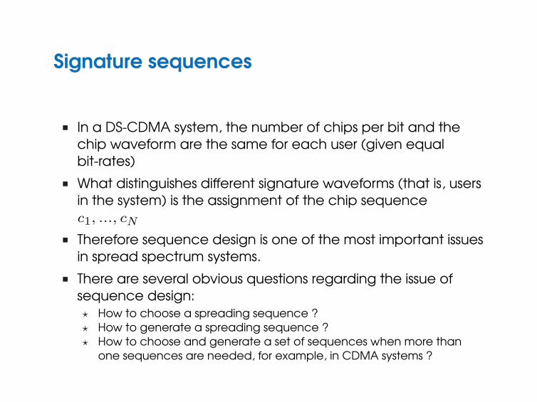
n In a DS-CDMA system, the number of chips per bit and thechip waveform are the same for each user (given equalbit-rates)
n What distinguishes different signature waveforms (that is, usersin the system) is the assignment of the chip sequencec1, ..., cN
n Therefore sequence design is one of the most important issuesin spread spectrum systems.
n There are several obvious questions regarding the issue ofsequence design:? How to choose a spreading sequence ?? How to generate a spreading sequence ?? How to choose and generate a set of sequences when more than
one sequences are needed, for example, in CDMA systems ?
n The questions are not independent. For example, practicalconstraint on sequence generation may limit the set ofsequence we can choose from.
n To start with, let’s first list the most imporant properties wewant the spreading sequences to possess:? The elements of a chip sequence should behave like i.i.d.
random variables, i.e., the sequence should bepseudo-random.
? It should be easy to distinguish a spreading signal from atime-shifted version of it
? A chip sequence should be easy to distinguish from othersequences, including time-shifted versions of them.
? It should be easy for the transmitter and the intendedreceiver to generate chip sequence.
? It should be difficult for any unintended receiver to acquireand regenerate the chip sequence.
Shift register
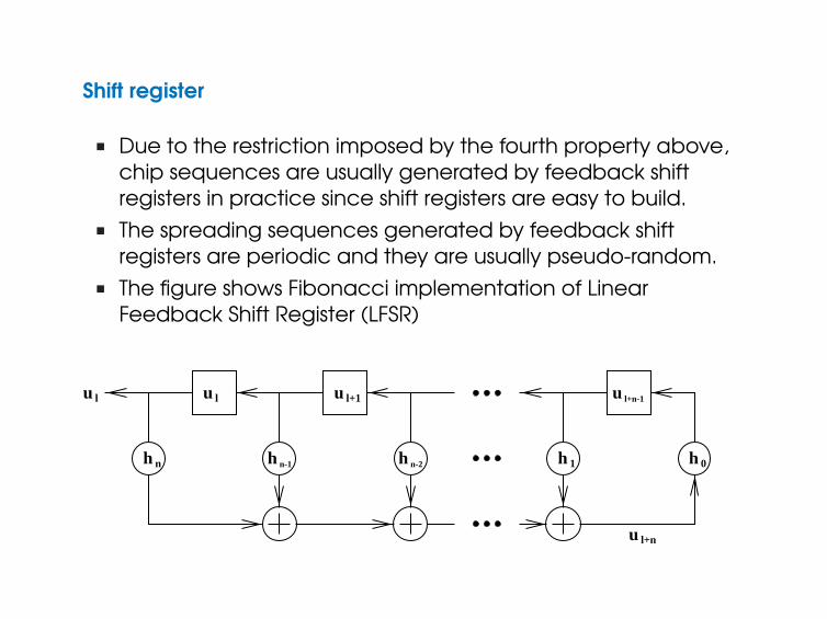
n Due to the restriction imposed by the fourth property above,chip sequences are usually generated by feedback shiftregisters in practice since shift registers are easy to build.
n The spreading sequences generated by feedback shiftregisters are periodic and they are usually pseudo-random.
n The figure shows Fibonacci implementation of LinearFeedback Shift Register (LFSR)
h n n-1h
u l+n-1u l+1u lu l
h h 01n-2h
u l+n
ul+n = hnul � hn�1ul+1 � : : :� h1ul+n�1;
� 2
h0; h1; : : : ; hn
h(x) = h0xn + h1x
n�1 + : : :+ hn�1x+ hn:
u h(x)
h(x) x4+x+1
h23ih(x)
0
h(x)
2n � 1
n ’⊕’ represents modulo-2 addition (XOR gate), and hi’s takevalues either 1 or 0. (connection / no connection).
n Hence, the output of the shift register is
ul+n = hnul ⊕ hn−1ul+1 ⊕ · · · ⊕ h1ul+n−1 (11)
n In fact, we always choose h0 = hn = 1. If h0 = 0, the outputvalues of the register would be all 0 after n shifts. On the otherhand, if hn = 0 we could remove the first storage elementwithout chancing the output sequence.
n ’¤’ represents a single binary storage element, resulting inmaximum of 2n different states for a shift register.
n Therefore, the output is periodic, with a period determined bythe tap values (hi’s) and initial fill of the storage elements.
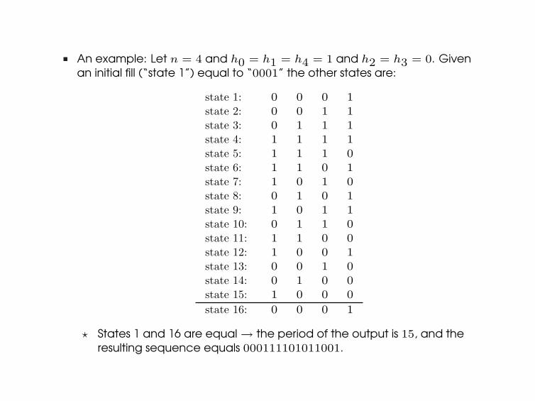
n An example: Let n = 4 and h0 = h1 = h4 = 1 and h2 = h3 = 0. Givenan initial fill (“state 1”) equal to “0001” the other states are:
state 1: 0 0 0 1state 2: 0 0 1 1state 3: 0 1 1 1state 4: 1 1 1 1state 5: 1 1 1 0state 6: 1 1 0 1state 7: 1 0 1 0state 8: 0 1 0 1state 9: 1 0 1 1state 10: 0 1 1 0state 11: 1 1 0 0state 12: 1 0 0 1state 13: 0 0 1 0state 14: 0 1 0 0state 15: 1 0 0 0
state 16: 0 0 0 1
? States 1 and 16 are equal → the period of the output is 15, and theresulting sequence equals 000111101011001.
Polynomial representations of LFSRs andsequences
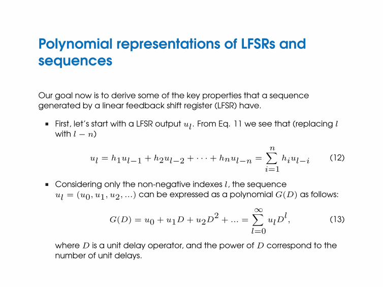
Our goal now is to derive some of the key properties that a sequencegenerated by a linear feedback shift register (LFSR) have.
n First, let’s start with a LFSR output ul. From Eq. 11 we see that (replacing lwith l− n)
ul = h1ul−1 + h2ul−2 + · · ·+ hnul−n =n∑
i=1
hiul−i (12)
n Considering only the non-negative indexes l, the sequenceul = (u0, u1, u2, ...) can be expressed as a polynomial G(D) as follows:
G(D) = u0 + u1D + u2D2
+ ... =∞∑
l=0
ulDl, (13)
where D is a unit delay operator, and the power of D correspond to thenumber of unit delays.
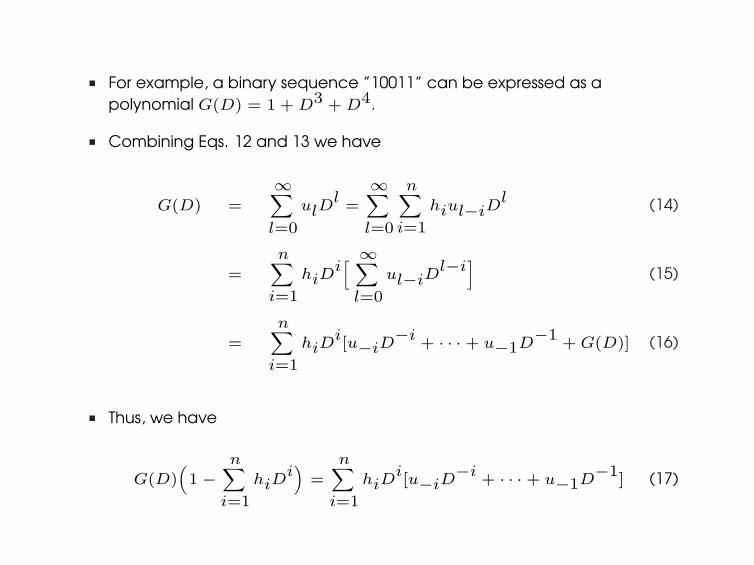
n For example, a binary sequence ”10011” can be expressed as apolynomial G(D) = 1 + D3 + D4.
n Combining Eqs. 12 and 13 we have
G(D) =∞∑
l=0
ulDl=∞∑
l=0
n∑
i=1
hiul−iDl (14)
=
n∑
i=1
hiDi[ ∞∑
l=0
ul−iDl−i
](15)
=
n∑
i=1
hiDi[u−iD
−i+ · · ·+ u−1D
−1+ G(D)] (16)
n Thus, we have
G(D)(1−
n∑
i=1
hiDi)
=
n∑
i=1
hiDi[u−iD
−i+ · · ·+ u−1D
−1] (17)
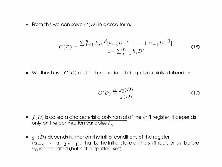
n From this we can solve G(D) in closed form:
G(D) =
∑ni=1 hiD
i[u−iD−i + · · ·+ u−1D−1]
1−∑ni=1 hiD
i(18)
n We thus have G(D) defined as a ratio of finite polynomials, defined as
G(D)∆=
g0(D)
f(D)(19)
n f(D) is called a characteristic polynomial of the shift register; it dependsonly on the connection variables hi.
n g0(D) depends further on the initial conditions of the register(u−n · · · u−2 u−1). That is, the initial state of the shift register just beforeu0 is generated (but not outputted yet).
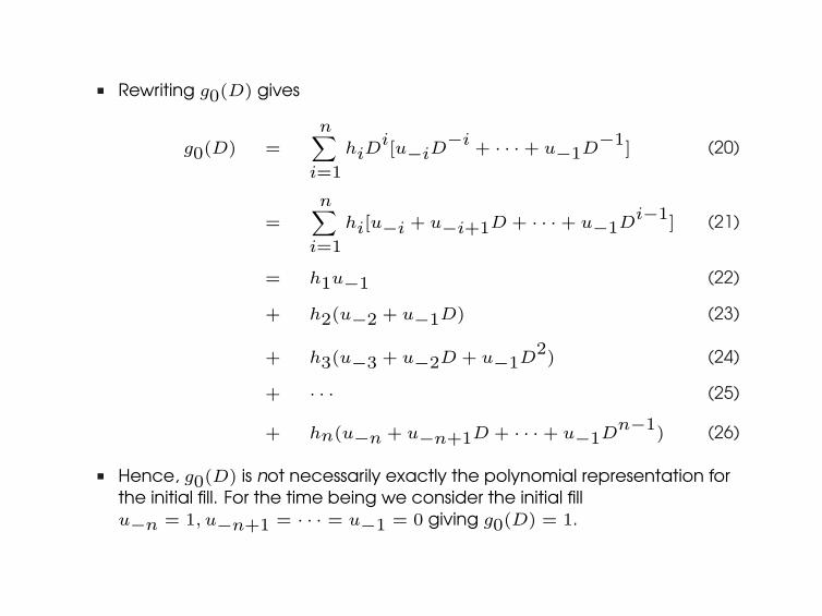
n Rewriting g0(D) gives
g0(D) =n∑
i=1
hiDi[u−iD
−i+ · · ·+ u−1D
−1] (20)
=n∑
i=1
hi[u−i + u−i+1D + · · ·+ u−1Di−1
] (21)
= h1u−1 (22)
+ h2(u−2 + u−1D) (23)
+ h3(u−3 + u−2D + u−1D2) (24)
+ · · · (25)
+ hn(u−n + u−n+1D + · · ·+ u−1Dn−1
) (26)
n Hence, g0(D) is not necessarily exactly the polynomial representation forthe initial fill. For the time being we consider the initial fillu−n = 1, u−n+1 = · · · = u−1 = 0 giving g0(D) = 1.
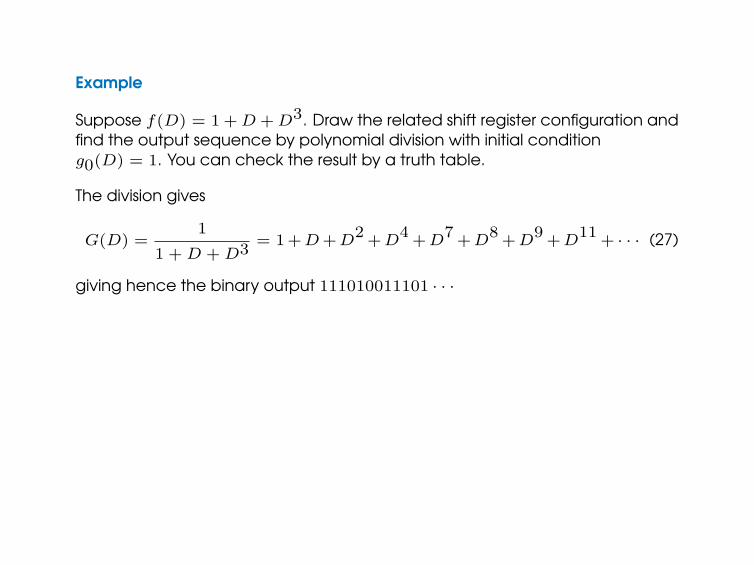
Example
Suppose f(D) = 1 + D + D3. Draw the related shift register configuration andfind the output sequence by polynomial division with initial conditiong0(D) = 1. You can check the result by a truth table.
The division gives
G(D) =1
1 + D + D3= 1+D +D
2+D
4+D
7+D
8+D
9+D
11+ · · · (27)
giving hence the binary output 111010011101 · · ·
Maximal length LFSR sequences
n What is the maximum period of the output ?n Recall that the output of the shift register is the sequence of successive
values for the storage element ul.n Thus, to have a maximum period for the output, the shift register of n
storage elements have to experience all the possible binarycombinations, that is, 2n of them.
n Disregarding the undesired state of the shift register (’all zeros’ resulting inan ’all zeros’ output for the register), the periodicity of the register is upperbounded by 2n − 1.
n Sequences that achieve that bound are called maximal-lengthsequences, or shortly m-sequences.
n Polynomial f(D) which generates an m-sequence, i.e., characteristicpolynomial of an m-sequence, is called primitive.
Properties of m-sequences
Property A: A maximal length sequence contains one more ”1” than ”0”.
n This is also called a ”Balanced property”: there are exactly 2n−1 onesand 2n−1 − 1 zeros.
n This is because from all the possible 2n − 1 states of a shift register plus the”all zeros” state, exactly one half of them begin with 0 and the other halfbegin with 1. Thus, excluding the forbidden state, we have the Property A.
Notice, that if we map the binary values ul into the values ±1 according tocl = (−1)ul , then the Property A equals the following temporal property:
1
N
N∑
i=1
ci = − 1
N(28)
Thus, the imbalance from a zero-mean variable is N−1, which for n = 10, 30,
and 50 is approximately 10−3, 10−9, and 10−15, respectively.
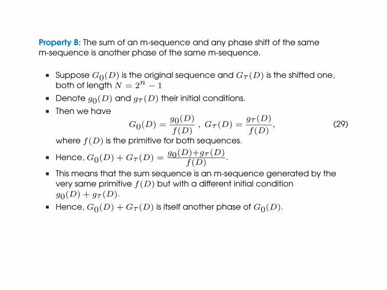
Property B: The sum of an m-sequence and any phase shift of the samem-sequence is another phase of the same m-sequence.
n Suppose G0(D) is the original sequence and Gτ (D) is the shifted one,both of length N = 2n − 1
n Denote g0(D) and gτ (D) their initial conditions.n Then we have
G0(D) =g0(D)
f(D), Gτ (D) =
gτ (D)
f(D), (29)
where f(D) is the primitive for both sequences.
n Hence, G0(D) + Gτ (D) =g0(D)+gτ (D)
f(D).
n This means that the sum sequence is an m-sequence generated by thevery same primitive f(D) but with a different initial conditiong0(D) + gτ (D).
n Hence, G0(D) + Gτ (D) is itself another phase of G0(D).
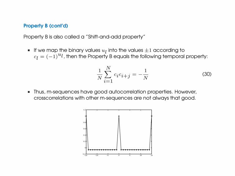
Property B (cont’d)
Property B is also called a ”Shift-and-add property”
n If we map the binary values ul into the values ±1 according tocl = (−1)ul , then the Property B equals the following temporal property:
1
N
N∑
i=1
cici+j = − 1
N(30)
n Thus, m-sequences have good autocorrelation properties. However,crosscorrelations with other m-sequences are not always that good.
−15 −10 −5 0 5 10 15−0.2
0
0.2
0.4
0.6
0.8
1
1.2
Security of m-sequence
n SS systems are used to protect digital transmission from being jammed. Thisis achieved if the jammer has no knowledge of the spreading waveform.
n Unfortunately, if the jammer receives a relatively noise-free copy of thetransmitted signal, the related shift register is pretty easy to bedetermined. For this reason, short m-sequences are a poor choice.
n How to find out the LFSR used by the transmitter ? Recall that m-sequencesatisfies Eq. 12:
ul = h1ul−1 + h2ul−2 + · · ·+ hnul−n =n∑
i=1
hiul−i (31)
n As soon as we have n such equations, hi’s can be easily found.
Security of m-sequence: example
Suppose a sequence ”00100110....” is received, and we have a knowledgethat the period is 15. Hence, n = 4 and we have a set of equations:
0 = h1 ∗ 1 + h2 ∗ 1 + h3 ∗ 0 + h4 ∗ 0 (32)
1 = h1 ∗ 1 + h2 ∗ 0 + h3 ∗ 0 + h4 ∗ 1 (33)
1 = h1 ∗ 0 + h2 ∗ 0 + h3 ∗ 1 + h4 ∗ 0 (34)
0 = h1 ∗ 0 + h2 ∗ 1 + h3 ∗ 0 + h4 ∗ 0 (35)
From Eq. 34 we have 1 = h3 ∗ 1 = h3, and from Eq. 35 we have0 = h2 ∗ 1 = h2. Substituting h2 = 0 and h3 = 1 to Eqs. 32 and 33 we haveh1 = 0 and h4 = 1.
Therefore, remembering that h0 = 1 always, we have f(D) = 1 + D3 + D4.
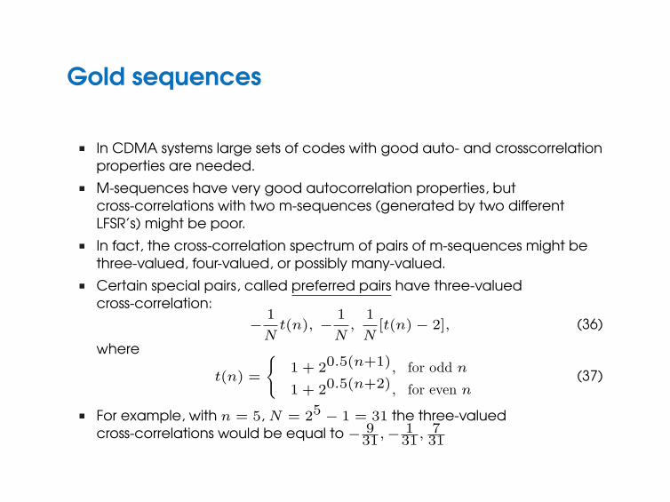
Gold sequences
n In CDMA systems large sets of codes with good auto- and crosscorrelationproperties are needed.
n M-sequences have very good autocorrelation properties, butcross-correlations with two m-sequences (generated by two differentLFSR’s) might be poor.
n In fact, the cross-correlation spectrum of pairs of m-sequences might bethree-valued, four-valued, or possibly many-valued.
n Certain special pairs, called preferred pairs have three-valuedcross-correlation:
− 1
Nt(n), − 1
N,
1
N[t(n)− 2], (36)
where
t(n) =
{1 + 20.5(n+1), for odd n
1 + 20.5(n+2), for even n(37)
n For example, with n = 5, N = 25 − 1 = 31 the three-valuedcross-correlations would be equal to − 9
31,− 131, 7
31
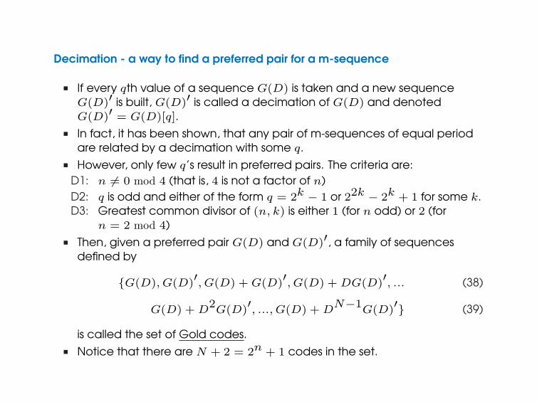
Decimation - a way to find a preferred pair for a m-sequence
n If every qth value of a sequence G(D) is taken and a new sequenceG(D)′ is built, G(D)′ is called a decimation of G(D) and denotedG(D)′ = G(D)[q].
n In fact, it has been shown, that any pair of m-sequences of equal periodare related by a decimation with some q.
n However, only few q’s result in preferred pairs. The criteria are:D1: n 6= 0 mod 4 (that is, 4 is not a factor of n)D2: q is odd and either of the form q = 2k − 1 or 22k − 2k + 1 for some k.D3: Greatest common divisor of (n, k) is either 1 (for n odd) or 2 (for
n = 2 mod 4)n Then, given a preferred pair G(D) and G(D)′, a family of sequences
defined by
{G(D), G(D)′, G(D) + G(D)
′, G(D) + DG(D)
′, ... (38)
G(D) + D2G(D)
′, ..., G(D) + D
N−1G(D)
′} (39)
is called the set of Gold codes.n Notice that there are N + 2 = 2n + 1 codes in the set.
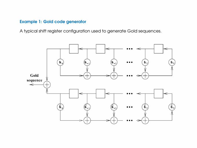
Example 1: Gold code generator
A typical shift register configuration used to generate Gold sequences.
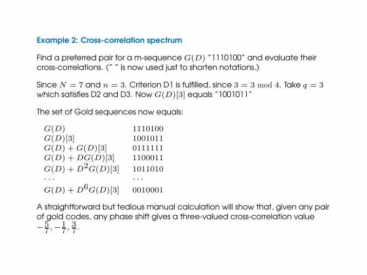
Example 2: Cross-correlation spectrum
Find a preferred pair for a m-sequence G(D) ”1110100” and evaluate theircross-correlations. (” ” is now used just to shorten notations.)
Since N = 7 and n = 3. Criterion D1 is fulfilled, since 3 = 3 mod 4. Take q = 3which satisfies D2 and D3. Now G(D)[3] equals ”1001011”
The set of Gold sequences now equals:
G(D) 1110100G(D)[3] 1001011G(D) + G(D)[3] 0111111G(D) + DG(D)[3] 1100011
G(D) + D2G(D)[3] 1011010· · · · · ·G(D) + D6G(D)[3] 0010001
A straightforward but tedious manual calculation will show that, given any pairof gold codes, any phase shift gives a three-valued cross-correlation value−5
7,−17, 3
7 .
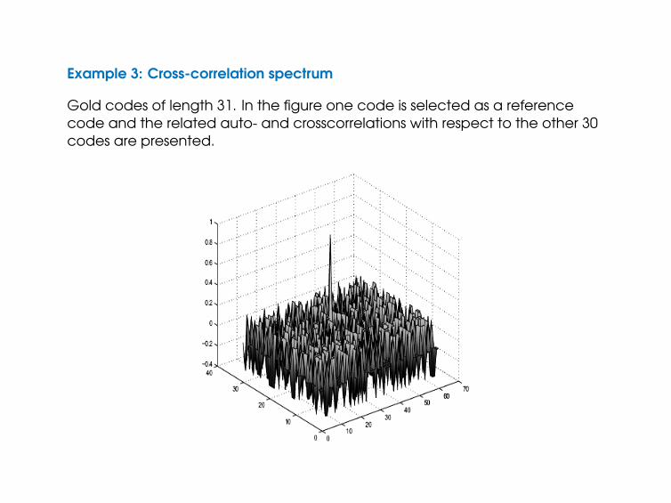
Example 3: Cross-correlation spectrum
Gold codes of length 31. In the figure one code is selected as a referencecode and the related auto- and crosscorrelations with respect to the other 30codes are presented.
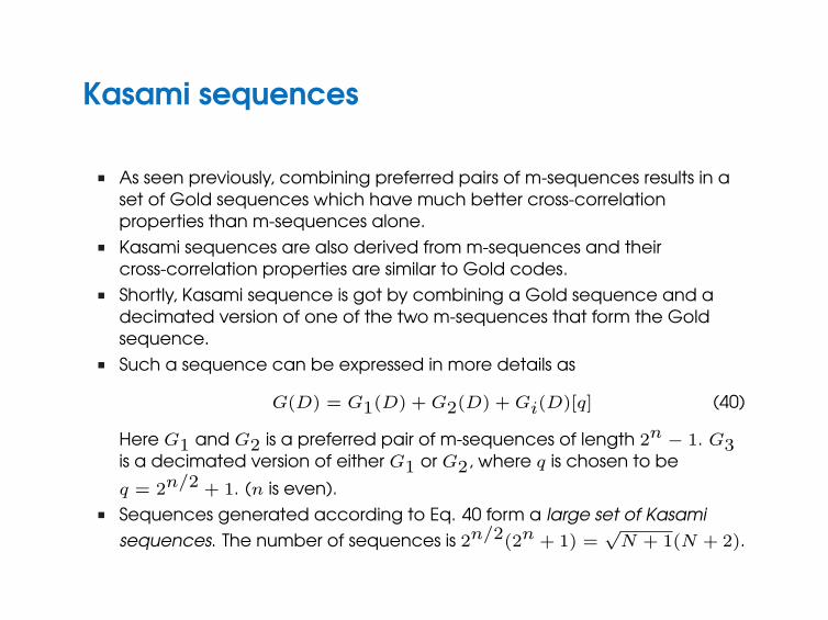
Kasami sequences
n As seen previously, combining preferred pairs of m-sequences results in aset of Gold sequences which have much better cross-correlationproperties than m-sequences alone.
n Kasami sequences are also derived from m-sequences and theircross-correlation properties are similar to Gold codes.
n Shortly, Kasami sequence is got by combining a Gold sequence and adecimated version of one of the two m-sequences that form the Goldsequence.
n Such a sequence can be expressed in more details as
G(D) = G1(D) + G2(D) + Gi(D)[q] (40)
Here G1 and G2 is a preferred pair of m-sequences of length 2n − 1. G3is a decimated version of either G1 or G2, where q is chosen to be
q = 2n/2 + 1. (n is even).n Sequences generated according to Eq. 40 form a large set of Kasami
sequences. The number of sequences is 2n/2(2n + 1) =√
N + 1(N + 2).
Orthogonal code sequences
n Gold and Kasami sequences have rather good cross-correlationproperties, which make them attractive in CDMA systems.
n So, are pure orthogonal codes of any use ?n Orthogonal codes usually have poor autocorrelation properties making
them useless in asynchronous access.n However, if the transmissions would be synchronous, the users are
completely transparent for each others given a single-path channel.n But now the existence of multi-paths would cause strong ISI/IPI ;(n To circumvent that, one solution to maintain orthogonality is
chip-equalization. This means that the channel is equalized into asingle-path channel prior to despreading, which thus restoresorthogonality between the users.
n Hence, orthogonal codes would be a sensible choice in downlink(base-to-mobile) communication provided that mobile units performchip-equalization.
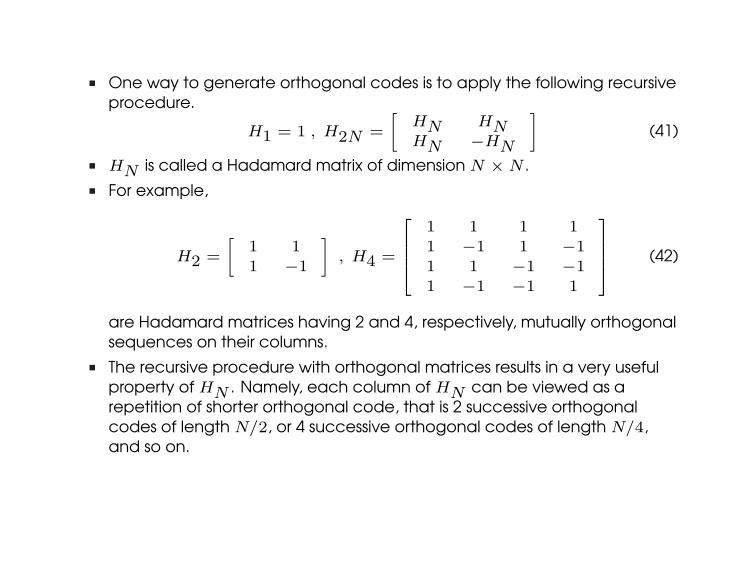
n One way to generate orthogonal codes is to apply the following recursiveprocedure.
H1 = 1 , H2N =
[HN HNHN −HN
](41)
n HN is called a Hadamard matrix of dimension N ×N .n For example,
H2 =
[1 11 −1
], H4 =
1 1 1 11 −1 1 −11 1 −1 −11 −1 −1 1
(42)
are Hadamard matrices having 2 and 4, respectively, mutually orthogonalsequences on their columns.
n The recursive procedure with orthogonal matrices results in a very usefulproperty of HN . Namely, each column of HN can be viewed as arepetition of shorter orthogonal code, that is 2 successive orthogonalcodes of length N/2, or 4 successive orthogonal codes of length N/4,and so on.
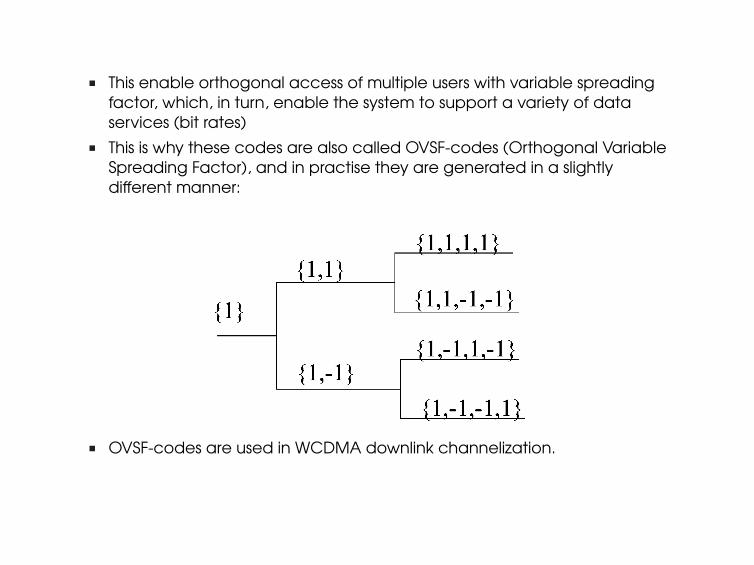
n This enable orthogonal access of multiple users with variable spreadingfactor, which, in turn, enable the system to support a variety of dataservices (bit rates)
n This is why these codes are also called OVSF-codes (Orthogonal VariableSpreading Factor), and in practise they are generated in a slightlydifferent manner:
n OVSF-codes are used in WCDMA downlink channelization.
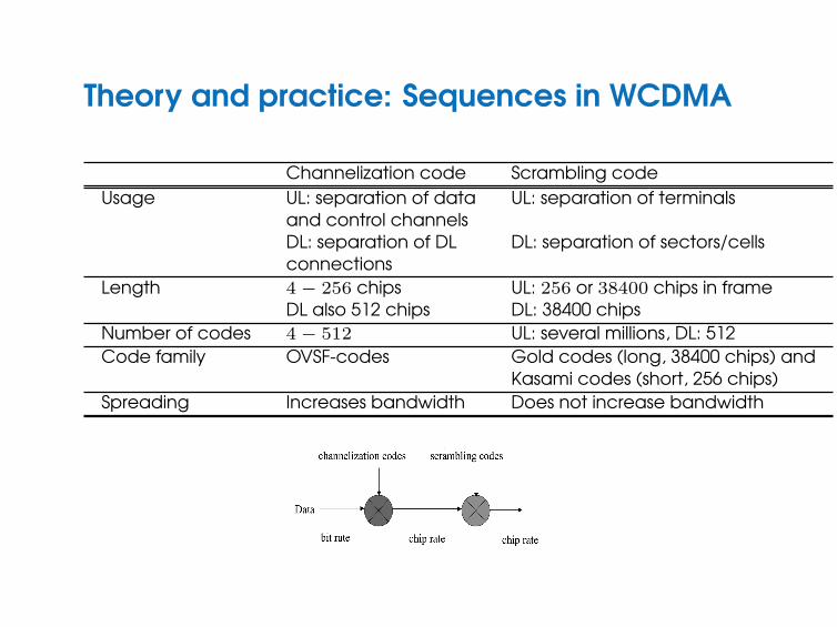
Theory and practice: Sequences in WCDMA
Channelization code Scrambling codeUsage UL: separation of data UL: separation of terminals
and control channelsDL: separation of DL DL: separation of sectors/cellsconnections
Length 4− 256 chips UL: 256 or 38400 chips in frameDL also 512 chips DL: 38400 chips
Number of codes 4− 512 UL: several millions, DL: 512Code family OVSF-codes Gold codes (long, 38400 chips) and
Kasami codes (short, 256 chips)Spreading Increases bandwidth Does not increase bandwidth