Time-of-flight spectroscopy and the Disk Chopper Spectrometer
21
Time-of-flight spectroscopy and the Disk Chopper Spectrometer John R.D. Copley NCNR Neutron Spectroscopy Tutorial December 4, 2007
Transcript of Time-of-flight spectroscopy and the Disk Chopper Spectrometer
Time-of-flight spectroscopy and the Disk Chopper Spectrometer
John R.D. Copley
NCNR Neutron Spectroscopy TutorialDecember 4, 2007
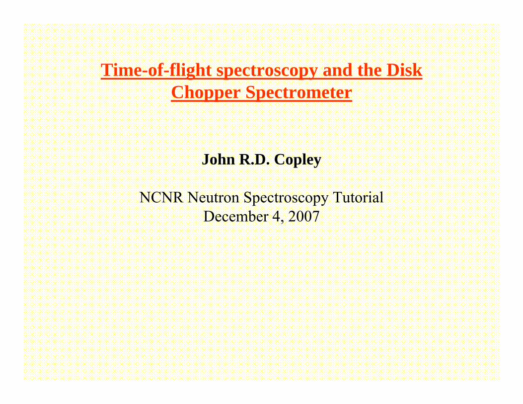
Time-of-flight spectroscopy
Detectors
SampleMonochromator
Pulser
SourceBeam stop
Beam monitor
Monochromatic bursts of neutrons strike the sample. Some of the neutrons are scattered.Some of the scattered neutrons are detected. The time between pulses, T, is divided into N time channels of
width Δ=Τ/Ν. (Αt the DCS, N=1000). Detector events are stored in a 2-d histogram I(i,j); i labels the detector, j labels the time channel.
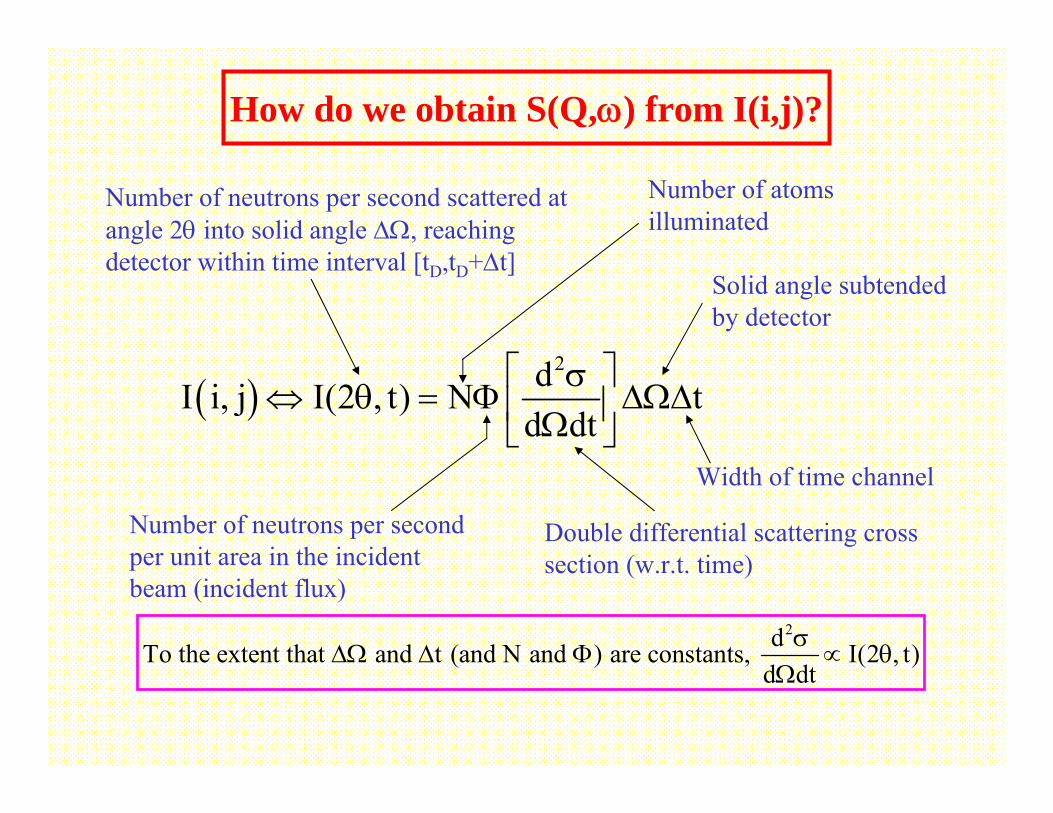
( )2dI i, j I(2 , t) N t
d dt⎡ ⎤σ
⇔ θ = Φ ΔΩΔ⎢ ⎥Ω⎣ ⎦
Number of neutrons per second scattered at angle 2θ into solid angle ΔΩ, reaching detector within time interval [tD,tD+Δt]
Number of atoms illuminated
Double differential scattering cross section (w.r.t. time)
Number of neutrons per second per unit area in the incident beam (incident flux)
Solid angle subtended by detector
Width of time channel
2dTo the extent that and t (and N and ) are constants, I(2 , t)d dt
σΔΩ Δ Φ ∝ θ
Ω
How do we obtain S(Q,ω) from I(i,j)?
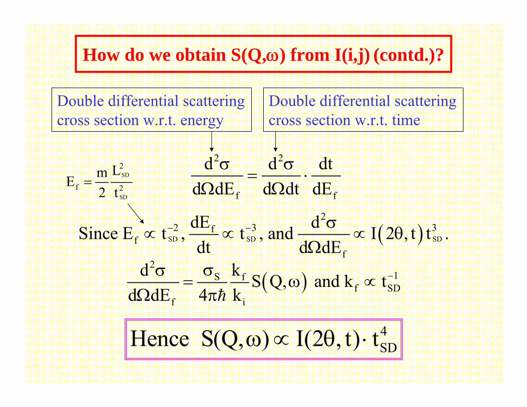
2 2
f f
d d dtd dE d dt dE
σ σ= ⋅
Ω Ω
( )2
1S ff SD
f i
kd S Q, and k td dE 4 k
−σσ= ω ∝
Ω π
( )SD SD SD
22 3 3f
ff
dE dSince E t , t , and I 2 , t t .dt d dE
− − σ∝ ∝ ∝ θ
Ω
Double differential scattering cross section w.r.t. energy
Double differential scattering cross section w.r.t. time
4SDHence S(Q, ) I(2 , t) tω ∝ θ ⋅
How do we obtain S(Q,ω) from I(i,j) (contd.)?
SD
SD
2
f 2
LmE2 t
=
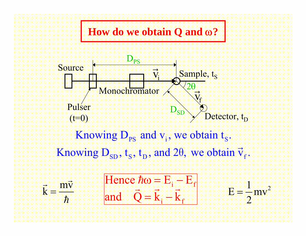
PS i S
SD S D f
Knowing D and v , we obtain t .Knowing D , t , t , and 2 , we obtain v .θ
2θ
DSD Detector, tD
Sample, tS
Monochromator
Pulser (t=0)
DPSSource
vf
How do we obtain Q and ω?
vi
i f
i f
Hence E Eand Q k k
ω = −= −
21E mv2
=mvk =
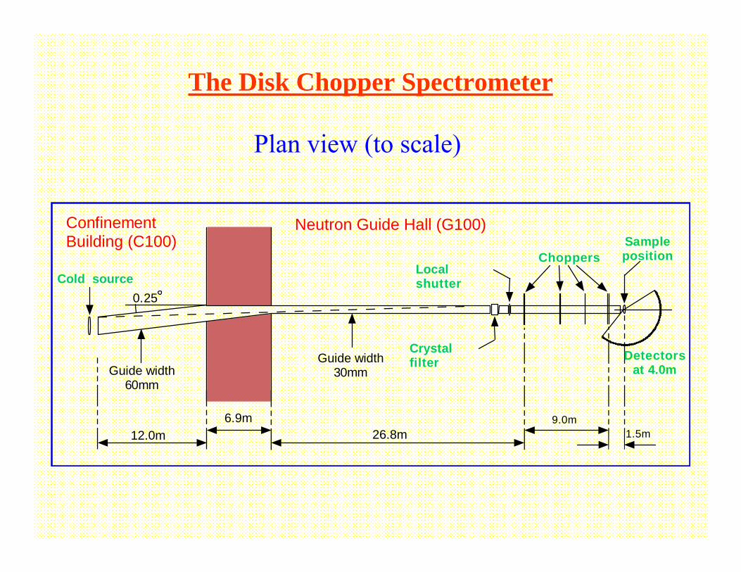
26.8m6.9m
12.0m
Guide width60mm
Guide width30mm
Cold sourceChoppers
Crystalfilter
Sampleposition
Neutron Guide Hall (G100)ConfinementBuilding (C100)
9.0m1.5m
Detectorsat 4.0m
0.25
Localshutter
Plan view (to scale)
The Disk Chopper Spectrometer
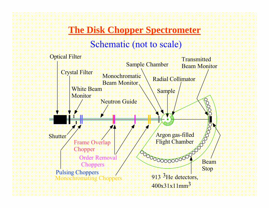
Neutron Guide
Optical FilterSample Chamber
913 3He detectors,400x31x11mm3
MonochromaticBeam Monitor Radial Collimator
Sample
Monochromating Choppers
Frame OverlapChopper
Order Removal Choppers
Pulsing Choppers
Argon gas-filledFlight Chamber
White BeamMonitor
Crystal Filter
TransmittedBeam Monitor
BeamStop
Shutter
The Disk Chopper SpectrometerSchematic (not to scale)
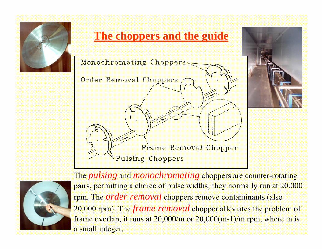
The choppers and the guide
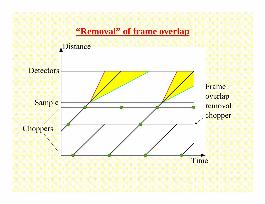
The pulsing and monochromating choppers are counter-rotating pairs, permitting a choice of pulse widths; they normally run at 20,000 rpm. The order removal choppers remove contaminants (also 20,000 rpm). The frame removal chopper alleviates the problem of frame overlap; it runs at 20,000/m or 20,000(m-1)/m rpm, where m is a small integer.
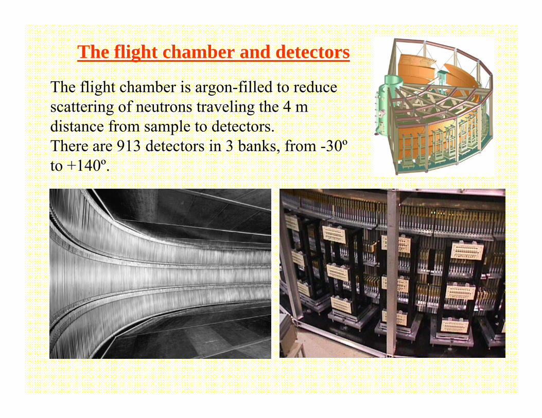
The flight chamber and detectors
The flight chamber is argon-filled to reduce scattering of neutrons traveling the 4 m distance from sample to detectors.There are 913 detectors in 3 banks, from -30ºto +140º.
What can one study using the DCS?
such as metals, insulators, semiconductors, glasses, magnetic materials, heavy fermions, superconductors, solid and liquid helium, plastic crystals, molecular solids, liquid metals, molten salts, biomolecules, water in confined geometries, polymer systems, micelles, microemulsions, etc., etc.,
See the NCNR annual reports for examples.
– the length and time scales (Q and ω ranges) are consistent with instrument capabilities
– the scattering (and absorption) cross sections are acceptable– the quantity of material is acceptable
such as (at the NCNR) T ≈50 mK to ≈1900K, P to ≈1.0 GPa, B to ≈11.5T, also strong electric fields, controlled humidity, etc., etc.,
Single particle and/or collective motions in all sorts of materials
under all sorts of conditions
provided that
http://www.ncnr.nist.gov/AnnualReport/

Considerations when running an experiment:
choice of wavelength, chopper speeds, and
resolution mode
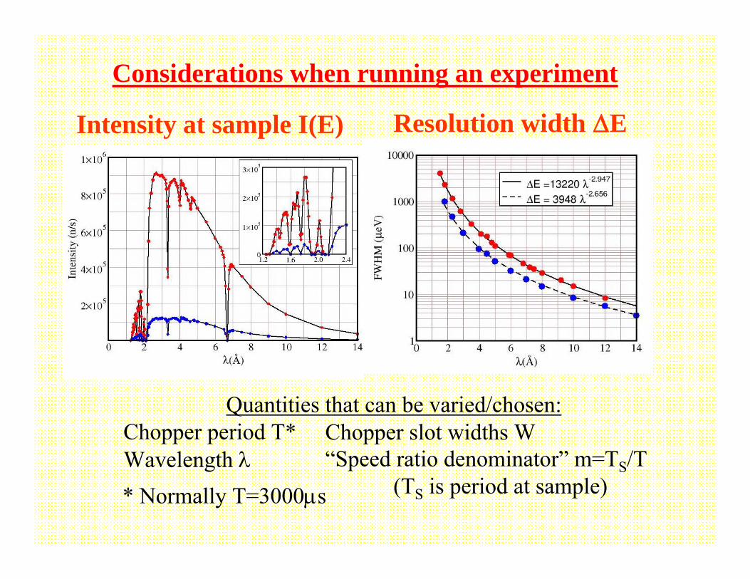
Considerations when running an experiment
Intensity at sample I(E) Resolution width ΔE
Quantities that can be varied/chosen:Chopper period T*Wavelength λ
Chopper slot widths W“Speed ratio denominator” m=TS/T
(TS is period at sample)* Normally T=3000μs
3
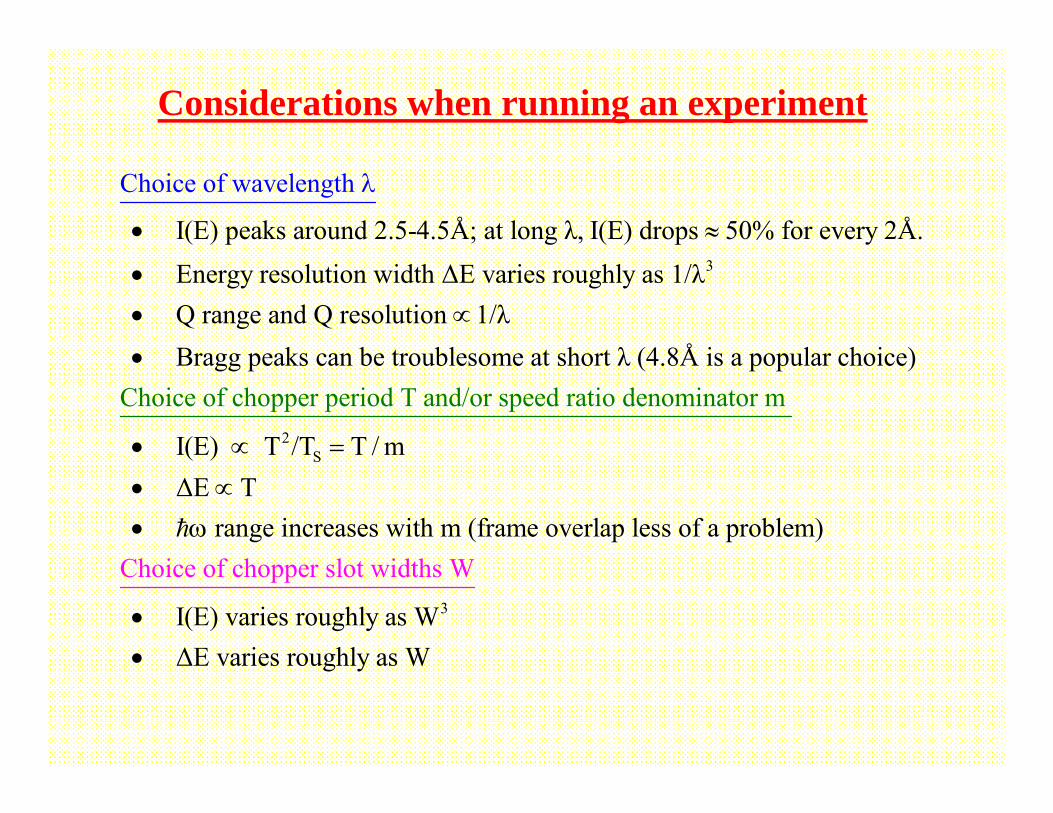
I(E) peaks around 2.5-4.5Å; at long λ, I(E) drops 50% for every 2Å. Energy resolution width ΔE varies roughly as 1/λ Q range and Q resolu
Ch
ti
oice o
o
f wavelen
n 1/λ Bragg pea
gth
k
s
• ≈
•∝
•
λ
•
2S
Choice of chopper period T and/or speed rati can be troublesome at short λ (4.8Å is a popular choice)
I(E) T /T T / m ΔE T range increases wit
o denominat
h m (frame
or
overlap le
m
ss
• ∝ =
• ∝• ω
3
of a problem)
I(E) varies roughly as
Choice of chopper slot widths
W ΔE varies roughly
W
as W••
Considerations when running an experiment
Time-distance diagrams
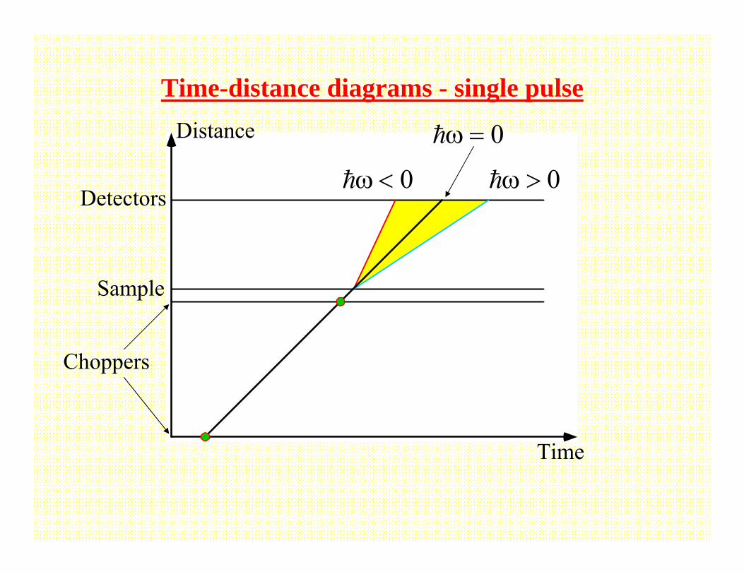
Time-distance diagrams - single pulse
Choppers
Sample
Detectors
Time
Distance
0ω <
0ω =
0ω >
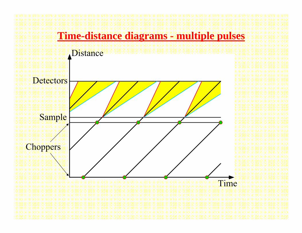
Time-distance diagrams - multiple pulses
Choppers
Sample
Detectors
Time
Distance
Choppers
Sample
Detectors
Time
Distance
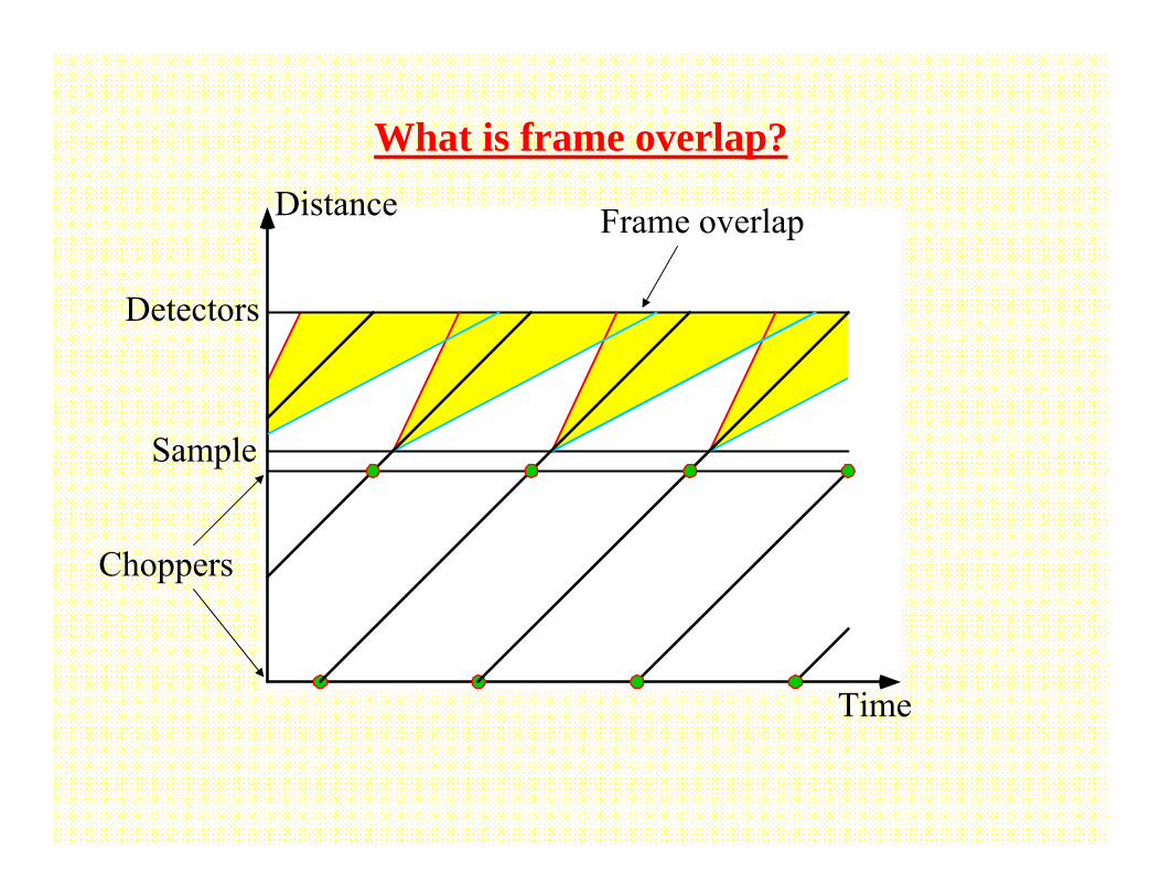
What is frame overlap?
Frame overlap
Choppers
Sample
Detectors
Time
Distance
“Removal” of frame overlap
Frame overlap removal chopper
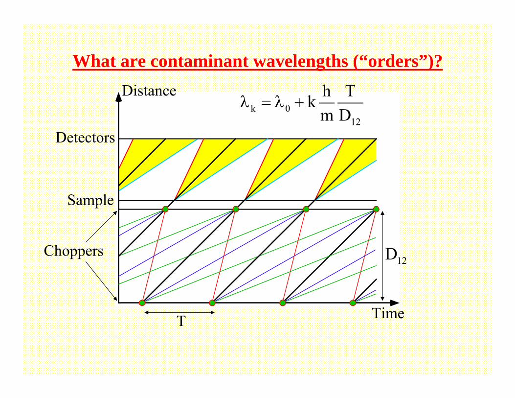
What are contaminant wavelengths (“orders”)?
Choppers
Sample
Detectors
Time
Distancek 0
12
h Tkm D
λ = λ +
12D
T
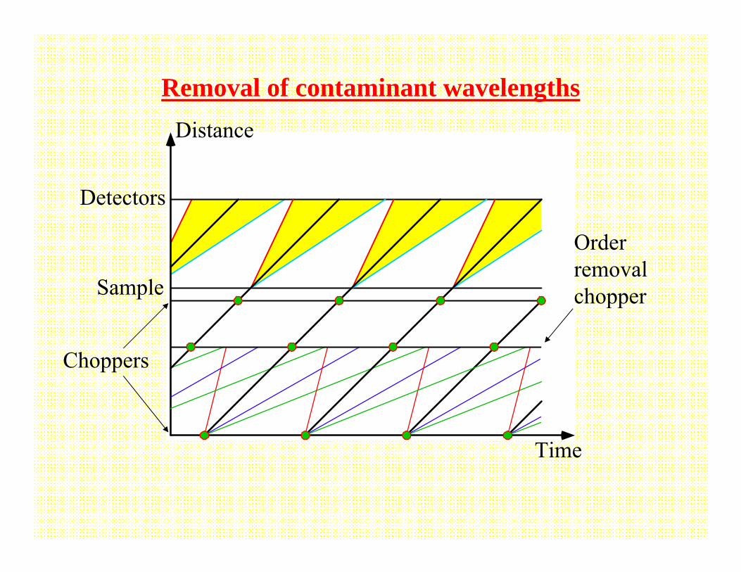
Choppers
Sample
Detectors
Time
Distance
Removal of contaminant wavelengths
Order removal chopper


![Windows 10 100% disk usage in Task Manager [SOLVED]Easy to Fix No Audio Output Device is Installed How to Fix Driver Power State Failure on Windows 10 Windows 10 100% disk usage in](https://static.fdocument.org/doc/165x107/5f385b2f42132f0a1f513402/windows-10-100-disk-usage-in-task-manager-solved-easy-to-fix-no-audio-output.jpg)