Thesis for the Undergraduate Section
95
` 1 | Page Subject Thesis «Verification of ship compliance according to industry Standards in Ship-to-Ship Transfer Operations» Thesis for the Undergraduate Section «Shipping trade and Business Services» Supervisor Professor Dr. Nikitas Nikitakos Co-Supervisor Mr. Ioannis Dagkinhs Undergraduate student: Anargyros Zenios Student registration number: 22110055 February 2016 Chios
Transcript of Thesis for the Undergraduate Section
`
1 | P a g e
Subject Thesis
«Verification of ship compliance according to industry Standards in Ship-to-Ship Transfer
Operations»
Thesis for the Undergraduate Section
«Shipping trade and Business Services»
Supervisor Professor
Dr. Nikitas Nikitakos
Co-Supervisor
Mr. Ioannis Dagkinhs
Undergraduate student: Anargyros Zenios
Student registration number: 22110055
February 2016
Chios
`
2 | P a g e
Θέμα Πτυχιακής Εργασίας
«Διαδικασία εξακρίβωσης συμμόρφωσης πλοίων συμφώνα με τις κατευθυντήριες γραμμές και
πρακτικές της αγοράς σε μεταφορτώσεις φορτίου δεξαμενοπλοίων μέσω Ship-to-Ship»
Πτυχιακή Εργασία Προπτυχιακού Τμήματος
«Τμήμα Ναυτιλίας και Επιχειρηματικών Υπηρεσιών - ΤΝΕΥ»
Επιβλέπων Καθηγητής
Δρ. Νικήτας Νικιτάκος
Συνεπιβλέπων Επόπτης
Κύριος Ιωάννης Δάγκινης
Προπτυχιακός Φοιτητής: Ανάργυρος Ζένιος
Αριθμός Μητρώου: 22110055
Φεβρουάριος 2016
Χίος
`
3 | P a g e
Θα ήθελα να εκφράσω τις ευχαριστίες μου στον επιβλέπων Καθηγητή μου Δρ. Νικήτα Νικητάκο για την
ευχάριστη, εποικοδομητική και εμπνευσμένη συνεργασία μας με σκοπό την επιτυχή ολοκλήρωση της
πτυχιακής μου εργασίας στο πλαίσιο της ολοκλήρωσης των σπουδών μου στο τμήμα Ναυτιλίας και
Επιχειρηματικών Υπηρεσιών.
Επιπλέον θα ήθελα να ευχαριστήσω τον Κύριο Ιωάννη Δάγκινη για την άμεση επιστροφή του στην
αλληλογραφία και παράλληλα την αμέριστη συμπαράσταση του σε ότι χρειάστηκα. Θα ήθελα επίσης να
ευχαριστήσω την DYNAMARINe για την γενναιόδωρη ανταλλαγή απόψεών και την χρήση του
στατιστικού δείγματος που μου επέτρεψαν να ενσωματώσω για να ενισχύσω την εργασία μου.
Καταληκτικά, θα ήθελα ολόψυχα να ευχαριστήσω την οικογένεια μου για την στήριξη και την συμβολή
τους με όποιο μέσω μπόρεσαν, ενάντια στους χαλεπούς και αντίξοους καιρούς που ζούμε.
Με σεβασμό προς όλους σας,
`
4 | P a g e
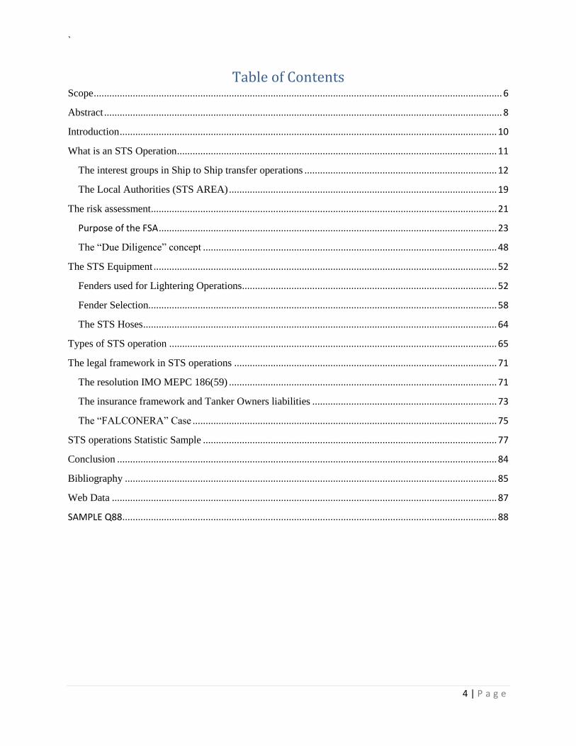
Table of Contents Scope ............................................................................................................................................................. 6
Abstract ......................................................................................................................................................... 8
Introduction ................................................................................................................................................. 10
What is an STS Operation ........................................................................................................................... 11
The interest groups in Ship to Ship transfer operations .......................................................................... 12
The Local Authorities (STS AREA) ....................................................................................................... 19
The risk assessment ..................................................................................................................................... 21
Purpose of the FSA .................................................................................................................................. 23
The “Due Diligence” concept ................................................................................................................. 48
The STS Equipment .................................................................................................................................... 52
Fenders used for Lightering Operations .................................................................................................. 52
Fender Selection...................................................................................................................................... 58
The STS Hoses ........................................................................................................................................ 64
Types of STS operation .............................................................................................................................. 65
The legal framework in STS operations ..................................................................................................... 71
The resolution IMO MEPC 186(59) ....................................................................................................... 71
The insurance framework and Tanker Owners liabilities ....................................................................... 73
The “FALCONERA” Case ..................................................................................................................... 75
STS operations Statistic Sample ................................................................................................................. 77
Conclusion .................................................................................................................................................. 84
Bibliography ............................................................................................................................................... 85
Web Data .................................................................................................................................................... 87
SAMPLE Q88 ................................................................................................................................................ 88
`
5 | P a g e
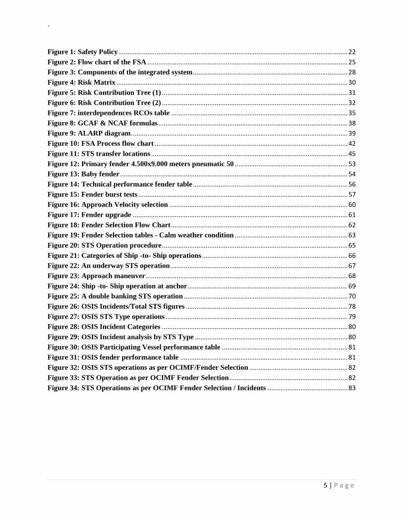
Figure 1: Safety Policy .............................................................................................................................. 22
Figure 2: Flow chart of the FSA .............................................................................................................. 25
Figure 3: Components of the integrated system ..................................................................................... 28
Figure 4: Risk Matrix ............................................................................................................................... 30
Figure 5: Risk Contribution Tree (1) ...................................................................................................... 31
Figure 6: Risk Contribution Tree (2) ...................................................................................................... 32
Figure 7: interdependences RCOs table ................................................................................................. 35
Figure 8: GCAF & NCAF formulas ........................................................................................................ 38
Figure 9: ALARP diagram ....................................................................................................................... 39
Figure 10: FSA Process flow chart .......................................................................................................... 42
Figure 11: STS transfer locations ............................................................................................................ 45
Figure 12: Primary fender 4.500x9.000 meters pneumatic 50 .............................................................. 53
Figure 13: Baby fender ............................................................................................................................. 54
Figure 14: Technical performance fender table ..................................................................................... 56
Figure 15: Fender burst tests ................................................................................................................... 57
Figure 16: Approach Velocity selection .................................................................................................. 60
Figure 17: Fender upgrade ...................................................................................................................... 61
Figure 18: Fender Selection Flow Chart ................................................................................................. 62
Figure 19: Fender Selection tables - Calm weather condition .............................................................. 63
Figure 20: STS Operation procedure ...................................................................................................... 65
Figure 21: Categories of Ship -to- Ship operations ................................................................................ 66
Figure 22: An underway STS operation ................................................................................................. 67
Figure 23: Approach maneuver ............................................................................................................... 68
Figure 24: Ship -to- Ship operation at anchor ........................................................................................ 69
Figure 25: A double banking STS operation .......................................................................................... 70
Figure 26: OSIS Incidents/Total STS figures ......................................................................................... 78
Figure 27: OSIS STS Type operations .................................................................................................... 79
Figure 28: OSIS Incident Categories ...................................................................................................... 80
Figure 29: OSIS Incident analysis by STS Type .................................................................................... 80
Figure 30: OSIS Participating Vessel performance table ..................................................................... 81
Figure 31: OSIS fender performance table ............................................................................................ 81
Figure 32: OSIS STS operations as per OCIMF/Fender Selection ...................................................... 82
Figure 33: STS Operation as per OCIMF Fender Selection ................................................................. 82
Figure 34: STS Operations as per OCIMF Fender Selection / Incidents ............................................ 83
`
6 | P a g e
Scope
As per the first lines of STS Lightering Clause 8.1 of Part 2 of the standard BPVOY4 form:
“Charterers shall have the option of transferring the whole or part of the cargo…to or from any
other vessel including, but not limited to, an ocean-going vessel, barge and/or lighter (the
"Transfer Vessel")…. All transfers of cargo to or from Transfer Vessels shall be carried out in
accordance with the recommendations set out in the latest edition of the "ICS/OCIMF Ship to
Ship Transfer Guide (Petroleum)".”
The compliance of the vessels which presented in Charter Parties was answered with a YES or
NO through Q88 and HVPQ at question 8.26 and 13.1.1 respectively. Apparently, a YES answer
from Technical Operator indicates that subject vessel satisfies the requirement as outlined in the
latest edition of the "ICS/OCIMF/SIGTTO/CDI Ship to Ship Transfer Guide for Petroleum,
Chemicals and Liquefied Gases” edition 4 2013. Notwithstanding the obvious, technical
operators undertake a “burden” of responsibility to ensure to their commercial operators and
charterers as well that compliance is being reflected simultaneously at their actions to prove it.
In this study thesis the combination of safety culture, procedures and best practices will be
presented in order to verify whether YES is substantial. Specifically, the verification process
includes elements and best practices which are flown from the latest OCIMF guidelines edition
4th 2013.
In this respect the scope of each section of the thesis:
The scope of the first section “what is an STS operation” is to address the definition of the
transshipment of cargo via STS operation. Prescribes the role and the required characteristics of each
vessel at each STS type procedure. Furthermore, prescribes thorough the role, duties, obligations and
requirements of the involved STS parties.
The scope of the second section “The Risk Assessment” is to address the risk theory and define the risk
according to IMO’S FSA procedure analysis. Prescribes the types and approaches of a risk assessment.
Furthermore, presents the essential STS elements that should be taken into consideration during the
preparation of the STS risk assessment by the technical operators of the involved vessels and the
nominated service provider.
The scope of the third section “The STS equipment” is to address the characteristics and industry best
standards of the fenders (Yokohama Pneumatic Rubber) and hoses. Furthermore, at the section is
prescribed the positioning and the selection process of the primary and secondary fenders according to
the latest OCIMF Guidelines.
`
7 | P a g e
The scope of the fourth section “The STS Types” is to describe the three major types of STS performed
by seagoing tankers. The STS procedure might execute underway, at anchor or alongside jetty. The
description of each procedure as well as the requirements of each vessel are described accordingly.
The scope of the fifth section “The legal framework in STS operations” is to address the establishment
of the regulatory framework in STS operations. Prescribes, how this affect the stakeholders of the
industry. Furthermore, presents the insurance aspect and relations of the insurer and the insured in case
of a collision. Last but not least, presents the “FALCONERA CASE”. The FALCONERA case consists a case
which presents a rejection of nominated by charterers’ vessels by the technical operators. The final
judgment clarifies when a STS transfer operation is acceptable.
The sixth section “STS Operation Statistic Sample” was taken by a Greek STS industry representative
company, DYNAMARINe. Presents STS statistic sample produced by the STS assessments completed by
the Masters of the involved vessels (not only customer vessels).
As an appendix section, a Q88 of a sample vessel.
Key words: STS (Ship-to-Ship) transfer, risk, risk assessment, procedures, policies, liabilities, STS Plan,
OCIMF, Guidelines
`
8 | P a g e
Abstract
The “Ship-to-Ship” transfer operation term is defined as the transshipment of oil cargo or oil products
quantity between seagoing tankers. Specifically, the candidate tankers positioned alongside each other
either while one of them is at anchor or underway or by a jetty when one vessel will act as the terminal
whilst the other one will berth alongside the other vessel. Actually, STS transfer methods include also
liquefied GAS (LPG or LNG) as well as bulk cargo. The chronical of this practice for seagoing tankers,
started back to 60’s when the dimensions and displacement of tankers increased, while the terminal
existing draft posed restrictions in berthing alongside, especially in USA ports. In this regard, the STS
procedure or otherwise “lightering” process -as those days was address-, continues nowadays to be not
only overcoming terminal restrictions but also constitutes on worldwide distribution of oil commodities
as well as a trading tool for cargo owners.
Since the transfer of oil/ chemical and product cargos via STS has been regulated through the IMO
resolution, MEPC 186(59)/2009 (the new MARPOL chapter 8 of Annex 1) [Ref xxx], inevitably the full
operational responsibility has been “shifted” to vessel technical operators. In order to reduce the
possibility of a potential incident or even accident with severe effects, the “due diligence” concept
during ensuring safety should be adopted by the tanker owners and an STS risk assessment became
necessary for the evaluation of the hazards.
Prevailing Industry guidelines are those denoted by the OCIMF/ICS……. As presented at the latest edition
of 2013. The scope of the guidelines is to describe a safe way of organizing and conducting such
operations and the role of involved stakeholders. Since the first edition of 1977, these guidelines are
always referenced in the STS and relevant riding clauses of Charter Parties between charterers and ship
owners.
Amongst the stakeholders that are usually responsible for organizing an STS operation are the charterers
and/or their cargo owners. When the location or the area is specified, all parties (Charterers, cargo
owners, Shipowners and Masters) should agree at specific elements that affect the safe conduct of the
STS operation. The feasibility, the assurance of safety and a detailed and safe planning are essential
procedures in order to arrange such operation.
For sake of a good planning, it is essential to ensure that the selection of the STS equipment that will be
utilized for the transshipment will be in compliance with the current industry standards. The STS
equipment will be provided either from the nominated STS Service provider or from one of the involved
ships. A person in overall advisory control (POAC) shall provide assistance and advises during the
transshipment. The POAC could be either a Master of the involved ships or an appointed by the Service
provider qualified person. Among the qualifications of the POAC –addressed by the Manual of Oil
Pollution chapter section 1, chapter 6, are his experience on relevant type of tankers as well as hιs
experience on local geographical particularities.
Furthermore, directly or indirectly local Port Authorities as well as insurers are involved in such STS
operations. The costal authorities have the right and the responsibility for the environmental protection
inside the entire Exclusive Economic Zone. In light of this, they have the right to monitor and supervise
`
9 | P a g e
such operations in this area. In this respect, the port authorities might develop dedicated Emergency
Contingency plan and adopt also local regulations which direct the procedures of STS operations at their
territorial waters. Therefore, the communications of the vessels with the authorities should be prompt
and in order to gain approval of access and according to the requirements of the regulation.
The insurers require the assurance of ship owners, that the quality standards during an STS operation
will and that safety issues will not be compromised.
In conclusion, the transshipment of oil cargoes via STS operation implies a risk of pollution with severe
consequences due to the nature of the product. All environmental aspects, other contributing factors
and STS elements should be taken into consideration during the arrangement of such operation. Sound
management should exist from involved parties and the exercise of the due diligence by ship owners is
required in order to allow to them to ensure safety and be able to prove that they do so. The detailed
planning, experienced crew, suitable STS equipment, policies and procedures from ship owners with
commitment to a safety culture is the key of successful and risk free STS operation.
`
10 | P a g e
Introduction
After the implementation of IMO MEPC 186(59) 2009, Tanker Owners and technical operators
are responsible for safety during the transfer of cargo via Ship-to Ship. In this respect, policies
and procedures have been implemented and approved by recognized organizations.
The concept of the due diligence policy has been exercised by Technical Operators in order to
review the suitability of the participating vessel. During this process which is known as
screening procedure, Technical Operators taking into account factors which are prescribed in this
dissertation and associated with risk mitigation measures prior the acceptance and
commencement of the STS operation. The evaluation of risk should be determined with respect
to the following elements:
Ships technical and statutory condition or deficiencies.
Ship Compatibility.
Ships compliance with the Latest OICIMF Guidelines.
STS Plan and flag requirements.
Past STS performance of the Technical Manager and the screened vessel.
PSC performance (Manager and Vessel).
Crew experience (Human element).
STS equipment.
Local geographical restrictions.
Weather Conditions.
Subject dissertation is aimed to present the commercial and legal framework in STS operations,
related to the compliance of the nominated by charterers vessels. In this respect Technical
managers should exercise their due diligence as per industry guidelines, at the best of their
knowledge, after the acceptance of the nominated vessel and the finalization of the STS
operation. Further to previously mentioned, tanker owners should provide advises to their
Masters as well as risk mitigation measures which produced during the preparation of the STS
risk assessment prior the commencement of each STS operation. Tanker owners and their
Masters should always bear in mind that, “The Master of each vessel shall always remain in
command of his vessel crew, cargo, and shall under no circumstances permit safety to be
jeopardized by the actions of others”
`
11 | P a g e
What is an STS Operation
Definition
A Ship-to-Ship transfer operation is a procedure in which Ocean-going (150 Gross Tonnage)
vessels engaged in the transfer of a defined quantity of cargo at sea. On this paper the
examination is oriented on vessels carrying crude oil and petroleum products, chemicals,
liquefied petroleum gas (LPG) and liquefied natural gas (LNG) or lightering operations.
Maneuvering Vessel
A lightering operation contains a very strict procedure as depicted at the latest recommendations
included at ICS/OCIMF/SIGTTO/CDI “Ship to Ship Transfer Guide, for Petroleum, Chemicals
and Liquefied Gases” First Edition 2013. The maneuvering vessel which is customary the
smaller vessel, approaches the constant heading (underway STS) ship and maneuvered alongside
the Mother vessel (the larger vessel) at slow speed (typically about knots) for mooring
operations1. The berthing procedure should take into consideration the technical characteristics
of the vessels. In this respect the maneuvering vessel with a right-handed propeller, approaching
from behind it is the impact of a transverse thruster will lead in maneuvering and berthing with
her port side to the starboard side of the constant heading ship.
During maneuvering procedure the following should be taken under consideration:
Safety first: In case there is doubt from both Masters or the STS Superintendent that
safety during maneuvering could be jeopardized, the berthing operation should be
terminated.
Maneuvering characteristics of both ships: It is clear that involved ships might have
different maneuvering characteristics. In this respect it has to be ensured that an optimum
approach will be performed. A common approach requires to keeping the wind and sea
on the port bow of the constant heading ship and keeping the wind and swell on the port
bow of same as well.
1 ICS/OCIMF/SIGTTO/CDI “Ship to Ship Transfer Guide, for Petroleum, Chemicals and Liquefied Gases” First Edition 2013,
Glossary x.
`
12 | P a g e
Angle of approach: The maneuvering vessel should not excess the angle of approach.
RPM of the main engine of the constant heading ship: The RPM of the constant
heading ship should be fixed and should not be changed unless the STS superintended or
the Master of the maneuvering vessel requested.
Effect of ship interaction at close quarter: Vessels’ interaction should be anticipated.
In order to offset interaction and keep effective heading control, it has to be ensured that
the main engine(s) of the maneuvering ship will be kept turning ahead or, if fitted with a
controllable pitch propeller, maintain positive propeller pitch throughout.
Capability of maneuvering at slow speeds of 5 knots: On underway STS operations,
nominate vessels should be capable of conducting maneuvers at slow speeds of 5 knots or
less without the possibility of main engine black out. In this regard the maneuvering
vessel should.2
The interest groups in Ship to Ship transfer operations
Undoubtedly, in order to conduct an effective STS operation, several aspects should be taken
into consideration. The process starts with the Cargo owner or the Charterer who announce the
intention of conducting an STS procedure with a nominated participating vessel, to the owners
(Technical operator or ISM Manager) of the chartered vessel. Thereafter, Cargo Owner/Charterer
is responsible for appointing an STS Service provider which will provide the appropriate and fit
for purpose STS equipment and propose an STS location. In this regard, the above-mentioned
outlined the following principal interest groups:
1. The Cargo Owner or the Charter as STS Organizer.
2. The Owners (Technical Operators or ISM Managers).
3. The participating Vessels (discharging/receiving) including their Crew.
4. The STS Service Provider.
5. The Local Authorities (STS AREA).
Various risks are evident when engaging in STS operations, such as the physical safety of the
participating vessel, to the crew and the risk of oil spillage. In each case the liability remains
2 ICS/OCIMF/SIGTTO/CDI “Ship to Ship Transfer Guide, for Petroleum, Chemicals and Liquefied Gases” First Edition 2013,
page 11.
`
13 | P a g e
always with the Masters of the vessels who have the authority to abort the operation in case
safety jeopardized.
The Cargo Owners
The cargo owners have the ownership of the cargo quantity transferred via STS operation. The
cargo owners have an indirect link to the whole process. Nevertheless, in case pollution
occurred, due to accident, the cargo owners burdened with the “cost” of bad reputation.
The charterer
The charterer is the contracting party that concluded the charter-party. The Charterer (or the
Cargo Owner) is the entity that settles and organizes an STS operation and appoints an STS
Service Provider as well. More Specifically, as per BIMCO Ship to Ship Transfer Clause for
Time Charter Parties:
Risk, cost, expense, time and insurance policy extension: The Charterers shall have the
right to order the Vessel to conduct ship to ship cargo operations, including the use of
floating cranes and barges. All such ship to ship transfers shall be at the Charterers’ risk,
cost, expense and time. Furthermore, if the Owners are required to extend their existing
insurance policies to cover ship to ship operations or incur any other additional
cost/expense, the Charterers shall reimburse the Owners for any additional premium or
cost/expense incurred.
Responsibilities: The Charterers shall direct the Vessel to a safe area for the conduct of
such ship to ship operations where the Vessel can safely proceed to, lie and depart from,
always afloat, but always subject to the Master’s approval. The Charterers shall provide
3adequate fendering, securing and mooring equipment, and hoses and/or other equipment,
as necessary for these operations, to the satisfaction of the Master.
Permissions from the authorities: The Charterers shall obtain any and all relevant
permissions from proper authorities to perform ship to ship operations and such
operations shall be carried out in conformity with best industry practice.
3 www.bimco.org , “STS transfer Clause”, last update on 09.12.08.
`
14 | P a g e
Master’s overriding authority: If, at any time, the Master considers that the operations
are, or may become, unsafe, he may order them to be suspended or discontinued. In either
event the Master shall have the right to order the other vessel away from the Vessel or to
remove the Vessel.
STS consequences: The Charterers shall indemnify the Owners against any and all
consequences arising out of the ship to ship operations including but not limited to
damage to the Vessel and other costs and expenses incurred as a result of such damage,
including any loss of hire; damage to or claims arising from other alongside vessels,
equipment, floating cranes or barges; loss of or damage to cargo; and pollution.4
The discharging vessel
The vessel which will transfer a definite cargo quantity to the receiving vessel may also refer as
the Ship to be lightered (STBL).5
The lightering Vessel
The vessel which will receive a definite cargo quantity from the discharging vessel may also
refer as the lightering vessel.6
The Ship owner
The ship owner of the vessel which might differs from head owner or the ship manager of the
vessel is actually the operator who has the day-by-day operational and technical control of the
vessel which according to industry refers as Technical Operator or ISM Manager. The Technical
Operator requires providing a ship with specific industry characteristics. More specifically,
Technical Operator is responsible to provide a vessel which complies de facto with the
Guidelines/Recommendations as per the latest OCIMF ICS/OCIMF/SIGTTO/CDI “Ship to Ship
Transfer Guide, for Petroleum, Chemicals and Liquefied Gases” First Edition 2013. For instance,
good quality mooring equipment, it is important that ships engaged in STS are equipped with:
4 www.bimco.org , “STS transfer Clause”, last update on 09.12.08.
5 ICS/OCIMF/SIGTTO/CDI “Ship to Ship Transfer Guide, for Petroleum, Chemicals and Liquefied Gases” First Edition 2013,
Glossary IX. 6 ICS/OCIMF/SIGTTO/CDI “Ship to Ship Transfer Guide, for Petroleum, Chemicals and Liquefied Gases” First Edition
2013, Glossary X.
`
15 | P a g e
I. Well placed and adequate closed chocks/fairleads.
II. Well maintained and sufficient number of moorings lines (ropes, wires-wire tails).
III. Efficient Winches and bollards well placed.7
The STS Organizer
According to latest STS OCIMF guidelines an STS Organizer “is a shore based operator
responsible for arranging an STS transfer operation. The Organizer may be an STS Service
Provider.”
The term “STS ORGANISER” is referenced in four separate sections throughout the latest
OCIMF guidelines and in many cases this particular term is confused with the role of the STS
Service Provider.
The STS organizer can be,
The charterer/cargo owner who decides on the cargo transfer and charter for both
participating vessels.
The STS Service Provider who takes responsibility to assist the STS Operation with the
necessary technical and advisory resources.
The Technical operator who manages a vessel involved in an STS Operation.
The definition of the STS Service Provider is explained at the latest OCIMF guidelines as
“Companies sometimes employed to organize and assist with STS transfers. The services offered
by these companies vary, but often include the provision of personnel and equipment to facilitate
the STS transfer. The STS Service Provider may also supply the essential personnel and
equipment needed, such as hoses, fenders and support craft. The STS Service Provider may also
be referred to as an STS Contractor or STS Resource Provider.”
The term “STS ORGANISER” appears at the following sections of latest OCIMF STS
guidelines8:
7 ICS/OCIMF/SIGTTO/CDI “Ship to Ship Transfer Guide, for Petroleum, Chemicals and Liquefied Gases” First Edition 2013,
page 82. 8 DYNAMARINe & Clyde & Co “Frequently Asked Questions in Ship to Ship transfer Operations”, page 22, Q 16.01, March
2016.
`
16 | P a g e
A. At section 4.3 mentioned as “the STS organizer generally provide pre-arrival information to
nominated ships. The STS organizer may be the operator of the ships if carrying out in-house
operations, or may be an STS Service provider. Normally such providers send advance STS
instructions to the ships concerned.”
According to this section the STS ORGANISER will inform both participating vessels for all
necessary information prior the STS operation. This information is described in detail at section
4.3.2 of latest OCIMF guidelines. The understanding is that this is a responsibility of the
Charterer/Cargo Owner who arranges for the STS Operation. Once an STS Service Provider is
contracted for the technical assistance and needed resources, he acts on behalf of the Charterer as
the STS ORGANISER.
B. At section 9.1.3 of the latest OCIMF guidelines reference is made to the verification of age of
utilized fenders by the master, shipping company or STS organizer, and if these are provided by
an STS service provider. In this reference the “STS ORGANISER” is a different entity from that
of the STS Service provider since the age of fenders should be “ascertained” prior to use.
Therefore it is concluded that in this case the STS Organizer is the charterer/cargo owner, or a
Tanker commercial operator.
C. At the second to the last paragraph of section 9.1.3 the following is mentioned: “It is the
responsibility of the STS organizer to determine the fender requirements and to agree these with
all other parties involved.”
The parties involved at an STS Operation are the Technical operator and his Master, the STS
Organizer and STS Service Provider. In this case, if the STS Service Provider and STS
Organizer are the same entity, then fenders should be agreed upon between the Service Provider
and the Master. If the STS organizer is the charterer/cargo owner then he should determine
fender requirements and agree with those of the Service Provider and the Master.
From above paragraphs, it is clear that the "STS ORGANISER", as a term, is in fact confusing
since in most cases it reflects the duties of the STS Service Provider. The STS ORGANISER is
the entity that "ORGANISES" an STS operation. In simple terms, it decides on both participating
`
17 | P a g e
vessels, the STS location and Service Provider.9 The confusion in his role, in conjunction with
the role of the STS Service Provider, is a result of the charterer duties and responsibilities
denoted within the STS clauses of various charter parties. The STS Service Provider is a servant
to the Charterer/ Cargo Owner and as such he undertakes to provide the appropriate resources for
the safe completion of the STS operation.
Having mentioned the above, as a matter of consistency, it is proposed that all STS Stakeholders
have the STS Organizer well defined prior each STS Operation. In doing so, tanker operators
should request from their brokers/ charterers to revert with the STS ORGANISER full style prior
the commencement of the STS Operation.
The STS Service provider
STS providers are nominated by STS organizer and are responsible to provide the necessary
equipment in sound condition, fit for purpose and in compliance with industry requirements.
Furthermore, arrange and 10
appointed an nominated POAC (Person in Overall and Advisory
control) to superintend the STS operation an advise the Master accordingly. Service provider and
POAC bear no liabilities with respect to the safety of the STS operation and do not relieves the
Vessel’s Master of any of their duties, requirements or responsibility.11
Person in Overall Advisory Control (POAC)
The POAC is responsible for the approach and mooring of the two ships, using the appropriate
equipment. According to IMO MEPC 186(59) and the Oil pollution manual Section 1,
Prevention of pollution, the qualifications and duties of the POAC have clearly defined in order
to set the minimum standards in the industry and therefore regulate the involvement of such
personnel. According to industry minimum standards the POAC have to fulfil below
requirements as depicted at Manual on Oil pollution Section I – Prevention. The Administration,
9 DYNAMARINe & Clyde & Co “Frequently Asked Questions in Ship to Ship transfer Operations”, page 22, Q 16.01,
March 2016. 10
ICS/OCIMF/SIGTTO/CDI “Ship to Ship Transfer Guide, for Petroleum, Chemicals and Liquefied Gases” First Edition 2013,
page 5. 11
ICS/OCIMF/SIGTTO/CDI “Ship to Ship Transfer Guide, for Petroleum, Chemicals and Liquefied Gases” First Edition 2013,
Glossary xi.
`
18 | P a g e
cargo owners or oil tanker’s operators should agree and designate the POAC who must have at
least the following qualifications12
:
1. Holds an appropriate management level deck license or certificate meeting international
certification standards, with all STCW and dangerous cargo endorsements up to date and
appropriate for the ships engaged in the STS operation;
2. Attendance at recognized ship-handling course;
3. Conduct of a suitable number of mooring/unmooring operations in similar circumstances and
with similar vessels;
4. Experience in oil tanker cargo loading and unloading;
5. A thorough knowledge of the geographic transfer area and surrounding areas;
6. A knowledge of spill clean-up techniques, including familiarity with the equipment and
resources available in the STS contingency plan; and
7. Thorough knowledge of the STS Plan.
POAC’s duties follows as these depicted at manual oil pollution Chapter 6 (Ship-to-ship transfer
of crude oil and petroleum products while underway or at anchor)
1. Ensure that the cargo transfer, mooring and unmooring operations are conducted in
accordance with the required STS plan, the contents of this chapter of the Manual and
take into account the recommendations contained in the industry publication ’Ship to
Ship Transfer Guide – Petroleum’;
2. Advise the Master(s) of the critical phases of the cargo transfer, mooring and unmooring
operation;
3. Ensure the provisions of the contingency plan are carried out in the event of a spill;
4. Ensure that all required reports are made to the appropriate authorities;
5. Ensure that crew members involved in each aspect of the operation are properly briefed
and understand their responsibilities;13
12
IMO Manual on Oil Pollution Section I – “Prevention, Ship-to-Ship transfer of crude oil and petroleum products while
underway or at anchor”, page 62.
`
19 | P a g e
6. Ensure that approach and mooring operations are not attempted until proper effective
communication has been confirmed between the two oil tankers and appropriate checks
have been completed;
7. Ensure that a pre-transfer STS safety check is undertaken in accordance with accepted
industry guidance; and
8. Ensure that appropriate checks are undertaken prior to unmooring.
At this point it has to be highlighted the fact that there are currently no international standards for
STS Service providers. In order to verify and ensure that the STS operation will conduct safely,
reliably and efficiently performance records and previous industry experience may be important
when assessing an STS service provider’s ability to meet customer and regulatory requirements.
STS Service providers should bear in mind that may be subject to assessment by users of their
services.
As a verification tool of their safety management system (SMS) self-assessment process can be
used by service providers in order to mitigating risks in STS operations and simultaneously
improves their management systems.14
The Local Authorities (STS AREA)
As per article 56 of United Nations Convention on the Law of the Sea, in the exclusive economic
zone (EEZ) the Costal State has jurisdiction as provided for provided for in the relevant provisions
of this convention with regard to the protection and preservation of the marine environment.
This is the reason why coastal authorities may have prepared an Emergency Contingency Plan
and may also issue and apply local regulations.
In this respect, according to OCIMF latest guidelines notification to local authorities is required
not less than 48 hours in advance of the scheduled operation. The notification should include the
following:
Name, flag, call sign, IMO number and estimated time or arrival (ETA) of the oil tankers
involved in the STS operations.
13
IMO Manual on Oil Pollution Section I – “Prevention, Ship-to-Ship transfer of crude oil and petroleum products while
underway or at anchor”, page 63 14
ICS/OCIMF/SIGTTO/CDI “Ship to Ship Transfer Guide, for Petroleum, Chemicals and Liquefied Gases” First Edition 2013,
page 17.
`
20 | P a g e
Date, time and geographical location at the commencement of the planned STS
operations.
Whether STS operations are to be conducted at anchor or underway.
Oil type and quantity.
Planned duration of the operation.
Identification of the Service provider or person in overall advisory control (POAC) and
contact information.
Confirmation that the oil tankers have an approved STS operations plan.
If the estimated time of arrival of an oil tanker at the location or area for the
STS operations changes by more than six hours, the master, owner or agent of that oil tanker
shall provide a revised estimated time to the relevant Authority.
It seems reasonable the fact that the “suitability” of the STS Area depends on the type of STS
operation. In this respect, it will play crucial role whether an STS operation is underway. More
specifically, an underway STS operation case, demands a larger transfer area in order to facilitate
maneuvers at sea. It is also obvious that in case the approach conducted at port limits the STS
requires a smaller area.15
Summarizing, for a determine operational management, during the selection of the STS Area the
STS organizer should take into consideration the undermentioned:
Notification and approval from the authorities: In order to identify local restrictions
and regulations.16
Local legislative requirements.17
Weather forecasts: Presented weather conditions forecasts18
15
ICS/OCIMF/SIGTTO/CDI “Ship to Ship Transfer Guide, for Petroleum, Chemicals and Liquefied Gases” First Edition 2013,
page 14, 15. 16
ICS/OCIMF/SIGTTO/CDI “Ship to Ship Transfer Guide, for Petroleum, Chemicals and Liquefied Gases” First Edition 2013,
page 96. 17
ICS/OCIMF/SIGTTO/CDI “Ship to Ship Transfer Guide, for Petroleum, Chemicals and Liquefied Gases” First Edition 2013,
Section 3, page 22. 18
ICS/OCIMF/SIGTTO/CDI “Ship to Ship Transfer Guide, for Petroleum, Chemicals and Liquefied Gases” First Edition 2013,
page 21.
`
21 | P a g e
Visibility: In order to avoid collisions and ensure safety of navigation during the
maneuvering, the visibility should be sufficient and verifying with ship’s personnel that
conditions are satisfied for approach, mooring and cargo transfer.
Wind speed, and direction: Wind speed and direction in conjunction with waves can
influence vessels interactions.
Wave and swell height, period and direction: Although monitoring wave and swell are
important, weather limitations under which STS transfer operations can be conducted will
be impractical. Attention drawn with respect to the effect on the fenders or mooring lines
and the rolling movements induced in the participating vessels, taking into account the
relative freeboard and displacement.
The risk assessment
The risk assessment process
The development of Risk Theory starts in the late 60s and early 70s from the nuclear and
chemical industries. The increasing potential consequences of an accident forced the researchers
to manage the risk in structured and scientific way. In the maritime industry the risk was
introduced in the 80s 90 of shore oil industry). The risk assessment process finalized and adopted
from maritime companies as methodology for decision making in the early 90s.
Traditionally risk defined as the probability for a phenomenon to occur multiplied by the
consequences (or impacts). Within maritime transport frequency is used instead of probability
so,
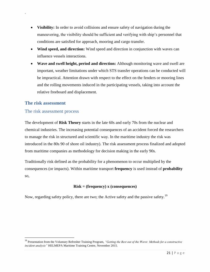
Risk = (frequency) x (consequences)
Now, regarding safety policy, there are two; the Active safety and the passive safety.19
19
Presentation from the Voluntary Refresher Training Program, “Getting the Best out of the Worst: Methods for a constructive
incident analysis” HELMEPA Maritime Training Centre, November 2015.
`
22 | P a g e
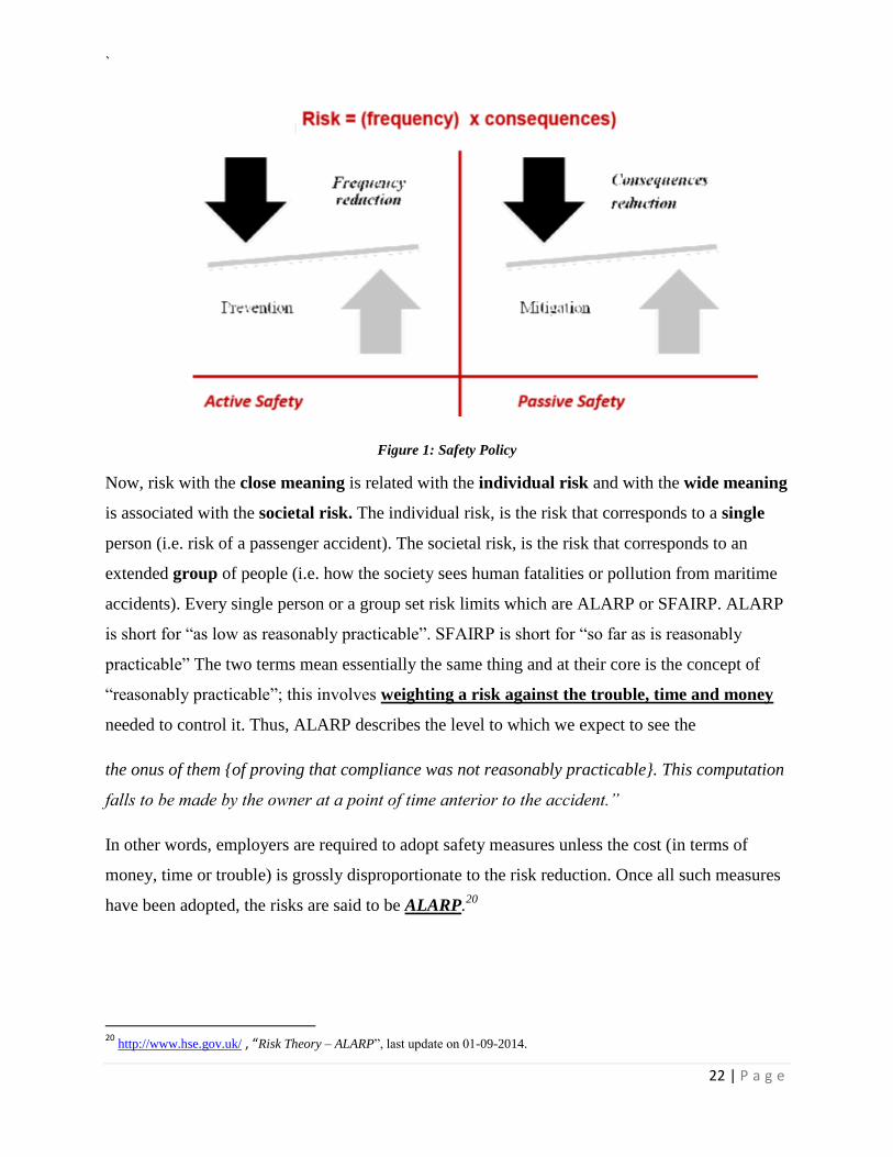
Figure 1: Safety Policy
Now, risk with the close meaning is related with the individual risk and with the wide meaning
is associated with the societal risk. The individual risk, is the risk that corresponds to a single
person (i.e. risk of a passenger accident). The societal risk, is the risk that corresponds to an
extended group of people (i.e. how the society sees human fatalities or pollution from maritime
accidents). Every single person or a group set risk limits which are ALARP or SFAIRP. ALARP
is short for “as low as reasonably practicable”. SFAIRP is short for “so far as is reasonably
practicable” The two terms mean essentially the same thing and at their core is the concept of
“reasonably practicable”; this involves weighting a risk against the trouble, time and money
needed to control it. Thus, ALARP describes the level to which we expect to see the
the onus of them {of proving that compliance was not reasonably practicable}. This computation
falls to be made by the owner at a point of time anterior to the accident.”
In other words, employers are required to adopt safety measures unless the cost (in terms of
money, time or trouble) is grossly disproportionate to the risk reduction. Once all such measures
have been adopted, the risks are said to be ALARP.20
20
http://www.hse.gov.uk/ , “Risk Theory – ALARP”, last update on 01-09-2014.
`
23 | P a g e
Purpose of the FSA The Formal Safety Assessment (FSA) is a combined risk methodology prepared for enhancing
the Maritime safety. FSA is a tool which assists on the evaluation and comparison of the existing
and the forthcoming regulations. Furthermore, can be used as a tool to help risk decision-makers,
particularly for decisions incorporating uncertainty, deviation from standard practice and risk
trade-offs, for which marine regulations are less appropriate. IMO’s decision makers are able to
evaluate the benefits such as expected reduction of lives or pollution as well as costs associated
with all industry representatives as a whole system.
The scope of the FSA
The scope of the guidelines is to provide a proactive, systematic and transparent way that can be
used in the IMO rule-making process. This process can be consistently by difference parties if
there are procedures for documentation and record keeping in a systematic manner. The FSA
“users” can develop their own risk and benefit analysis as well as their own related technics.
However the aforementioned should be a transparent system which is understandable by the
other parties.
Application
The FSA methodology can be applied by:
1. A member government or an organization in consultative status with IMO.
2. A Committee or an instructed subsidiary body.
The application of the FSA method depend on the relevant proposals and the implication of
either costs (to society or maritime industry), or the legislative and administrative burdens that
may occurred. In this respect it is not imperative in a case by case basis.
The basic terminology of the method outlined below:
Accident: An unintended event involving fatality, injury, ship loss or damage, other property
loss or damage, or environmental damage.
Accident category: A designation of accidents reported in statistical tables according to their
nature, e.g. fire, collision, grounding g, etc.
Accident scenario: A sequence of events from initiating event to one of the final stages.
Consequence: The outcome of an accident.
`
24 | P a g e
Frequency: The number of occurrences per unit time (e.g. per year).21
Generic model: A set of functions common to all ships or areas under consideration.22
Hazard: A potential to threaten human life, health, property or the environment.
Initiating event: The first sequence of events leading to a hazardous situation or accident.
Risk: The combination of the frequency and the severity of the consequence.
Risk Contribution Tree (RCT): The combination of all fault trees and events trees that
constitute the risk model.
Risk control measure (RCM): A means of controlling a single element of risk.
Risk Control Option (RCO): A combination of risk control measures.
Risk evaluation Criteria: Criteria used to evaluate the acceptability/tolerability of risk.
Methodology
The FSA method include the following steps:
1. Hazard identification;
2. Risk analysis;
3. Risk control options;
4. Cost benefit assessments; and
5. Recommendations for decision-making;
The below figure illustrates the flow chart of the FSA methodology,23
21
IMO-Maritime safety committee, FORMAL SAFETY ASSESSMENT, “Consolidated text of the Guidelines for Formal Safety Assessment (FSA) for use in the IMO rule-making process (MSC/Circ.1023−MEPC/Circ.392)” May 2017, page 4. 22
IMO-Maritime safety committee, FORMAL SAFETY ASSESSMENT, “Consolidated text of the Guidelines for Formal Safety Assessment (FSA) for use in the IMO rule-making process (MSC/Circ.1023−MEPC/Circ.392)” May 2017, page 3. 23
IMO-Maritime safety committee, FORMAL SAFETY ASSESSMENT, “Consolidated text of the Guidelines for Formal Safety Assessment (FSA) for use in the IMO rule-making process (MSC/Circ.1023−MEPC/Circ.392)” May 2017, page 5.
`
25 | P a g e
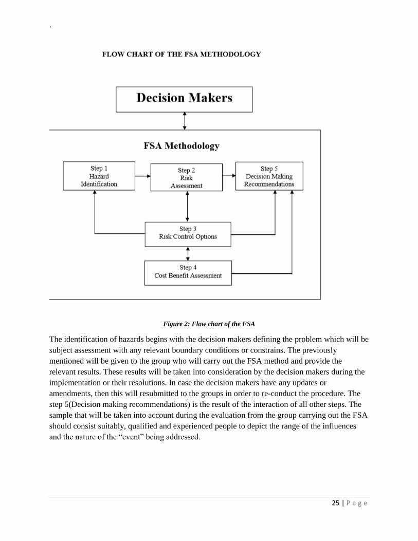
Figure 2: Flow chart of the FSA
The identification of hazards begins with the decision makers defining the problem which will be
subject assessment with any relevant boundary conditions or constrains. The previously
mentioned will be given to the group who will carry out the FSA method and provide the
relevant results. These results will be taken into consideration by the decision makers during the
implementation or their resolutions. In case the decision makers have any updates or
amendments, then this will resubmitted to the groups in order to re-conduct the procedure. The
step 5(Decision making recommendations) is the result of the interaction of all other steps. The
sample that will be taken into account during the evaluation from the group carrying out the FSA
should consist suitably, qualified and experienced people to depict the range of the influences
and the nature of the “event” being addressed.
`
26 | P a g e
The screening approach
The screening approach constitutes a thorough analysis procedure which aim into the
understanding of the nature and the significance of the problem. The analysis and the
implementation might be harder to manage in a case by case basis. In order to enable the FSA
and receive satisfactory results a preparation of a coarse qualitative analysis is recommended for
specific ship type per hazard category. In this respect the problem could be assesses in all
aspects. The characterization of hazards should be both qualitative and quantitative as well as
descriptive and mathematical.
A hierarchical, simple-analytic should be utilized in order to assist decision makers,
The information data
The consistency and suitability of data is essential in order to successfully carry out each step of
the FSA. Supporting material such as expert judgment, physical models, simulations and
analytical models may be used to achieve valuable results. Decision makers should first take into
consideration the existing available at IMO factors related to casualty and deficiency statistics.
Data such as,
1. Incident reports
2. Near misses and
3. Operational failures
Would be more affective during the decision.
The proactive scenarios considered as the most beneficial qualities of the FSA. The probabilistic
modeling and accident scenarios development can be used when the historical data are not
adequate during the process.
Decision makers should also bear in mind the changes occurred when intended to use the
aforementioned proactive scenarios.
Expert judgment
In order to receive satisfactory results from proactive methodology, the expert judgment from
decision makers is required. This also contributes in cases where the sample of historical data is
very small.
`
27 | P a g e
The expert judgment is the result of agreement of all expressed opinions. It is preferable to reach
a good level of agreement between the experts.24
24
IMO-Maritime safety committee, FORMAL SAFETY ASSESSMENT, “Consolidated text of the Guidelines for Formal Safety Assessment (FSA) for use in the IMO rule-making process (MSC/Circ.1023−MEPC/Circ.392)” May 2017, page 5, 6.
`
28 | P a g e
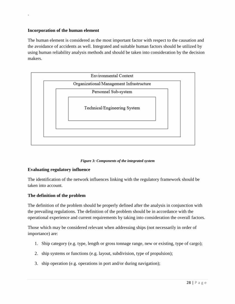
Incorporation of the human element
The human element is considered as the most important factor with respect to the causation and
the avoidance of accidents as well. Integrated and suitable human factors should be utilized by
using human reliability analysis methods and should be taken into consideration by the decision
makers.
Figure 3: Components of the integrated system
Evaluating regulatory influence
The identification of the network influences linking with the regulatory framework should be
taken into account.
The definition of the problem
The definition of the problem should be properly defined after the analysis in conjunction with
the prevailing regulations. The definition of the problem should be in accordance with the
operational experience and current requirements by taking into consideration the overall factors.
Those which may be considered relevant when addressing ships (not necessarily in order of
importance) are:
1. Ship category (e.g. type, length or gross tonnage range, new or existing, type of cargo);
2. ship systems or functions (e.g. layout, subdivision, type of propulsion);
3. ship operation (e.g. operations in port and/or during navigation);
`
29 | P a g e
4. external influences on the ship (e.g. Vessel Traffic System, weather forecasts, reporting,
routing);25
5. accident category (e.g. collision, explosion, fire);and
6. Risks associated with consequences such as injuries and/or fatalities to passengers and
crew, environmental impact, damage to the ship or port facilities, or commercial impact.
The factors of its problem should be reviewed individually though relative functions. For
instance, a problem related to the type of ship. Functions such as carriage of payload,
communication, emergency response, maneuverability, etc. are included. Alternatively, when the
problem is associated with a type of hazard, then functions such as prevention, detection, alarm,
containment, escape, suppression, etc. will be considered. Generic model functions, features,
characteristics and attributes that will be common to all ships or relevant to a problem in
question.
A holistic view, should be taken understanding the interaction between functions such as human
factor, organizational and management infrastructure, system maintenance which are all
governed and related to the physical laws of the outer environment. All systems are dynamically
interact by the others.
Results
The output of the problem definition comprises:
1. Problem definition and setting of boundaries; and
2. Development of a generic model.
FSA Step 1 - The identification of hazards
Step 1 comprises the identification of hazards related to scenarios which are prioritized by the
risk level to the problem under review. In order to achieve that the usage if HAZID technics are
required. These technics identify hazards which can contribute to an accident. With the screening
procedure in conjunction with the available data and expert judgement these hazards are
identifiable. The hazard identification should take into consideration functions and systems
generic related to specific ships type. Such methods are:
1. Identification of possible hazards: The approach used for the identification of hazards
is the combination of both creative and analytical technics. The creative technics ensure
that the process will be carried out in order to minimize the adherence only to the past
25
IMO-Maritime safety committee, FORMAL SAFETY ASSESSMENT, “Consolidated text of the Guidelines for Formal Safety Assessment (FSA) for use in the IMO rule-making process (MSC/Circ.1023−MEPC/Circ.392)” May 2017, page 6, 7, 8.
`
30 | P a g e
data. It is a process where a structured group review the causal factors of accident as well
as the relevant hazards. He group should take into account various aspects such as such as
ship design, operations and management and specialists to assist on the process. The
human element should be incorporated in all aspects all well.
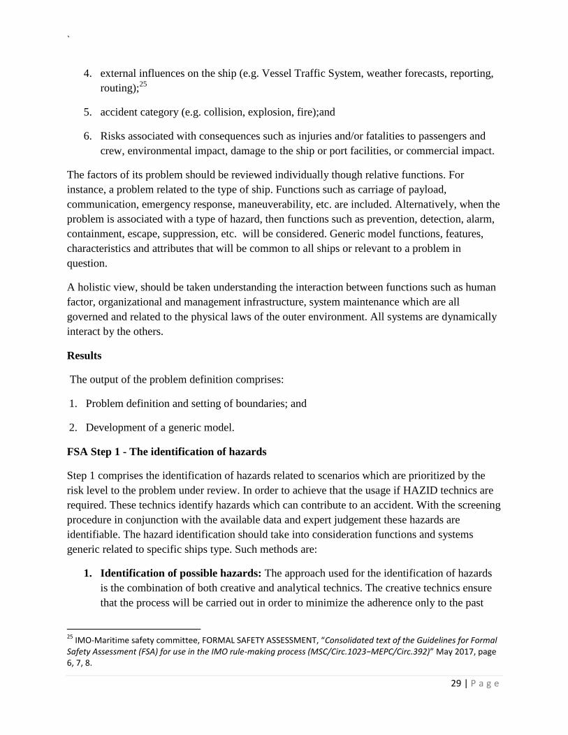
2. Ranking: In order to review the significance of each hazard related to the problem, all of
them should linked with a scenario. The frequency and the impact of each scenario is
subject to assessment. Ranking is prepared on the basis of the existing data supported by
relevant judgement on the scenarios. The combination of a frequency and a consequence
category represents a risk level.26
These level can be illustrated on a risk matrix as per
below,
Figure 4: Risk Matrix
27
Results
The output from step 1 comprises:
1. The hierarchy of hazards related to scenarios prioritize by risk level;
2. A description of the causes and effects.
26
IMO-Maritime safety committee, FORMAL SAFETY ASSESSMENT, “Consolidated text of the Guidelines for Formal Safety Assessment (FSA) for use in the IMO rule-making process (MSC/Circ.1023−MEPC/Circ.392)” May 2017, page 8, 9. 27
IMO-Maritime safety committee, FORMAL SAFETY ASSESSMENT, “Consolidated text of the Guidelines for Formal Safety Assessment (FSA) for use in the IMO rule-making process (MSC/Circ.1023−MEPC/Circ.392)” figure 4, May 2017, page 18.
`
31 | P a g e
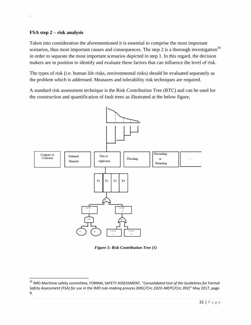
FSA step 2 – risk analysis
Taken into consideration the aforementioned it is essential to comprise the most important
scenarios, thus most important causes and consequences. The step 2 is a thorough investigation28
in order to separate the most important scenarios depicted in step 1. In this regard, the decision
makers are in position to identify and evaluate these factors that can influence the level of risk.
The types of risk (i.e. human life risks, environmental risks) should be evaluated separately as
the problem which is addressed. Measures and tolerability risk techniques are required.
A standard risk assessment technique is the Risk Contribution Tree (RTC) and can be used for
the construction and quantification of fault trees as illustrated at the below figure,
Figure 5: Risk Contribution Tree (1)
28
IMO-Maritime safety committee, FORMAL SAFETY ASSESSMENT, “Consolidated text of the Guidelines for Formal Safety Assessment (FSA) for use in the IMO rule-making process (MSC/Circ.1023−MEPC/Circ.392)” May 2017, page 9.
`
32 | P a g e
29
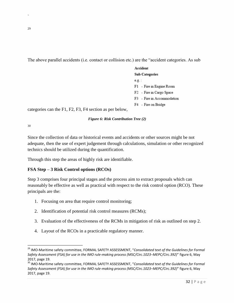
The above parallel accidents (i.e. contact or collision etc.) are the “accident categories. As sub
categories can the F1, F2, F3, F4 section as per below,
Figure 6: Risk Contribution Tree (2)
30
Since the collection of data or historical events and accidents or other sources might be not
adequate, then the use of expert judgement through calculations, simulation or other recognized
technics should be utilized during the quantification.
Through this step the areas of highly risk are identifiable.
FSA Step – 3 Risk Control options (RCOs)
Step 3 comprises four principal stages and the process aim to extract proposals which can
reasonably be effective as well as practical with respect to the risk control option (RCO). These
principals are the:
1. Focusing on area that require control monitoring;
2. Identification of potential risk control measures (RCMs);
3. Evaluation of the effectiveness of the RCMs in mitigation of risk as outlined on step 2.
4. Layout of the RCOs in a practicable regulatory manner.
29
IMO-Maritime safety committee, FORMAL SAFETY ASSESSMENT, “Consolidated text of the Guidelines for Formal Safety Assessment (FSA) for use in the IMO rule-making process (MSC/Circ.1023−MEPC/Circ.392)” figure 6, May 2017, page 19. 30
IMO-Maritime safety committee, FORMAL SAFETY ASSESSMENT, “Consolidated text of the Guidelines for Formal Safety Assessment (FSA) for use in the IMO rule-making process (MSC/Circ.1023−MEPC/Circ.392)” figure 6, May 2017, page 19.
`
33 | P a g e
Step 3 intending to create RCOs from the existing risks as well as from risks introduced by the
new technology and the organizational management. In this respect, a wide range of both
historical and newly identified risks (from steps 1 and 2) is achieved. This range should be taken
into consideration under techniques in a case by case basis.31
31
IMO-Maritime safety committee, FORMAL SAFETY ASSESSMENT, “Consolidated text of the Guidelines for Formal Safety Assessment (FSA) for use in the IMO rule-making process (MSC/Circ.1023−MEPC/Circ.392)” May 2017, page 10.
`
34 | P a g e
Methods
Determination of area requiring control.
The purpose of the 1st principal is to screen the output of step 2 in order to focus on the risks
areas requiring risk control. During the preparation of the assessment the following main aspects
will be under review:
1. Risk levels, the frequency of the occurrence as well as the severity of the outcome.
Accidents founded in unacceptable risk areas will be the primary target under review;
2. Probability, the reviewing of the risk that is most probable to occurred. This differs from
the severity of the outcome;
3. Severity, the analysis of areas that contribute to the highest severity outcome. These
differs from the probability of occurrence; and
4. Confidence, area where uncertainty prevails either or risk or probability. The uncertain
areas should be specific and separately addressed.
Identification of potential RCMs
The identification of potential RCMs carried out with structure review technics which cannot
identified with existing measures. The preparation of causal chains and risk attributes (I.e.
Mitigating risk control, involved human factors, Quantitative or Qualitative) might utilized
during the process.
The prime purpose of input risk attributes related to the attempt to build up a process which
understand the “behavior” of RCM. This also enhance guidance with other applicable risk
controls. Many risk requires events while causes can develop and diversify and can express as
follows:
Causal factors → failure → circumstance → accident → consequences
The RCMs should aim in general as follows:
1. Reduce the frequency of the event by actions of the management with respect to policies
and procedures, training;
2. Effect of failure reduction in order to prevent accidents;
3. Minimize these circumstance where failures might occurred;
4. Reduction of the consequence when an accident occurred.
`
35 | P a g e
The step 2 assists in risk reduction effectiveness taking into account any side effects.32
Composition of the RCOs
This stage will categorize the RCMs in a practicable manner, including a range of possible
approaches as well as the grouping of measures separately into options.
Below outlined two approaches associated with the likelihood and the escalation of the
occurrence:
1. “General approach”: Stabilization of the likelihood of occurrence of the event through
risk control. Controlling the initiation of accidents with other several preventing effects.
2. “Distributed approach”: which provided stabilization of the escalation of the incident
along with prevention of escalation from several different unrelated accident to the
initiate stages.
Groups of RCOs that may be affected by the combination of measures proposed should be
identified.
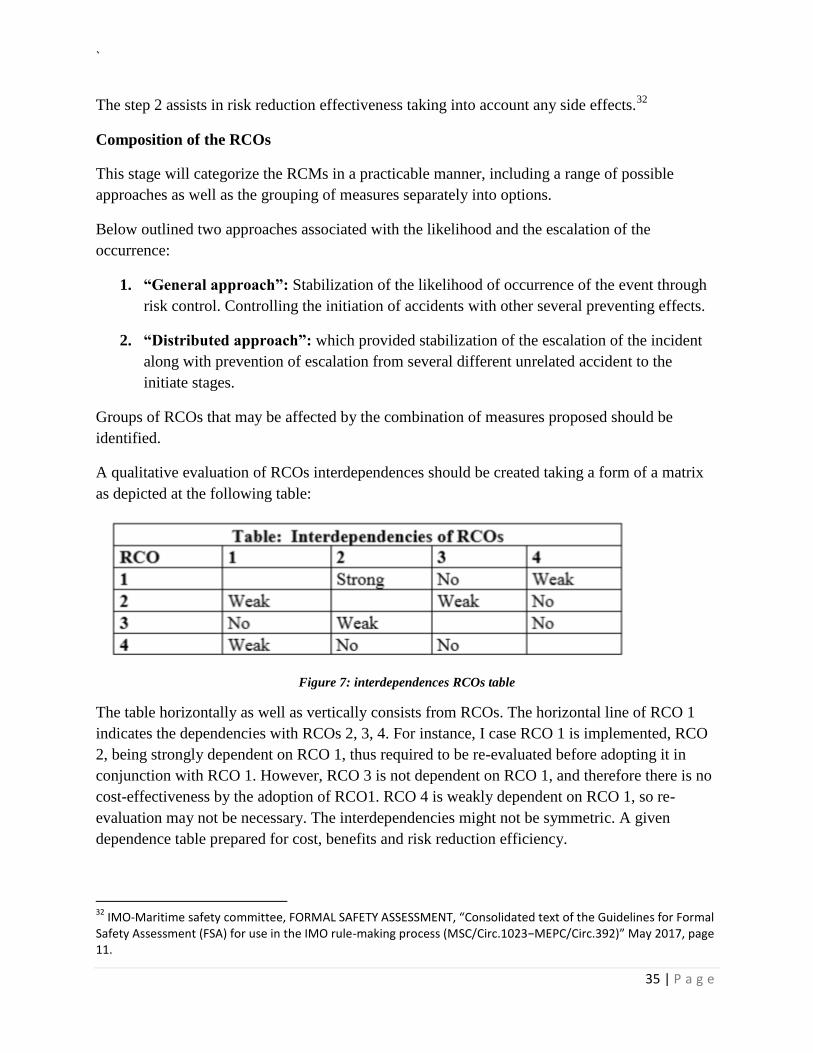
A qualitative evaluation of RCOs interdependences should be created taking a form of a matrix
as depicted at the following table:
Figure 7: interdependences RCOs table
The table horizontally as well as vertically consists from RCOs. The horizontal line of RCO 1
indicates the dependencies with RCOs 2, 3, 4. For instance, I case RCO 1 is implemented, RCO
2, being strongly dependent on RCO 1, thus required to be re-evaluated before adopting it in
conjunction with RCO 1. However, RCO 3 is not dependent on RCO 1, and therefore there is no
cost-effectiveness by the adoption of RCO1. RCO 4 is weakly dependent on RCO 1, so re-
evaluation may not be necessary. The interdependencies might not be symmetric. A given
dependence table prepared for cost, benefits and risk reduction efficiency.
32
IMO-Maritime safety committee, FORMAL SAFETY ASSESSMENT, “Consolidated text of the Guidelines for Formal Safety Assessment (FSA) for use in the IMO rule-making process (MSC/Circ.1023−MEPC/Circ.392)” May 2017, page 11.
`
36 | P a g e
Results
The output from step 3 comprises:
1. A range of the RCOs that are assessed with respect to their effectiveness in risk
mitigation;
2. A list of interested entities affected by the identified RCOs; and
3. Interdependencies between identified RCOs tables.
FSA Step 4 – Cost benefit assessment
The purpose of this step is to review the benefits and costs from the implementation of each
RCO outlined in step 3.
A cost benefit assessment might incorporate the Consideration of risks explained in step 1, both
in terms of frequency and consequence. In this regard, it can define the risk level of the
considered situation. Furthermore, comprises the arrangement of RCOs in a way that clarifies the
costs and benefit resulting from the implementation of an RCO33
. Thus, the cost and benefits of
all RCOs can be estimated. The estimation and comparison in terms of cost effectiveness of each
RCO is essential in order to calculate the cost per unit risk reduction reached as a result of
implementing the option. The cost-benefit hierarchy of the proposed RCOS in order to be
utilized as outcome – decision-making recommendations – in step 5 (e.g. to screen those which
are not cost effective or impractical).
33
IMO-Maritime safety committee, FORMAL SAFETY ASSESSMENT, “Consolidated text of the Guidelines for Formal Safety Assessment (FSA) for use in the IMO rule-making process (MSC/Circ.1023−MEPC/Circ.392)” May 2017, page 12.
`
37 | P a g e
Relevant costs should be considered on the basis of life cycle costs which might include initial,
operating, training, inspection, and certification, decommission etc. On the other hand, benefits
may include are reduction:
1. Fatalities;
2. Injuries;
3. Inspection;
4. Certification;
5. Decommission; etc.34
Methods
Definition of the interested entities
In order to evaluate the abovementioned costs and benefits various methods and techniques shall
be conducted for the overall situation. Furthermore, for those entities that considered as the most
influenced by the problem I question, a separate process should be initiated.
In general an interested entity can be denoted as the person organization, company, coastal State,
flag State, etc. who is directly or indirectly affected by an accident or by the cost effectiveness of
the proposed new regulation. The grouping of similar interests entities can as the purpose of the
FSA applying accordingly.
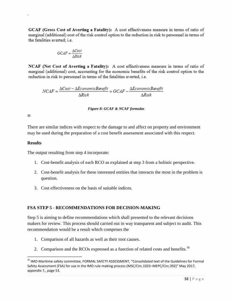
Calculations indices for cost effectiveness
Several indices may express cost effectiveness in relation to safety of life such as Gross Cost of
Averting a Fatality (Gross CAF) and Net Cost of Averting a Fatality (Net CAF). Below as
explained on appendix 7:
34
IMO-Maritime safety committee, FORMAL SAFETY ASSESSMENT, “Consolidated text of the Guidelines for Formal Safety Assessment (FSA) for use in the IMO rule-making process (MSC/Circ.1023−MEPC/Circ.392)” May 2017, page 12,13.
`
38 | P a g e
Figure 8: GCAF & NCAF formulas
35
There are similar indices with respect to the damage to and affect on property and environment
may be used during the preparation of a cost benefit assessment associated with this respect.
Results
The output resulting from step 4 incorporate:
1. Cost-benefit analysis of each RCO as explained at step 3 from a holistic perspective.
2. Cost-benefit analysis for these interested entities that interacts the most in the problem is
question.
3. Cost effectiveness on the basis of suitable indices.
FSA STEP 5 - RECOMMENDATIONS FOR DECISION-MAKING
Step 5 is aiming to define recommendations which shall presented to the relevant decisions
makers for review. This process should carried out in way transparent and subject to audit. This
recommendation would be a result which comprises the
1. Comparison of all hazards as well as their root causes.
2. Comparison and the RCOs expressed as a function of related costs and benefits.36
35
IMO-Maritime safety committee, FORMAL SAFETY ASSESSMENT, “Consolidated text of the Guidelines for Formal Safety Assessment (FSA) for use in the IMO rule-making process (MSC/Circ.1023−MEPC/Circ.392)” May 2017, appendix 7,, page 53.
`
39 | P a g e
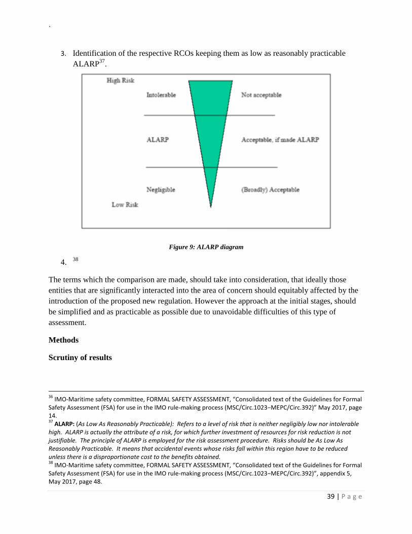
3. Identification of the respective RCOs keeping them as low as reasonably practicable
ALARP37
.
Figure 9: ALARP diagram
4. 38
The terms which the comparison are made, should take into consideration, that ideally those
entities that are significantly interacted into the area of concern should equitably affected by the
introduction of the proposed new regulation. However the approach at the initial stages, should
be simplified and as practicable as possible due to unavoidable difficulties of this type of
assessment.
Methods
Scrutiny of results
36
IMO-Maritime safety committee, FORMAL SAFETY ASSESSMENT, “Consolidated text of the Guidelines for Formal Safety Assessment (FSA) for use in the IMO rule-making process (MSC/Circ.1023−MEPC/Circ.392)” May 2017, page 14. 37
ALARP: (As Low As Reasonably Practicable): Refers to a level of risk that is neither negligibly low nor intolerable high. ALARP is actually the attribute of a risk, for which further investment of resources for risk reduction is not justifiable. The principle of ALARP is employed for the risk assessment procedure. Risks should be As Low As Reasonably Practicable. It means that accidental events whose risks fall within this region have to be reduced unless there is a disproportionate cost to the benefits obtained. 38
IMO-Maritime safety committee, FORMAL SAFETY ASSESSMENT, “Consolidated text of the Guidelines for Formal Safety Assessment (FSA) for use in the IMO rule-making process (MSC/Circ.1023−MEPC/Circ.392)”, appendix 5, May 2017, page 48.
`
40 | P a g e
The recommendations should be presented on the basis that can be understood by all parties
irrespectively of their experience in risk analysis and cost benefit related assessment and
technics. Those groups submitting the outcome of the FSA process should provide in due course
a relevant field where comments may incorporated.39
39
IMO-Maritime safety committee, FORMAL SAFETY ASSESSMENT, “Consolidated text of the Guidelines for Formal Safety Assessment (FSA) for use in the IMO rule-making process (MSC/Circ.1023−MEPC/Circ.392)” May 2017, page 14.
`
41 | P a g e
Risk evaluation Criteria
There are several standards for risk acceptance, none as yes has worldwide accepted.
Undoubtedly, those steps are mentioned within the FSA should be explicit.
Results
The output from step 5 comprises:
1. A tangible objective comparison of options aiming on providing a potential solution with
respect the risks and cost effectiveness in areas where legislation or rules should are
under review or development; and
2. Feedback that assists on reviewing the outcome from the previous steps.
Presentation of the FSA results
In order to present the results of the FSA results at the IMO, it I essential the common
understanding of the whole process with respect to the rule-making process. In this regard each
FSA process should:
1. Provide a clear statement in way transparent and subject to audit;
2. Hierarchy of hazards related to scenarios prioritize by risk level and the cost as well as
the benefits identified during the assessment;
3. Explain the assumptions, limitations, uncertainties, data models, methodologies and
inferences that utilized in order to resulting the assessment or the recommendations,
results of HAZID and risk analysis RCOs and outcomes on cost-benefit analysis that will
be taken under consideration during the decision making process;
4. Described the extent and magnitude of significant uncertainties related to the assessment
or the recommendations; and40
40
IMO-Maritime safety committee, FORMAL SAFETY ASSESSMENT, “Consolidated text of the Guidelines for Formal Safety Assessment (FSA) for use in the IMO rule-making process (MSC/Circ.1023−MEPC/Circ.392)” May 2017, page 14 and 15.
`
42 | P a g e
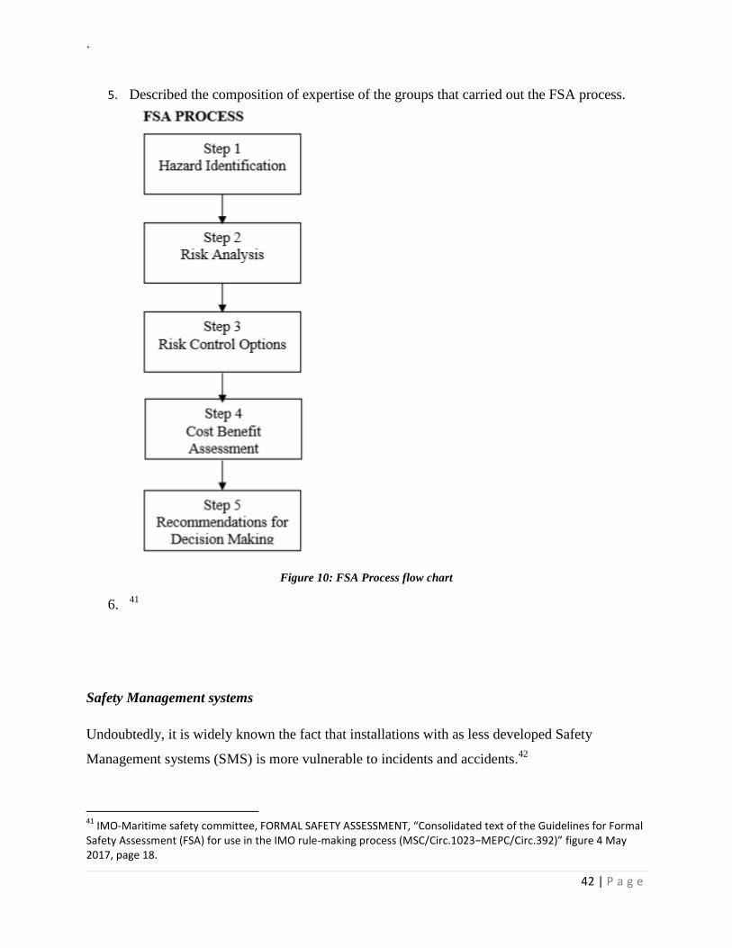
5. Described the composition of expertise of the groups that carried out the FSA process.
Figure 10: FSA Process flow chart
6. 41
Safety Management systems
Undoubtedly, it is widely known the fact that installations with as less developed Safety
Management systems (SMS) is more vulnerable to incidents and accidents.42
41
IMO-Maritime safety committee, FORMAL SAFETY ASSESSMENT, “Consolidated text of the Guidelines for Formal Safety Assessment (FSA) for use in the IMO rule-making process (MSC/Circ.1023−MEPC/Circ.392)” figure 4 May 2017, page 18.
`
43 | P a g e
In a management and organization view a comprehensive system with monitored procedures,
training, safety reviews and operations and maintenance procedures (record keeping) leads to
risk reduction and sometimes even impact reduction as well. In this respect attention is drawn
with respect to managerial and organization factors as counterbalance of many incidents,
accidents or maybe disasters, notably Piper Alpha.
The following considered as the main elements that should covered in the SMS and were
identified in the Cullen Report (Cullen 1990):
Organizational structure
Management personnel standards
Training for operations and emergencies
Safety assessment
Design procedures
Procedures for operations, maintenance, modifications and emergencies
Management of safety by contractors
The involvement of the workforce in safety
Accident and incident reporting, investigation and follow – up
Monitoring and auditing of the operation of the system
Systematic re-appraisal of the system in the light of the experience of the operator and
industry
There are several published guidelines towards good safety management practice, particularly in
the chemical and marine industries (e.g. HSE 1997b). Most of these are based or considered as
similar to the above-mentioned.
For offshore installations in UK waters, the Safety Case Regulations require the operator to have
adequate SMS in place and take into consideration that might be subject to audit by others. The
International Safety Management Code, adopted as part of the IMO Regulations on Safety of
Life at Sea (SOLAS) will establish common international requirements on the SMS for mobile
installations from 2002.
42
Det Norske Veritas - OFFSHORE TECHNOLOGY REPORT 2001/063, “Marine risk assessment”, Prepared by for the Health
and Safety Executive, 2002, page 51 - 52.
`
44 | P a g e
During the preparation of the risk assessments normally decision makers assume that an SMS is
in place that will ensure safety in a typical level of similar installations43
. However, some
attempts have been made to depict the actual SMS standards, as illustrated by audits of minor
incident experience, in the risk assessment of major accidents.
Risk assessment of transfer location
According to OCIMF latest STS guidelines it is suggested to prepared a risk assessment of
transfer location with included specific issues that need to be addressed as they often conducted
on areas that may be beyond the assistance of normal port services. Therefore, the outcome of
the risk assessment will lead to the development of operational procedures for subject STS Area.
The STS assessment should take into consideration and incorporated the following factors:
Local legislative requirements.
Exposure to, and/or shelter from, prevailing environmental conditions including, where
appropriate, metocean analysis.
Examine berthing and unearthing with respect to each STS type operation (Underway, at
anchor or alongside).
Examine transshipment with respect to each STS type operation (Underway, at anchor or
alongside).
Traffic monitoring of the location and any STS activities as well.
Spill and dispersion trajectories and environmental consequences.
Examine any other oil spillage response resources at the proposed STS location.
Availability and capability of support craft at the location.
Operational and resource integrity of any support elements provided by local
subcontractors on site.
Exposure of location to security threats.
Operational environmental limits, including abort criteria.
43
Det Norske Veritas - OFFSHORE TECHNOLOGY REPORT 2001/063, “Marine risk assessment”, Prepared for the Health
and Safety Executive, 2002, page 51.
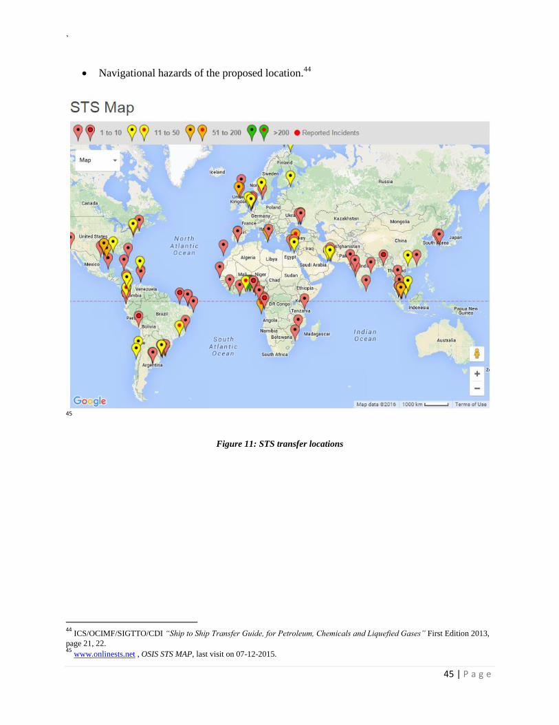
`
45 | P a g e
Navigational hazards of the proposed location.44
45
Figure 11: STS transfer locations
44
ICS/OCIMF/SIGTTO/CDI “Ship to Ship Transfer Guide, for Petroleum, Chemicals and Liquefied Gases” First Edition 2013,
page 21, 22. 45
www.onlinests.net , OSIS STS MAP, last visit on 07-12-2015.
`
46 | P a g e
Risk assessment of ship to ship operation
A risk assessment should be undertaken prior the commencement of the STS operation including
adequate information in order to ensure a good understanding and effective control of the
operation. The risk assessment should examine both physical and operational hazards as well as
define the sources by which they are managed, and should also illustrates the suitability of
equipment.
Risk assessment plays an important role as part of the pre-STS planning process and the
undermentioned depicts the minimum factors that should be considered during the preparation:
Ship compatibility, including mooring arrangements.
Suitability of the transfer location.
Properties of the cargo to be transferred.
Training, experience and qualifications of personnel.46
Suitable preparation of ships for the proposed operations and sufficient control during
operations.
Adequacy of navigational processes.
Adequate number of personnel assigned to control and perform the transfer operation.
Adequacy of communications between ships and/ or responsible persons.
Implications of differences in freeboard or the listing of ships when transferring cargo.
Equipment, including fenders and transfer hoses.
Anticipated environmental conditions.
Emergency planning and procedures.
The level of complexity will depend on the STS type of operation. Generic risk assessment
should be considered in case the planned operation conducted in a specific transfer area utilizing
standard approved STS equipment In this regard, attention is drawn during the addressing and
identification of hazards. In case the risk assessment is incorporated into a standard procedure,
46
ICS/OCIMF/SIGTTO/CDI “Ship to Ship Transfer Guide, for Petroleum, Chemicals and Liquefied Gases” First Edition 2013,
page 21, 22.
`
47 | P a g e
additional assessment should be undertaken for any deviation from the assumed or standard
conditions.47
In light of the complexity of liquefied petroleum gas (LPG) and liquefied natural gas (LNG) STS
transfer operations, it is important that the unique elements of each transfer are recognized and
that a full and thorough risk assessment is performed as part of the planning of each transfer.
The sources and consequences of risk should be addressed on the risk assessment. The risk
identification will vary according to the STS type of the operation. For instance, the risks related
with a double banking STS operation in which a vessel moored alongside will differ from the
risks associated with an underway or an at-anchor side-by-side STS procedure.
The risk assessment should take into account the risk mitigation measures as well as other factors
that might lead to changing of the probability/frequency of a risk event or its consequence.
Where administrative or procedural controls alone form the basis for risk reduction plans, these
procedures should be thoroughly evaluated.
On completion of the48
procedure, significant risks should have been identified and a suitable
risk management strategy developed for sake of additional risk reduction measures to an
acceptable level (ALARP).
47
ICS/OCIMF/SIGTTO/CDI “Ship to Ship Transfer Guide, for Petroleum, Chemicals and Liquefied Gases” First Edition 2013,
page 21, 22. 48
ICS/OCIMF/SIGTTO/CDI “Ship to Ship Transfer Guide, for Petroleum, Chemicals and Liquefied Gases” First Edition 2013,
page 22, 23.
`
48 | P a g e
The “Due Diligence” concept
The initialization of implementing the due diligence concept is definitely a complex procedure.
Undoubtedly involves a series of modifications as well as harmonization with the corporate SMS
and the strategy of the company. Decision-makers should utilize the appropriate tools for sake of
efficiency, cost controlling and risk reduction.
STS operations are normally characterized by specific commercial interests and same leads to
inevitable time constrains. In this respect, it lies in the tankers operators hands the responsibility
to develop procedures that vet all the third party companies, while keeping the associate logistics
at a practical and effective level for parties. These third parties in STS operations involved the
participating vessel, Service Providers, POACs as well as local national administrations.
The first step towards safety is to ensure, prior the initiation of any action, that all participating
parties are able and willing to follow all required and recommended safety rules. Since the
responsibility cannot forwarded by any means to a subcontractor or other participants, technical
operators to the best of their knowledge should always perform a thorough check with respect to
the qualification and credibility of the participants. The abovementioned concept is known as
due diligence as described at S. Perissakis et al (2010). The audits or vetting from industry
organizations such as Port State Controls or the Coast Guard, flag administrations and other
recognized organizations are considered as a tangible proof why ship owners should be bound
with the due diligence concept.
Demonstrating due diligence does not pushing towards implementation of a risk assessment in
every individual case. For instance, the evaluation and assess of the credibility of the partner
involved seems more efficient and less time-consuming than to assess the risks for tasks that
assigned to partner or affiliate companies. This practice seems that fulfils the requirements of a
successful and integrated due diligence concept in the decision-making process, while
simultaneously does not affect the budget cost of the operation and this is significant. Therefore,
in project management view the cost is stable, the quality is optimizing due to risk reduction and
the time is managed better and these leads to a successful operation.49
49
A. Glykas, S. Perissakis, “A risk assessment methodology as a tool for screening of Ship-to-Ship (STS) transfer operations.”
ECONSHIP 2011, Chios, Greece.
`
49 | P a g e
Vessel screening
During an STS operation, the chartered vessel will be moored alongside another participating
vessel. This procedures renders both ships performing as one whole operational entity and this
leads to vessel interaction and make both vessels vulnerable to each other. The nominated STS
vessel should be screened in order to ensure that she is suitable and safe for an STS operation
with the chartered vessel.
As referred in various Charter Parties the charterer agrees that the liability of the safe conduct of
the operation lies on Master hands who ensure that safety does not jeopardized by actions of
others. As stated at ExxonMobil Voy 2000 at paragraph (c) “..It is understood and agreed
however, that the master and Owner shall be fully and solely responsible for the operation,
management and navigation of Vessel during the entire loading, lightering and/ or discharging
operation.”
Therefore, the ship owner should exercise his due diligence when charterer nominates the
participating vessel and requests for owner’s acceptance. Below depicted the follow
actions/information that it is recommend from the Technical Operators to request from the
Managers of the nominated vessel:
Confirmation that the nominated STS vessel has P&I cover in place via a recognized P&I
Club.
Confirmation that the nominated STS vessel is in class with a recognized classification
society.
A completed list of the particulars of the nominated STS vessel should be available.
Latest SIRE inspection report date.
Vessel's historical Port State Control (PSC) records.
Confirmation that suitable security arrangements are in place on the participating STS
vessel and that she has an approved security plan onboard.
Declaration that a risk assessment has been undertaken prior to each STS operation.
The screening process should be performed by the ship, or alternatively by the company or a
specialized screening company. EQUASIS (http://www.equasis.org) is a recognized source for
obtaining information with respect to the classification society and the Port State Control (PSC)
`
50 | P a g e
50records or the MoUs. Finally, Vessel Particular form (VPQ or Questionnaire 88) form can be
considered as a complete list incorporating the necessary ships particulars.
Vessels compatibility for STS operations
After screening process, a vessel compatibility check should always be performed. The vessel
which is going to have STS operation with the chartered vessel, should not have any part of the
ship projected from the maximum breadth. Furthermore, the following issues should also be
examined for incompatibilities:
Mooring arrangement,
Manifold arrangement
Cargo Hoses Cranes
STS service provider screening/Assessment
The STS Service providers are responsible for providing with the appropriate equipment as well
as with guidance with respect to other critical decisions. The service provider is responsible for
the preparation of the mooring plan with the assistance of the involved ships as well as to appoint
an experienced POAC to superintend and advise Master(s) during the operation. However is
notable the fact that the Master(s) are always responsible for the safety of his/their vessel, thus in
case consider reasonably that safety is jeopardized has the overriding authority to abort or
cancelled the operation. In this regard, a screening process of the STS service provider is
required as well. During the process subject service provider will examine with respect to the
number of past STS operations and the performance records where possible unfavorable notes
should be taken into account. However, in screening of the entity terms the following key points
shall determine the credibility of the STS Service provider:
Certificate of incorporation
Certificate of insurance
Accreditation from local authorities
Quality management policy
50
A. Glykas, S. Perissakis, “A risk assessment methodology as a tool for screening of Ship-to-Ship (STS) transfer operations.”
ECONSHIP 2011, Chios, Greece.
`
51 | P a g e
Environmental protection management policy
Environmental protection management policy
The maintenance policy of the STS provided equipment51
51
A. Glykas, S. Perissakis, “A risk assessment methodology as a tool for screening of Ship-to-Ship (STS) transfer operations.”
ECONSHIP 2011, Chios, Greece.
`
52 | P a g e
The STS Equipment
Fenders used for Lightering Operations
In recent years, offshore STS transfer of crude oil has been increasing. Such operations is also
expanding to offshore LPG-transfer and to offshore LNG-terminal projects. An oil spill might
has severe impact on the environment and marine life, and accidental bursting of sub-standard
fenders can also lead to injure of personnel, crew and ship damages. Therefore oil companies,
shipping companies and manufacturers began to investigate recent accidents involving fenders to
try to prevent such occurrences. It was determined that variations of the originally designed
floating pneumatic fender with lower endurable pressure and/or the use of inferior materials had
been introduced into the market. In 1997, to prevent any further decline in the quality and
performance of floating pneumatic fenders, all parties concerned started working together to
create an international standard (ISO) to specify material, performance and dimensions of
floating fenders to keep berthing operations safe. The standard has been published as ISO17357,
First Edition on November 15, 2002, prepared by technical committee, ISO/TC 8 (ISO17357;
2002).52
The fenders that utilized in Ship-to-Ship transfer operations are divided into two categories,
primary and secondary fenders.53
52
The Yokohama Rubber CO.LTD., “Yokohama floating fenders Pneumatic 50&80”, Catalog No AF/CAT /2006/0, page 2. 53
ICS/OCIMF/SIGTTO/CDI “Ship to Ship Transfer Guide, for Petroleum, Chemicals and Liquefied Gases” First Edition 2013,
page 71.
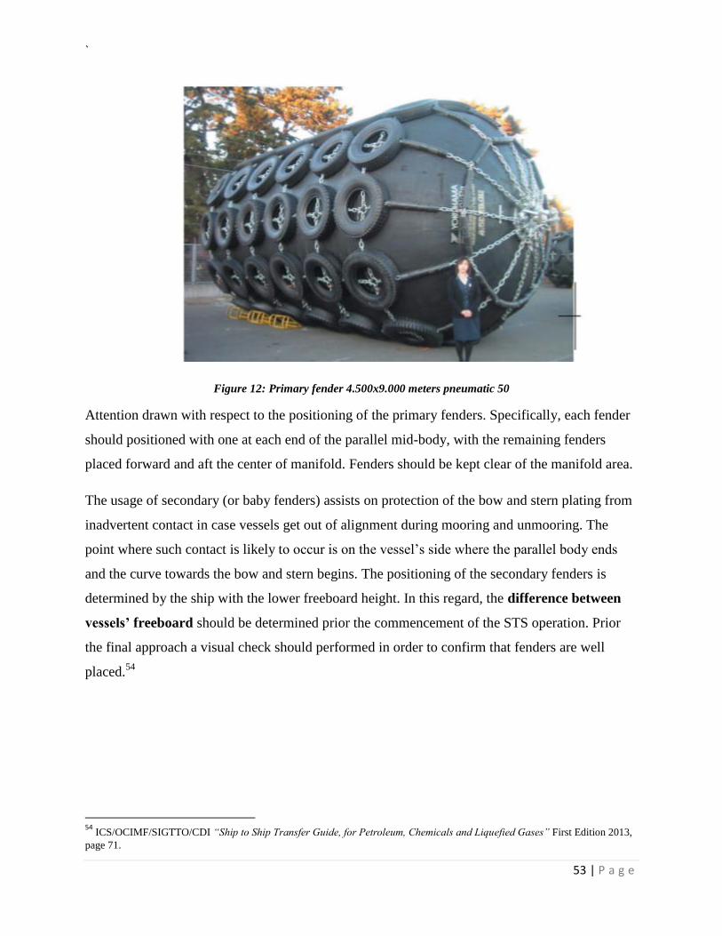
`
53 | P a g e
Figure 12: Primary fender 4.500x9.000 meters pneumatic 50
Attention drawn with respect to the positioning of the primary fenders. Specifically, each fender
should positioned with one at each end of the parallel mid-body, with the remaining fenders
placed forward and aft the center of manifold. Fenders should be kept clear of the manifold area.
The usage of secondary (or baby fenders) assists on protection of the bow and stern plating from
inadvertent contact in case vessels get out of alignment during mooring and unmooring. The
point where such contact is likely to occur is on the vessel’s side where the parallel body ends
and the curve towards the bow and stern begins. The positioning of the secondary fenders is
determined by the ship with the lower freeboard height. In this regard, the difference between
vessels’ freeboard should be determined prior the commencement of the STS operation. Prior
the final approach a visual check should performed in order to confirm that fenders are well
placed.54
54
ICS/OCIMF/SIGTTO/CDI “Ship to Ship Transfer Guide, for Petroleum, Chemicals and Liquefied Gases” First Edition 2013,
page 71.
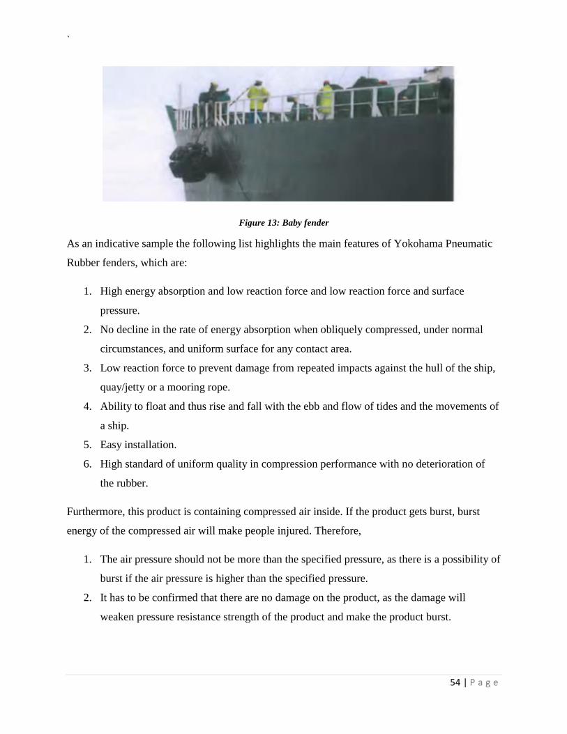
`
54 | P a g e
Figure 13: Baby fender
As an indicative sample the following list highlights the main features of Yokohama Pneumatic
Rubber fenders, which are:
1. High energy absorption and low reaction force and low reaction force and surface
pressure.
2. No decline in the rate of energy absorption when obliquely compressed, under normal
circumstances, and uniform surface for any contact area.
3. Low reaction force to prevent damage from repeated impacts against the hull of the ship,
quay/jetty or a mooring rope.
4. Ability to float and thus rise and fall with the ebb and flow of tides and the movements of
a ship.
5. Easy installation.
6. High standard of uniform quality in compression performance with no deterioration of
the rubber.
Furthermore, this product is containing compressed air inside. If the product gets burst, burst
energy of the compressed air will make people injured. Therefore,
1. The air pressure should not be more than the specified pressure, as there is a possibility of
burst if the air pressure is higher than the specified pressure.
2. It has to be confirmed that there are no damage on the product, as the damage will
weaken pressure resistance strength of the product and make the product burst.
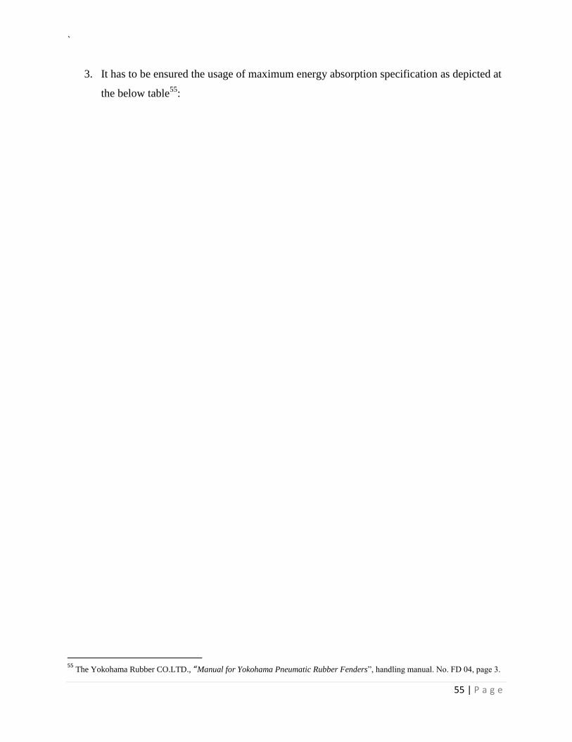
`
55 | P a g e
3. It has to be ensured the usage of maximum energy absorption specification as depicted at
the below table55
:
55
The Yokohama Rubber CO.LTD., “Manual for Yokohama Pneumatic Rubber Fenders”, handling manual. No. FD 04, page 3.
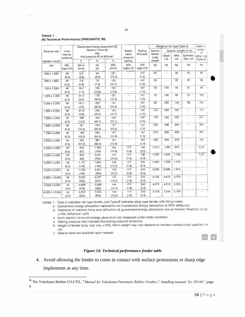
`
56 | P a g e
56
Figure 14: Technical performance fender table
4. Avoid allowing the fender to come in contact with surface protrusions or sharp edge
implements at any time.
56
The Yokohama Rubber CO.LTD., “Manual for Yokohama Pneumatic Rubber Fenders”, handling manual. No. FD 04”, page
4.
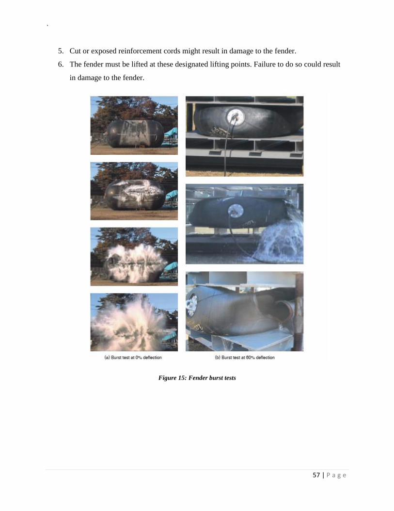
`
57 | P a g e
5. Cut or exposed reinforcement cords might result in damage to the fender.
6. The fender must be lifted at these designated lifting points. Failure to do so could result
in damage to the fender.
Figure 15: Fender burst tests
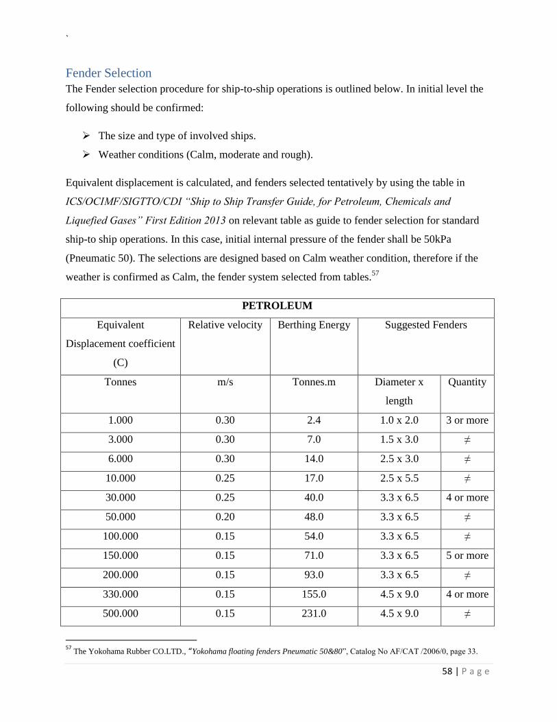
`
58 | P a g e
Fender Selection
The Fender selection procedure for ship-to-ship operations is outlined below. In initial level the
following should be confirmed:
The size and type of involved ships.
Weather conditions (Calm, moderate and rough).
Equivalent displacement is calculated, and fenders selected tentatively by using the table in
ICS/OCIMF/SIGTTO/CDI “Ship to Ship Transfer Guide, for Petroleum, Chemicals and
Liquefied Gases” First Edition 2013 on relevant table as guide to fender selection for standard
ship-to ship operations. In this case, initial internal pressure of the fender shall be 50kPa
(Pneumatic 50). The selections are designed based on Calm weather condition, therefore if the
weather is confirmed as Calm, the fender system selected from tables.57
PETROLEUM
Equivalent
Displacement coefficient
(C)
Relative velocity Berthing Energy Suggested Fenders
Tonnes m/s Tonnes.m Diameter x
length
Quantity
1.000 0.30 2.4 1.0 x 2.0 3 or more
3.000 0.30 7.0 1.5 x 3.0 ≠
6.000 0.30 14.0 2.5 x 3.0 ≠
10.000 0.25 17.0 2.5 x 5.5 ≠
30.000 0.25 40.0 3.3 x 6.5 4 or more
50.000 0.20 48.0 3.3 x 6.5 ≠
100.000 0.15 54.0 3.3 x 6.5 ≠
150.000 0.15 71.0 3.3 x 6.5 5 or more
200.000 0.15 93.0 3.3 x 6.5 ≠
330.000 0.15 155.0 4.5 x 9.0 4 or more
500.000 0.15 231.0 4.5 x 9.0 ≠
57
The Yokohama Rubber CO.LTD., “Yokohama floating fenders Pneumatic 50&80”, Catalog No AF/CAT /2006/0, page 33.
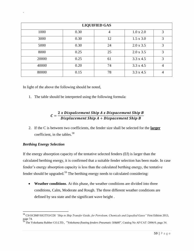
`
59 | P a g e
LIQUIFIED GAS
1000 0.30 4 1.0 x 2.0 3
3000 0.30 12 1.5 x 3.0 3
5000 0.30 24 2.0 x 3.5 3
8000 0.25 25 2.0 x 3.5 3
20000 0.25 61 3.3 x 4.5 3
40000 0.20 74 3.3 x 4.5 4
80000 0.15 78 3.3 x 4.5 4
In light of the above the following should be noted,
1. The table should be interpreted using the following formula:
𝑪 =𝟐 𝒙 𝑫𝒊𝒔𝒑𝒂𝒍𝒄𝒆𝒎𝒆𝒏𝒕 𝑺𝒉𝒊𝒑 𝑨 𝒙 𝑫𝒊𝒔𝒑𝒂𝒄𝒆𝒎𝒆𝒏𝒕 𝑺𝒉𝒊𝒑 𝑩
𝑫𝒊𝒔𝒑𝒍𝒂𝒄𝒆𝒎𝒆𝒏𝒕 𝑺𝒉𝒊𝒑 𝑨 + 𝑫𝒊𝒔𝒑𝒂𝒄𝒆𝒎𝒆𝒏𝒕 𝑺𝒉𝒊𝒑 𝑩
2. If the C is between two coefficients, the fender size shall be selected for the larger
coefficient, in the tables.58
Berthing Energy Selection
If the energy absorption capacity of the tentative selected fenders (Ef) is larger than the
calculated berthing energy, it is confirmed that a suitable fender selection has been made. In case
fender’s energy absorption capacity is less than the calculated berthing energy, the tentative
fender should be upgraded.59
The berthing energy needs to calculated considering:
Weather conditions. At this phase, the weather conditions are divided into three
conditions, Calm, Moderate and Rough. The three different weather conditions are
defined by sea state and the significant wave height .
58
CS/OCIMF/SIGTTO/CDI “Ship to Ship Transfer Guide, for Petroleum, Chemicals and Liquefied Gases” First Edition 2013,
page 74. 59
The Yokohama Rubber CO.LTD., “Yokohama floating fenders Pneumatic 50&80”, Catalog No AF/CAT /2006/0, page 34.
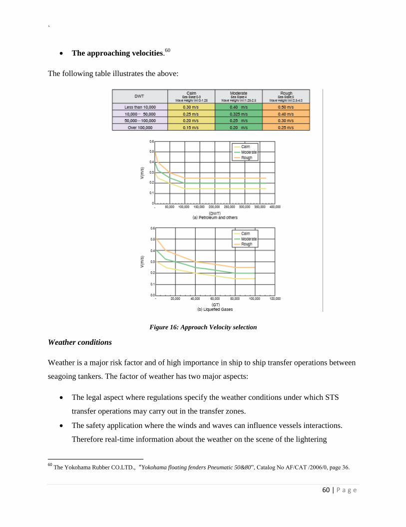
`
60 | P a g e
The approaching velocities.60
The following table illustrates the above:
Figure 16: Approach Velocity selection
Weather conditions
Weather is a major risk factor and of high importance in ship to ship transfer operations between
seagoing tankers. The factor of weather has two major aspects:
The legal aspect where regulations specify the weather conditions under which STS
transfer operations may carry out in the transfer zones.
The safety application where the winds and waves can influence vessels interactions.
Therefore real-time information about the weather on the scene of the lightering
60
The Yokohama Rubber CO.LTD., “Yokohama floating fenders Pneumatic 50&80”, Catalog No AF/CAT /2006/0, page 36.
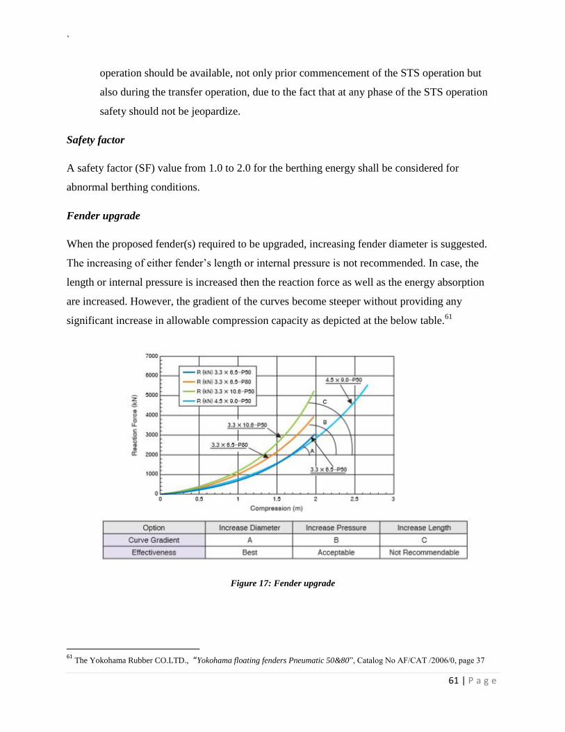
`
61 | P a g e
operation should be available, not only prior commencement of the STS operation but
also during the transfer operation, due to the fact that at any phase of the STS operation
safety should not be jeopardize.
Safety factor
A safety factor (SF) value from 1.0 to 2.0 for the berthing energy shall be considered for
abnormal berthing conditions.
Fender upgrade
When the proposed fender(s) required to be upgraded, increasing fender diameter is suggested.
The increasing of either fender’s length or internal pressure is not recommended. In case, the
length or internal pressure is increased then the reaction force as well as the energy absorption
are increased. However, the gradient of the curves become steeper without providing any
significant increase in allowable compression capacity as depicted at the below table.61
Figure 17: Fender upgrade
61
The Yokohama Rubber CO.LTD., “Yokohama floating fenders Pneumatic 50&80”, Catalog No AF/CAT /2006/0, page 37
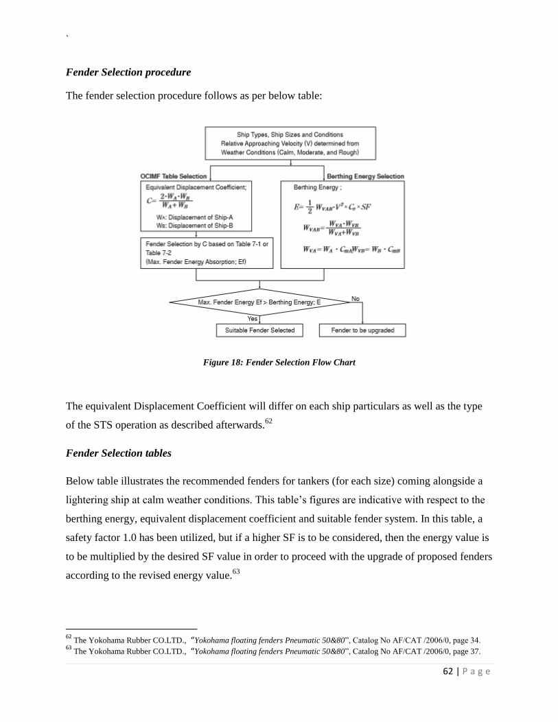
`
62 | P a g e
Fender Selection procedure
The fender selection procedure follows as per below table:
Figure 18: Fender Selection Flow Chart
The equivalent Displacement Coefficient will differ on each ship particulars as well as the type
of the STS operation as described afterwards.62
Fender Selection tables
Below table illustrates the recommended fenders for tankers (for each size) coming alongside a
lightering ship at calm weather conditions. This table’s figures are indicative with respect to the
berthing energy, equivalent displacement coefficient and suitable fender system. In this table, a
safety factor 1.0 has been utilized, but if a higher SF is to be considered, then the energy value is
to be multiplied by the desired SF value in order to proceed with the upgrade of proposed fenders
according to the revised energy value.63
62
The Yokohama Rubber CO.LTD., “Yokohama floating fenders Pneumatic 50&80”, Catalog No AF/CAT /2006/0, page 34. 63
The Yokohama Rubber CO.LTD., “Yokohama floating fenders Pneumatic 50&80”, Catalog No AF/CAT /2006/0, page 37.
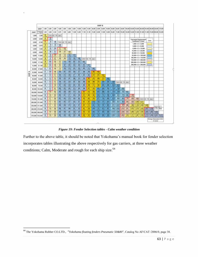
`
63 | P a g e
Figure 19: Fender Selection tables - Calm weather condition
Further to the above table, it should be noted that Yokohama’s manual book for fender selection
incorporates tables illustrating the above respectively for gas carriers, at three weather
conditions; Calm, Moderate and rough for each ship size.64
64
The Yokohama Rubber CO.LTD., “Yokohama floating fenders Pneumatic 50&80”, Catalog No AF/CAT /2006/0, page 38.
`
64 | P a g e
The STS Hoses
The purpose of the cargo hoses is to transfer the oil cargo quantity from the STB (ship to be lightered) to
the receiving ship. In this regard, these hoses should be suitable, thus designated and constructed in a
way that could accommodate the specific product to be transferred. It is notable that there is no
international standard for a hose that will be utilized in a STS transfer operation. The docks industry
standards often have been used for assessment purposes. These standards include EN7 765 for oil
service65, EN7 3765 for oils, solvents and chemicals66, ISO 70380, ISO 2928 and EN 73766 for liquefied
petroleum gas (LPG)676869, EN 7474-2 for LNG70, and EN ISO 8330 and EN ISO 803 7 for rubber and
plastics hoses and hose assemblies7172.
65
EN 1765 Rubber Hose Assemblies for Oil Suction and Discharge Services, 2004 66
EN 13765 Thermoplastic MUlti-layer (Non-vulcanized) Hoses and Hose Assemblies for the Transfer of Hydrocarbons, Solvents and Chemicals, 2010 67
ISO 10380 Corrugated Metal Hoses and Hose Assemblies, 2003 68
ISO 2928 Rubber Hoses and Hose Assemblies for Liquefied Petroleum Gas (LPG) in the Liquid or Gaseous Phase and Natural Gas up to 25 bar (2.5 MPa), 2003 69
EN 13766 Thermoplastic MUlti-layer (Non-vulcanised) Hoses and Hose Assemblies for the Transfer of Liquid Petroleum Gas and Liquefied Natural Gas, 2010 70
EN 1474-2 Installation and Equipment for Liquefied Natural Gas - Design and Testing of Marine Transfer Systems, Part 2: Design and Testing ofTransfer Hoses, 2008 71
EN ISO 8330:2008 Rubber and Plastics Hoses and Hose Assemblies -Vocabulary 72
EN ISO 8031 :2009 Rubber and Plastics Hoses and Hose Assemblies - Determination of Electrical Resistance and Conductivity
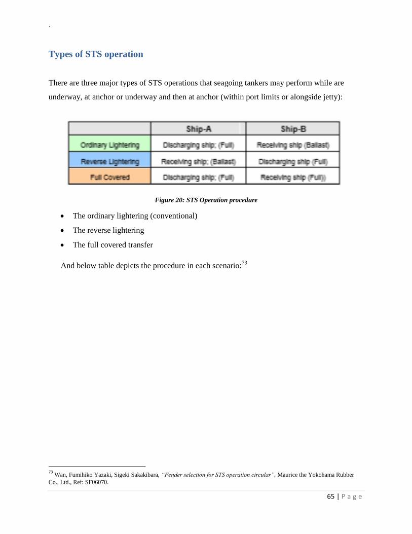
`
65 | P a g e
Types of STS operation
There are three major types of STS operations that seagoing tankers may perform while are
underway, at anchor or underway and then at anchor (within port limits or alongside jetty):
Figure 20: STS Operation procedure
The ordinary lightering (conventional)
The reverse lightering
The full covered transfer
And below table depicts the procedure in each scenario:73
73
Wan, Fumihiko Yazaki, Sigeki Sakakibara, “Fender selection for STS operation circular”, Maurice the Yokohama Rubber
Co., Ltd., Ref: SF06070.
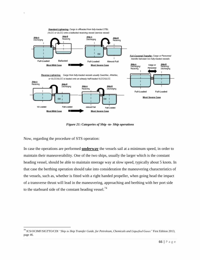
`
66 | P a g e
Figure 21: Categories of Ship -to- Ship operations
Now, regarding the procedure of STS operation:
In case the operations are performed underway the vessels sail at a minimum speed, in order to
maintain their maneuverability. One of the two ships, usually the larger which is the constant
heading vessel, should be able to maintain steerage way at slow speed, typically about 5 knots. In
that case the berthing operation should take into consideration the maneuvering characteristics of
the vessels, such as, whether is fitted with a right handed propeller, when going head the impact
of a transverse thrust will lead in the maneuvering, approaching and berthing with her port side
to the starboard side of the constant heading vessel.74
74
ICS/OCIMF/SIGTTO/CDI “Ship to Ship Transfer Guide, for Petroleum, Chemicals and Liquefied Gases” First Edition 2013,
page 46.
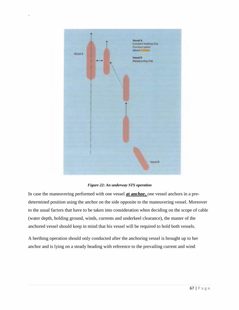
`
67 | P a g e
Figure 22: An underway STS operation
In case the maneuvering performed with one vessel at anchor, one vessel anchors in a pre-
determined position using the anchor on the side opposite to the maneuvering vessel. Moreover
to the usual factors that have to be taken into consideration when deciding on the scope of cable
(water depth, holding ground, winds, currents and underkeel clearance), the master of the
anchored vessel should keep in mind that his vessel will be required to hold both vessels.
A berthing operation should only conducted after the anchoring vessel is brought up to her
anchor and is lying on a steady heading with reference to the prevailing current and wind
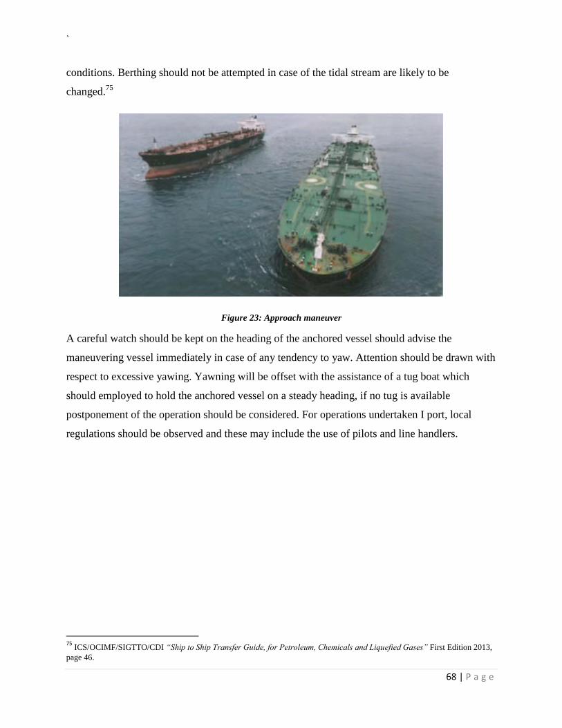
`
68 | P a g e
conditions. Berthing should not be attempted in case of the tidal stream are likely to be
changed.75
Figure 23: Approach maneuver
A careful watch should be kept on the heading of the anchored vessel should advise the
maneuvering vessel immediately in case of any tendency to yaw. Attention should be drawn with
respect to excessive yawing. Yawning will be offset with the assistance of a tug boat which
should employed to hold the anchored vessel on a steady heading, if no tug is available
postponement of the operation should be considered. For operations undertaken I port, local
regulations should be observed and these may include the use of pilots and line handlers.
75
ICS/OCIMF/SIGTTO/CDI “Ship to Ship Transfer Guide, for Petroleum, Chemicals and Liquefied Gases” First Edition 2013,
page 46.
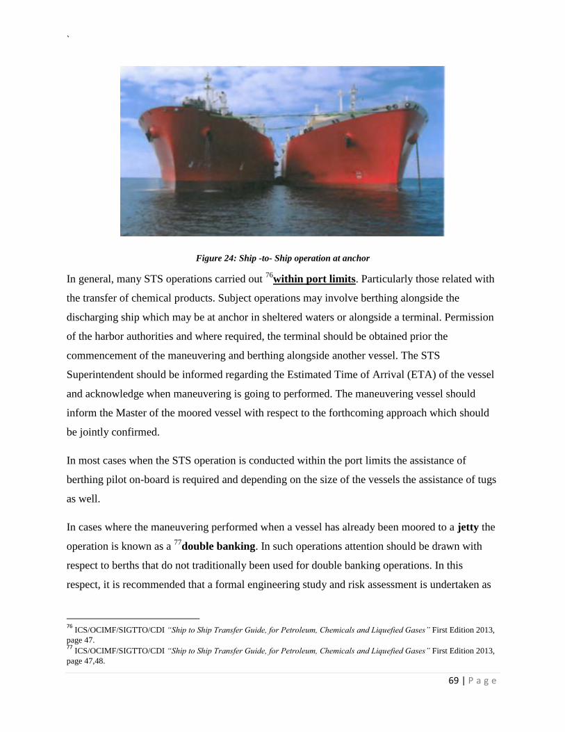
`
69 | P a g e
Figure 24: Ship -to- Ship operation at anchor
In general, many STS operations carried out 76
within port limits. Particularly those related with
the transfer of chemical products. Subject operations may involve berthing alongside the
discharging ship which may be at anchor in sheltered waters or alongside a terminal. Permission
of the harbor authorities and where required, the terminal should be obtained prior the
commencement of the maneuvering and berthing alongside another vessel. The STS
Superintendent should be informed regarding the Estimated Time of Arrival (ETA) of the vessel
and acknowledge when maneuvering is going to performed. The maneuvering vessel should
inform the Master of the moored vessel with respect to the forthcoming approach which should
be jointly confirmed.
In most cases when the STS operation is conducted within the port limits the assistance of
berthing pilot on-board is required and depending on the size of the vessels the assistance of tugs
as well.
In cases where the maneuvering performed when a vessel has already been moored to a jetty the
operation is known as a 77
double banking. In such operations attention should be drawn with
respect to berths that do not traditionally been used for double banking operations. In this
respect, it is recommended that a formal engineering study and risk assessment is undertaken as
76
ICS/OCIMF/SIGTTO/CDI “Ship to Ship Transfer Guide, for Petroleum, Chemicals and Liquefied Gases” First Edition 2013,
page 47. 77
ICS/OCIMF/SIGTTO/CDI “Ship to Ship Transfer Guide, for Petroleum, Chemicals and Liquefied Gases” First Edition 2013,
page 47,48.
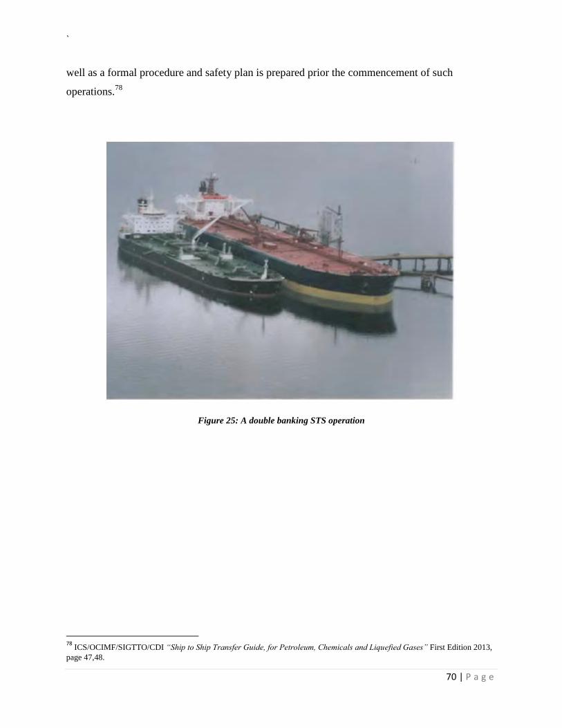
`
70 | P a g e
well as a formal procedure and safety plan is prepared prior the commencement of such
operations.78
Figure 25: A double banking STS operation
78
ICS/OCIMF/SIGTTO/CDI “Ship to Ship Transfer Guide, for Petroleum, Chemicals and Liquefied Gases” First Edition 2013,
page 47,48.
`
71 | P a g e
The legal framework in STS operations
The resolution IMO MEPC 186(59)
The adoption of resolution IMO MEPC 186(59) led to the establishment of a regulatory
framework in STS operations. As per proposed amendments by the MEPC, STS operation are
now being regulated, thus from 01/01/2011 and as deadline the 01-04-2012 the existence of an
STS plan with the adapted policies and industry guidelines will became obligatory. In this
regard, STS operations will be part of a sound Management and will be incorporated in Tanker
operators SMS. For sake of safety, technical managers are obliged to prove that the due diligence
concept is being implemented and the risk reduction is first priority when an STS operation
during the preparation of an STS operation and performance of an STS operation. The safety in
STS operation is now associated with “casting off” liabilities whenever an accident occurred and
leads to environmental consequences.
The need of safety culture dissemination as well as the proof that all parties demonstrate wise
and sound management led the adoption of regulations that includes 48-hour notification, record
keeping procedures for three years and the introduction of a qualified POAC. Therefore, Tanker
operators should be able to prove that operates in terms of wise and sound management during
STS transfer operations and this should be illustrated during a vetting procedure from an Oil
major. In light of the above, and from Ship-owners side the creation of an STS plan is obligatory.
Thus, simultaneously with the main STS Guidelines and procedures the STS plan incorporates
the following procedures:
1. Procedures for STS Equipment storage and maintenance according to standards, in case a
charterer decides to permanently supply a vessel with fenders and hoses.
2. Information resources on preparedness and response to oil spills.
3. Private response organizations worldwide.
4. Safety and Emergency preparedness procedures.
5. CFR USA regulations for lightering operations.
6. Due diligence procedures for evaluation performance of the STS Operators.
The STS Plan procedures and adopted policies became mandatory from the first annual survey of
vessels, in the wake of adoption of 1st January 2011. In this re regard, STS operations became
officially part of the normal procedures in the SMS (safety management system).
`
72 | P a g e
As a result of the above, from the one side, ships (Masters) have the responsibility to ensure that
safety would not be compromised and from the other side, Technical Operators should exercise
properly their due diligence with “tangible” proofs.
The involved vessels as depicted at regulation 41.3 of the resolution, shall comply with its STS
operations Plan. However the regulation prescribes specific cases where the STS plan does not
apply. The STS operation plan does not apply:
1. To bunkering operations as per regulation 40.3. The STS plan applies only to cargo
transshipment.
2. To floating production, storage and offloading facilities (FPSOs) used for the offshore
production and storage of oil and floating storage units (FSUs) used for the offshore
storage of produced oil.
3. To transfer operations which related with fixed or floating oil platforms including drilling
rigs.
4. To STS operations that will be performed for the sake of safety or saving human life at
sea as well as for pollution reduction or minimize the impact from pollution.
5. To STS operations where either of the ships is a warship, naval auxiliary or other ship
owned or operated by State for the time being, only on non-commercial service.
However, each state shall ensure the adoption of risk mitigation measures in STS
operations, in a persistent and safe manner.
`
73 | P a g e
The insurance framework and Tanker Owners liabilities
Undoubtedly, STS operations between seagoing vessels are considered as high risk operations.
The identified hazards should be monitored, mitigated and “transfer” through insurance. The
transfer though insurance implies that risk management techniques as well as proposed industry
best practices has been implemented by Tanker Operators, otherwise any claims that might
occurred from incidents, accidents will not be justifiable.
Due to the fact that STS operations performed by ranging alongside one vessel to another, the
probability of a steel to steel contact is high. Therefore such operations are considered as risky
operations. The Institute of Time Clauses Hull (ITCH 95) verifies that such trading operations
are not covered by the policy unless the transshipment being conducted into a harbor or inshore
craft. Furthermore, prescribes that hull and machinery underwriters are willing to undertake such
high risks given the fact that previous notice is given and any amendment of the terms of cover
or additional premium required by them have been agreed.
As per 1.4 Clause:
“In the event of the vessel being employed in trading operations which entail cargo loading or
discharging at sea from or into another vessel (not being a harbor or inshore craft), no claim
shall be recoverable under this insurance for loss of or damage to the vessel or liability to any
other vessel arising from such loading or discharging operations, including whilst approaching,
lying alongside and leaving, unless previous notice that the vessel is to be employed is such
operations has been given to the underwriters and any amended terms of cover and any
additional premium required by them have been agreed.”
The above-mentioned clarifies that the coverage of the insured ship is exclude from for claims
arising from collision liabilities more preferable RDC clause (Running down clause) during the
transshipment of cargo at a sea, the ¾ of would not be covered by hull and machinery. This
could be an unfavorable financial burden of the ship-owner, technical operator or commercial
manager, because indicated that the insured party shall bear all the claims arising from
collision.79
Now from the side of P&I clubs, the club shall indemnify from liabilities arising towards third
parties as well as for marine pollution. The P&I by default shall include claims arising from
collisions (RDC) with other vessels for the 1/4 or 4/4 which is considered as the most optimum
cover, otherwise such claims are exclude an the coverage is provided by the hull and machinery
for the 4/4.
As prescribed on section 7 regarding the by default ¼ cover:
79
Institute of time clauses hull, 1.4, Clause, 01/11/95
`
74 | P a g e
“One fourth or such other proportion as may have been agreed by the Managers in writing, of
the liabilities arising out of the collision other than the liabilities identified in paragraph B of
this Section.”
Now, as prescribed on section 7 regarding hull policies:
“The liabilities, set out in paragraphs A, B and C below, to pay damages to any other person as
a consequence of a collision between the insured vessel and any other vessel, but only if and to
the extent that such liabilities are not recoverable under the hull policies of the insured vessel.”80
80
The Shipowners Club Rules, “Collision with other vessels, section 7”, 2016 insurance period.
`
75 | P a g e
The “FALCONERA” Case
81FALKONERA Shipping Company (Owners) chartered the “FALKONERA” to Arcadia Energy
Pte Ltd (Charterers) to perform a voyage, carrying crude oil from Yemen to the Far East.
Charterers nominated two VLCC storage vessels to receive the cargo at the discharge port by
way of STS transfer. Owners withheld their approval of the proposed VLCCs and the cargo
therefore had to be discharged into smaller vessels which shuttled between the “FALKONERA”
and the VLCC storage vessels.
81
Bristol Crown Court, “Case No: 2011 FOLIO 624”, Published 20/12/2012.
`
76 | P a g e
As per Charter Party Terms:
“Charterers shall have the option of transferring the whole or part of the cargo… to or from any
other vessel including, but not limited to, an ocean-going vessel, barge and/or lighter (the
“Transfer Vessel”) … All transfers of cargo to or from Transfer Vessels shall be carried out in
accordance with the recommendations set out in the latest edition of the ‘ICS/OCIMF Ship to
Ship Transfer Guide (Petroleum)”
The Charter contained a specific clause covering STS transfers:
“if charterers require a ship-to-ship transfer operation…then all tankers and/ or lightering
barges to be used in the transshipment/lightening shall be subject to the prior approval of
owners, which not to be unreasonably withheld…all ship-to-ship transfer operations shall be
conducted in accordance with the recommendations set out in the latest edition of the ics/ocimf
ship-to-ship transfer guide (petroleum)”
As per Mr. Justice Eder approved judgement, owners unreasonably withheld their approval of
the two nominated VLCCs and were, therefore, in breach of the charter because Owners’ right of
approval was limited to nominated vessel and not the STS operation itself.
Now as per 85 paragraph at discussion section:
“In the present context, it means that the Owners were not entitled to refuse to allow Falkonera
to perform an STS transfer with the Frontline Vessels by reason of “something wholly
extraneous and completely dissociated from the subject matter of the contract”: Houlder Bros &
Co. Ltd. v. Gibbs [1925] Ch 575 at 587.”
Further to the above-mentioned, the absence of a section dealing with STS transfers between
VLCC and VLCC, the proposed transfers could have been performed in accordance with the
OCIMF Guide subject to appropriate planning and safeguards being put in place in advance of
the operations, and, therefore, in accordance with the Charter.
As per published court award from Bristol Crown Court from Judge Justice Eder6, at paragraph
21 is prescribes that:
1. “Thus, under the charter, the Owners are not entitled to approve (or to refuse) the
proposed STS transfer: their right of approval is limited to a right to review the details
of the nominated vessel and to decide whether or not she is suitable for STS operations.
`
77 | P a g e
In my judgment, this makes commercial sense. Once the nominated vessel is approved as
suitable, all STS transfers require proper detailed planning.”82
STS operations Statistic Sample
According to Manual on Oil pollution section I - prevention from IMO, the records of the STS
operations shall be retained on board for three years and be readily available for inspection.83
Under the above-mentioned guideline, Dynamarine, an industry Company creates on 2011 a
database, the Online STS Assessment database (OSIS) for record keeping and statistical
data(more than 3200 recorded Assessments) purposes on behalf o the Technical operators,
either is costumer or non-costumer.
The STS feedback that is utilized and maintained at OSIS provided by the assessors which are
the Masters of the involved vessels as well as from their Managers. Subject records, might be
utilized as proof for record keeping maintenance for TMSA purposes. Furthermore, they may
utilized as a reliable and unbiased (in most cases) hazard identification and risk calculation for
future STS risk Assessment development. Consolidated data are open to the public as shown
below.84
82
Bristol Crown Court, “Case No: 2011 FOLIO 624”, Published 20/12/2012 83
IMO-Manual on Oil Pollution Section I – “Prevention” 84
www.onlinests.net , OSIS Information System, last visit on 07-02-2015.
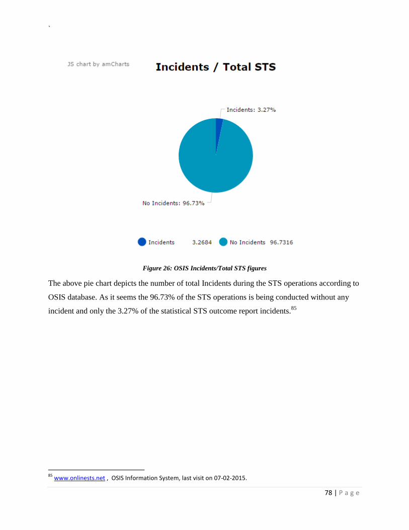
`
78 | P a g e
Figure 26: OSIS Incidents/Total STS figures
The above pie chart depicts the number of total Incidents during the STS operations according to
OSIS database. As it seems the 96.73% of the STS operations is being conducted without any
incident and only the 3.27% of the statistical STS outcome report incidents.85
85
www.onlinests.net , OSIS Information System, last visit on 07-02-2015.
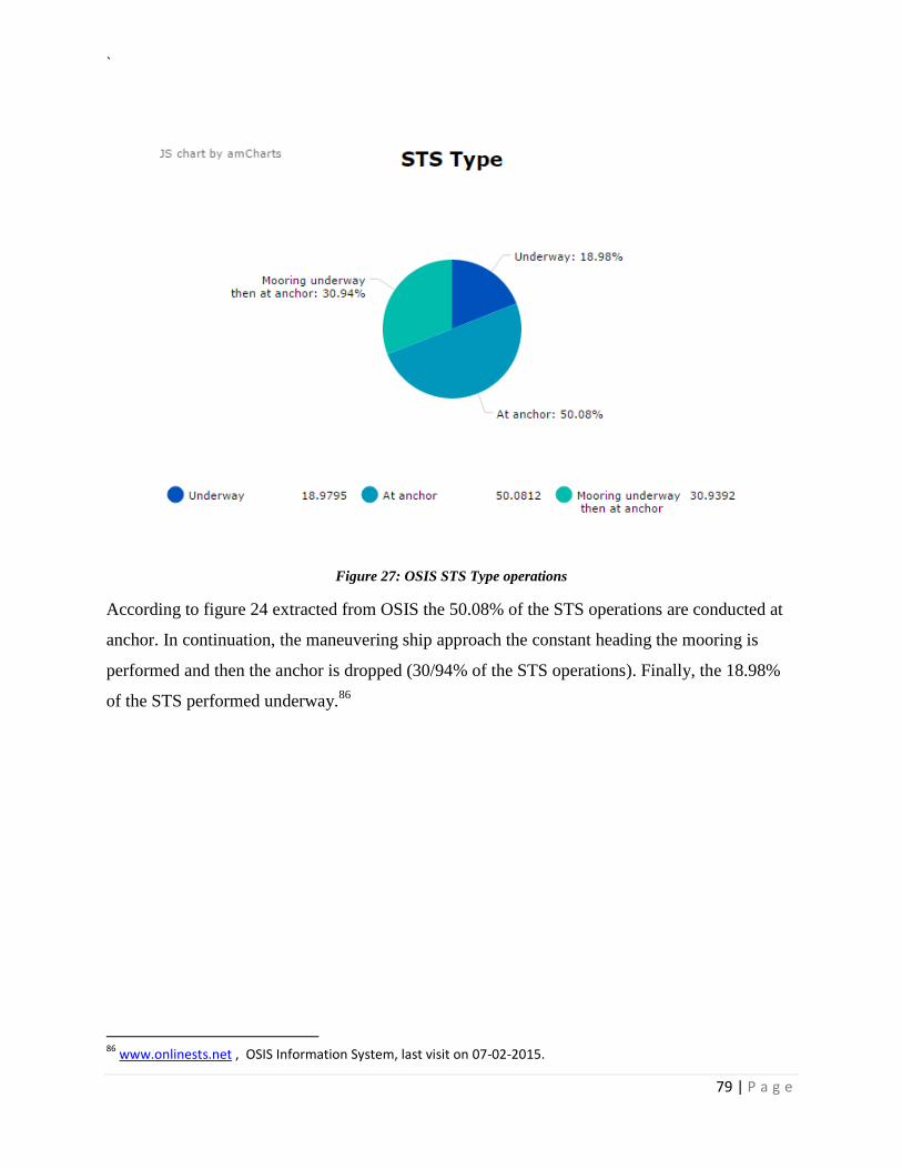
`
79 | P a g e
Figure 27: OSIS STS Type operations
According to figure 24 extracted from OSIS the 50.08% of the STS operations are conducted at
anchor. In continuation, the maneuvering ship approach the constant heading the mooring is
performed and then the anchor is dropped (30/94% of the STS operations). Finally, the 18.98%
of the STS performed underway.86
86
www.onlinests.net , OSIS Information System, last visit on 07-02-2015.
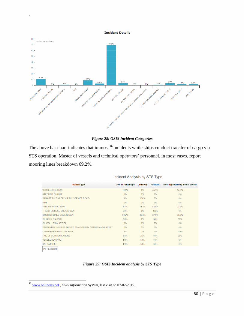
`
80 | P a g e
Figure 28: OSIS Incident Categories
The above bar chart indicates that in most 87
incidents while ships conduct transfer of cargo via
STS operation, Master of vessels and technical operators’ personnel, in most cases, report
mooring lines breakdown 69.2%.
Figure 29: OSIS Incident analysis by STS Type
87
www.onlinests.net , OSIS Information System, last visit on 07-02-2015.
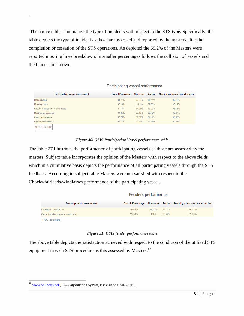
`
81 | P a g e
The above tables summarize the type of incidents with respect to the STS type. Specifically, the
table depicts the type of incident as those are assessed and reported by the masters after the
completion or cessation of the STS operations. As depicted the 69.2% of the Masters were
reported mooring lines breakdown. In smaller percentages follows the collision of vessels and
the fender breakdown.
Figure 30: OSIS Participating Vessel performance table
The table 27 illustrates the performance of participating vessels as those are assessed by the
masters. Subject table incorporates the opinion of the Masters with respect to the above fields
which in a cumulative basis depicts the performance of all participating vessels through the STS
feedback. According to subject table Masters were not satisfied with respect to the
Chocks/fairleads/windlasses performance of the participating vessel.
Figure 31: OSIS fender performance table
The above table depicts the satisfaction achieved with respect to the condition of the utilized STS
equipment in each STS procedure as this assessed by Masters.88
88
www.onlinests.net , OSIS Information System, last visit on 07-02-2015.
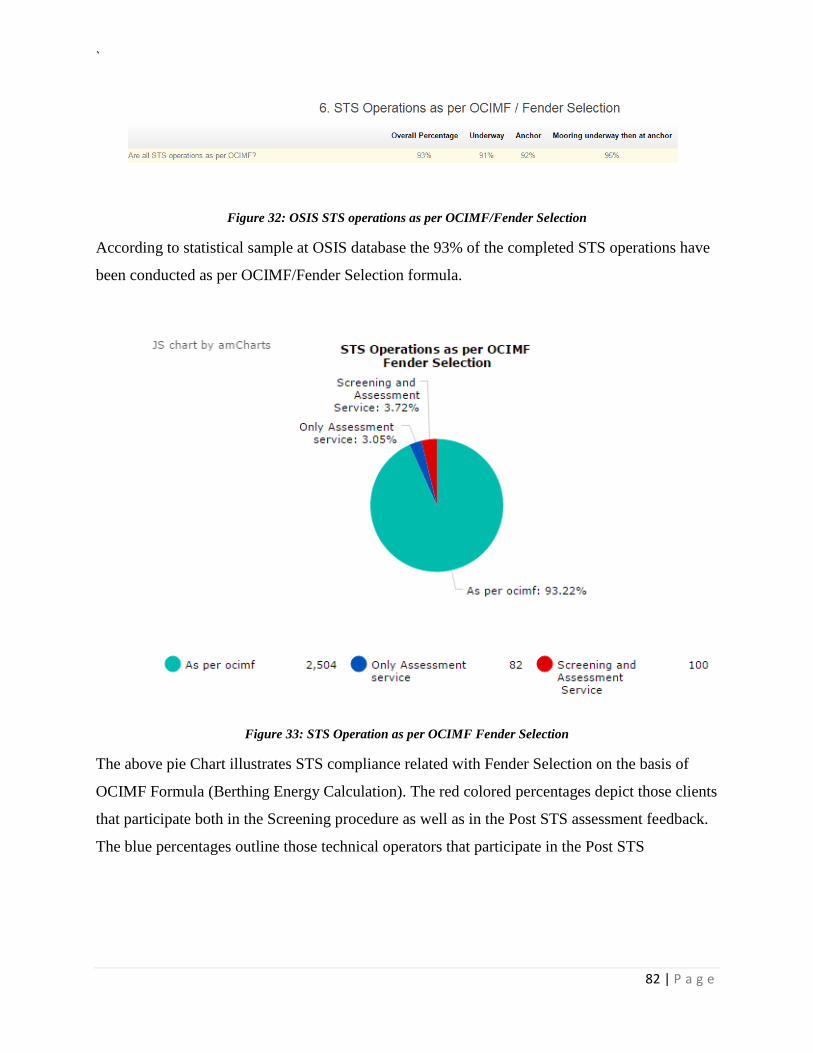
`
82 | P a g e
Figure 32: OSIS STS operations as per OCIMF/Fender Selection
According to statistical sample at OSIS database the 93% of the completed STS operations have
been conducted as per OCIMF/Fender Selection formula.
Figure 33: STS Operation as per OCIMF Fender Selection
The above pie Chart illustrates STS compliance related with Fender Selection on the basis of
OCIMF Formula (Berthing Energy Calculation). The red colored percentages depict those clients
that participate both in the Screening procedure as well as in the Post STS assessment feedback.
The blue percentages outline those technical operators that participate in the Post STS
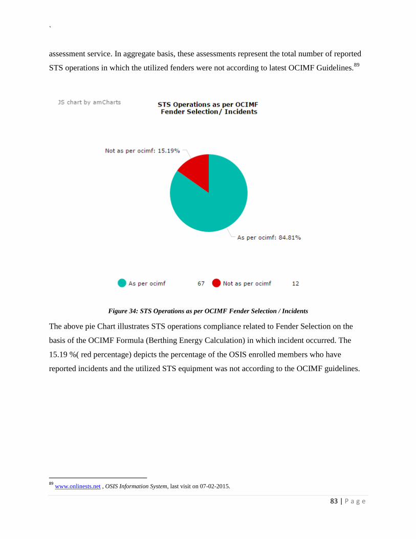
`
83 | P a g e
assessment service. In aggregate basis, these assessments represent the total number of reported
STS operations in which the utilized fenders were not according to latest OCIMF Guidelines.89
Figure 34: STS Operations as per OCIMF Fender Selection / Incidents
The above pie Chart illustrates STS operations compliance related to Fender Selection on the
basis of the OCIMF Formula (Berthing Energy Calculation) in which incident occurred. The
15.19 %( red percentage) depicts the percentage of the OSIS enrolled members who have
reported incidents and the utilized STS equipment was not according to the OCIMF guidelines.
89
www.onlinests.net , OSIS Information System, last visit on 07-02-2015.
`
84 | P a g e
Conclusion
The scope of this dissertation was, to introduce a fairly recent framework that established in the
Marine and Maritime industry on July 2009 and related to the new voted by member states
resolution of IMO. This resolution prescribes how STS operations should be conducted and how
nominated vessels should justify the commercial representation and compliance according to
industry standards.
Undoubtedly, due to high risk nature of such operations, the commercial need has been
identified, recognized and ratified by member states of IMO. The resolution of IMO of July 2009
illustrates directly and indirectly the majors stakeholders’ (Tanker Owners, Technical Managers,
Charterers) interests and concerns on the encountered risks and the liability exposure. The
adoption of the due “diligence concept” indicates the culture of the Owners towards highest
safety standards. The safety culture illustrated by the properly dealing of such operations through
the adoption and establishment of procedures prior during and after the STS operation.
Prior the commencement of the STS operation, through the screening procedure, technical
managers are able to verify the compliance of vessels according to industry standards and the
STS Plan Policies.
During the STS operation, a suitable risk assessment will evaluate the potential risks and
propose risk reduction measures according to industry best practices.
After the STS operation, the STS feedback from the Master will produce the STS knowledge
which will be disseminated to the entire fleet, offshore, onshore personnel and industry interest
groups.
`
85 | P a g e
Bibliography
ICS/OCIMF/SIGTTO/CDI Ship to Ship Transfer Guide for Petroleum, Chemicals and
Liquefied Gases”edition 4 2013.
DYNAMARINe& Clyde & Co. “Frequently Asked Questions in Ship to Ship transfer
Operations”
IMO-Manual on Oil Pollution Section I – “Prevention”.
HELMEPA Maritime Training Centre. Presentation from the Voluntary Refresher
Training Program, “Getting the Best out of the Worst: Methods for a constructive
incident analysis”
Det Norske Veritas -OFFSHORE TECHNOLOGY REPORT 2001/063, “Marine risk
assessment”, Prepared for the Health and Safety Executive.
A. Glykas, S. Perissakis, “A risk assessment methodology as a tool for screening of Ship-
to-Ship (STS) transfer operations.” ECONSHIP 2011.
The Yokohama Rubber CO.LTD.,“Yokohama floating fenders Pneumatic 50&80”,
Catalog No AF/CAT /2006/0.
The Yokohama Rubber CO.LTD., “Manual for Yokohama Pneumatic Rubber Fenders”,
handling manual. No. FD 04.
Yokohama , Wan, Fumihiko Yazaki, Sigeki Sakakibara, “Fender selection for STS
operation circular”, Maurice the Yokohama Rubber Co., Ltd., Ref: SF06070.
IMO-RESOLUTION MEPC.186(59) Adopted on 17 July 2009.
IMO-Maritime safety committee, FORMAL SAFETY ASSESSMENT, “Consolidated text of the
Guidelines for Formal Safety Assessment (FSA) for use in the IMO rule-making process
(MSC/Circ.1023−MEPC/Circ.392
EN 1765 Rubber Hose Assemblies for Oil Suction and Discharge Services, 2004
EN 13765 Thermoplastic MUlti-layer (Non-vulcanized) Hoses and Hose Assemblies for the
Transfer of Hydrocarbons, Solvents and Chemicals, 2010
ISO 10380 Corrugated Metal Hoses and Hose Assemblies, 2003
ISO 2928 Rubber Hoses and Hose Assemblies for Liquefied Petroleum Gas (LPG) in
the Liquid or Gaseous Phase and Natural Gas up to 25 bar (2.5 MPa), 2003
`
86 | P a g e
EN 13766 Thermoplastic MUlti-layer (Non-vulcanised) Hoses and Hose Assemblies for
the Transfer of Liquid Petroleum Gas and Liquefied Natural Gas, 2010
EN 1474-2 Installation and Equipment for Liquefied Natural Gas - Design and Testing
of Marine Transfer Systems, Part 2: Design and Testing ofTransfer Hoses, 2008
EN ISO 8330:2008 Rubber and Plastics Hoses and Hose Assemblies -Vocabulary
EN ISO 8031 :2009 Rubber and Plastics Hoses and Hose Assemblies - Determination of
Electrical Resistance and Conductivity
`
87 | P a g e
Web Data
www.bimco.org , “STS transfer Clause”, last update on 09.12.08.
https://www.bimco.org/Chartering/Clauses_and_Documents/Clauses/Ship_to%20Ship_T
ransfer_Clause_for_Time_Charter.aspx
http://www.hse.gov.uk/ , “Risk Theory – ALARP”, last update on 01-09-2014.
http://www.hse.gov.uk/risk/theory/alarpglance.htm
www.onlinests.net , OSIS STS MAP, last visit on 07-12-2015.
http://www.onlinests.net/index.php?option=com_stsmap , last visit on 01-02-2016.
www.onlinests.net, OSIS DATABASE.
http://www.onlinests.net/index.php?option=com_overall&Itemid=140 +
www.q88.com
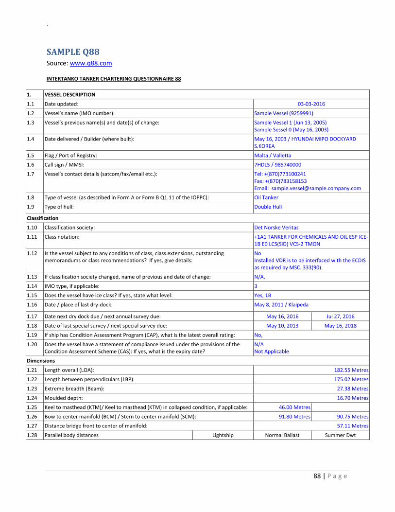
`
88 | P a g e
SAMPLE Q88 Source: www.q88.com
INTERTANKO TANKER CHARTERING QUESTIONNAIRE 88
1. VESSEL DESCRIPTION
1.1 Date updated: 03-03-2016
1.2 Vessel’s name (IMO number): Sample Vessel (9259991)
1.3 Vessel’s previous name(s) and date(s) of change: Sample Vessel 1 (Jun 13, 2005) Sample Sessel 0 (May 16, 2003)
1.4 Date delivered / Builder (where built): May 16, 2003 / HYUNDAI MIPO DOCKYARD S.KOREA
1.5 Flag / Port of Registry: Malta / Valletta
1.6 Call sign / MMSI: 7HDL5 / 985740000
1.7 Vessel’s contact details (satcom/fax/email etc.): Tel: +(870)773100241 Fax: +(870)783158153 Email: [email protected]
1.8 Type of vessel (as described in Form A or Form B Q1.11 of the IOPPC): Oil Tanker
1.9 Type of hull: Double Hull
Classification
1.10 Classification society: Det Norske Veritas
1.11 Class notation: +1A1 TANKER FOR CHEMICALS AND OIL ESP ICE-1B E0 LCS(SID) VCS-2 TMON
1.12 Is the vessel subject to any conditions of class, class extensions, outstanding memorandums or class recommendations? If yes, give details:
No Installed VDR is to be interfaced with the ECDIS as required by MSC. 333(90).
1.13 If classification society changed, name of previous and date of change: N/A,
1.14 IMO type, if applicable: 3
1.15 Does the vessel have ice class? If yes, state what level: Yes, 1B
1.16 Date / place of last dry-dock: May 8, 2011 / Klaipeda
1.17 Date next dry dock due / next annual survey due: May 16, 2016 Jul 27, 2016
1.18 Date of last special survey / next special survey due: May 10, 2013 May 16, 2018
1.19 If ship has Condition Assessment Program (CAP), what is the latest overall rating: No,
1.20 Does the vessel have a statement of compliance issued under the provisions of the Condition Assessment Scheme (CAS): If yes, what is the expiry date?
N/A Not Applicable
Dimensions
1.21 Length overall (LOA): 182.55 Metres
1.22 Length between perpendiculars (LBP): 175.02 Metres
1.23 Extreme breadth (Beam): 27.38 Metres
1.24 Moulded depth: 16.70 Metres
1.25 Keel to masthead (KTM)/ Keel to masthead (KTM) in collapsed condition, if applicable: 46.00 Metres
1.26 Bow to center manifold (BCM) / Stern to center manifold (SCM): 91.80 Metres 90.75 Metres
1.27 Distance bridge front to center of manifold: 57.11 Metres
1.28 Parallel body distances Lightship Normal Ballast Summer Dwt
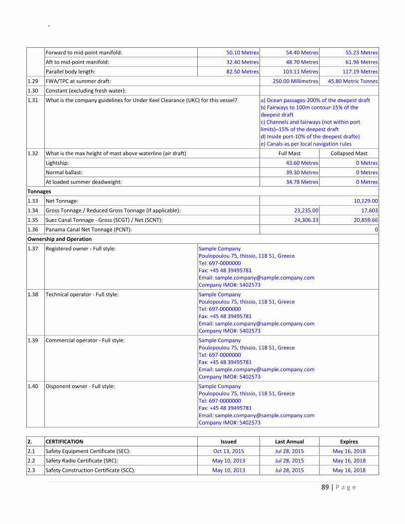
`
89 | P a g e
Forward to mid-point manifold: 50.10 Metres 54.40 Metres 55.23 Metres
Aft to mid-point manifold: 32.40 Metres 48.70 Metres 61.96 Metres
Parallel body length: 82.50 Metres 103.11 Metres 117.19 Metres
1.29 FWA/TPC at summer draft: 250.00 Millimetres 45.80 Metric Tonnes
1.30 Constant (excluding fresh water):
1.31 What is the company guidelines for Under Keel Clearance (UKC) for this vessel? a) Ocean passages-200% of the deepest draft b) Fairways to 100m contour-15% of the deepest draft c) Channels and fairways (not within port limits)–15% of the deepest draft d) Inside port-10% of the deepest drafte) e) Canals-as per local navigation rules
1.32 What is the max height of mast above waterline (air draft) Full Mast Collapsed Mast
Lightship: 43.60 Metres 0 Metres
Normal ballast: 39.30 Metres 0 Metres
At loaded summer deadweight: 34.78 Metres 0 Metres
Tonnages
1.33 Net Tonnage: 10,129.00
1.34 Gross Tonnage / Reduced Gross Tonnage (if applicable): 23,235.00 17,603
1.35 Suez Canal Tonnage - Gross (SCGT) / Net (SCNT): 24,306.33 20,859.66
1.36 Panama Canal Net Tonnage (PCNT): 0
Ownership and Operation
1.37 Registered owner - Full style:
Sample Company Poulopoulou 75, thissio, 118 51, Greece Tel: 697-0000000 Fax: +45 48 39495781 Email: [email protected] Company IMO#: 5402573
1.38 Technical operator - Full style:
Sample Company Poulopoulou 75, thissio, 118 51, Greece Tel: 697-0000000 Fax: +45 48 39495781 Email: [email protected] Company IMO#: 5402573
1.39 Commercial operator - Full style:
Sample Company Poulopoulou 75, thissio, 118 51, Greece Tel: 697-0000000 Fax: +45 48 39495781 Email: [email protected] Company IMO#: 5402573
1.40 Disponent owner - Full style:
Sample Company Poulopoulou 75, thissio, 118 51, Greece Tel: 697-0000000 Fax: +45 48 39495781 Email: [email protected] Company IMO#: 5402573
2. CERTIFICATION Issued Last Annual Expires
2.1 Safety Equipment Certificate (SEC): Oct 13, 2015 Jul 28, 2015 May 16, 2018
2.2 Safety Radio Certificate (SRC): May 10, 2013 Jul 28, 2015 May 16, 2018
2.3 Safety Construction Certificate (SCC): May 10, 2013 Jul 28, 2015 May 16, 2018
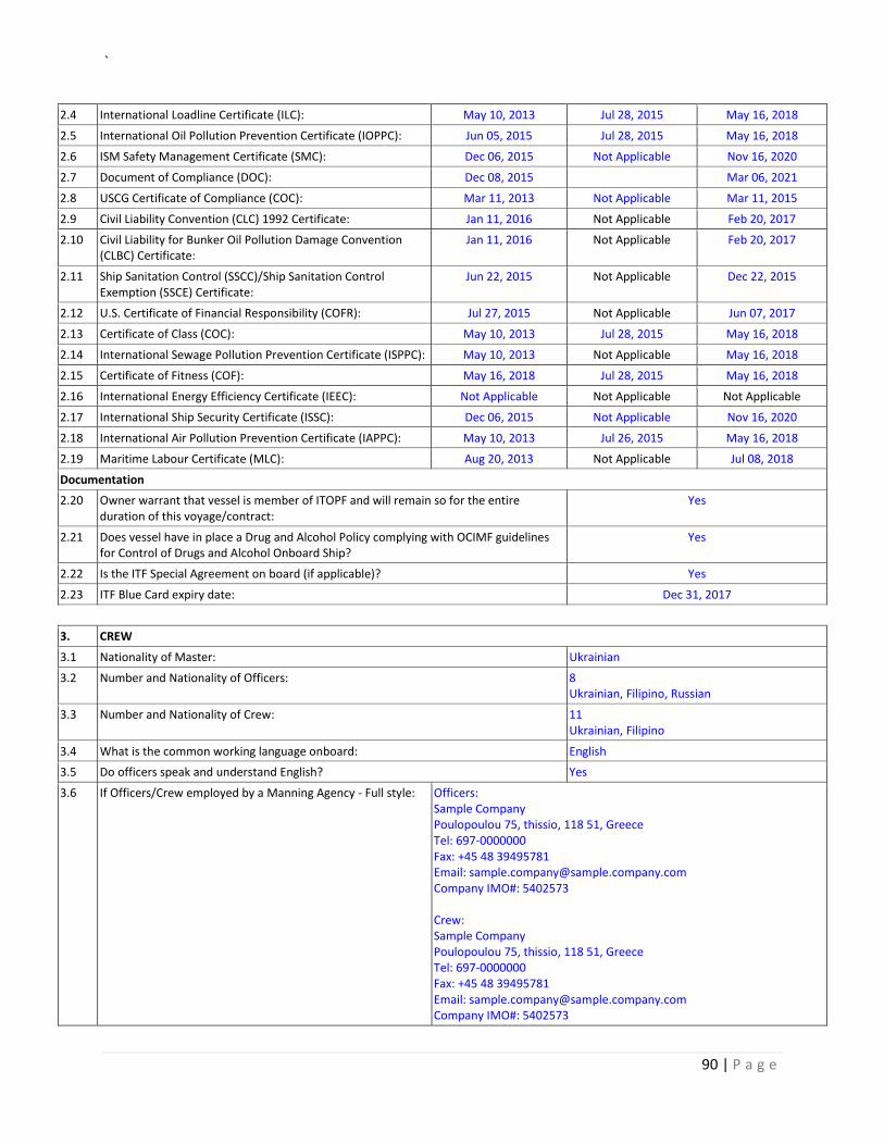
`
90 | P a g e
2.4 International Loadline Certificate (ILC): May 10, 2013 Jul 28, 2015 May 16, 2018
2.5 International Oil Pollution Prevention Certificate (IOPPC): Jun 05, 2015 Jul 28, 2015 May 16, 2018
2.6 ISM Safety Management Certificate (SMC): Dec 06, 2015 Not Applicable Nov 16, 2020
2.7 Document of Compliance (DOC): Dec 08, 2015 Mar 06, 2021
2.8 USCG Certificate of Compliance (COC): Mar 11, 2013 Not Applicable Mar 11, 2015
2.9 Civil Liability Convention (CLC) 1992 Certificate: Jan 11, 2016 Not Applicable Feb 20, 2017
2.10 Civil Liability for Bunker Oil Pollution Damage Convention (CLBC) Certificate:
Jan 11, 2016 Not Applicable Feb 20, 2017
2.11 Ship Sanitation Control (SSCC)/Ship Sanitation Control Exemption (SSCE) Certificate:
Jun 22, 2015 Not Applicable Dec 22, 2015
2.12 U.S. Certificate of Financial Responsibility (COFR): Jul 27, 2015 Not Applicable Jun 07, 2017
2.13 Certificate of Class (COC): May 10, 2013 Jul 28, 2015 May 16, 2018
2.14 International Sewage Pollution Prevention Certificate (ISPPC): May 10, 2013 Not Applicable May 16, 2018
2.15 Certificate of Fitness (COF): May 16, 2018 Jul 28, 2015 May 16, 2018
2.16 International Energy Efficiency Certificate (IEEC): Not Applicable Not Applicable Not Applicable
2.17 International Ship Security Certificate (ISSC): Dec 06, 2015 Not Applicable Nov 16, 2020
2.18 International Air Pollution Prevention Certificate (IAPPC): May 10, 2013 Jul 26, 2015 May 16, 2018
2.19 Maritime Labour Certificate (MLC): Aug 20, 2013 Not Applicable Jul 08, 2018
Documentation
2.20 Owner warrant that vessel is member of ITOPF and will remain so for the entire duration of this voyage/contract:
Yes
2.21 Does vessel have in place a Drug and Alcohol Policy complying with OCIMF guidelines for Control of Drugs and Alcohol Onboard Ship?
Yes
2.22 Is the ITF Special Agreement on board (if applicable)? Yes
2.23 ITF Blue Card expiry date: Dec 31, 2017
3. CREW
3.1 Nationality of Master: Ukrainian
3.2 Number and Nationality of Officers: 8 Ukrainian, Filipino, Russian
3.3 Number and Nationality of Crew: 11 Ukrainian, Filipino
3.4 What is the common working language onboard: English
3.5 Do officers speak and understand English? Yes
3.6 If Officers/Crew employed by a Manning Agency - Full style: Officers: Sample Company Poulopoulou 75, thissio, 118 51, Greece Tel: 697-0000000 Fax: +45 48 39495781 Email: [email protected] Company IMO#: 5402573 Crew: Sample Company Poulopoulou 75, thissio, 118 51, Greece Tel: 697-0000000 Fax: +45 48 39495781 Email: [email protected] Company IMO#: 5402573
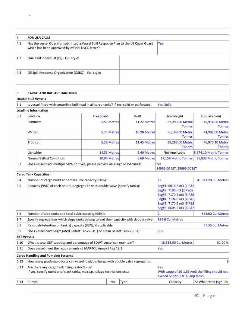
`
91 | P a g e
4. FOR USA CALLS
4.1 Has the vessel Operator submitted a Vessel Spill Response Plan to the US Coast Guard which has been approved by official USCG letter?
Yes
4.2 Qualified individual (QI) - Full style:
4.3 Oil Spill Response Organization (OSRO) - Full style:
5. CARGO AND BALLAST HANDLING
Double Hull Vessels
5.1 Is vessel fitted with centerline bulkhead in all cargo tanks? If Yes, solid or perforated: Yes, Solid
Loadline Information
5.2 Loadline Freeboard Draft Deadweight Displacement
Summer: 5.51 Metres 11.22 Metres 37,299.90 Metric Tonnes
45,974.00 Metric Tonnes
Winter: 5.75 Metres 10.98 Metres 36,148.00 Metric Tonnes
44,902.00 Metric Tonnes
Tropical: 5.28 Metres 11.45 Metres 38,296.00 Metric Tonnes
46,970.10 Metric Tonnes
Lightship: 14.33 Metres 2.40 Metres Not Applicable 8,674.10 Metric Tonnes
Normal Ballast Condition: 10.04 Metres 6.69 Metres 17,159 Metric Tonnes 25,833 Metric Tonnes
5.3 Does vessel have multiple SDWT? If yes, please provide all assigned loadlines: Yes 34999.00 MT, 29999.00 MT
Cargo Tank Capacities
5.4 Number of cargo tanks and total cubic capacity (98%): 12 41,343.20 Cu. Metres
5.5 Capacity (98%) of each natural segregation with double valve (specify tanks): Seg#1: 6016.8 m3 (1 P&S) Seg#2: 7186 m3 (2 P&S) Seg#3: 7170.2 m3 (3 P&S) Seg#4: 7194.8 m3 (4 P&S) Seg#5: 7170.2 m3 (5 P&S) Seg#6: 6605.2 m3 (6 P&S)
5.6 Number of slop tanks and total cubic capacity (98%): 2 864.60 Cu. Metres
5.7 Specify segregations which slops tanks belong to and their capacity with double valve: 864.6 Cu. Metres
5.8 Residual/Retention oil tank(s) capacity (98%), if applicable: 67.36 Cu. Metres
5.9 Does vessel have Segregated Ballast Tanks (SBT) or Clean Ballast Tanks (CBT): SBT
SBT Vessels
5.10 What is total SBT capacity and percentage of SDWT vessel can maintain? 18,983.00 Cu. Metres 51.00 %
5.11 Does vessel meet the requirements of MARPOL Annex I Reg 18.2: Yes
Cargo Handling and Pumping Systems
5.12 How many grades/products can vessel load/discharge with double valve segregation: 6
5.13 Are there any cargo tank filling restrictions? If yes, specify number of slack tanks, max s.g., ullage restrictions etc.:
Yes With cargo of SG 1.55t/m3 the filling should not exceed 66 for COT & Slop tanks.
5.14 Pumps No. Type Capacity At What Head (sg=1.0)
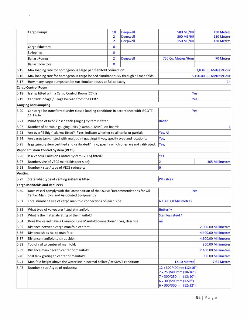
`
92 | P a g e
Cargo Pumps: 10 2 2
Deepwell Deepwell Deepwell
500 M3/HR 300 M3/HR 150 M3/HR
130 Meters 130 Meters 130 Meters
Cargo Eductors: 0
Stripping: 0
Ballast Pumps: 2 Deepwell 750 Cu. Metres/Hour 70 Metres
Ballast Eductors: 0
5.15 Max loading rate for homogenous cargo per manifold connection: 1,834 Cu. Metres/Hour
5.16 Max loading rate for homogenous cargo loaded simultaneously through all manifolds: 5,150.00 Cu. Metres/Hour
5.17 How many cargo pumps can be run simultaneously at full capacity: 14
Cargo Control Room
5.18 Is ship fitted with a Cargo Control Room (CCR)? Yes
5.19 Can tank innage / ullage be read from the CCR? Yes
Gauging and Sampling
5.20 Can cargo be transferred under closed loading conditions in accordance with ISGOTT 11.1.6.6?
Yes
5.21 What type of fixed closed tank gauging system is fitted: Radar
5.22 Number of portable gauging units (example- MMC) on board: 4
5.23 Are overfill (high) alarms fitted? If Yes, indicate whether to all tanks or partial: Yes, All
5.24 Are cargo tanks fitted with multipoint gauging? If yes, specify type and locations: Yes,
5.25 Is gauging system certified and calibrated? If no, specify which ones are not calibrated: Yes,
Vapor Emission Control System (VECS)
5.26 Is a Vapour Emission Control System (VECS) fitted? Yes
5.27 Number/size of VECS manifolds (per side): 2 305 Millimetres
5.28 Number / size / type of VECS reducers: 0
Venting
5.29 State what type of venting system is fitted: PV valves
Cargo Manifolds and Reducers
5.30 Does vessel comply with the latest edition of the OCIMF 'Recommendations for Oil Tanker Manifolds and Associated Equipment’?
Yes
5.31 Total number / size of cargo manifold connections on each side: 6 / 305.00 Millimetres
5.32 What type of valves are fitted at manifold: Butterfly
5.33 What is the material/rating of the manifold: Stainless steel /
5.34 Does the vessel have a Common Line Manifold connection? If yes, describe: na
5.35 Distance between cargo manifold centers: 2,000.00 Millimetres
5.36 Distance ships rail to manifold: 4,400.00 Millimetres
5.37 Distance manifold to ships side: 4,600.00 Millimetres
5.38 Top of rail to center of manifold: 850.00 Millimetres
5.39 Distance main deck to center of manifold: 2,100.00 Millimetres
5.40 Spill tank grating to center of manifold: 900.00 Millimetres
5.41 Manifold height above the waterline in normal ballast / at SDWT condition: 12.10 Metres 7.61 Metres
5.42 Number / size / type of reducers:
12 x 300/400mm (12/16") 2 x 250/400mm (10/16") 7 x 300/250mm (12/10") 6 x 300/200mm (12/8") 6 x 300/300mm (12/12")
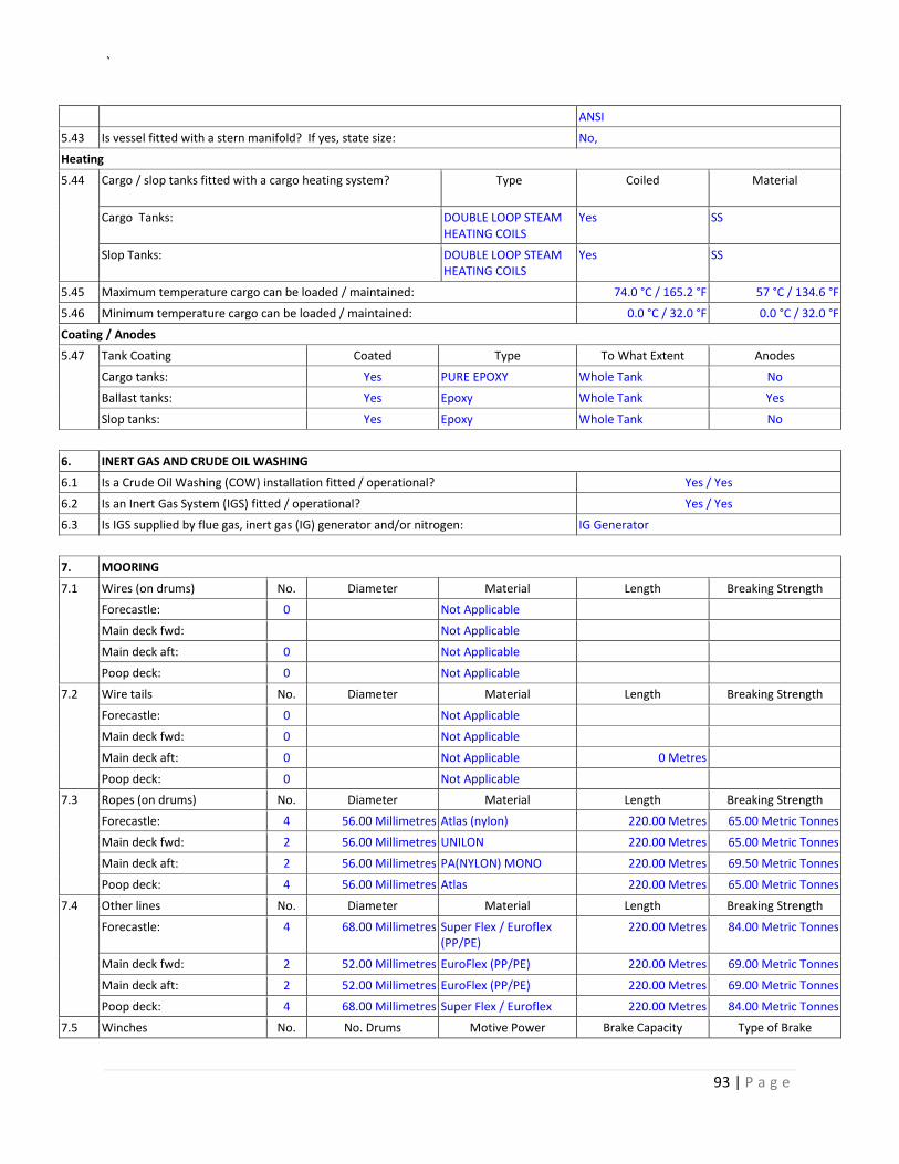
`
93 | P a g e
ANSI
5.43 Is vessel fitted with a stern manifold? If yes, state size: No,
Heating
5.44 Cargo / slop tanks fitted with a cargo heating system?
Type
Coiled Material
Cargo Tanks: DOUBLE LOOP STEAM HEATING COILS
Yes SS
Slop Tanks: DOUBLE LOOP STEAM HEATING COILS
Yes SS
5.45 Maximum temperature cargo can be loaded / maintained: 74.0 °C / 165.2 °F 57 °C / 134.6 °F
5.46 Minimum temperature cargo can be loaded / maintained: 0.0 °C / 32.0 °F 0.0 °C / 32.0 °F
Coating / Anodes
5.47 Tank Coating Coated Type To What Extent Anodes
Cargo tanks: Yes PURE EPOXY Whole Tank No
Ballast tanks: Yes Epoxy Whole Tank Yes
Slop tanks: Yes Epoxy Whole Tank No
6. INERT GAS AND CRUDE OIL WASHING
6.1 Is a Crude Oil Washing (COW) installation fitted / operational? Yes / Yes
6.2 Is an Inert Gas System (IGS) fitted / operational? Yes / Yes
6.3 Is IGS supplied by flue gas, inert gas (IG) generator and/or nitrogen: IG Generator
7. MOORING
7.1 Wires (on drums) No. Diameter Material Length Breaking Strength
Forecastle: 0 Not Applicable
Main deck fwd: Not Applicable
Main deck aft: 0 Not Applicable
Poop deck: 0 Not Applicable
7.2 Wire tails No. Diameter Material Length Breaking Strength
Forecastle: 0 Not Applicable
Main deck fwd: 0 Not Applicable
Main deck aft: 0 Not Applicable 0 Metres
Poop deck: 0 Not Applicable
7.3 Ropes (on drums) No. Diameter Material Length Breaking Strength
Forecastle: 4 56.00 Millimetres Atlas (nylon) 220.00 Metres 65.00 Metric Tonnes
Main deck fwd: 2 56.00 Millimetres UNILON 220.00 Metres 65.00 Metric Tonnes
Main deck aft: 2 56.00 Millimetres PA(NYLON) MONO 220.00 Metres 69.50 Metric Tonnes
Poop deck: 4 56.00 Millimetres Atlas 220.00 Metres 65.00 Metric Tonnes
7.4 Other lines No. Diameter Material Length Breaking Strength
Forecastle: 4 68.00 Millimetres Super Flex / Euroflex (PP/PE)
220.00 Metres 84.00 Metric Tonnes
Main deck fwd: 2 52.00 Millimetres EuroFlex (PP/PE) 220.00 Metres 69.00 Metric Tonnes
Main deck aft: 2 52.00 Millimetres EuroFlex (PP/PE) 220.00 Metres 69.00 Metric Tonnes
Poop deck: 4 68.00 Millimetres Super Flex / Euroflex 220.00 Metres 84.00 Metric Tonnes
7.5 Winches No. No. Drums Motive Power Brake Capacity Type of Brake
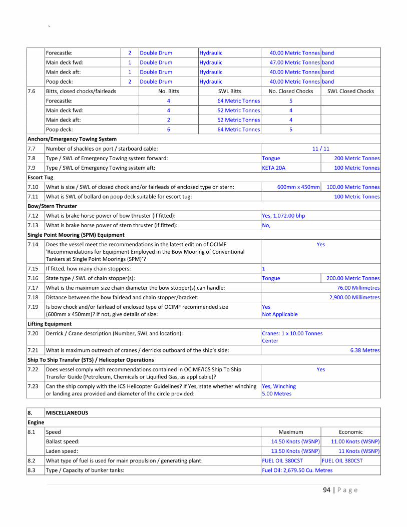
`
94 | P a g e
Forecastle: 2 Double Drum Hydraulic 40.00 Metric Tonnes band
Main deck fwd: 1 Double Drum Hydraulic 47.00 Metric Tonnes band
Main deck aft: 1 Double Drum Hydraulic 40.00 Metric Tonnes band
Poop deck: 2 Double Drum Hydraulic 40.00 Metric Tonnes band
7.6 Bitts, closed chocks/fairleads No. Bitts SWL Bitts No. Closed Chocks SWL Closed Chocks
Forecastle: 4 64 Metric Tonnes 5
Main deck fwd: 4 52 Metric Tonnes 4
Main deck aft: 2 52 Metric Tonnes 4
Poop deck: 6 64 Metric Tonnes 5
Anchors/Emergency Towing System
7.7 Number of shackles on port / starboard cable: 11 / 11
7.8 Type / SWL of Emergency Towing system forward: Tongue 200 Metric Tonnes
7.9 Type / SWL of Emergency Towing system aft: KETA 20A 100 Metric Tonnes
Escort Tug
7.10 What is size / SWL of closed chock and/or fairleads of enclosed type on stern: 600mm x 450mm 100.00 Metric Tonnes
7.11 What is SWL of bollard on poop deck suitable for escort tug: 100 Metric Tonnes
Bow/Stern Thruster
7.12 What is brake horse power of bow thruster (if fitted): Yes, 1,072.00 bhp
7.13 What is brake horse power of stern thruster (if fitted): No,
Single Point Mooring (SPM) Equipment
7.14 Does the vessel meet the recommendations in the latest edition of OCIMF 'Recommendations for Equipment Employed in the Bow Mooring of Conventional Tankers at Single Point Moorings (SPM)’?
Yes
7.15 If fitted, how many chain stoppers: 1
7.16 State type / SWL of chain stopper(s): Tongue 200.00 Metric Tonnes
7.17 What is the maximum size chain diameter the bow stopper(s) can handle: 76.00 Millimetres
7.18 Distance between the bow fairlead and chain stopper/bracket: 2,900.00 Millimetres
7.19 Is bow chock and/or fairlead of enclosed type of OCIMF recommended size (600mm x 450mm)? If not, give details of size:
Yes Not Applicable
Lifting Equipment
7.20 Derrick / Crane description (Number, SWL and location): Cranes: 1 x 10.00 Tonnes Center
7.21 What is maximum outreach of cranes / derricks outboard of the ship’s side: 6.38 Metres
Ship To Ship Transfer (STS) / Helicopter Operations
7.22 Does vessel comply with recommendations contained in OCIMF/ICS Ship To Ship Transfer Guide (Petroleum, Chemicals or Liquified Gas, as applicable)?
Yes
7.23 Can the ship comply with the ICS Helicopter Guidelines? If Yes, state whether winching or landing area provided and diameter of the circle provided:
Yes, Winching 5.00 Metres
8. MISCELLANEOUS
Engine
8.1 Speed Maximum Economic
Ballast speed: 14.50 Knots (WSNP) 11.00 Knots (WSNP)
Laden speed: 13.50 Knots (WSNP) 11 Knots (WSNP)
8.2 What type of fuel is used for main propulsion / generating plant: FUEL OIL 380CST FUEL OIL 380CST
8.3 Type / Capacity of bunker tanks: Fuel Oil: 2,679.50 Cu. Metres
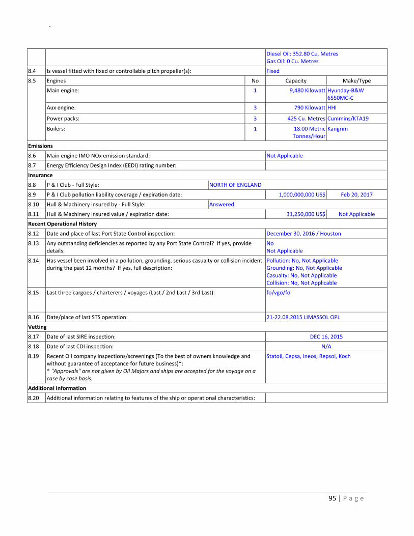
`
95 | P a g e
Diesel Oil: 352.80 Cu. Metres Gas Oil: 0 Cu. Metres
8.4 Is vessel fitted with fixed or controllable pitch propeller(s): Fixed
8.5 Engines No Capacity Make/Type
Main engine: 1 9,480 Kilowatt Hyunday-B&W 6550MC-C
Aux engine: 3 790 Kilowatt HHI
Power packs: 3 425 Cu. Metres Cummins/KTA19
Boilers: 1 18.00 Metric Tonnes/Hour
Kangrim
Emissions
8.6 Main engine IMO NOx emission standard: Not Applicable
8.7 Energy Efficiency Design Index (EEDI) rating number:
Insurance
8.8 P & I Club - Full Style: NORTH OF ENGLAND
8.9 P & I Club pollution liability coverage / expiration date: 1,000,000,000 US$ Feb 20, 2017
8.10 Hull & Machinery insured by - Full Style: Answered
8.11 Hull & Machinery insured value / expiration date: 31,250,000 US$ Not Applicable
Recent Operational History
8.12 Date and place of last Port State Control inspection: December 30, 2016 / Houston
8.13 Any outstanding deficiencies as reported by any Port State Control? If yes, provide details:
No Not Applicable
8.14 Has vessel been involved in a pollution, grounding, serious casualty or collision incident during the past 12 months? If yes, full description:
Pollution: No, Not Applicable Grounding: No, Not Applicable Casualty: No, Not Applicable Collision: No, Not Applicable
8.15 Last three cargoes / charterers / voyages (Last / 2nd Last / 3rd Last):
fo/vgo/fo
8.16 Date/place of last STS operation: 21-22.08.2015 LIMASSOL OPL
Vetting
8.17 Date of last SIRE inspection: DEC 16, 2015
8.18 Date of last CDI inspection: N/A
8.19 Recent Oil company inspections/screenings (To the best of owners knowledge and without guarantee of acceptance for future business)*: * "Approvals" are not given by Oil Majors and ships are accepted for the voyage on a case by case basis.
Statoil, Cepsa, Ineos, Repsol, Koch
Additional Information
8.20 Additional information relating to features of the ship or operational characteristics: