The Morningstar Energy Box- An Unusual Electromagnetic · PDF fileThe Morningstar Energy Box-...
12
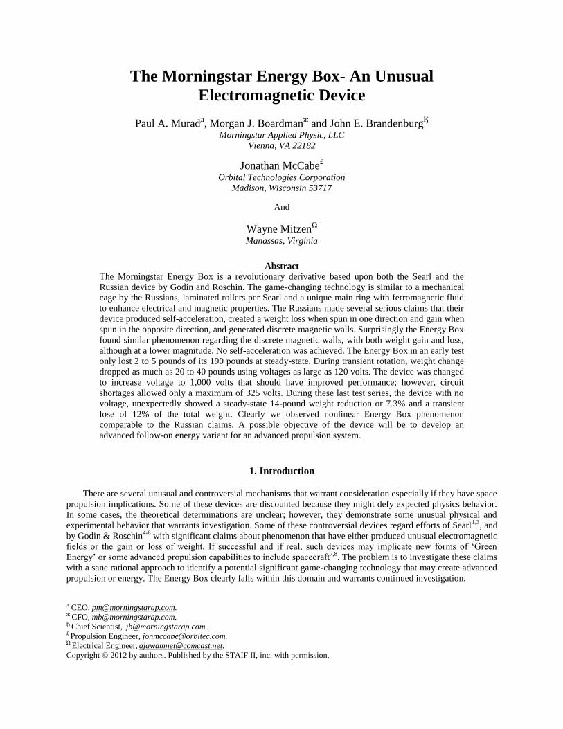
The Morningstar Energy Box- An Unusual Electromagnetic Device Paul A. Murad д , Morgan J. Boardman ж and John E. Brandenburg Ӄ Morningstar Applied Physic, LLC Vienna, VA 22182 Jonathan McCabe ₤ Orbital Technologies Corporation Madison, Wisconsin 53717 And Wayne Mitzen Ώ Manassas, Virginia Abstract The Morningstar Energy Box is a revolutionary derivative based upon both the Searl and the Russian device by Godin and Roschin. The game-changing technology is similar to a mechanical cage by the Russians, laminated rollers per Searl and a unique main ring with ferromagnetic fluid to enhance electrical and magnetic properties. The Russians made several serious claims that their device produced self-acceleration, created a weight loss when spun in one direction and gain when spun in the opposite direction, and generated discrete magnetic walls. Surprisingly the Energy Box found similar phenomenon regarding the discrete magnetic walls, with both weight gain and loss, although at a lower magnitude. No self-acceleration was achieved. The Energy Box in an early test only lost 2 to 5 pounds of its 190 pounds at steady-state. During transient rotation, weight change dropped as much as 20 to 40 pounds using voltages as large as 120 volts. The device was changed to increase voltage to 1,000 volts that should have improved performance; however, circuit shortages allowed only a maximum of 325 volts. During these last test series, the device with no voltage, unexpectedly showed a steady-state 14-pound weight reduction or 7.3% and a transient lose of 12% of the total weight. Clearly we observed nonlinear Energy Box phenomenon comparable to the Russian claims. A possible objective of the device will be to develop an advanced follow-on energy variant for an advanced propulsion system. 1. Introduction There are several unusual and controversial mechanisms that warrant consideration especially if they have space propulsion implications. Some of these devices are discounted because they might defy expected physics behavior. In some cases, the theoretical determinations are unclear; however, they demonstrate some unusual physical and experimental behavior that warrants investigation. Some of these controversial devices regard efforts of Searl 1,3 , and by Godin & Roschin 4-6 with significant claims about phenomenon that have either produced unusual electromagnetic fields or the gain or loss of weight. If successful and if real, such devices may implicate new forms of ‘Green Energy’ or some advanced propulsion capabilities to include spacecraft 7,8 . The problem is to investigate these claims with a sane rational approach to identify a potential significant game-changing technology that may create advanced propulsion or energy. The Energy Box clearly falls within this domain and warrants continued investigation. __________________________ д CEO, [email protected]. ж CFO, [email protected]. Ӄ Chief Scientist, [email protected]. ₤ Propulsion Engineer, [email protected]. Ώ Electrical Engineer, [email protected]. Copyright © 2012 by authors. Published by the STAIF II, inc. with permission.
-
Upload
truongcong -
Category
Documents
-
view
222 -
download
1
Transcript of The Morningstar Energy Box- An Unusual Electromagnetic · PDF fileThe Morningstar Energy Box-...
The Morningstar Energy Box- An Unusual
Electromagnetic Device
Paul A. Muradд, Morgan J. Boardman
ж and John E. Brandenburg
Ӄ
Morningstar Applied Physic, LLC
Vienna, VA 22182
Jonathan McCabe₤
Orbital Technologies Corporation
Madison, Wisconsin 53717
And
Wayne MitzenΏ
Manassas, Virginia
Abstract
The Morningstar Energy Box is a revolutionary derivative based upon both the Searl and the
Russian device by Godin and Roschin. The game-changing technology is similar to a mechanical
cage by the Russians, laminated rollers per Searl and a unique main ring with ferromagnetic fluid
to enhance electrical and magnetic properties. The Russians made several serious claims that their
device produced self-acceleration, created a weight loss when spun in one direction and gain when
spun in the opposite direction, and generated discrete magnetic walls. Surprisingly the Energy Box
found similar phenomenon regarding the discrete magnetic walls, with both weight gain and loss,
although at a lower magnitude. No self-acceleration was achieved. The Energy Box in an early test
only lost 2 to 5 pounds of its 190 pounds at steady-state. During transient rotation, weight change
dropped as much as 20 to 40 pounds using voltages as large as 120 volts. The device was changed
to increase voltage to 1,000 volts that should have improved performance; however, circuit
shortages allowed only a maximum of 325 volts. During these last test series, the device with no
voltage, unexpectedly showed a steady-state 14-pound weight reduction or 7.3% and a transient
lose of 12% of the total weight. Clearly we observed nonlinear Energy Box phenomenon
comparable to the Russian claims. A possible objective of the device will be to develop an
advanced follow-on energy variant for an advanced propulsion system.
1. Introduction
There are several unusual and controversial mechanisms that warrant consideration especially if they have space
propulsion implications. Some of these devices are discounted because they might defy expected physics behavior.
In some cases, the theoretical determinations are unclear; however, they demonstrate some unusual physical and
experimental behavior that warrants investigation. Some of these controversial devices regard efforts of Searl1,3
, and
by Godin & Roschin4-6
with significant claims about phenomenon that have either produced unusual electromagnetic
fields or the gain or loss of weight. If successful and if real, such devices may implicate new forms of ‘Green
Energy’ or some advanced propulsion capabilities to include spacecraft7,8
. The problem is to investigate these claims
with a sane rational approach to identify a potential significant game-changing technology that may create advanced
propulsion or energy. The Energy Box clearly falls within this domain and warrants continued investigation.
__________________________ д CEO, [email protected]. ж CFO, [email protected]. Ӄ Chief Scientist, [email protected]. ₤ Propulsion Engineer, [email protected]. Ώ Electrical Engineer, [email protected].
Copyright © 2012 by authors. Published by the STAIF II, inc. with permission.
2. Results and Discussion
2.1 Searl Device
The idea proposed by John Searl1-3
has created significant controversy. The basic idea of his device is that
cylindrical magnets will interact with a ferromagnetic bar of material. These magnets will diametrically approach a
certain displacement from the bar. Searl’s contribution bends the bar into a contiguous ring so that the individual
magnets ‘hunt’ and ‘peck’ in a circular arrangement with an equal azimuthal increment with respect to the ring. The
rollers actually stay above but do not contact the ring surface. His notion suggests that all of the magnets have either
all south or all north polarity. The other contribution by Searl is that the rollers and rings are laminated with specific
materials. For the roller, they consist of a central core that includes an intense magnet. These are inserted in a copper
sleeve followed by a dielectric material externally concentric by an aluminum sleeve. The dielectric provides a gate
for electrons; other roller materials also provide electrons. The ring has a similar laminated arrangement where the
magnet is on the exterior portion of the ring and aluminum within the interior ring. Other elements to include iron
can also be used. Searl identifies the law of squares or the magic squares2 but we found there is basically no real
science to validate this concept.
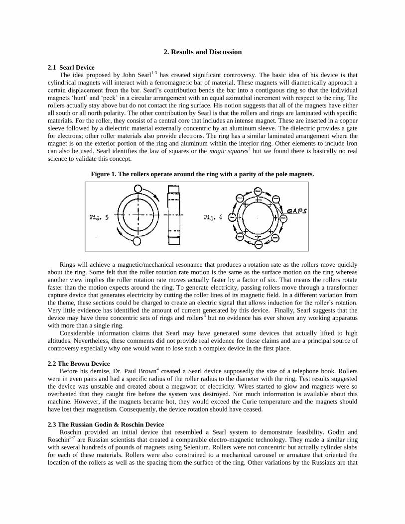
Figure 1. The rollers operate around the ring with a parity of the pole magnets.
Rings will achieve a magnetic/mechanical resonance that produces a rotation rate as the rollers move quickly
about the ring. Some felt that the roller rotation rate motion is the same as the surface motion on the ring whereas
another view implies the roller rotation rate moves actually faster by a factor of six. That means the rollers rotate
faster than the motion expects around the ring. To generate electricity, passing rollers move through a transformer
capture device that generates electricity by cutting the roller lines of its magnetic field. In a different variation from
the theme, these sections could be charged to create an electric signal that allows induction for the roller’s rotation.
Very little evidence has identified the amount of current generated by this device. Finally, Searl suggests that the
device may have three concentric sets of rings and rollers3 but no evidence has ever shown any working apparatus
with more than a single ring.
Considerable information claims that Searl may have generated some devices that actually lifted to high
altitudes. Nevertheless, these comments did not provide real evidence for these claims and are a principal source of
controversy especially why one would want to lose such a complex device in the first place.
2.2 The Brown Device
Before his demise, Dr. Paul Brown4 created a Searl device supposedly the size of a telephone book. Rollers
were in even pairs and had a specific radius of the roller radius to the diameter with the ring. Test results suggested
the device was unstable and created about a megawatt of electricity. Wires started to glow and magnets were so
overheated that they caught fire before the system was destroyed. Not much information is available about this
machine. However, if the magnets became hot, they would exceed the Curie temperature and the magnets should
have lost their magnetism. Consequently, the device rotation should have ceased.
2.3 The Russian Godin & Roschin Device
Roschin provided an initial device that resembled a Searl system to demonstrate feasibility. Godin and
Roschin5-7
are Russian scientists that created a comparable electro-magnetic technology. They made a similar ring
with several hundreds of pounds of magnets using Selenium. Rollers were not concentric but actually cylinder slabs
for each of these materials. Rollers were also constrained to a mechanical carousel or armature that oriented the
location of the rollers as well as the spacing from the surface of the ring. Other variations by the Russians are that
the rollers had used radial magnets meshed between the rollers and the ring. If this worked successfully, rollers
would rotate per the linear spacing of the ring where the magnets meshed like gear teeth.
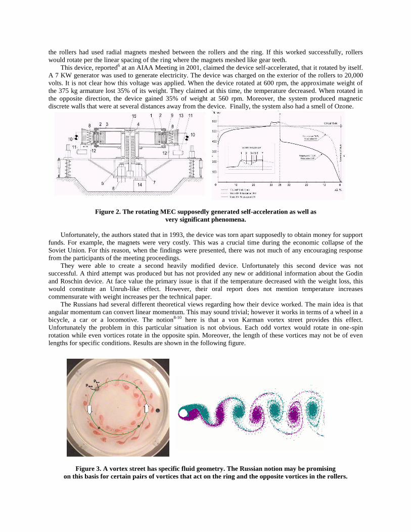
This device, reported6 at an AIAA Meeting in 2001, claimed the device self-accelerated, that it rotated by itself.
A 7 KW generator was used to generate electricity. The device was charged on the exterior of the rollers to 20,000
volts. It is not clear how this voltage was applied. When the device rotated at 600 rpm, the approximate weight of
the 375 kg armature lost 35% of its weight. They claimed at this time, the temperature decreased. When rotated in
the opposite direction, the device gained 35% of weight at 560 rpm. Moreover, the system produced magnetic
discrete walls that were at several distances away from the device. Finally, the system also had a smell of Ozone.
Figure 2. The rotating MEC supposedly generated self-acceleration as well as
very significant phenomena.
Unfortunately, the authors stated that in 1993, the device was torn apart supposedly to obtain money for support
funds. For example, the magnets were very costly. This was a crucial time during the economic collapse of the
Soviet Union. For this reason, when the findings were presented, there was not much of any encouraging response
from the participants of the meeting proceedings.
They were able to create a second heavily modified device. Unfortunately this second device was not
successful. A third attempt was produced but has not provided any new or additional information about the Godin
and Roschin device. At face value the primary issue is that if the temperature decreased with the weight loss, this
would constitute an Unruh-like effect. However, their oral report does not mention temperature increases
commensurate with weight increases per the technical paper.
The Russians had several different theoretical views regarding how their device worked. The main idea is that
angular momentum can convert linear momentum. This may sound trivial; however it works in terms of a wheel in a
bicycle, a car or a locomotive. The notion8-10
here is that a von Karman vortex street provides this effect.
Unfortunately the problem in this particular situation is not obvious. Each odd vortex would rotate in one-spin
rotation while even vortices rotate in the opposite spin. Moreover, the length of these vortices may not be of even
lengths for specific conditions. Results are shown in the following figure.
Figure 3. A vortex street has specific fluid geometry. The Russian notion may be promising
on this basis for certain pairs of vortices that act on the ring and the opposite vortices in the rollers.
2.4 The Morningstar Energy Box
The name “Energy Box” is definitely a misnomer. The original purpose of the device was to originally create a
magnetic motion drive. Unfortunately this did not occur when experiments revealed that the device could alter its
weight. This was unexpected. The unusual operation of this device is that the rollers move within a three-
dimensional magnetic field in a circular kinematic trajectory that differs from an axisymmetric electrical motor
because of the electromagnetic field trajectory.
This revolutionary variant is based upon at least three possible theoretical principles. These possibilities are:
Angular momentum- The idea is to change Mother Nature by transferring angular momentum into linear
momentum possibly similar to the Russian motives.
Gravito-Electro-Magnetism (GEM11
)- This notion uses a Poynting vector force induction based upon the
roller design that act like magnetic dipoles, and
Retarded Potentials- The ring acts as a roller reflection plane on the ring. If the time is retarded or through
magnetic hysteresis, it is possible that the image and subsequent forces from one roller may attract the
adjacent roller to create self-acceleration.
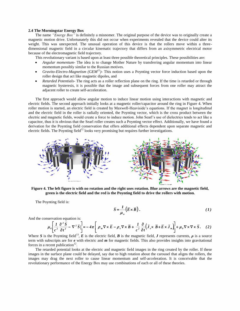
The first approach would allow angular motion to induce linear motion using interactions with magnetic and
electric fields. The second approach initially looks at a magnetic roller/capacitor around the ring in Figure 4. When
roller motion is started, an electric field is created by Maxwell-Heaviside’s equations. If the magnet is longitudinal
and the electric field in the roller is radially oriented, the Poynting vector, which is the cross product between the
electric and magnetic fields, would create a force to induce motion. John Searl’s use of dielectrics tends to act like a
capacitor, thus it is obvious that the Searl roller creates such a Poynting vector effect. Additionally, we have found a
derivation for the Poynting field conservation that offers additional effects dependent upon separate magnetic and
electric fields. The Poynting field12
looks very promising but requires further investigations.
Figure 4. The left figure is with no rotation and the right uses rotation. Blue arrows are the magnetic field,
green is the electric field and the red is the Poynting field to drive the rollers with motion.
The Poynting field is:
)1(.BE1
So
And the conservation equation is:
)2(.SJEBJtc
1BE4S
t
S
c
10me2em
2
2
2
20
Where S is the Poynting field13
, E is the electric field, B is the magnetic field, J represents currents, ρ is a source
term with subscripts are for e with electric and m for magnetic fields. This also provides insights into gravitational
forces in a recent publication12
.
The retarded potential looks at the electric and magnetic field images in the ring created by the roller. If these
images in the surface plane could be delayed, say due to high rotation about the carousel that aligns the rollers, the
images may drag the next roller to cause linear momentum and self-acceleration. It is conceivable that the
revolutionary performance of the Energy Box may use combinations of each or all of these theories.
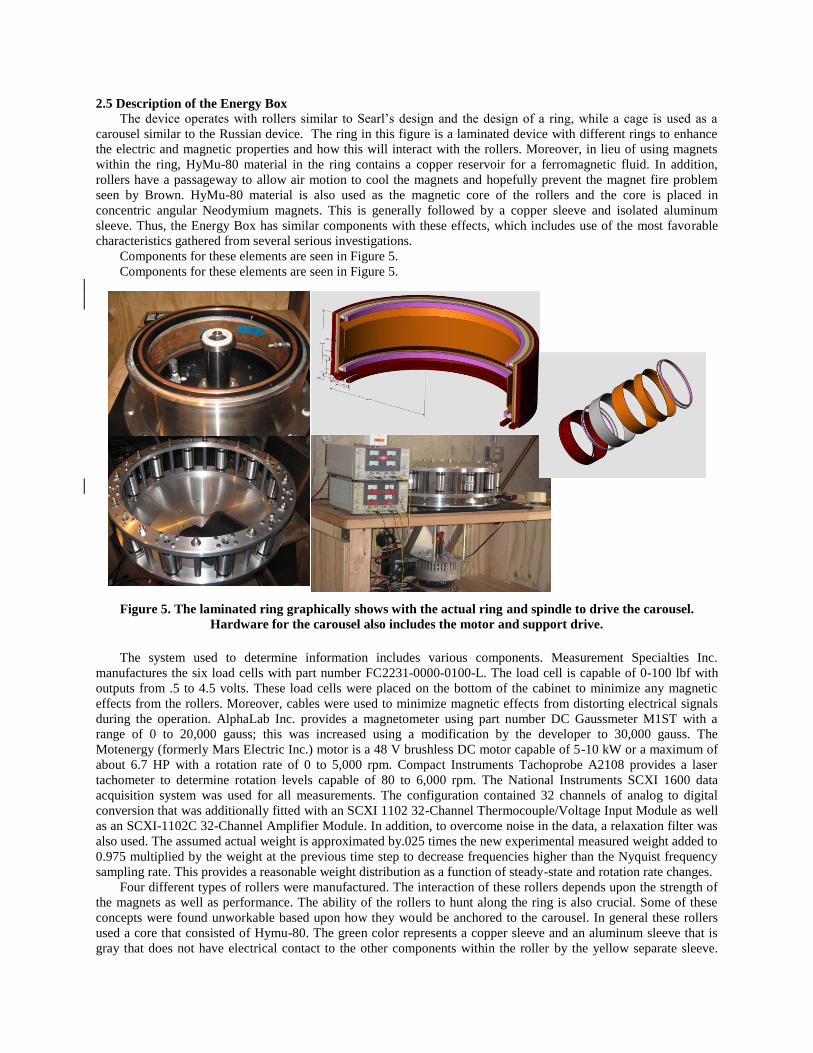
2.5 Description of the Energy Box
The device operates with rollers similar to Searl’s design and the design of a ring, while a cage is used as a
carousel similar to the Russian device. The ring in this figure is a laminated device with different rings to enhance
the electric and magnetic properties and how this will interact with the rollers. Moreover, in lieu of using magnets
within the ring, HyMu-80 material in the ring contains a copper reservoir for a ferromagnetic fluid. In addition,
rollers have a passageway to allow air motion to cool the magnets and hopefully prevent the magnet fire problem
seen by Brown. HyMu-80 material is also used as the magnetic core of the rollers and the core is placed in
concentric angular Neodymium magnets. This is generally followed by a copper sleeve and isolated aluminum
sleeve. Thus, the Energy Box has similar components with these effects, which includes use of the most favorable
characteristics gathered from several serious investigations.
Components for these elements are seen in Figure 5.
Components for these elements are seen in Figure 5.
Figure 5. The laminated ring graphically shows with the actual ring and spindle to drive the carousel.
Hardware for the carousel also includes the motor and support drive.
The system used to determine information includes various components. Measurement Specialties Inc.
manufactures the six load cells with part number FC2231-0000-0100-L. The load cell is capable of 0-100 lbf with
outputs from .5 to 4.5 volts. These load cells were placed on the bottom of the cabinet to minimize any magnetic
effects from the rollers. Moreover, cables were used to minimize magnetic effects from distorting electrical signals
during the operation. AlphaLab Inc. provides a magnetometer using part number DC Gaussmeter M1ST with a
range of 0 to 20,000 gauss; this was increased using a modification by the developer to 30,000 gauss. The
Motenergy (formerly Mars Electric Inc.) motor is a 48 V brushless DC motor capable of 5-10 kW or a maximum of
about 6.7 HP with a rotation rate of 0 to 5,000 rpm. Compact Instruments Tachoprobe A2108 provides a laser
tachometer to determine rotation levels capable of 80 to 6,000 rpm. The National Instruments SCXI 1600 data
acquisition system was used for all measurements. The configuration contained 32 channels of analog to digital
conversion that was additionally fitted with an SCXI 1102 32-Channel Thermocouple/Voltage Input Module as well
as an SCXI-1102C 32-Channel Amplifier Module. In addition, to overcome noise in the data, a relaxation filter was
also used. The assumed actual weight is approximated by.025 times the new experimental measured weight added to
0.975 multiplied by the weight at the previous time step to decrease frequencies higher than the Nyquist frequency
sampling rate. This provides a reasonable weight distribution as a function of steady-state and rotation rate changes.
Four different types of rollers were manufactured. The interaction of these rollers depends upon the strength of
the magnets as well as performance. The ability of the rollers to hunt along the ring is also crucial. Some of these
concepts were found unworkable based upon how they would be anchored to the carousel. In general these rollers
used a core that consisted of Hymu-80. The green color represents a copper sleeve and an aluminum sleeve that is
gray that does not have electrical contact to the other components within the roller by the yellow separate sleeve.
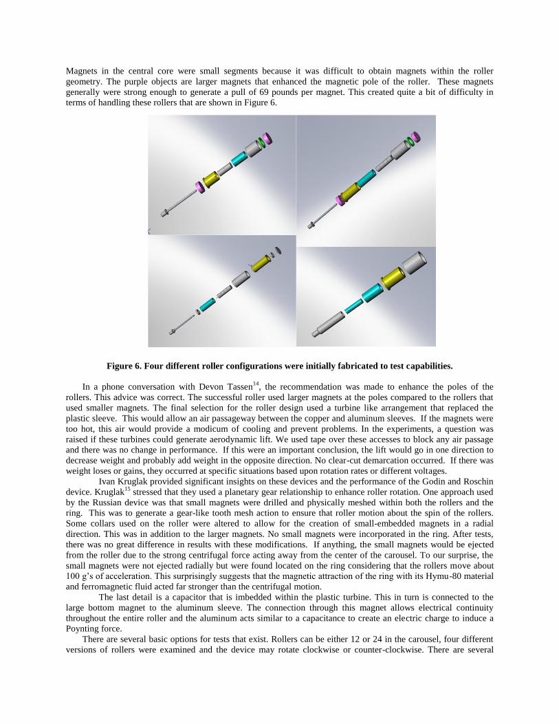
Magnets in the central core were small segments because it was difficult to obtain magnets within the roller
geometry. The purple objects are larger magnets that enhanced the magnetic pole of the roller. These magnets
generally were strong enough to generate a pull of 69 pounds per magnet. This created quite a bit of difficulty in
terms of handling these rollers that are shown in Figure 6.
Figure 6. Four different roller configurations were initially fabricated to test capabilities.
In a phone conversation with Devon Tassen14
, the recommendation was made to enhance the poles of the
rollers. This advice was correct. The successful roller used larger magnets at the poles compared to the rollers that
used smaller magnets. The final selection for the roller design used a turbine like arrangement that replaced the
plastic sleeve. This would allow an air passageway between the copper and aluminum sleeves. If the magnets were
too hot, this air would provide a modicum of cooling and prevent problems. In the experiments, a question was
raised if these turbines could generate aerodynamic lift. We used tape over these accesses to block any air passage
and there was no change in performance. If this were an important conclusion, the lift would go in one direction to
decrease weight and probably add weight in the opposite direction. No clear-cut demarcation occurred. If there was
weight loses or gains, they occurred at specific situations based upon rotation rates or different voltages.
Ivan Kruglak provided significant insights on these devices and the performance of the Godin and Roschin
device. Kruglak15
stressed that they used a planetary gear relationship to enhance roller rotation. One approach used
by the Russian device was that small magnets were drilled and physically meshed within both the rollers and the
ring. This was to generate a gear-like tooth mesh action to ensure that roller motion about the spin of the rollers.
Some collars used on the roller were altered to allow for the creation of small-embedded magnets in a radial
direction. This was in addition to the larger magnets. No small magnets were incorporated in the ring. After tests,
there was no great difference in results with these modifications. If anything, the small magnets would be ejected
from the roller due to the strong centrifugal force acting away from the center of the carousel. To our surprise, the
small magnets were not ejected radially but were found located on the ring considering that the rollers move about
100 g’s of acceleration. This surprisingly suggests that the magnetic attraction of the ring with its Hymu-80 material
and ferromagnetic fluid acted far stronger than the centrifugal motion.
The last detail is a capacitor that is imbedded within the plastic turbine. This in turn is connected to the
large bottom magnet to the aluminum sleeve. The connection through this magnet allows electrical continuity
throughout the entire roller and the aluminum acts similar to a capacitance to create an electric charge to induce a
Poynting force.
There are several basic options for tests that exist. Rollers can be either 12 or 24 in the carousel, four different
versions of rollers were examined and the device may rotate clockwise or counter-clockwise. There are several
different voltages usually from 0, 60, 120, 180 and 1,000 voltages with plus or minus charges and the amount of
ferromagnetic fluid can be at 0, .50, to 1.00 levels. This easily results in a spectrum of at least 120 test variations.
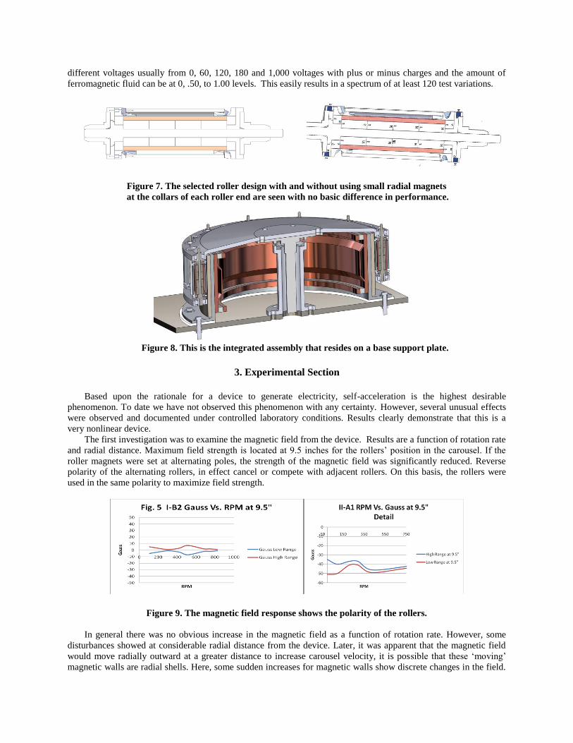
Figure 7. The selected roller design with and without using small radial magnets
at the collars of each roller end are seen with no basic difference in performance.
Figure 8. This is the integrated assembly that resides on a base support plate.
3. Experimental Section
Based upon the rationale for a device to generate electricity, self-acceleration is the highest desirable
phenomenon. To date we have not observed this phenomenon with any certainty. However, several unusual effects
were observed and documented under controlled laboratory conditions. Results clearly demonstrate that this is a
very nonlinear device.
The first investigation was to examine the magnetic field from the device. Results are a function of rotation rate
and radial distance. Maximum field strength is located at 9.5 inches for the rollers’ position in the carousel. If the
roller magnets were set at alternating poles, the strength of the magnetic field was significantly reduced. Reverse
polarity of the alternating rollers, in effect cancel or compete with adjacent rollers. On this basis, the rollers were
used in the same polarity to maximize field strength.
Figure 9. The magnetic field response shows the polarity of the rollers.
In general there was no obvious increase in the magnetic field as a function of rotation rate. However, some
disturbances showed at considerable radial distance from the device. Later, it was apparent that the magnetic field
would move radially outward at a greater distance to increase carousel velocity, it is possible that these ‘moving’
magnetic walls are radial shells. Here, some sudden increases for magnetic walls show discrete changes in the field.
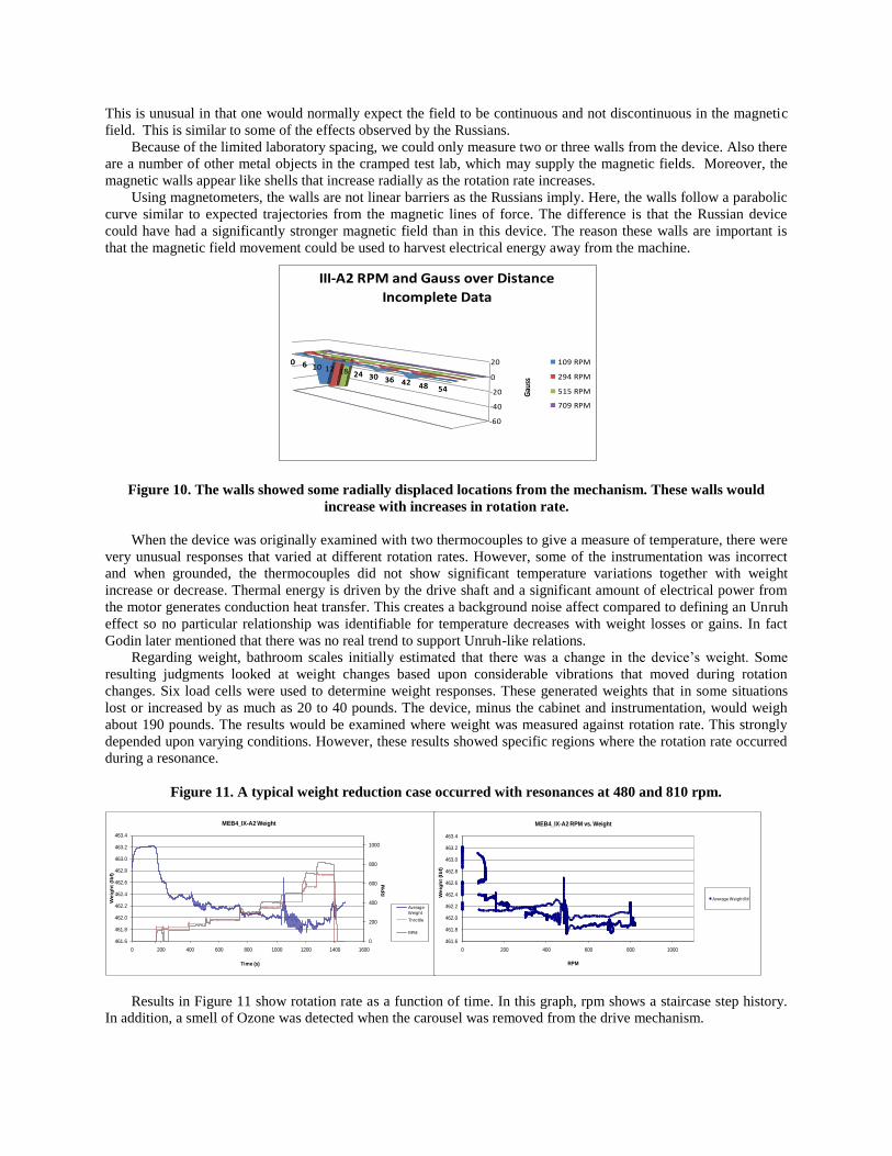
This is unusual in that one would normally expect the field to be continuous and not discontinuous in the magnetic
field. This is similar to some of the effects observed by the Russians.
Because of the limited laboratory spacing, we could only measure two or three walls from the device. Also there
are a number of other metal objects in the cramped test lab, which may supply the magnetic fields. Moreover, the
magnetic walls appear like shells that increase radially as the rotation rate increases.
Using magnetometers, the walls are not linear barriers as the Russians imply. Here, the walls follow a parabolic
curve similar to expected trajectories from the magnetic lines of force. The difference is that the Russian device
could have had a significantly stronger magnetic field than in this device. The reason these walls are important is
that the magnetic field movement could be used to harvest electrical energy away from the machine.
Figure 10. The walls showed some radially displaced locations from the mechanism. These walls would
increase with increases in rotation rate.
When the device was originally examined with two thermocouples to give a measure of temperature, there were
very unusual responses that varied at different rotation rates. However, some of the instrumentation was incorrect
and when grounded, the thermocouples did not show significant temperature variations together with weight
increase or decrease. Thermal energy is driven by the drive shaft and a significant amount of electrical power from
the motor generates conduction heat transfer. This creates a background noise affect compared to defining an Unruh
effect so no particular relationship was identifiable for temperature decreases with weight losses or gains. In fact
Godin later mentioned that there was no real trend to support Unruh-like relations.
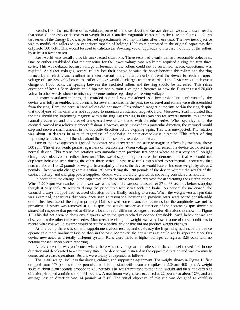
Regarding weight, bathroom scales initially estimated that there was a change in the device’s weight. Some
resulting judgments looked at weight changes based upon considerable vibrations that moved during rotation
changes. Six load cells were used to determine weight responses. These generated weights that in some situations
lost or increased by as much as 20 to 40 pounds. The device, minus the cabinet and instrumentation, would weigh
about 190 pounds. The results would be examined where weight was measured against rotation rate. This strongly
depended upon varying conditions. However, these results showed specific regions where the rotation rate occurred
during a resonance.
Figure 11. A typical weight reduction case occurred with resonances at 480 and 810 rpm.
Results in Figure 11 show rotation rate as a function of time. In this graph, rpm shows a staircase step history.
In addition, a smell of Ozone was detected when the carousel was removed from the drive mechanism.
0 6 10 12 18 24 30 36 42 48 54
-60
-40
-20
0
20
Gau
ss
0 6 10 12 18 24 30 36 42 48 54
III-A2 RPM and Gauss over Distance
Incomplete Data
109 RPM
294 RPM
515 RPM
709 RPM
0
200
400
600
800
1000
461.6
461.8
462.0
462.2
462.4
462.6
462.8
463.0
463.2
463.4
0 200 400 600 800 1000 1200 1400 1600
RP
M
Weig
ht
(lb
f)
Time (s)
MEB4_IX-A2 Weight
Average
Weight
Throttle
RPM
461.6
461.8
462.0
462.2
462.4
462.6
462.8
463.0
463.2
463.4
0 200 400 600 800 1000
Weig
ht
(lb
f)
RPM
MEB4_IX-A2 RPM vs. Weight
Average Weight lbf
Results from the first three series validated some of the ideas about the Russian device; we saw unusual results
that showed increases or decreases in weight but at a smaller magnitude compared to the Russian claims. A fourth
test series of the Energy Box was performed approximately two months later after these tests. The new test objective
was to modify the rollers to use capacitors capable of holding 1500 volts compared to the original capacitors that
only held 100 volts. This would be used to validate the Poynting vector approach to increase the force of the rollers
by at least a factor of ten.
Real world tests usually provide unexpected situations. These tests had clearly defined reasonable objectives.
One co-author established that the capacitor for the lower voltage was really not required during the first three
series. This was debated because voltage differences in the rollers could not be sustained; hence, capacitance was
required. At higher voltages, several rollers lost their charge because the space between the rollers and the ring
formed by an electric arc resulting in a short circuit. This limitation only allowed the device to reach an upper
voltage of, say 325 volts before the roller voltage would discharge. In other words, if the device was to achieve a
charge of 1,000 volts, the spacing between the insolated rollers and the ring should be increased. This raises
questions of how a Searl device could operate and sustain a voltage difference or how the Russians used 20,000
volts? In other words, short circuits may become routine regarding conserving voltage.
In many postulated theories, the retarded potential was considered as a low probability. Unfortunately, the
device was fully assembled and dormant for several months. In the past, the carousel and rollers were disassembled
from the ring. Here, the carousel and rollers did not move. This induced magnetic imprints within the ring despite
that the Hymu-80 material was not supposed to maintain a sustained magnetic field. Moreover, Searl indicated that
the ring should use imprinting magnets within the ring. By residing in this position for several months, this imprint
naturally occurred and this created unexpected events compared with the other series. When spun by hand, the
carousel coasted in a relatively smooth fashion. However, after it moved in a particular direction, the carousel would
stop and move a small amount in the opposite direction before stopping again. This was unexpected. The rotation
was about 10 degrees in azimuth regardless of clockwise or counter-clockwise direction. This effect of ring
imprinting tends to support the idea about the hypothesis for a retarded potential.
One of the investigators suggested the device would overcome the strange magnetic effects by rotations above
300 rpm. This effect would persist regardless of rotation rate. When voltage was increased, the device would act as a
normal device. This meant that rotation was smoother than previous test series where only a very small weight
change was observed in either direction. This was disappointing because this demonstrated that we could not
duplicate behavior seen during the other three series. These new trials established experimental uncertainty that
reached about .1 or .2 pounds of weight. In a majority of runs, the device would lose or increase weight by about 2
pounds. These weight changes were within 1% considering the 190 pounds of the device without the weight of the
cabinet, battery, and charging power supplies. Results were therefore ignored as not being considered as notable.
In addition to the change in the capacitors, the brake drive was also removed for decelerating the electric motor.
When 1,000 rpm was reached and power was withdrawn, the carousel coasted for 37 to 39 seconds before stopping
though it only took 20 seconds during the prior three test series with the brake. As previously mentioned, the
carousel always stopped and reversed direction before finally coming to a rest. When the weight versus rpm data
was examined, departures that were once seen at resonance locations in previous tests were found considerably
diminished because of the ring imprinting. Data showed some resonance locations but the amplitude was not as
prevalent. If power was removed at 1,000 rpm, the weight history as a function of the decreasing rpm showed a
sinusoidal response that peaked at different locations for different voltages or rotation directions as shown in Figure
12. This did not seem to show any disparity when the rpm reached resonance thresholds. Such behavior was not
observed for the other three test series. Moreover, the change in weight was very low at some of these conditions to
record what you would assume would occur for a normal device that did not produce weight changes.
At this point, there was some disappointment about results, and obviously the imprinting had made the device
operate in a more nonlinear fashion than in the past. Moreover, the earlier results could not be repeated since this
device now acted as a totally different system. Runs were made at higher voltages as high as 325 volts with no
notable consequences worth reporting.
A reference trial was performed where there was no voltage at the rollers and the carousel moved first in one
direction and decelerated to a stationary state. The device was restarted in the opposite direction and was eventually
decreased to cease operations. Results were totally unexpected as follows.
The initial weight includes the device, cabinet, and supporting equipment. The weight shown in Figure 13 first
dropped from 447 pounds to 433 pounds, and held constant with resonance spikes at 220 and 400 rpm. A weight
spike at about 2180 seconds dropped to 425 pounds. The weight returned to the initial weight and then, at a different
direction, dropped a minimum of 431 pounds. A maximum weight loss occurred at 22 pounds at about 12%, and an
average loss in direction was 14 pounds at 7.3%. The initial objective of this run was designed to establish
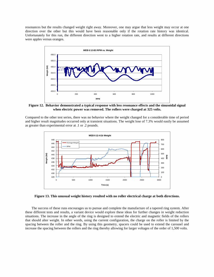
resonances but the results changed weight right away. Moreover, one may argue that less weight may occur at one
direction over the other but this would have been reasonable only if the rotation rate history was identical.
Unfortunately for this run, the different direction went to a higher rotation rate, and results at different directions
were apples versus oranges.
433.0
433.5
434.0
434.5
435.0
435.5
436.0
0 200 400 600 800 1000
Weig
ht
(lb
f)
RPM
MEB 6 12-B3 RPM vs. Weight
Figure 12. Behavior demonstrated a typical response with less resonance effects and the sinusoidal signal
when electric power was removed. The rollers were charged at 325 volts.
Compared to the other test series, there was no behavior where the weight changed for a considerable time of period
and higher result magnitudes occurred only at transient situations. The weight lose of 7.3% would easily be assumed
as greater than experimental error at .1 or .2 pounds.
0
100
200
300
400
500
600
700
800
428
430
432
434
436
438
440
442
444
446
448
0 500 1000 1500 2000 2500 3000
RP
M
Weig
ht
(lb
f)
Time (s)
MEB 6 12-A1b Weight
Average Weight
RPM
Figure 13. This unusual weight history resulted with no roller electrical charge at both directions.
The success of these runs encourages us to pursue and complete the manufacture of a tapered ring system. After
these different tests and results, a variant device would explore these ideas for further changes in weight reduction
situations. The increase in the angle of the ring is designed to extend the electric and magnetic fields of the rollers
that should alter weight. In other words, using the current configuration, the charge on the roller is limited by the
spacing between the roller and the ring. By using this geometry, spacers could be used to extend the carousel and
increase the spacing between the rollers and the ring thereby allowing for larger voltages of the order of 1,500 volts.
420
425
430
435
440
445
450
0 100 200 300 400 500 600 700 800
Weig
ht
(lb
f)
RPM
MEB 6 12-A1b RPM vs. Weight
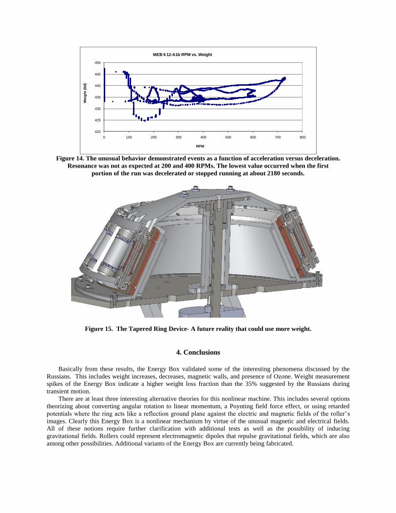
Figure 14. The unusual behavior demonstrated events as a function of acceleration versus deceleration.
Resonance was not as expected at 200 and 400 RPMs. The lowest value occurred when the first
portion of the run was decelerated or stopped running at about 2180 seconds.
Figure 15. The Tapered Ring Device- A future reality that could use more weight.
4. Conclusions
Basically from these results, the Energy Box validated some of the interesting phenomena discussed by the
Russians. This includes weight increases, decreases, magnetic walls, and presence of Ozone. Weight measurement
spikes of the Energy Box indicate a higher weight loss fraction than the 35% suggested by the Russians during
transient motion.
There are at least three interesting alternative theories for this nonlinear machine. This includes several options
theorizing about converting angular rotation to linear momentum, a Poynting field force effect, or using retarded
potentials where the ring acts like a reflection ground plane against the electric and magnetic fields of the roller’s
images. Clearly this Energy Box is a nonlinear mechanism by virtue of the unusual magnetic and electrical fields.
All of these notions require further clarification with additional tests as well as the possibility of inducing
gravitational fields. Rollers could represent electromagnetic dipoles that repulse gravitational fields, which are also
among other possibilities. Additional variants of the Energy Box are currently being fabricated.
References
[1]
Thomas, J., ANTIGRAVITY: The Dream Made Reality, the Story of John Searl (1993). [2] LaViolette, P. A., “How the Searl Effect Works: Analysis of the Magnetic Energy Converter”, June 17, 2001.
[3] Sandberg, S. Gunnar: “The Searl-Effect Generator- Design and Manufacturing Procedure”, School of Engineering and
Applied Sciences, University of Sussex, SEG-003 and SEG-004, March 1986.
[4]
Paul Brown’s Notebook on Searl’s Device.
[5] Godin, S. M. and Roschin, V. V. in the USSR. “Orbiting Multi-Rotor Homopolar System”, A US Patent 6.822,361 for this
device held by Energy and Propulsion Systems, Nov. 2004, Valencia CA.00
[6] Roschin, V. V. and Godin, S. M., “An Experimental Investigation of the Physical Effects in a Dynamic Magnetic System”,
AIAA Paper 2001-3660, 2001.
[7] Roschin, V. V. and Godin, S. M., “An Experimental Investigation of the Physical Effects in a Dynamic Magnetic System”,
Technical Letters, Vol. 26, No. 12, 2000, pp. 1105-1107.
[8]
Karimov, A. R., Stenflo, L. and Yu, M. Y., Coupled flows and oscillations in asymmetric rotating plasmas, PHYSICS OF
PLASMAS 16, 102303, 2009.
[9]
Karimov, A. R., Stenflo, L. and Yu, M. Y., Coupled azimuthal and radial flows and oscillations in a rotating plasma,
PHYSICS OF PLASMAS 16, 062313, 2009, published online 29 June 2009.
[10]
Karimov, A. R., and Godin, S. M., Coupled radial–azimuthal oscillations in twirling cylindrical plasmas, IOP
PUBLISHING PHYSICA SCRIPTA, Phys. Scr. 80 (2009) 035503 (6pp) doi: 10.1088/0031-8949/80/03/035503, Published
25 August 2009.
[11] Brandenburg, J. E., “A Theoretical Value for the Newton Gravitation Constant from the GEM Theory of Field Unification
and the Kursunoglu-Brandenburg Hypothesis of Massive Gamma-Ray Bursters”, The Launching of La Belle Époque of
High Energy Physics and Cosmology, 2003 (pp 112-119).
[12] Murad, P. A. and Brandenburg, J. E., “The Murad-Brandenburg Equation- A Wave Partial Differential Expression for the
Poynting Vector/Field Conservation”, AIAA 50th Aerospace Science Meeting, AIAA Paper 2012-0997, Nashville,
Tennessee, Jan 9-12, 2012.
[13] Lorentz, H. A., Weyl, H. and Minkowski, H., Einstein: The Principle of Relativity, Dover Publications, Inc. 1952.
[14] Private conversations with Devon Tassen.
[15] Private conversations with Ivan Kruglak at a technical meeting.