The EVLA Project - NRAO: Socorro, New Mexico · •1 μJy point-source continuum sensitivity (most...
14
Eleventh Synthesis Imaging Workshop Socorro, June 10-17, 2008 The EVLA Project Rick Perley National Radio Astronomy Observatory
Transcript of The EVLA Project - NRAO: Socorro, New Mexico · •1 μJy point-source continuum sensitivity (most...
Eleventh Synthesis Imaging WorkshopSocorro, June 10-17, 2008
The EVLA Project
Rick PerleyNational Radio Astronomy Observatory

2
Eleventh Synthesis Imaging Workshop, June 10-17, 2008
EVLA Project Goals
• Fundamental Goal: By building on the existing infrastructure, multiply ten-fold the VLA’s observational capabilities.
• Full frequency coverage from 1 to 50 GHz.– 8 frequency bands with cryogenic receivers.– Two independent simultaneously available frequency pairs, with no
tuning restrictions. • 1 μJy point-source continuum sensitivity (most bands)• New correlator with 8 GHz/polarization capability
– 16384 minimum channels/baseline, with full polarization. – Full recirculation capability for expanded frequency resolution.– 128 independently digitally tunable frequency slots.
• Noise-limited full-beam imaging in all Stokes parameters• Completion by 2012.
3
Eleventh Synthesis Imaging Workshop, June 10-17, 2008
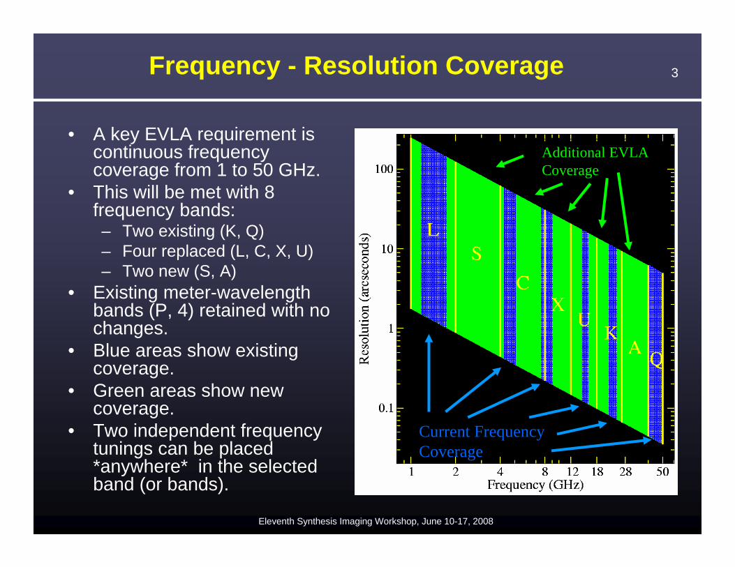
Frequency - Resolution Coverage
• A key EVLA requirement is continuous frequency coverage from 1 to 50 GHz.
• This will be met with 8 frequency bands:– Two existing (K, Q)– Four replaced (L, C, X, U)– Two new (S, A)
• Existing meter-wavelength bands (P, 4) retained with no changes.
• Blue areas show existing coverage.
• Green areas show new coverage.
• Two independent frequency tunings can be placed *anywhere* in the selected band (or bands).
Current Frequency Coverage
Additional EVLA Coverage
4
Eleventh Synthesis Imaging Workshop, June 10-17, 2008
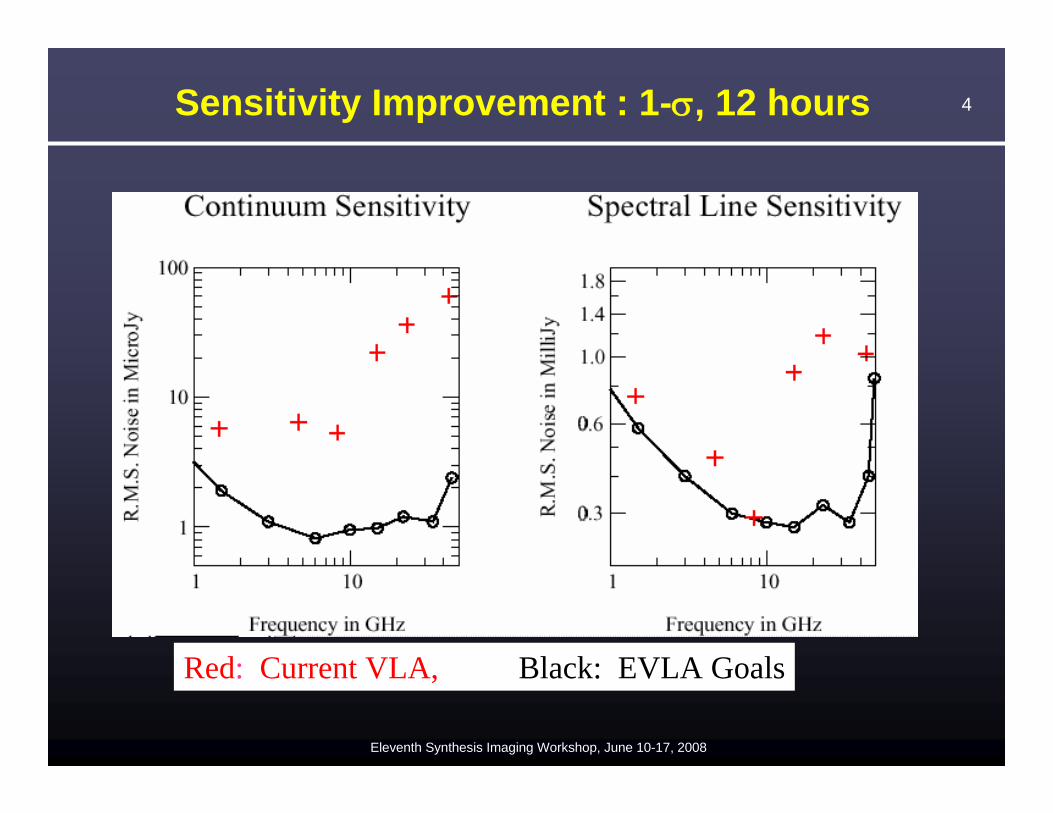
Sensitivity Improvement : 1-σ, 12 hours
Red: Current VLA, Black: EVLA Goals
5
Eleventh Synthesis Imaging Workshop, June 10-17, 2008
EVLA Performance Goals
100%
0.12 Hz2 MHz
4,194,304
16,3848 GHz
1 μJy
EVLA
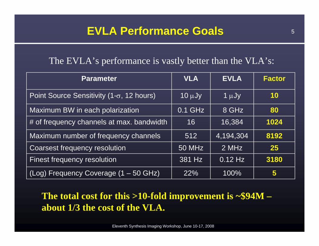
5 22%(Log) Frequency Coverage (1 – 50 GHz)
3180 381 HzFinest frequency resolution25 50 MHzCoarsest frequency resolution
8192 512Maximum number of frequency channels
1024 16# of frequency channels at max. bandwidth80 0.1 GHzMaximum BW in each polarization
10 10 μJyPoint Source Sensitivity (1-σ, 12 hours)
FactorVLAParameter
The EVLA’s performance is vastly better than the VLA’s:
The total cost for this >10-fold improvement is ~$94M –about 1/3 the cost of the VLA.
6
Eleventh Synthesis Imaging Workshop, June 10-17, 2008
What is the EVLA Not Doing?
• Expanding to provide 10 times the current best resolution (the New Mexico Array). – Lost: A ~few Kelvin brightness sensitivity at milliarcsecond
resolution capability provided by the full EVLA. • A super-compact configuration, for low surface
brightness imaging (the ‘E’ configuration). – This ~$6M component could easily and quickly be done as a
standalone project. (Lost: 10 μK brightness sensitivity on 12 arcsecond scale at 34 GHz).
• A sub-1 GHz facility. The VLA’s optics system makes it very difficult to implement an efficient wide-band low-frequency capability.– All proposed methods to do this require extensive design and
development – for which we have no budget.
7
Eleventh Synthesis Imaging Workshop, June 10-17, 2008
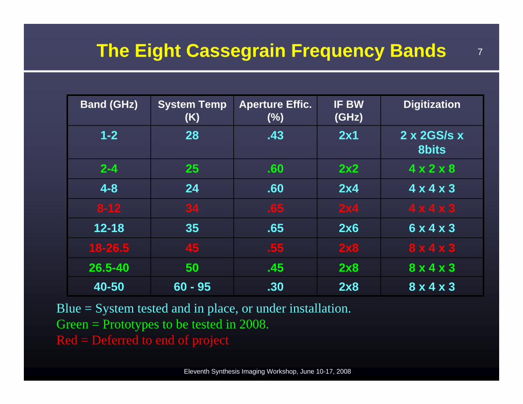
The Eight Cassegrain Frequency Bands
8 x 4 x 38 x 4 x 38 x 4 x 36 x 4 x 34 x 4 x 34 x 4 x 34 x 2 x 8
2 x 2GS/s x 8bits
Digitization
2x8.3060 - 9540-502x8.455026.5-402x8.554518-26.52x6.653512-182x4.65348-122x4.60244-82x2.60252-4
2x1.43281-2
IF BW (GHz)
Aperture Effic. (%)
System Temp (K)
Band (GHz)
Blue = System tested and in place, or under installation. Green = Prototypes to be tested in 2008.Red = Deferred to end of project
8
Eleventh Synthesis Imaging Workshop, June 10-17, 2008
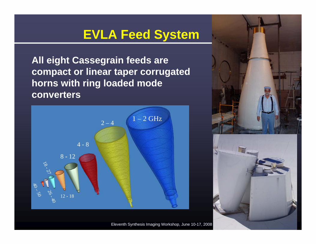
EVLA Feed System
All eight Cassegrain feeds are compact or linear taper corrugated horns with ring loaded mode converters
1 – 2 GHz2 – 4
4 - 8
8 - 12
12 - 18
18 - 2726 - 40
40 –50
9
Eleventh Synthesis Imaging Workshop, June 10-17, 2008
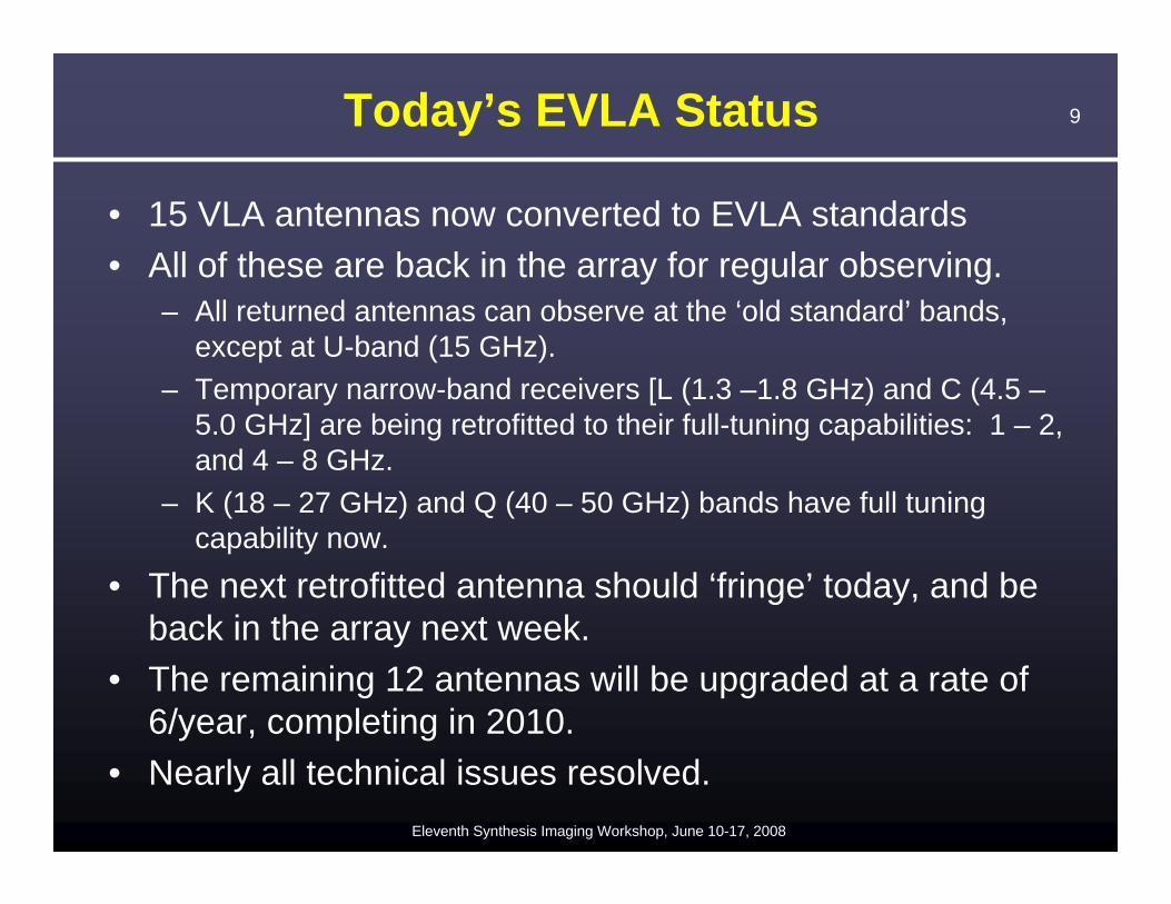
Today’s EVLA Status
• 15 VLA antennas now converted to EVLA standards• All of these are back in the array for regular observing.
– All returned antennas can observe at the ‘old standard’ bands, except at U-band (15 GHz).
– Temporary narrow-band receivers [L (1.3 –1.8 GHz) and C (4.5 –5.0 GHz] are being retrofitted to their full-tuning capabilities: 1 – 2, and 4 – 8 GHz.
– K (18 – 27 GHz) and Q (40 – 50 GHz) bands have full tuning capability now.
• The next retrofitted antenna should ‘fringe’ today, and be back in the array next week.
• The remaining 12 antennas will be upgraded at a rate of 6/year, completing in 2010.
• Nearly all technical issues resolved.
10
Eleventh Synthesis Imaging Workshop, June 10-17, 2008
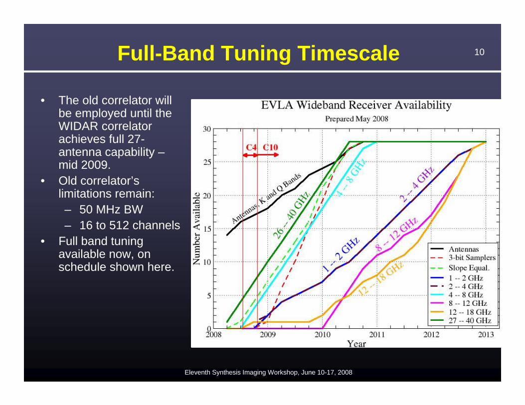
Full-Band Tuning Timescale
• The old correlator will be employed until the WIDAR correlator achieves full 27-antenna capability –mid 2009.
• Old correlator’slimitations remain:– 50 MHz BW– 16 to 512 channels
• Full band tuning available now, on schedule shown here.
11
Eleventh Synthesis Imaging Workshop, June 10-17, 2008
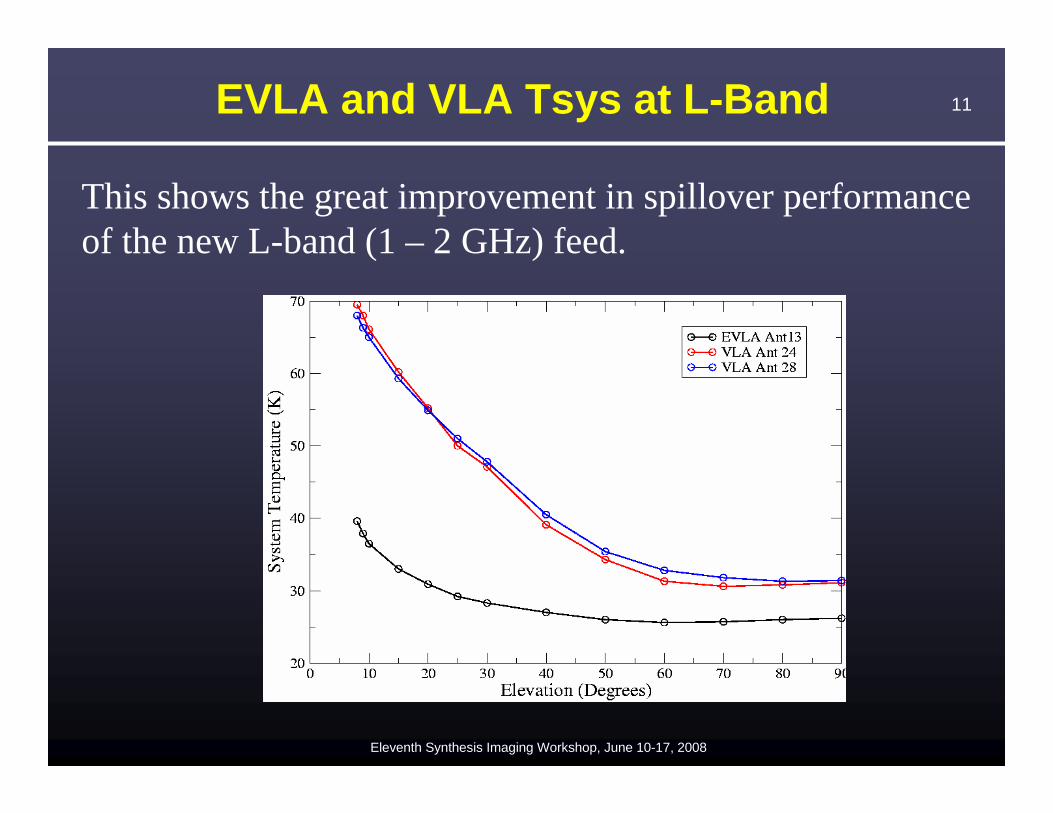
EVLA and VLA Tsys at L-Band
This shows the great improvement in spillover performanceof the new L-band (1 – 2 GHz) feed.
12
Eleventh Synthesis Imaging Workshop, June 10-17, 2008
WIDAR Correlator
• Design and construction of correlator by the DRAO correlator group (Penticton, BC, Canada).
• All costs covered by Canadian NRC.• WIDAR accepts 8 inputs, of up to 2 GHz BW each, normally
configured as four input (R,L) pairs. • Their design is an extraordinarily flexible machine allowing for
up to 64 independently defined (in frequency and bandwidth) sub-band pairs within the input bandwidth.
• Each digitally-defined sub-band pair has 256 channels, to be distributed amongst 1, 2, or 4 polarization products.
• Recirculation provided for increased frequency resolution.• Vast number of ways to share resources internally, trading
inputs, or sub-band pairs, or polarization, for more channels. • Full polarization, pulsar modes, phased array, VLBI-ready,
extensive subarraying, etc. • I have a (detailed) correlator document for those interested.
13
Eleventh Synthesis Imaging Workshop, June 10-17, 2008
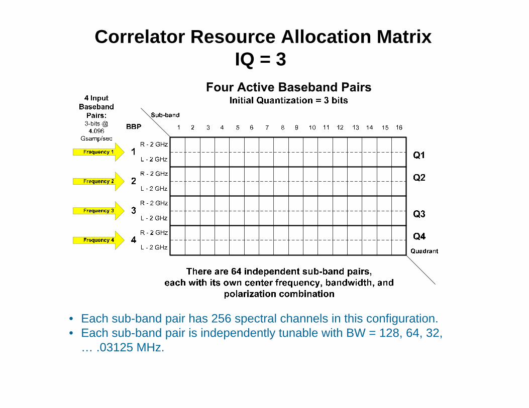
Correlator Resource Allocation MatrixIQ = 3
CRAM helps visualization of correlator resources.
• Each sub-band pair has 256 spectral channels in this configuration. • Each sub-band pair is independently tunable with BW = 128, 64, 32,
… .03125 MHz.
14
Eleventh Synthesis Imaging Workshop, June 10-17, 2008
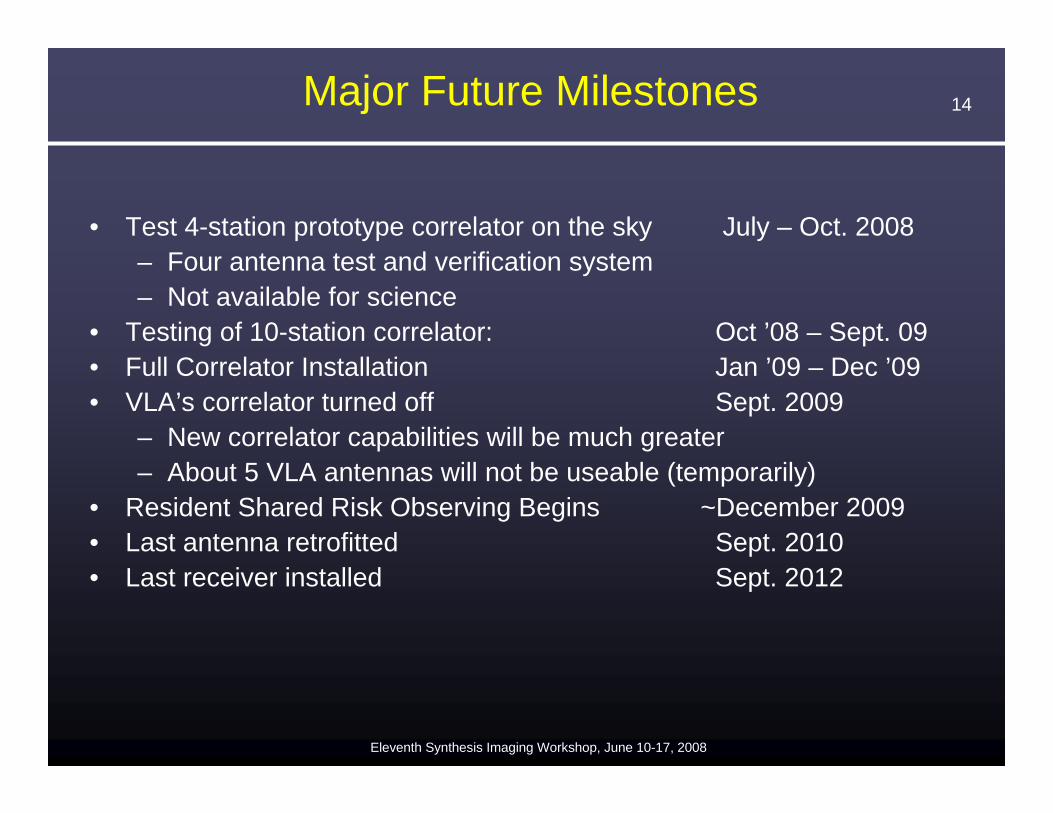
Major Future Milestones
• Test 4-station prototype correlator on the sky July – Oct. 2008– Four antenna test and verification system– Not available for science
• Testing of 10-station correlator: Oct ’08 – Sept. 09• Full Correlator Installation Jan ’09 – Dec ’09• VLA’s correlator turned off Sept. 2009
– New correlator capabilities will be much greater – About 5 VLA antennas will not be useable (temporarily)
• Resident Shared Risk Observing Begins ~December 2009• Last antenna retrofitted Sept. 2010• Last receiver installed Sept. 2012