E.T. Design Study Harald Lück. 3 main noise sources Thermal Noise Seismic Shot Noise.
The Effect of Correlated Level Shifting on
Noise Performance in Switched
Capacitor Circuits
Benjamin Hershberg, Tawfiq Musah,
Skyler Weaver, Un-Ku Moon
(Presented by Taehwan Oh)
School of Electrical Engineering and Computer Science
Oregon State University
Presentation Outline
• Background
– CLS (Correlated Level-Shifting)
– Split-CLS
• Theoretical Noise Analysis
• Numerical and Simulation Results
• Conclusion
Background
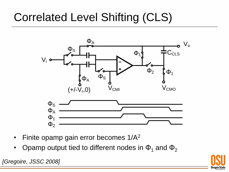
Correlated Level Shifting (CLS)
• Finite opamp gain error becomes 1/A2
• Opamp output tied to different nodes in Φ1 and Φ2
[Gregoire, JSSC 2008]
ФS
ФA
Ф1
Ф2
CCLS
VoФS
ФA
Ф1
Vi
ФA
Ф2
VCMI VCMO
ФS
Ф1
(+/-Vr,0)
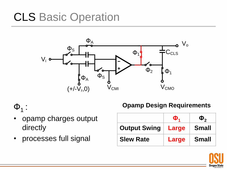
CLS Basic Operation
Ф1 :
• opamp charges output
directly
• processes full signal
Opamp Design Requirements
Ф1 Ф2
Output Swing Large Small
Slew Rate Large Small
CCLS
VoФS
ФA
Ф1
Vi
ФA
Ф2
VCMI VCMO
ФS
Ф1
(+/-Vr,0)
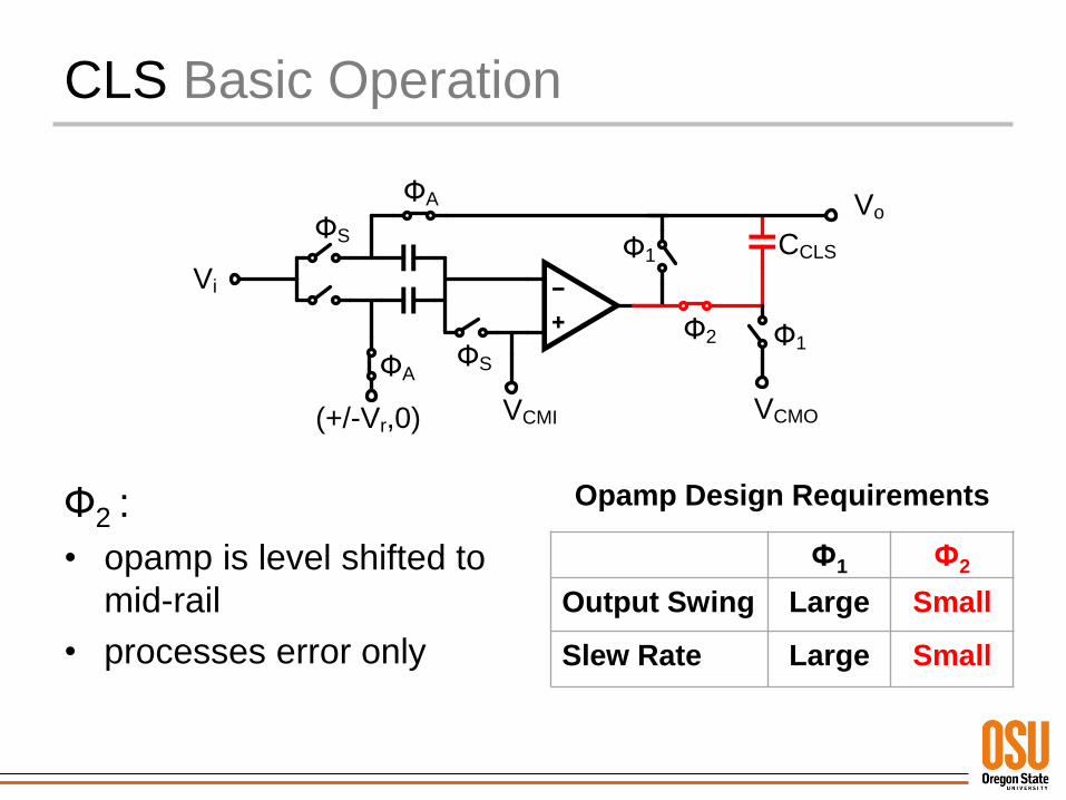
CLS Basic Operation
Ф2 :
• opamp is level shifted to
mid-rail
• processes error only
Opamp Design Requirements
Ф1 Ф2
Output Swing Large Small
Slew Rate Large Small
CCLS
VoФS
ФA
Ф1
Vi
ФA
Ф2
VCMI VCMO
ФS
Ф1
(+/-Vr,0)
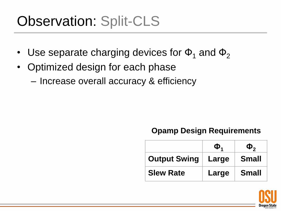
Observation: Split-CLS
• Use separate charging devices for Ф1 and Ф2
• Optimized design for each phase
– Increase overall accuracy & efficiency
Opamp Design Requirements
Ф1 Ф2
Output Swing Large Small
Slew Rate Large Small
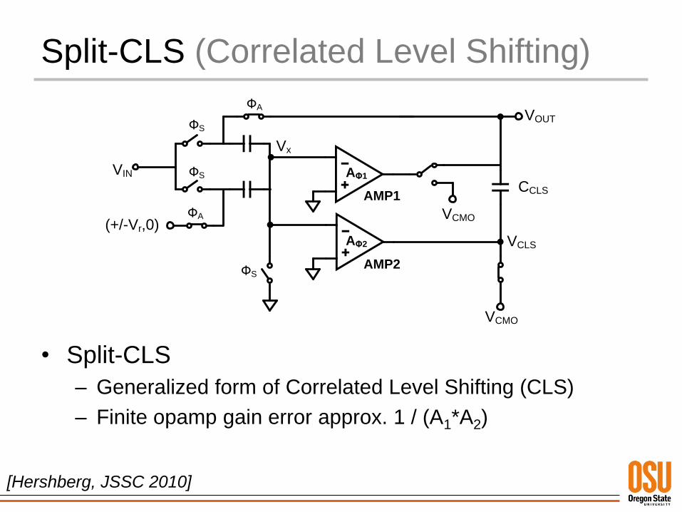
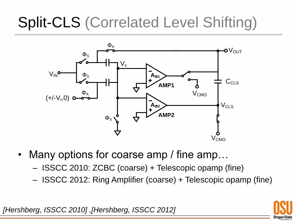
Split-CLS (Correlated Level Shifting)
• Split-CLS
– Generalized form of Correlated Level Shifting (CLS)
– Finite opamp gain error approx. 1 / (A1*A2)
CCLS
VOUTФS
ФA
VIN
ФA
VCMO
ФS
(+/-Vr,0)
AΦ1
AΦ2
Vx
VCLS
AMP1
AMP2
VCMO
ФS
[Hershberg, JSSC 2010]
Split-CLS (Correlated Level Shifting)
CCLS
VOUTФS
ФA
VIN
ФA
VCMO
ФS
(+/-Vr,0)
AΦ1
AΦ2
Vx
VCLS
AMP1
AMP2
VCMO
ФS
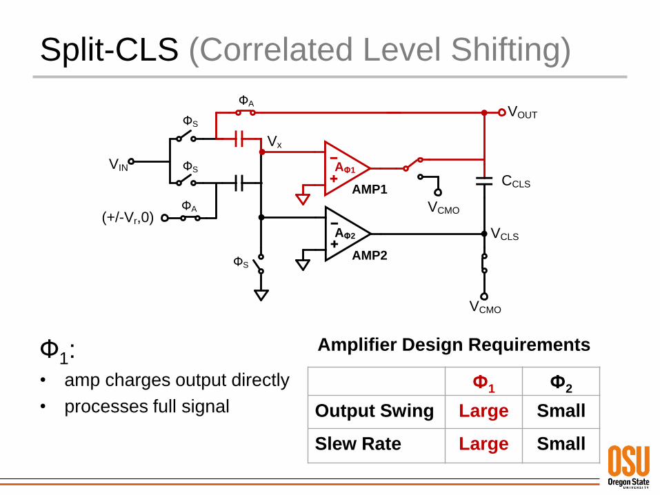
Ф1:• amp charges output directly
• processes full signal
Amplifier Design Requirements
Ф1 Ф2
Output Swing Large Small
Slew Rate Large Small
Split-CLS (Correlated Level Shifting)
CCLS
VOUTФS
ФA
VIN
ФA
VCMO
ФS
(+/-Vr,0)
AΦ1
AΦ2
Vx
VCLS
AMP1
AMP2
VCMO
ФS
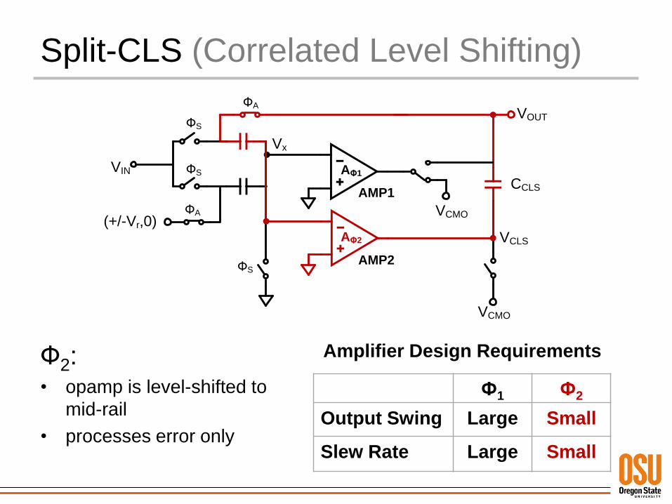
Ф2:• opamp is level-shifted to
mid-rail
• processes error only
Amplifier Design Requirements
Ф1 Ф2
Output Swing Large Small
Slew Rate Large Small
Split-CLS (Correlated Level Shifting)
• Many options for coarse amp / fine amp…– ISSCC 2010: ZCBC (coarse) + Telescopic opamp (fine)
– ISSCC 2012: Ring Amplifier (coarse) + Telescopic opamp (fine)
CCLS
VOUTФS
ФA
VIN
ФA
VCMO
ФS
(+/-Vr,0)
AΦ1
AΦ2
Vx
VCLS
AMP1
AMP2
VCMO
ФS
[Hershberg, ISSCC 2010] ,[Hershberg, ISSCC 2012]
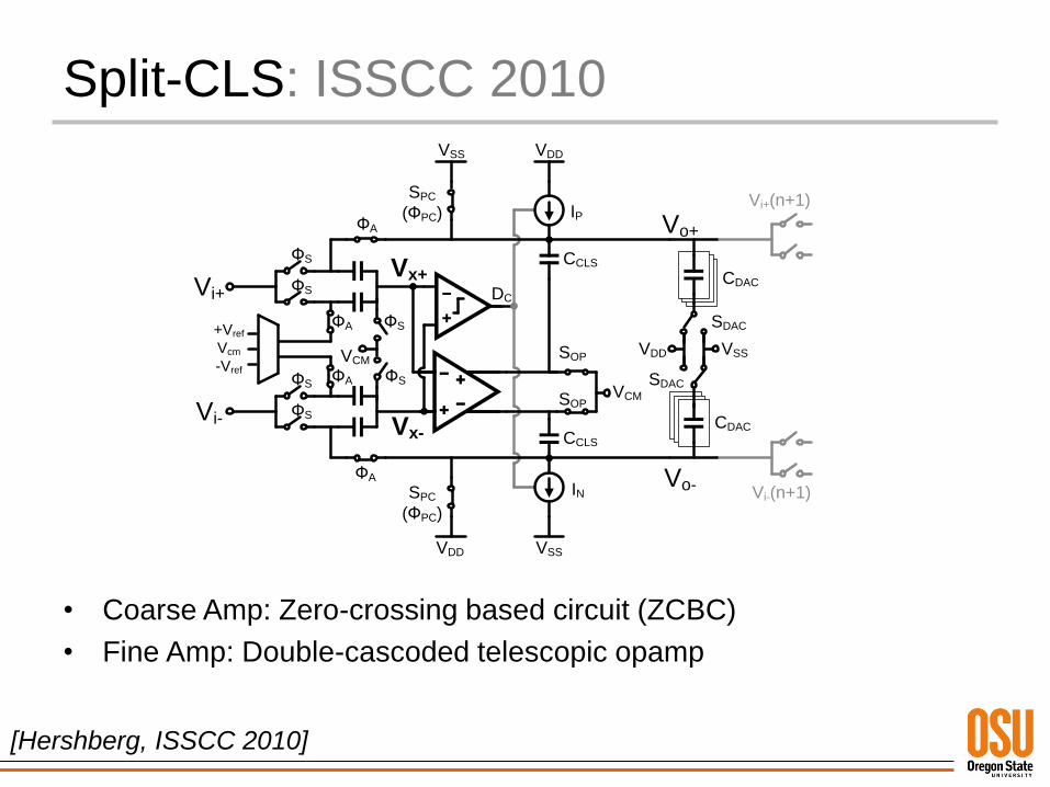
Split-CLS: ISSCC 2010
CCLS
CCLS
Vo+
Vo-
SPC
(ФPC)
VSS
VDDVSS
VDD
VSSVDD
VCM
VCM
+Vref
Vcm
-VrefФS
ФS
ФS
ФS
ФS
ФS
ФA
ФA
SOP
SOP
CDAC
CDACVi+
Vi-
ФA
ФA
Vi+(n+1)
Vi-(n+1)
DC
SDAC
SDAC
SPC
(ФPC)
IN
IP
Vx+
Vx-
• Coarse Amp: Zero-crossing based circuit (ZCBC)
• Fine Amp: Double-cascoded telescopic opamp
[Hershberg, ISSCC 2010]
±VREF
VIN+ VO+
ΦSE
ΦS
ΦA
RAMP
VCMX
CU
CLR
±VREF
VIN+ΦS
CU
VCMO
VOTA_CM
2CU
CLR
±VREF
VIN- VO-
ΦSE
ΦS
ΦA
RAMP
CU
CLR
±VREF
VIN-ΦS x6
(8 total)
CU
VCMO
2CU
CLR
CCLS
ΦSE
ΦSE
ΦCLS
ΦA
ΦA
OTA
x6
(8 total)
CCLS
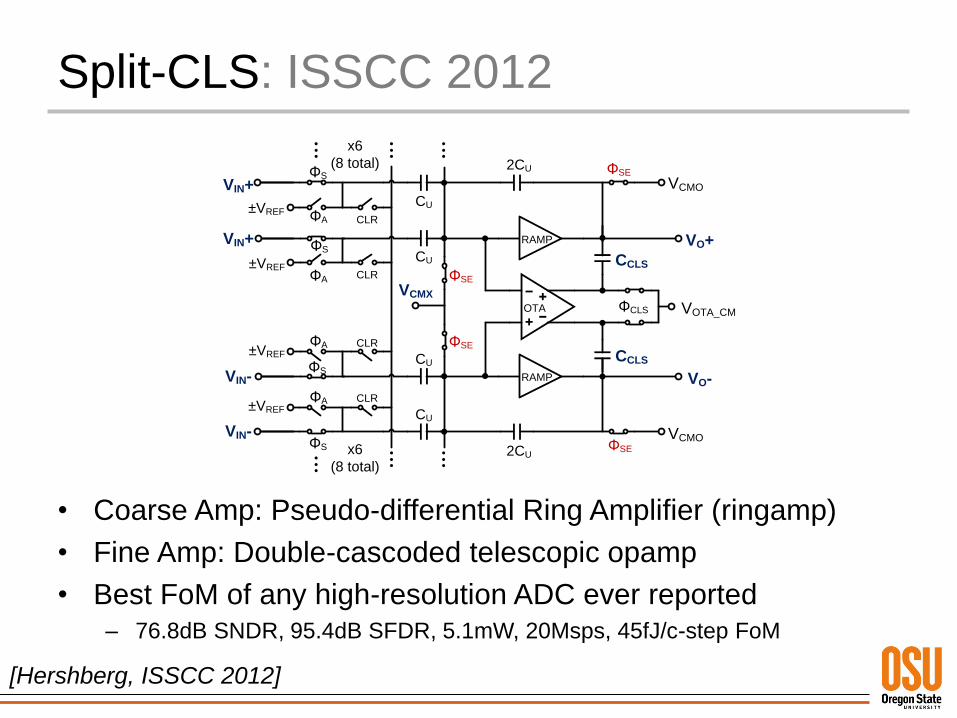
Split-CLS: ISSCC 2012
• Coarse Amp: Pseudo-differential Ring Amplifier (ringamp)
• Fine Amp: Double-cascoded telescopic opamp
• Best FoM of any high-resolution ADC ever reported– 76.8dB SNDR, 95.4dB SFDR, 5.1mW, 20Msps, 45fJ/c-step FoM
[Hershberg, ISSCC 2012]
Noise Analysis
Noise Analysis: Split-CLS
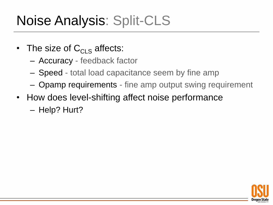
• The size of CCLS affects:
– Accuracy - feedback factor
– Speed - total load capacitance seem by fine amp
– Opamp requirements - fine amp output swing requirement
• How does level-shifting affect noise performance
– Help? Hurt?
Noise Analysis: Split-CLS
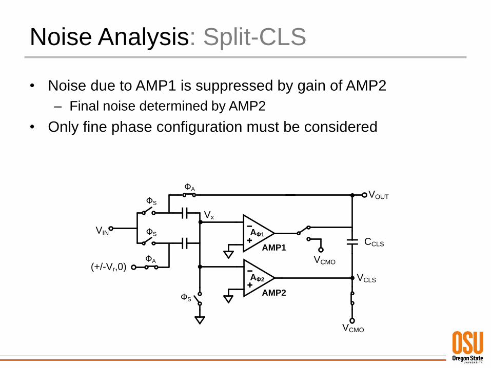
• Noise due to AMP1 is suppressed by gain of AMP2
– Final noise determined by AMP2
• Only fine phase configuration must be considered
CCLS
VOUTФS
ФA
VIN
ФA
VCMO
ФS
(+/-Vr,0)
AΦ1
AΦ2
Vx
VCLS
AMP1
AMP2
VCMO
ФS
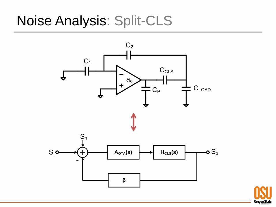
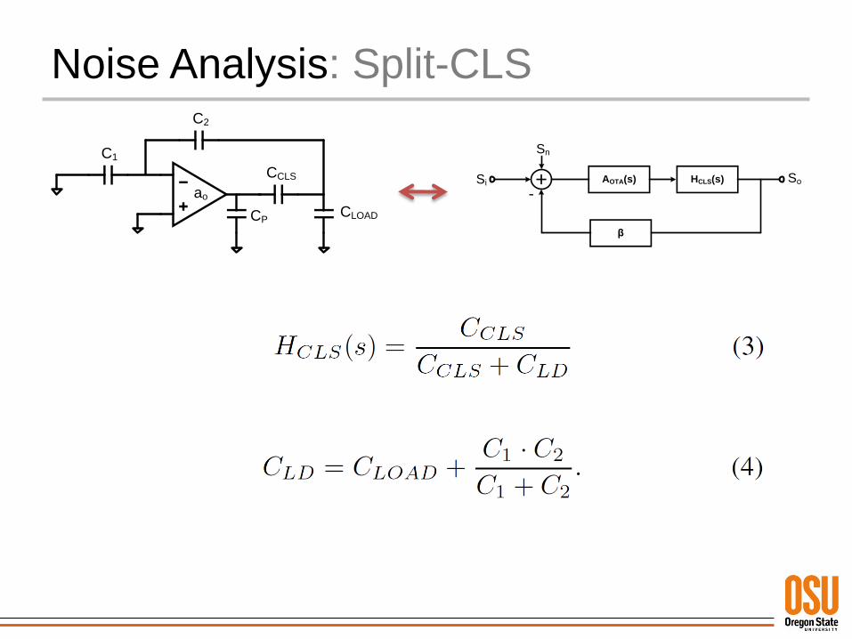
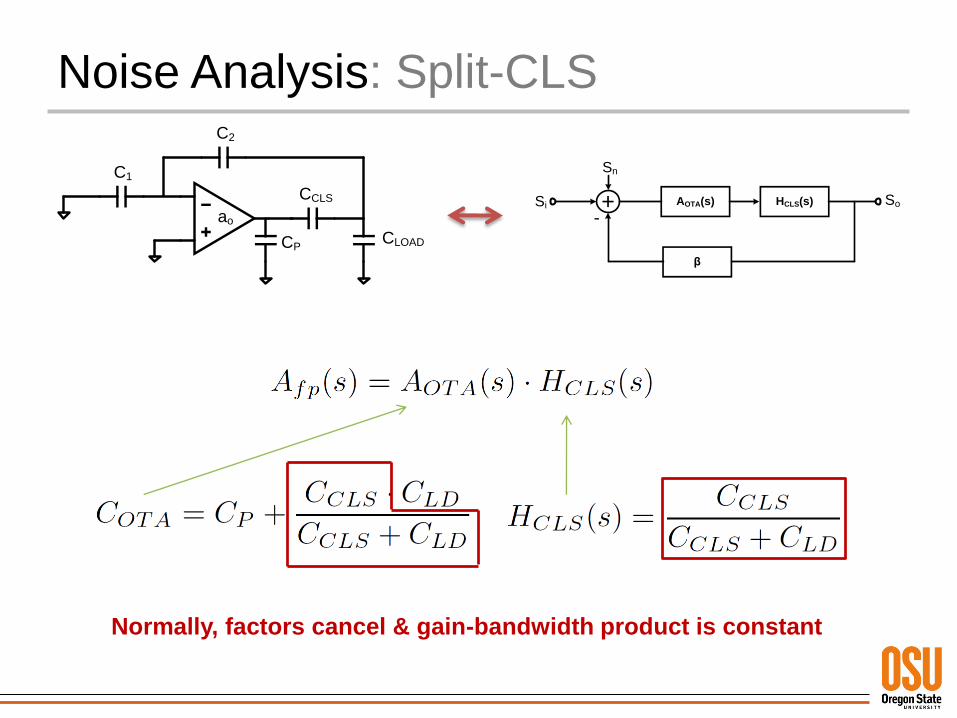
Noise Analysis: Split-CLS
C1
C2
CCLS
CLOADCP
ao
β
AOTA(s) HCLS(s) So
Sn
Si
-
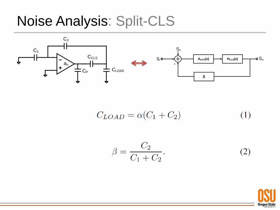
Noise Analysis: Split-CLS
C1
C2
CCLS
CLOADCP
ao
β
AOTA(s) HCLS(s) So
Sn
Si
-
Noise Analysis: Split-CLS
C1
C2
CCLS
CLOADCP
ao
β
AOTA(s) HCLS(s) So
Sn
Si
-
Noise Analysis: Split-CLS
C1
C2
CCLS
CLOADCP
ao
β
AOTA(s) HCLS(s) So
Sn
Si
-
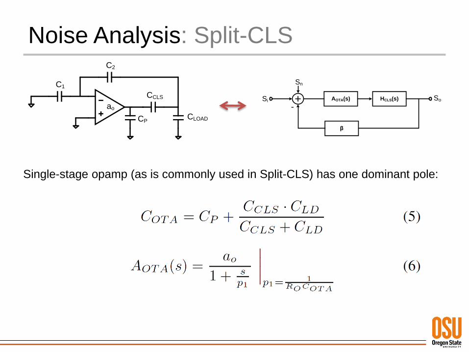
Single-stage opamp (as is commonly used in Split-CLS) has one dominant pole:
Noise Analysis: Split-CLS
C1
C2
CCLS
CLOADCP
ao
β
AOTA(s) HCLS(s) So
Sn
Si
-
Noise Analysis: Split-CLS
104
106
108
1010
1012
-80
-60
-40
-20
0
20
40
60
dB
Frequency (Hz)
Forward Path Gain
400fF
200fF
100fF
50fF
25fF
12.5fF
CCLS
=12.5fF
CCLS
=400fF
CCLS
β
AOTA(s) HCLS(s) So
Sn
Si
-
Gain-Bandwidth
Spreading
Noise Analysis: Split-CLS
C1
C2
CCLS
CLOADCP
ao
β
AOTA(s) HCLS(s) So
Sn
Si
-
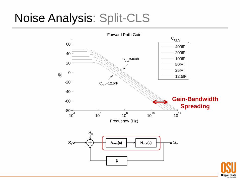
Normally, factors cancel & gain-bandwidth product is constant
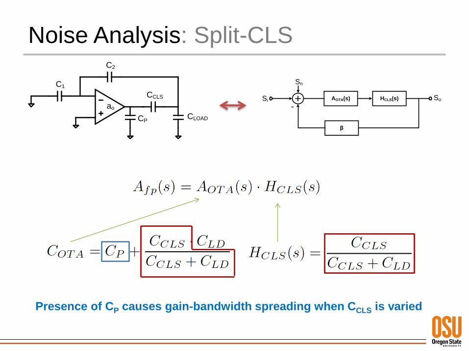
Noise Analysis: Split-CLS
C1
C2
CCLS
CLOADCP
ao
β
AOTA(s) HCLS(s) So
Sn
Si
-
Presence of CP causes gain-bandwidth spreading when CCLS is varied
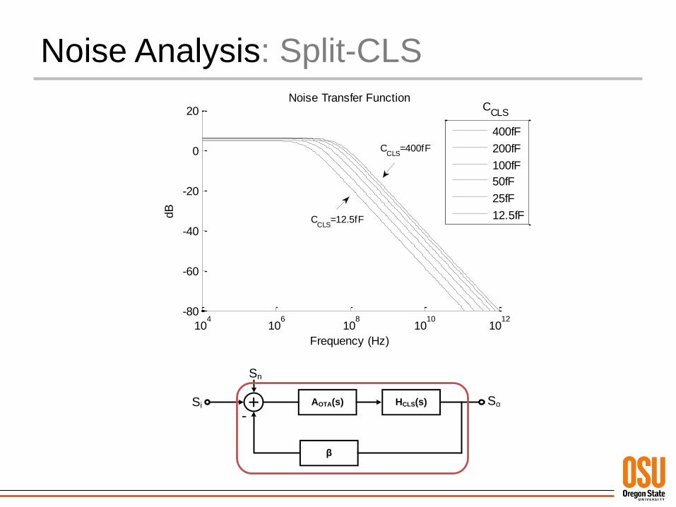
Noise Analysis: Split-CLS
104
106
108
1010
1012
-80
-60
-40
-20
0
20
dB
Frequency (Hz)
Noise Transfer Function
400fF
200fF
100fF
50fF
25fF
12.5fFCCLS
=12.5fF
CCLS
=400fF
CCLS
β
AOTA(s) HCLS(s) So
Sn
Si
-
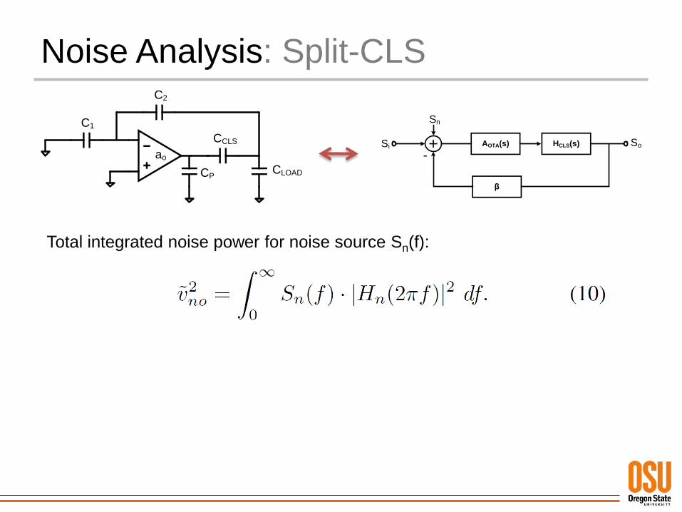
Noise Analysis: Split-CLS
C1
C2
CCLS
CLOADCP
ao
β
AOTA(s) HCLS(s) So
Sn
Si
-
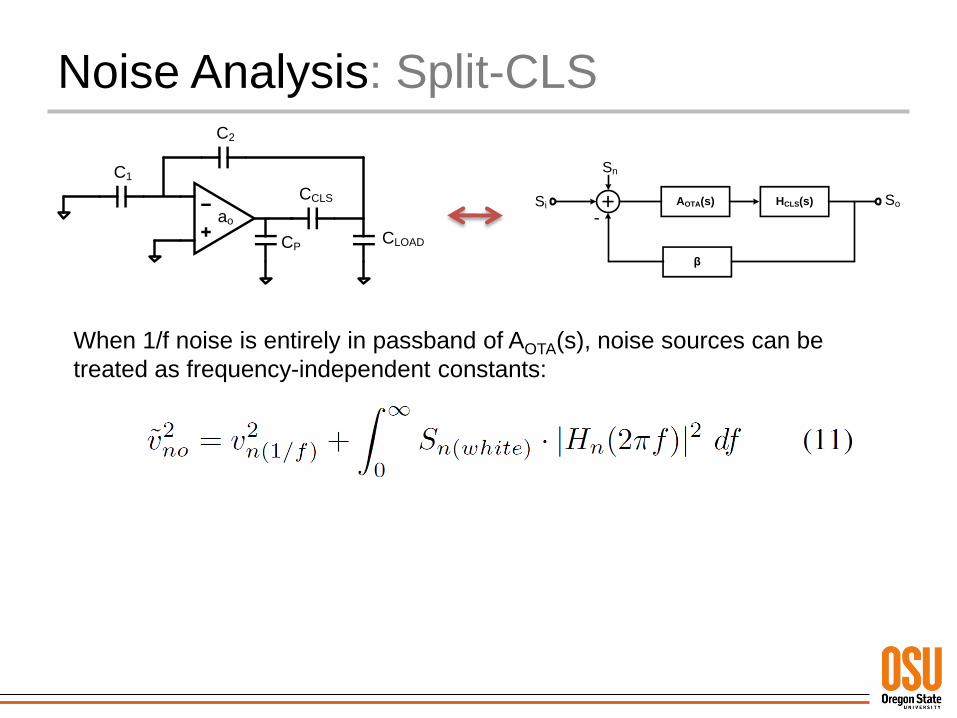
Total integrated noise power for noise source Sn(f):
Noise Analysis: Split-CLS
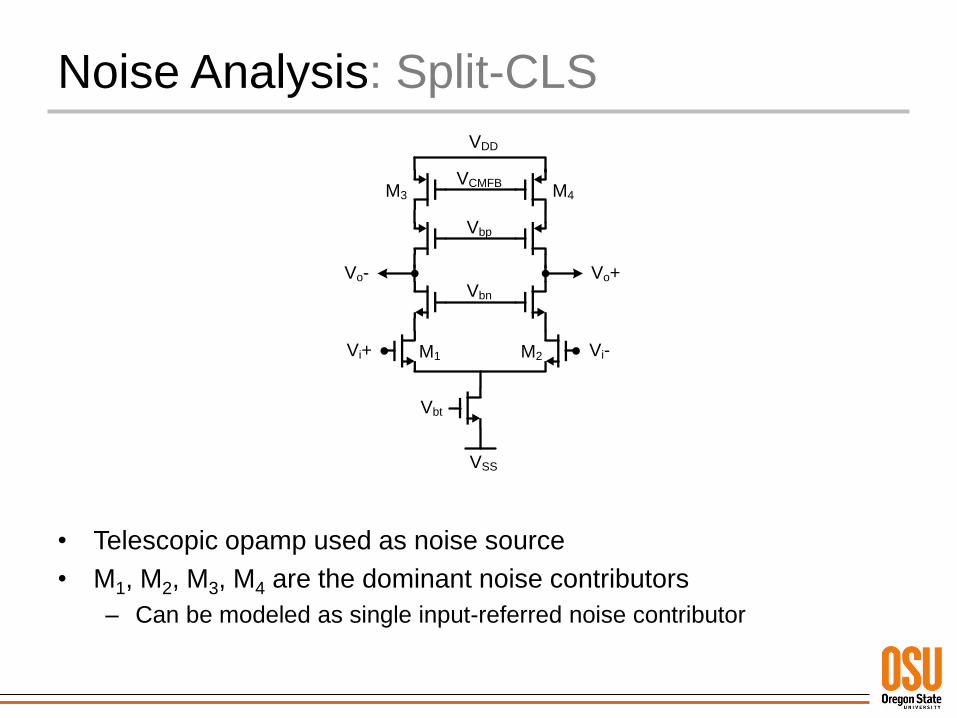
• Telescopic opamp used as noise source
• M1, M2, M3, M4 are the dominant noise contributors
– Can be modeled as single input-referred noise contributor
Vbn
Vbp
Vbt
Vi+ Vi-
Vo+Vo-
VCMFB
VDD
VSS
M1 M2
M3 M4
Noise Analysis: Split-CLS
C1
C2
CCLS
CLOADCP
ao
β
AOTA(s) HCLS(s) So
Sn
Si
-
When 1/f noise is entirely in passband of AOTA(s), noise sources can be
treated as frequency-independent constants:
Noise Analysis: Split-CLS
104
106
108
1010
1012
-240
-220
-200
-180
-160
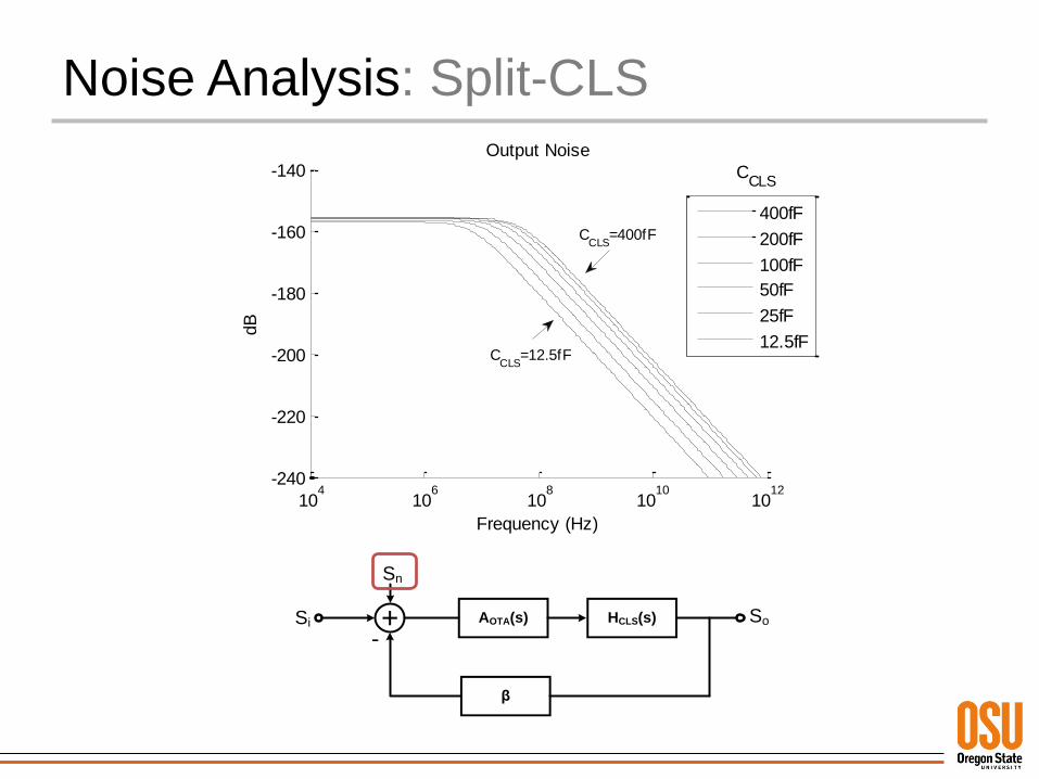
-140Output Noise
dB
Frequency (Hz)
400fF
200fF
100fF
50fF
25fF
12.5fFC
CLS=12.5fF
CCLS
=400fF
CCLS
β
AOTA(s) HCLS(s) So
Sn
Si
-
Noise Analysis: Split-CLS
0 200 400 600 800 10000
0.5
1
1.5
2
2.5
3
3.5x 10
-8
CCLS
( fF )
Inte
gra
ted N
ois
e P
ow
er
( V
2 )
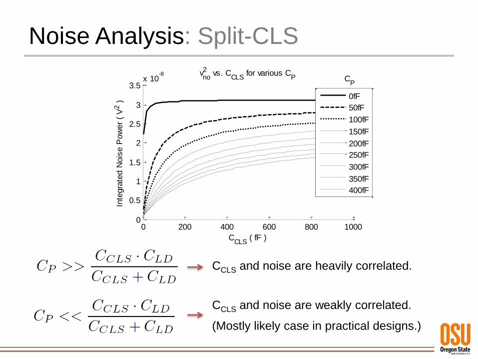
vno2 vs. C
CLS for various C
P
0fF
50fF
100fF
150fF
200fF
250fF
300fF
350fF
400fF
CP
CCLS and noise are heavily correlated.
CCLS and noise are weakly correlated.
(Mostly likely case in practical designs.)
Comparison with Simulation
Comparison with Simulation
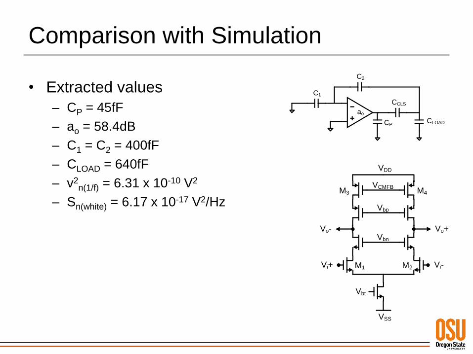
• Extracted values
– CP = 45fF
– ao = 58.4dB
– C1 = C2 = 400fF
– CLOAD = 640fF
– v2n(1/f) = 6.31 x 10⁻¹⁰ V2
– Sn(white) = 6.17 x 10⁻¹⁷ V2/Hz
C1
C2
CCLS
CLOADCP
ao
Vbn
Vbp
Vbt
Vi+ Vi-
Vo+Vo-
VCMFB
VDD
VSS
M1 M2
M3 M4
Comparison with Simulation
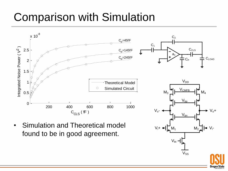
• Simulation and Theoretical model
found to be in good agreement.
200 400 600 800 10000
0.5
1
1.5
2
2.5
x 10-8
CCLS
( fF )
Inte
gra
ted N
ois
e P
ow
er
( V
2 )
Theoretical Model
Simulated Circuit
CP=245fF
CP=145fF
CP=45fF
C1
C2
CCLS
CLOADCP
ao
Vbn
Vbp
Vbt
Vi+ Vi-
Vo+Vo-
VCMFB
VDD
VSS
M1 M2
M3 M4

Comparison with Simulation
• Simulation and Theoretical model
found to be in good agreement.
102
103
0
0.5
1
1.5
2
2.5
x 10-8
CCLS
( fF )
Inte
gra
ted N
ois
e P
ow
er
( V
2 )
Theoretical Model
Cadence Simulation
CP=45fF
CP=145fF
CP=245fF
C1
C2
CCLS
CLOADCP
ao
Vbn
Vbp
Vbt
Vi+ Vi-
Vo+Vo-
VCMFB
VDD
VSS
M1 M2
M3 M4
Conclusion
Conclusion
• CLS and Split-CLS reduce finite-opamp gain error by approximately 1/A2
• Addition of CCLS network to MDAC structure introduces bandwidth spreading dependent on CCLS ↔ CP relation.
• For most practical Split-CLS designs, CCLS >> CP
– CCLS should be large enough to minimize swing requirement, maintain sufficient loop gain.
– CP is only intrinsic parasitic capacitances of opamp
• In practical cases, total integrated opamp noise is not significantly affected by Split-CLS.

Thank You For Your Attention