AC Measurements Using the Oscilloscope and Multimeter by Mr. David Fritz
© 2014 PMK GmbH
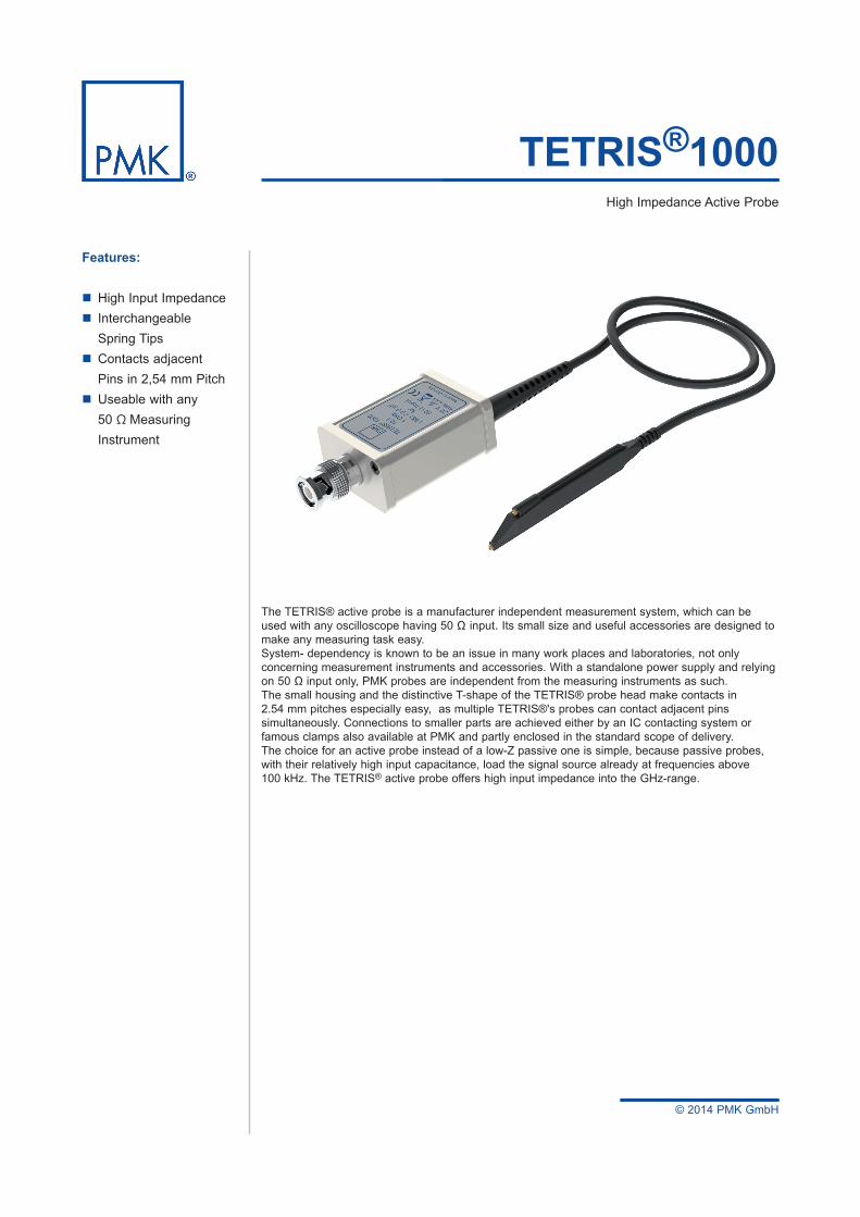
TETRIS®1000 High Impedance Active Probe
The TETRIS® active probe is a manufacturer independent measurement system, which can be used with any oscilloscope having 50 Ω input. Its small size and useful accessories are designed to make any measuring task easy. System- dependency is known to be an issue in many work places and laboratories, not only concerning measurement instruments and accessories. With a standalone power supply and relying on 50 Ω input only, PMK probes are independent from the measuring instruments as such.The small housing and the distinctive T-shape of the TETRIS® probe head make contacts in 2.54 mm pitches especially easy, as multiple TETRIS®'s probes can contact adjacent pins simultaneously. Connections to smaller parts are achieved either by an IC contacting system or famous clamps also available at PMK and partly enclosed in the standard scope of delivery.The choice for an active probe instead of a low-Z passive one is simple, because passive probes, with their relatively high input capacitance, load the signal source already at frequencies above 100 kHz. The TETRIS® active probe offers high input impedance into the GHz-range.
Features:
High Input Impedance Interchangeable Spring Tips Contacts adjacent Pins in 2,54 mm Pitch Useable with any 50 Ω Measuring Instrument
© 2014 PMK GmbH
2
TETRIS®1000
Datasheet
This datasheet supersedes all previously published material. Specifications that are not marked as quaranteed are published as general information to the user. The instrument should have warmed up for at least 20 minutes and the environmental conditions must not exceed the specified limits of the probe. Note that specifications are subject to change without notice.
Electrical Specifications Attenuation Ratio 10:1 ± 2 % at DCVoltage Coefficient 0.00025 % / V at DCInput Voltage (max) 20 VProbe Bandwidth 1.0 GHz (-3 dB)System Bandwidth (1) 600 MHz (-3 dB)Input Dynamic Range ±8 V
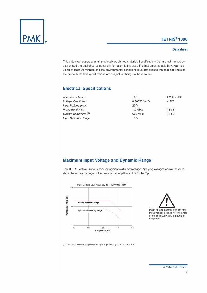
Maximum Input Voltage and Dynamic Range
The TETRIS Active Probe is secured against static overvoltage. Applying voltages above the ones stated here may damage or the destroy the amplifier at the Probe Tip.
(1) Connected to oscilloscope with an Input Impedance greater than 500 MHz
1G 10G100M10M1M1
10
100
Volta
ge [V
] AC
pea
k
Frequency [Hz]
Input Voltage vs. Frequency TETRIS® 1000 / 1500
Maximum Input Voltage
Dynamic Measuring Range Make sure to comply with the max. Input Voltages stated here to avoid errors of linearity and damage to the probe.
Input Voltage vs. Frequency TETRIS® 1000 / 1500
Frequency [Hz]
Volta
ge [V
] AC
pea
k
© 2014 PMK GmbH
3
TETRIS®1000
Datasheet
Electrical Characteristics
Input Resistance (system) 1 MΩ (± 1 %)Input Capacitance (system) 0.9 pF Input Coupling of the Measuring Instrument 50 ΩAC / DC
Mechanical Characteristics
Weight (probe only) 48 gCable Length 1.3 m
1k
1
10k
100k
1M
1k1 10 100 10k 100k 10M 100M1M 1G
Typical Input Impedance TETRIS® 1000 |Z
| [O
hm]
Frequency [Hz]
R1
R2
C1
C2
Ersatzschaltbild Tastkopf
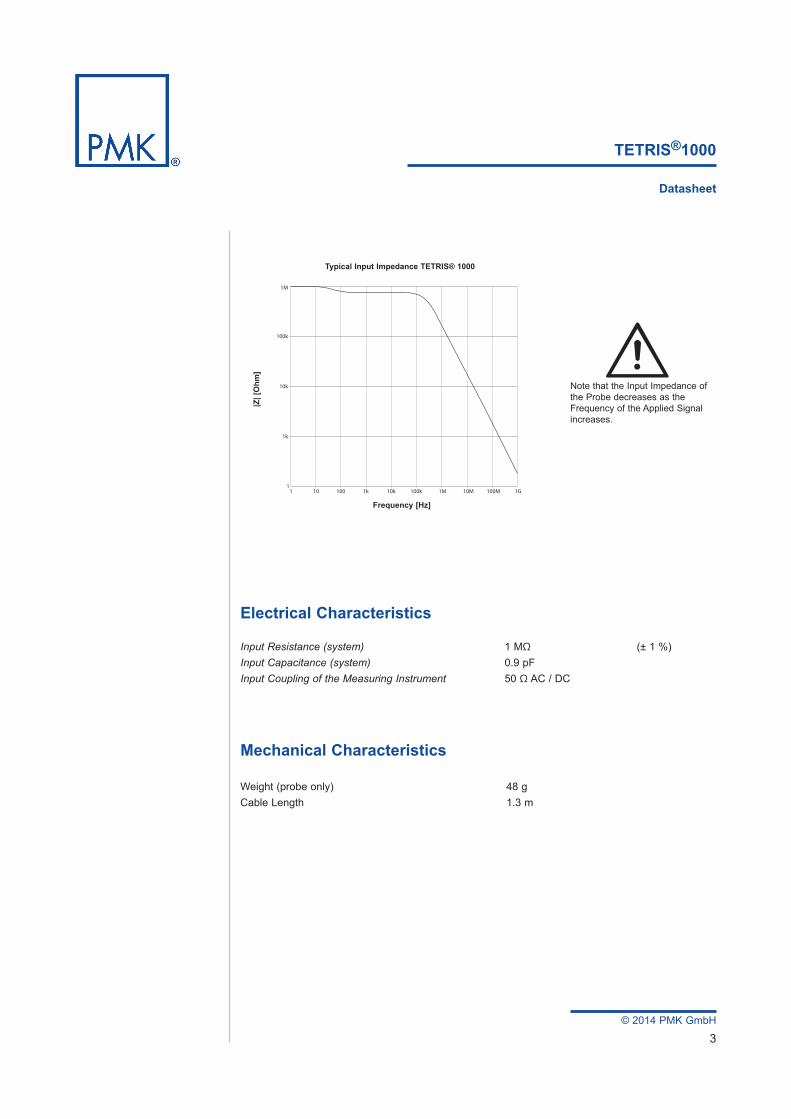
C1= 1,0 nF R1= 3 MΩC2= 0,88 pF R2= 1 MΩNote that the Input Impedance of
the Probe decreases as the Frequency of the Applied Signal increases.
Typical Input Impedance TETRIS® 1000
Frequency [Hz]
|Z| [
Ohm
]
© 2014 PMK GmbH
4
Environmental Specifications
Altitude operating up to 2000 m non-operating up to 15000 mTemperature Range operating 0 °C to +50 °C non-operating -40 °C to +71 °CMaximum Relative Humidity operating 80% relative humidity for temperatures up to +31 °C, decreasing linearly to 40 % at +50 °C
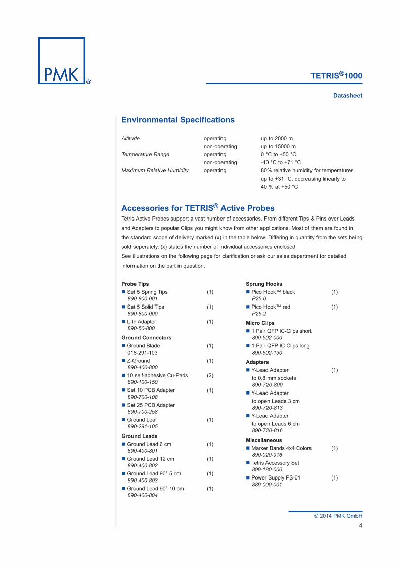
Accessories for TETRIS® Active ProbesTetris Active Probes support a vast number of accessories. From different Tips & Pins over Leads
and Adapters to popular Clips you might know from other applications. Most of them are found in
the standard scope of delivery marked (x) in the table below. Differing in quantity from the sets being
sold seperately, (x) states the number of individual accessories enclosed.
See illustrations on the following page for clarification or ask our sales department for detailed
information on the part in question.
TETRIS®1000
Datasheet
Probe Tips Set 5 Spring Tips (1) 890-800-001 Set 5 Solid Tips (1) 890-800-000 L-In Adapter (1) 890-50-800
Ground Connectors Ground Blade (1) 018-291-103 Z-Ground (1) 890-400-800 10 self-adhesive Cu-Pads (2) 890-100-150 Set 10 PCB Adapter (1) 890-700-108 Set 25 PCB Adapter 890-700-258 Ground Leaf (1) 890-291-105
Ground Leads Ground Lead 6 cm (1) 890-400-801 Ground Lead 12 cm (1) 890-400-802 Ground Lead 90° 5 cm (1) 890-400-803 Ground Lead 90° 10 cm (1) 890-400-804
Sprung Hooks Pico Hook™ black (1) P25-0 Pico Hook™ red (1) P25-2
Micro Clips 1 Pair QFP IC-Clips short 890-502-000 1 Pair QFP IC-Clips long 890-502-130
Adapters Y-Lead Adapter (1) to 0.8 mm sockets 890-720-800 Y-Lead Adapter to open Leads 3 cm 890-720-813 Y-Lead Adapter to open Leads 6 cm 890-720-816
Miscellaneous Marker Bands 4x4 Colors (1) 890-020-916 Tetris Accessory Set 899-180-000 Power Supply PS-01 (1) 889-000-001
© 2014 PMK GmbH
TETRIS®1000
Datasheet
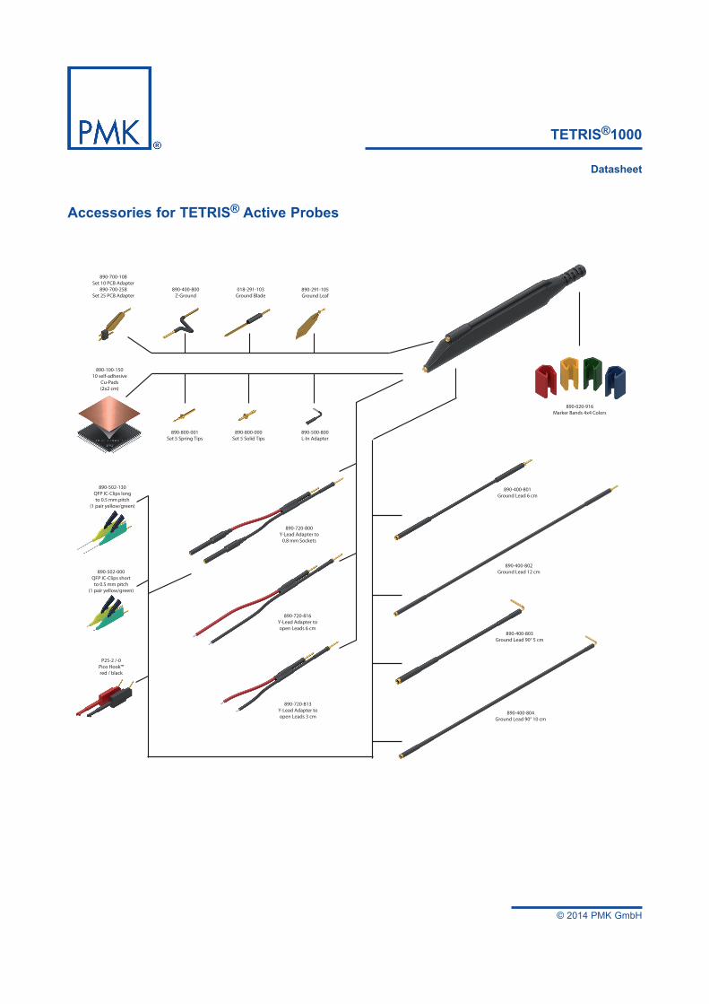
890-400-800Z-Ground
890-700-108Set 10 PCB Adapter
890-700-258Set 25 PCB Adapter
890-020-916Marker Bands 4x4 Colors
890-500-800L-In Adapter
890-720-816Y-Lead Adapter toopen Leads 6 cm
890-720-813Y-Lead Adapter toopen Leads 3 cm
890-720-800Y-Lead Adapter to
0.8 mm Sockets
P25-2 /-0Pico Hook™red / black
890-400-801Ground Lead 6 cm
890-400-802Ground Lead 12 cm
890-400-803Ground Lead 90° 5 cm
890-400-804Ground Lead 90° 10 cm
018-291-103Ground Blade
890-800-001Set 5 Spring Tips
890-800-000Set 5 Solid Tips
890-100-15010 self-adhesive
Cu-Pads(2x2 cm)
890-291-105Ground Leaf
890-502-130QFP IC-Clips longto 0.5 mm pitch
(1 pair yellow/green)
890-502-000QFP IC-Clips short
to 0.5 mm pitch(1 pair yellow/green)
Accessories for TETRIS® Active Probes
© 2014 PMK GmbH
6
TETRIS®1000
Datasheet
WEEE/ RoHS Directives
PMK electronic products are classified within the WEEE/ RoHS* category list as monitoring and control equipment (category 9). Category 9 products are exempt from the restrictions under the scope of the RoHS directive.
Your help and efforts are required to protect and keep clean our environment. Therefore return any electronic product at the end of its life either to Service Department of PMK Mess- und Kommunikationstechnik GmbH or take care of separate WEEE collection and professional WEEE treatment yourself. Do not dispose as unsorted municipal waste.
* EC Directives:WEEE Directive 2002/96/EC – Waste Electrical and Electronic EquipmentRoHS Directive 2002/95/EC – Restriction of the use of certain Hazardous Substances in Electrical and Electronic Equipment
Safety Information
To avoid personal injury and to prevent fire or damage to this product or products connected to it, review and comply with the safety informations stated in the manual before using this product. Be aware that if you use this probe assembly in a manner not specified the protection this product provides may be impaired.
Only qualified personnel should use this probe assembly.
Manufacturer
PMK Mess- und Kommunikationstechnik GmbHKönigsteiner Str. 9865812 Bad Soden, Germany Internet: www.pmk.de
Tel: +49 (0) 6196 5927 - 930 E-Mail: [email protected]
Fax: +49 (0) 6196 5927 - 939
Revision C - March 2014