TEST ON C1 P1 - atecorp.com · TEST ON 230V / 50Hz 600VA RS232C + ON OFF ... User's Manual...
25
C.A 6121 C2 P2 C1 P1 TEST MAINS TEST REMOTE WARNING LAMP 12V~ 1 - 1.25 - 1.5 kV~ START / STOP TEST ON 230V / 50Hz 600VA RS232C + ON OFF INSULATION (M ) Ω DISCHARGE TIME ( t) ∆ CONTINUITY 12V/>10A ( U,R ) ∆ 10A ~ DIELECTRIC (HV) 600V CAT III C.A 6121 MACHINE TESTER C.A 6121 MACHINE TESTER H V M Ω R 10 A ∆ t ∆ U ARNOUX CHAUVIN 500 - 1000 V MΩ 500V 150MΩ U=513V 9min 59s MΩ 113.5 Timer Rmin Un n CONTROLEUR "MACHINE" n MACHINE TESTER n MASCHINEN-TESTER n MACHINE TESTER n COMPROBADOR DE MAQUINARIA ELECTRICA Mode d'emploi User's Manual Bedienungsanleitung Libretto d'Istruzioni Manual de Instrucciones FRANCAIS ENGLISH DEUTSCH ITALIANO ESPAÑOL
Transcript of TEST ON C1 P1 - atecorp.com · TEST ON 230V / 50Hz 600VA RS232C + ON OFF ... User's Manual...
1
C.A 6121
C2P2C1 P1
TEST
MAINSTEST
REMOTE WARNING LAMP 12V~
1 - 1.25 - 1.5 kV~ START / STOP
TEST ON
230V / 50Hz600VA
RS232C
+ON
OFF
INSULATION (M )Ω DISCHARGE TIME ( t)∆
CONTINUITY 12V/>10A ( U,R )∆ 10A~
DIELECTRIC (HV)
600V CAT III
C.A 6121MACHINE TESTER
C.A 6121MACHINE TESTER
HVMΩR10A
∆t∆U
ARNOUXCHAUVIN
500 - 1000 V
MΩ 500V 150MΩ
U=513V
9min 59s
MΩ113.5
TimerRminUn
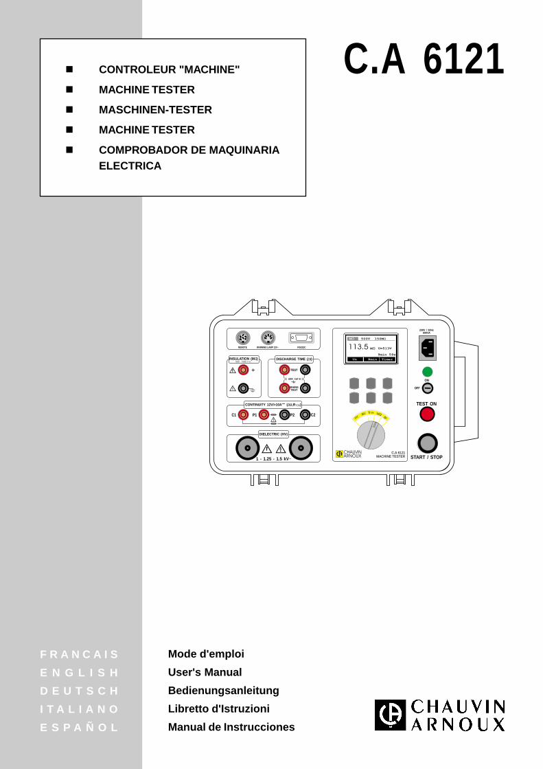
CONTROLEUR "MACHINE"
MACHINE TESTER
MASCHINEN-TESTER
MACHINE TESTER
COMPROBADOR DE MAQUINARIAELECTRICA
Mode d'emploi
User's Manual
Bedienungsanleitung
Libretto d'Istruzioni
Manual de Instrucciones
F R A N C A I S
E N G L I S H
D E U T S C H
I T A L I A N O
E S P A Ñ O L
26
The ! means Warning
For your safety, you must read carefully and respect the instructions of the present user’s manual.
You have just acquired a C.A 6121 Machine Tester and we thank you for your confidence.
! To get the best results with this instrument : read this user’s manual carefully, otherwise this instrument may be dangerous for the user, for the instrument itself or
for the circuit under test ! respect the safety precautions detailed in the present manual
! SAFETY PRECAUTIONS !
This instrument must be powered from a mains supply which has a protective earth terminal
The INSULATION, CONTINUITY or DIELECTRIC measurement terminals must only be connected to circuits that are not live.
If a fuse has blown in the instrument, please follow the instructions in this manual to replace it!
Any repair or metrological check procedure must be carried out by competent and approved personnel!
The C.A 6121 MACHINE TESTER must only be handled by a competent operator, familiar with equipment using dangerousvoltages !
Use connection accessories whose overvoltage category and service voltaage are greater than or equal to those of the circuitson which the measurements are made. Only use accessories that conform to safety standards (IEC 1010-2-032).
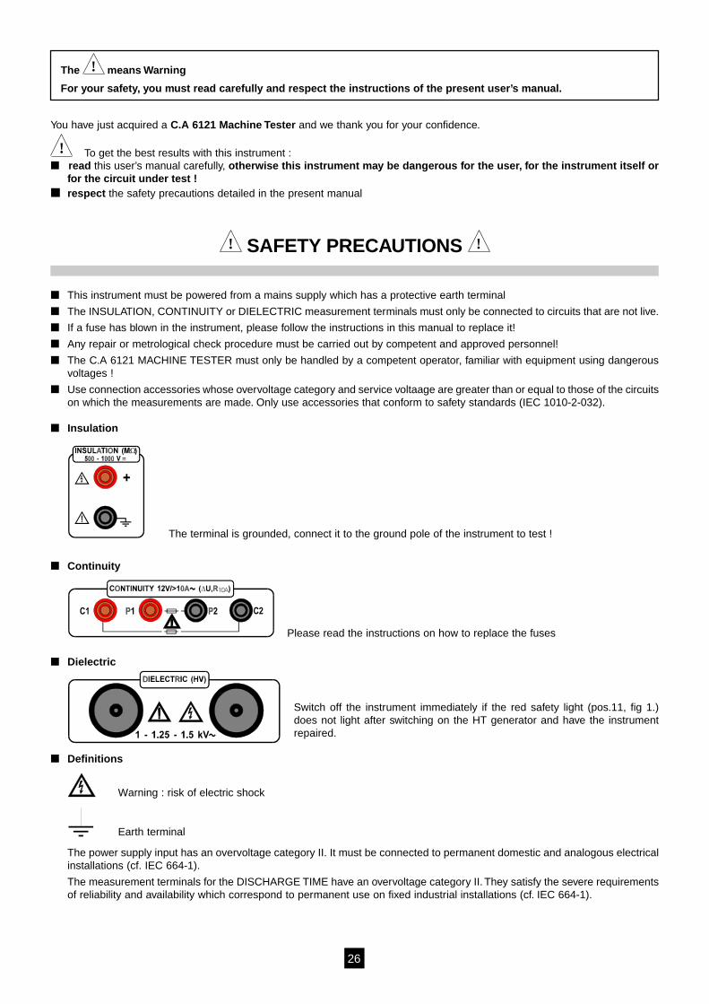
Insulation
The terminal is grounded, connect it to the ground pole of the instrument to test !
Continuity
Please read the instructions on how to replace the fuses
Dielectric
Switch off the instrument immediately if the red safety light (pos.11, fig 1.)does not light after switching on the HT generator and have the instrumentrepaired.
Definitions
Warning : risk of electric shock
Earth terminal
The power supply input has an overvoltage category II. It must be connected to permanent domestic and analogous electricalinstallations (cf. IEC 664-1).
The measurement terminals for the DISCHARGE TIME have an overvoltage category II. They satisfy the severe requirementsof reliability and availability which correspond to permanent use on fixed industrial installations (cf. IEC 664-1).
27
WARRANTY
Our guarantee is applicable for twelve months after the date on which the equipment is made available (extract from ourGeneral Conditions of Sale, available on request).
CONTENTS
1. GENERAL PRESENTATION ................................................................................................................................................. 28
2. DESCRIPTION OF THE INSTRUMENT ............................................................................................................................... 28
3. TECHNICAL SPECIFICATIONS ........................................................................................................................................... 293.1. Dielectric test (position HV) ....................................................................................................................................... 293.2. Voltage drop at 10 A AC (position ∆U) ...................................................................................................................... 303.3. Low resistance (position R 10 A) ................................................................................................................................. 303.4. Insulation resistance .................................................................................................................................................. 31
3.4.1 Rated voltage 500 V DC ................................................................................................................................. 313.4.2 Rated voltage 1000 V DC ............................................................................................................................... 31
3.5. Discharge time (position ∆t) ....................................................................................................................................... 313.5.1 Discharge time on mains supply socket (MAINS TEST inputs) ..................................................................... 313.5.2 Discharge time on internal electronic components (TEST inputs) ................................................................. 31
3.6. General specifications ............................................................................................................................................... 32
4. MEASUREMENTS ................................................................................................................................................................ 324.1. Dielectric test ............................................................................................................................................................. 324.2. Voltage drop scaled to 10 A (position ∆U) ................................................................................................................ 344.3. Low resistance (position R10A) .................................................................................................................................. 354.4. Insulation resistance .................................................................................................................................................. 364.5. Discharge time - 2 pole system ................................................................................................................................. 374.6. Discharge time - 4 pole system ................................................................................................................................. 38
5. OPERATION ......................................................................................................................................................................... 395.1. Warnings .................................................................................................................................................................... 395.2. Memorising the results .............................................................................................................................................. 405.3. Recalling stored results ............................................................................................................................................. 405.4. RS232 communication (for printout and connection to a PC) ................................................................................... 415.5 Erasing the results ..................................................................................................................................................... 435.6. Reinitialising the instrument ...................................................................................................................................... 445.7. Configuration ............................................................................................................................................................. 44
5.7.1. Display contrast .............................................................................................................................................. 445.7.2. Time and date ................................................................................................................................................ 455.7.3. Warning buzzer .............................................................................................................................................. 455.7.4. Baud rate ........................................................................................................................................................ 46
5.8. Sound signals ............................................................................................................................................................ 465.9 Use of remote control pedal ...................................................................................................................................... 465.10 Use of warning lamps (standard VDE 104) ............................................................................................................... 47
6. MAINTENANCE .................................................................................................................................................................... 486.1. Usual cleaning ........................................................................................................................................................... 486.2. Replacing the fuses (for properly qualified maintenance personnel only !) .............................................................. 486.3 Metrological check ..................................................................................................................................................... 486.4. After sales service ..................................................................................................................................................... 48
7. TO ORDER ........................................................................................................................................................................... 49
27
28
1. GENERAL PRESENTATION
This machine has been designed for testing the electrical safety of machines, in conformity with standard EN60204-1, parts 19 -1 to19-5.
Its worksite case is hardwearing, but also easy to carry to your measurement site. Its interface, simple to use, gives you very rapidaccess to all the main functions of the instrument. Its optional accessories allow it to be adapted to all specific environments.
List of measurements that the instrument can perform :
Dielectric test with a test voltage of 1000 V AC Dielectric test with a test voltage of 1250 V AC Dielectric test with a test voltage of 1500 V AC Voltage drop scaled to 10 A AC with a test voltage of 12 V / > 10 A AC Low resistance with a test voltage of 12 V / >10 A AC Insulation resistance with a test voltage of 500 V DC Insulation resistance with a test voltage of 1000 V DC Two pole discharge time (residual voltage) Four pole discharge time (residual voltage)
2. DESCRIPTION OF THE INSTRUMENT
C2P2C1 P1
TEST
MAINSTEST
REMOTE WARNING LAMP 12V~
1 - 1.25 - 1.5 kV~ START/STOP
TEST ON
230V / 50Hz600VA
RS232C
+ON
OFF
INSULATION (M )Ω500 - 1000 V
DISCHARGE TIME ( t)∆
CONTINUITY 12V/>10A ( U,R )∆ 10A~
DIELECTRIC (HV)
600V CAT III
C.A 6121MACHINE TESTER
C.A 6121MACHINE TESTER
MΩ 500V 150MΩ
U=513V
9min 59s
MΩ113.5
TimerRminUn
HVMΩR10A
∆t∆U
ARNOUXCHAUVIN
MEM/MR PRINT/RS / SET-UPMEM/MR PRINT/RS SET-UP
1 2 3 4 5 6 7 8
9
10
11
12
1314151617
18
19
20
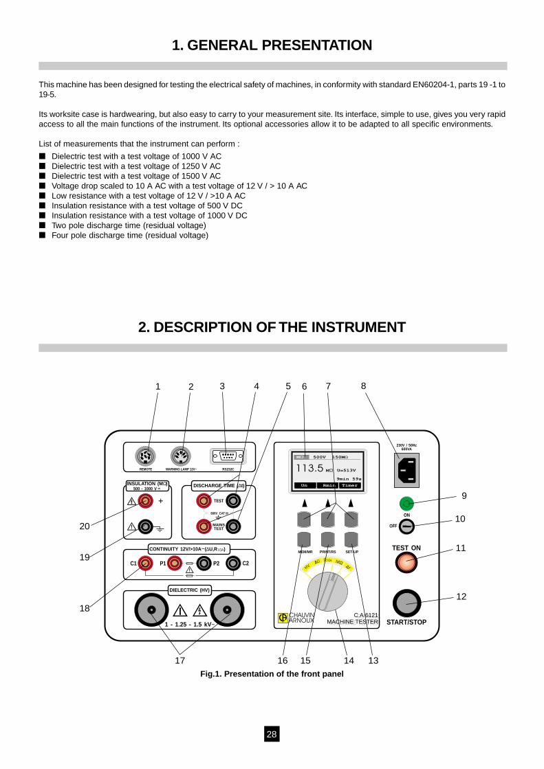
Fig.1. Presentation of the front panel
29
1 REMOTE connector to connect a REMOTE CONTROL PEDAL2 WARNING LAMP connector to connect external WARNING LAMPS (standard VDE 104)3 RS 232 connector to connect external printer or PC4 DISCHARGE TIME - TEST terminals to be used in four pole measurement5 DISCHARGE TIME - MAINS TEST terminals to be used in 2 or 4 pole measurement6 LCD dot matrix display with continuous back light7 GENERAL KEYS (see the function of each key on the LCD)8 MAINS CONNECTOR (mains power supply of the instrument)9 POWER ON indicator light10 POWER ON / OFF key11 TEST ON warning light12 START/STOP push button13 SET UP key to set:
- contrast of the display- real time clock and date- buzzer (on/off)- baud rate
14 ROTARY SWITCH to select the functions15 PRINT/RS key to:
- transmit memorised data to a PC- print memorized data to external printer
16 MEM/MR key to:- memorize results- recall memorized results- erade memorized results
17 DIELECTRIC test terminals18 CONTINUITY test terminals (current terminals C1, C2 and potential test terminals P1, P2)19 Grounded INSULATION test terminal20 Positive INSULATION test terminal
3. TECHNICAL SPECIFICATIONS
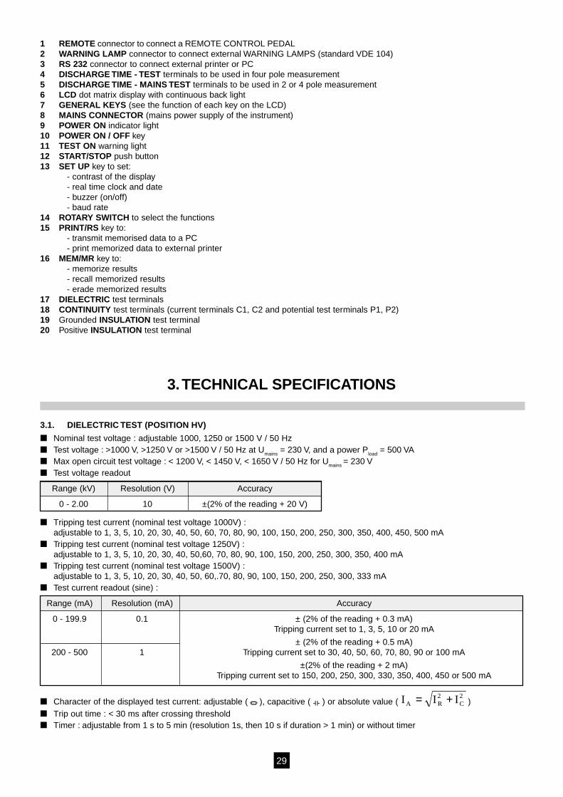
3.1. DIELECTRIC TEST (POSITION HV)
Nominal test voltage : adjustable 1000, 1250 or 1500 V / 50 Hz Test voltage : >1000 V, >1250 V or >1500 V / 50 Hz at Umains = 230 V, and a power Pload = 500 VA Max open circuit test voltage : < 1200 V, < 1450 V, < 1650 V / 50 Hz for Umains = 230 V Test voltage readout
Range (kV) Resolution (V) Accuracy
0 - 2.00 10 ±(2% of the reading + 20 V)
Tripping test current (nominal test voltage 1000V) :adjustable to 1, 3, 5, 10, 20, 30, 40, 50, 60, 70, 80, 90, 100, 150, 200, 250, 300, 350, 400, 450, 500 mA
Tripping test current (nominal test voltage 1250V) :adjustable to 1, 3, 5, 10, 20, 30, 40, 50,60, 70, 80, 90, 100, 150, 200, 250, 300, 350, 400 mA
Tripping test current (nominal test voltage 1500V) :adjustable to 1, 3, 5, 10, 20, 30, 40, 50, 60,.70, 80, 90, 100, 150, 200, 250, 300, 333 mA
Test current readout (sine) :
Range (mA) Resolution (mA) Accuracy
0 - 199.9 0.1 ± (2% of the reading + 0.3 mA)Tripping current set to 1, 3, 5, 10 or 20 mA
± (2% of the reading + 0.5 mA)200 - 500 1 Tripping current set to 30, 40, 50, 60, 70, 80, 90 or 100 mA
±(2% of the reading + 2 mA)Tripping current set to 150, 200, 250, 300, 330, 350, 400, 450 or 500 mA
Character of the displayed test current: adjustable ( ), capacitive ( ) or absolute value ( I I IA R C= +2 2)
Trip out time : < 30 ms after crossing threshold Timer : adjustable from 1 s to 5 min (resolution 1s, then 10 s if duration > 1 min) or without timer

30
3.2.VOLTAGE DROP SCALED TO 10 A AC (POSITION ∆∆∆∆∆U)
Voltage drop readout :
Range ∆U (V) Resolution (V) Accuracy
0 - 10 0.01 ±(2% of the reading + 0.02 V)
Test voltage readout :
Range (V) Resolution (V) Accuracy
0 - 12 0.01 ±(2% of the reading + 0.02 V)
Test current readout :
Range (A) Resolution (A) Accuracy
0 - 9.99 0.01 ±(5% of the reading + 2 pt.)
10.0 - 25.0 0.1 ±3% of the reading
Max permitted voltage drop depending on the cross section of the cable :
Cross section of the cable (mm2) Max voltage drop (V)
0.5 5
0.75 5
1 3.3
1.5 2.6
2.5 1.9
4 1.4
≥ 6 1.0
Max output voltage : 12 V AC Measurement current (0 - 0.5 Ω) : > 10 A AC Timer : adjustable from 1 to 15 s (resolution 1s) or without timer Connection system : 4 wire
3.3. LOW RESISTANCE (POSITION R10A)
Resistance readout :
Range R * Resolution (mΩ) Accuracy
0-999 mΩ 1 ±(2% of the reading + 2 mΩ)
1.00 - 1.99 Ω 10 ± 5% of the reading
* automatic ranges
Max output voltage : 12 V AC Measurement current (0 - 0.5 Ω) : > 10 A AC Threshold value : adjustable from 10 mΩ to 1000 mΩ (resolution 10 mΩ ) then from 1000 mΩ to 2000 mΩ
(resolution of 100 mΩ) or without threshhold (* mΩ) Timer : adjustable from 1 to 15 s (resolution 1 s) or without timer Connection system : 4 wire Test voltage readout :
Range (V) Resolution (V) Accuracy
0 - 12 0.01 ±(2% of the reading + 0.02 V)
Test current readout :
Range (A) Resolution (A) Accuracy
0 - 9.99 0.01 ±(5% of the reading + 2 pt.)
10.0 - 25.0 0.1 ±(2% of the reading)
31
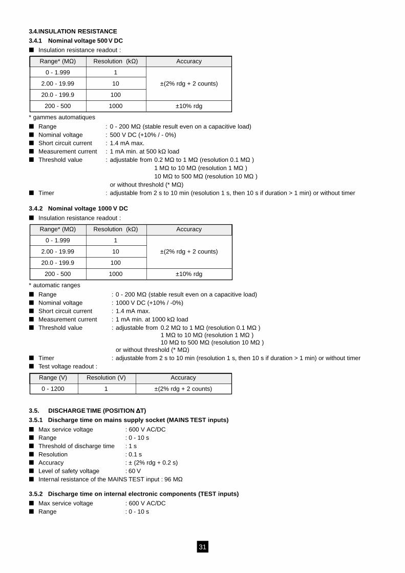
3.4.INSULATION RESISTANCE
3.4.1 Nominal voltage 500 V DC
Insulation resistance readout :
Range* (MΩ) Resolution (kΩ) Accuracy
0 - 1.999 1
2.00 - 19.99 10 ±(2% rdg + 2 counts)
20.0 - 199.9 100
200 - 500 1000 ±10% rdg
* gammes automatiques
Range : 0 - 200 MΩ (stable result even on a capacitive load) Nominal voltage : 500 V DC (+10% / - 0%) Short circuit current : 1.4 mA max. Measurement current : 1 mA min. at 500 kΩ load Threshold value : adjustable from 0.2 MΩ to 1 MΩ (resolution 0.1 MΩ )
1 MΩ to 10 MΩ (resolution 1 MΩ )10 MΩ to 500 MΩ (resolution 10 MΩ )
or without threshold (* MΩ) Timer : adjustable from 2 s to 10 min (resolution 1 s, then 10 s if duration > 1 min) or without timer
3.4.2 Nominal voltage 1000 V DC
Insulation resistance readout :
Range* (MΩ) Resolution (kΩ) Accuracy
0 - 1.999 1
2.00 - 19.99 10 ±(2% rdg + 2 counts)
20.0 - 199.9 100
200 - 500 1000 ±10% rdg
* automatic ranges
Range : 0 - 200 MΩ (stable result even on a capacitive load) Nominal voltage : 1000 V DC (+10% / -0%) Short circuit current : 1.4 mA max. Measurement current : 1 mA min. at 1000 kΩ load Threshold value : adjustable from 0.2 MΩ to 1 MΩ (resolution 0.1 MΩ )
1 MΩ to 10 MΩ (resolution 1 MΩ )10 MΩ to 500 MΩ (resolution 10 MΩ )
or without threshold (* MΩ) Timer : adjustable from 2 s to 10 min (resolution 1 s, then 10 s if duration > 1 min) or without timer Test voltage readout :
Range (V) Resolution (V) Accuracy
0 - 1200 1 ±(2% rdg + 2 counts)
3.5. DISCHARGE TIME (POSITION ∆∆∆∆∆T)
3.5.1 Discharge time on mains supply socket (MAINS TEST inputs)
Max service voltage : 600 V AC/DC Range : 0 - 10 s Threshold of discharge time : 1 s Resolution : 0.1 s Accuracy : ± (2% rdg + 0.2 s) Level of safety voltage : 60 V Internal resistance of the MAINS TEST input : 96 MΩ
3.5.2 Discharge time on internal electronic components (TEST inputs)
Max service voltage : 600 V AC/DC Range : 0 - 10 s
32
Threshold of discharge time : 5 s Resolution : 0.1 s Accuracy : ± (2% of the reading +0.2 s) Level of safety voltage : 60 V Internal resistance of the TEST input : 96 MΩ
3.6. GENERAL SPECIFICATIONS
Mains voltage : 230 V / 50 Hz Max power absorbed : 600 VA Screen : LCD dot matrix,128 x 64 counts with continuous backlight Interface RS232 : 1 start bit, 8 data bits, 1 stop bit, XON/XOFF protocol,
Baud rate adjustable to 300, 600, 1200, 2400, or 4800 Bauds Memories : 999 memory locations Remote control signals : START/STOP, SAVE Protection of the measurement circuits : F1 F 20 A/600 V 10.3 x 38 mm (Continuity/ ammeter)
F2 T 1 A/250 V 5 x 20 mm (warning lamp output)F3 T 4 A/250 V 5 x 20 mm (general protection of the instrument)F4 F 0.2 A/250 V 6.3 x 32 mm (Continuity/ voltmeter)
Shockproof plastic case Dimensions : (W x H x L) 400 x 260 x 250 mm Weight : 11 kg Protection index : IP 40 (open) IP54 (closed) Working temperature range : 0...+50°C Reference temperature range : +5...+35°C Storage temperature range : -10...+60°C Max working humidity : 85% RH (0...+40°C) Max storage humidity : 90% RH (-10...+40°C)
80% RH (+40...+60°C) Use indoors Altitude < 2000 m Dielectric strength test
- between mains and dielectric terminals: 4300 Vrms / 1 min- between mains and other terminals or accessible metallic parts: 3700 Vrms / 1 min
List of standards respected by the tester :Protection class 1 (with protection earth terminal)IEC 1010-1 : Pollution degree 2EN 60204-1 : Test of electric machinesVDE 104 : Installation and operation of electric test equipmentEN 61180-1.2 : High tension test techniques for low voltage equipmentEN 50081-1 : EMCEN 50082-2 : EMC
4. MEASUREMENTS
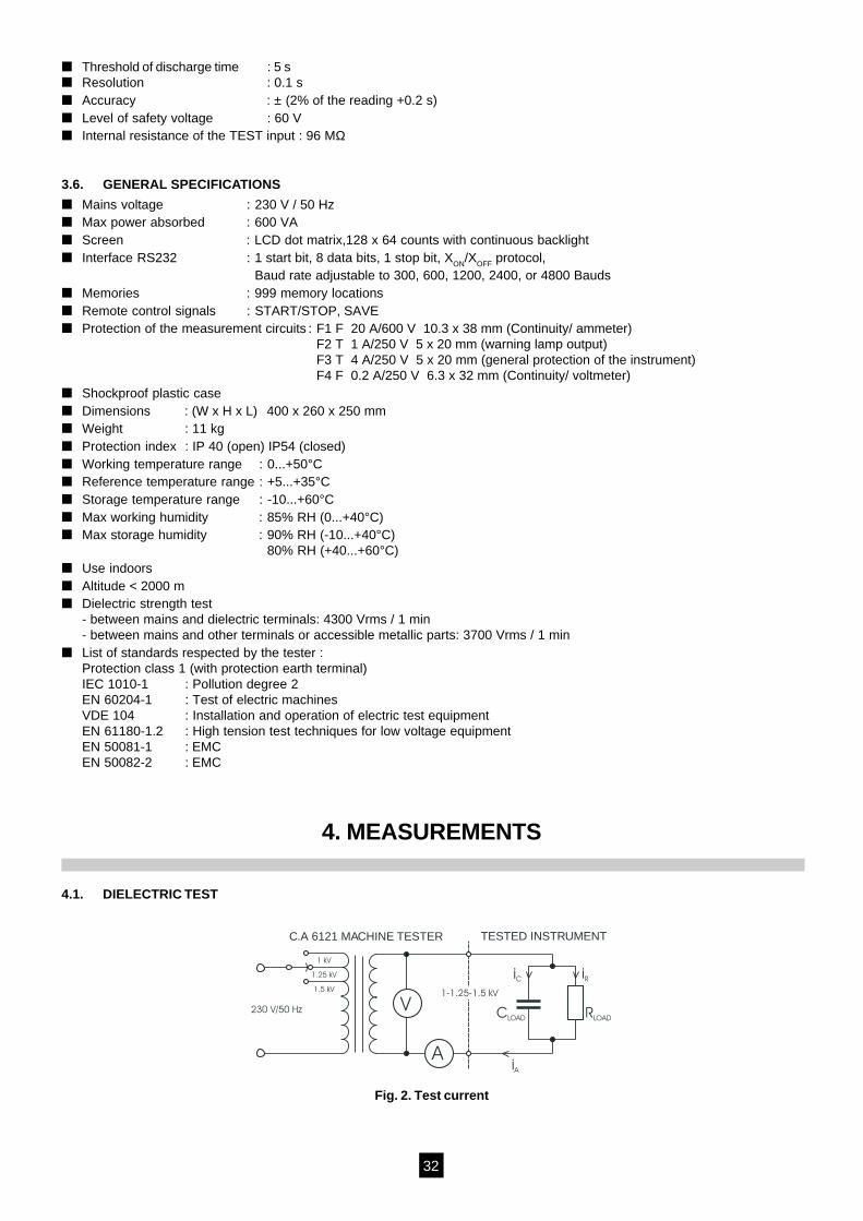
4.1. DIELECTRIC TEST
Fig. 2. Test current
RLOADCLOAD
iC iR
iA
230 V/50 Hz
1 kV
1.25 kV
1.5 kV
V
A
C.A 6121 MACHINE TESTER TESTED INSTRUMENT
1-1.25-1.5 kV
33
iR0
iC
-jIm
Re
iA i .....absolute value of currentA
i = i + iA C R
i .....capacitive currentC
i .....resistive currentR
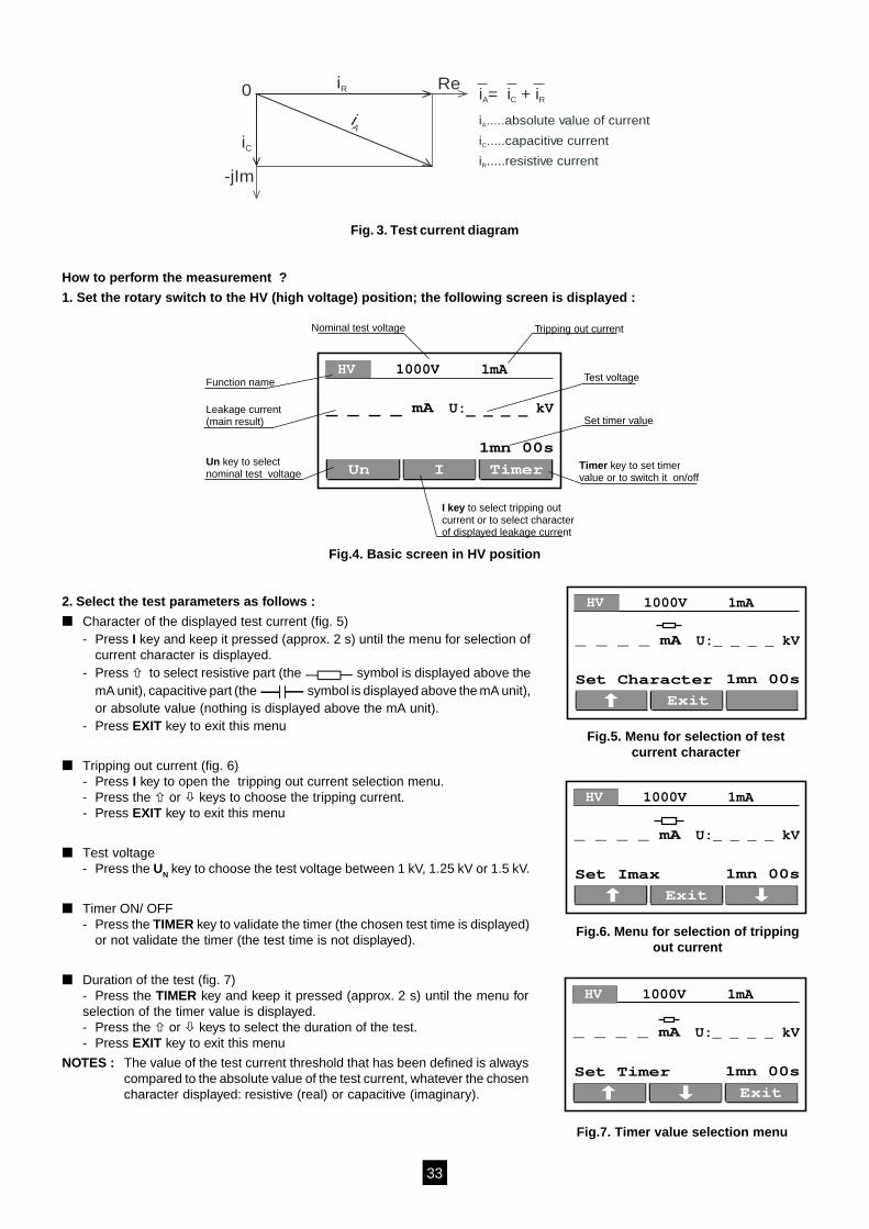
Fig. 3. Test current diagram
How to perform the measurement ?
1. Set the rotary switch to the HV (high voltage) position; the following screen is displayed :
1mn 00s
_ _ _ _ mA
TimerIUn
U:_ _ _ _ kV
HV 1000V 1mAFunction name
Nominal test voltage Tripping out current
Test voltage
Set timer value
Timer key to set timervalue or to switch it on/off
I key to select tripping outcurrent or to select characterof displayed leakage current
Leakage current(main result)
Un key to selectnominal test voltage
Fig.4. Basic screen in HV position
2. Select the test parameters as follows :
Character of the displayed test current (fig. 5)- Press I key and keep it pressed (approx. 2 s) until the menu for selection of
current character is displayed.- Press to select resistive part (the symbol is displayed above the
mA unit), capacitive part (the symbol is displayed above the mA unit),or absolute value (nothing is displayed above the mA unit).
- Press EXIT key to exit this menu
Tripping out current (fig. 6)- Press I key to open the tripping out current selection menu.- Press the or keys to choose the tripping current.- Press EXIT key to exit this menu
Test voltage- Press the UN key to choose the test voltage between 1 kV, 1.25 kV or 1.5 kV.
Timer ON/ OFF- Press the TIMER key to validate the timer (the chosen test time is displayed)
or not validate the timer (the test time is not displayed).
Duration of the test (fig. 7)- Press the TIMER key and keep it pressed (approx. 2 s) until the menu forselection of the timer value is displayed.- Press the or keys to select the duration of the test.- Press EXIT key to exit this menu
NOTES : The value of the test current threshold that has been defined is alwayscompared to the absolute value of the test current, whatever the chosencharacter displayed: resistive (real) or capacitive (imaginary).
1mn 00s
_ _ _ _ mA
Exit
Set Character
U:_ _ _ _ kV
HV 1000V 1mA
Fig.5. Menu for selection of testcurrent character
1mn 00s
_ _ _ _ mA
Exit
Set Imax
U:_ _ _ _ kV
HV 1000V 1mA
Fig.6. Menu for selection of trippingout current
1mn 00s
_ _ _ _ mA
Exit
Set Timer
U:_ _ _ _ kV
HV 1000V 1mA
Fig.7. Timer value selection menu
34
RLOADR=100i Ω ∆U
C2
iTEST
P2
P1
C1
230V/50Hz V
A
C.A 6121 MACHINE TESTER OBJECT UNDER TESTF1
F4
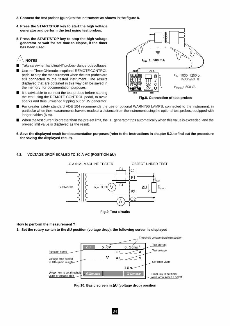
3. Connect the test probes (guns) to the instrument as shown in the figure 8.
4. Press the START/STOP key to start the high voltagegenerator and perform the test using test probes.
5. Press the START/STOP key to stop the high voltagegenerator or wait for set time to elapse, if the timerhas been used.
! NOTES : Take care when handling HT probes - dangerous voltages!
Use the Timer ON mode or optional REMOTE CONTROLpedal to stop the measurement when the test probes arestill connected to the tested instrument. The resultsdisplayed that are obtained in this way can be saved inthe memory for documentation purposes.
It is advisable to connect the test probes before startingthe test using the REMOTE CONTROL pedal, to avoidsparks and thus unwished tripping out of HV generator.
For greater safety standard VDE 104 recommends the use of optional WARNING LAMPS, connected to the instrument, inparticular when the measurements have to made at a distance from the instrument using the optional test probes, equipped withlonger cables (6 m).
When the test current is greater than the pre-set limit, the HT generator trips automatically when this value is exceeded, and thepre-set limit value is displayed as the result.
6. Save the displayed result for documentation purposes (refer to the instructions in chapter 5.2. to find out the procedurefor saving the displayed result).
4.2. VOLTAGE DROP SCALED TO 10 A AC (POSITION ∆∆∆∆∆U)
U :n
P :transf.
I :lim
1000, 1250 or1500 V/50 Hz
500 VA
1...500 mA
C2P2C1 P1
600V 250V CAT III600V
TEST
MAINSTEST
REMOTE WARNING LAMP 12V~
1 - 1.25 - 1.5 kV START / STOP
TEST ON
230V / 50Hz500VA
RS232C
MEM/MR PRINT/RS SET-UP
C.A 6121MACHINE TESTER
+ON
OFF
HV
MΩR10A
∆t∆U
ARNOUXCHAUVIN
INSULATION (M )Ω500 - 1000 V
DISCHARGE TIME ( t)∆
CONTINUITY 12V/>10A ( U,R )∆ 10A
DIELECTRIC (HV)
Fig.8. Connection of test probes
Fig.9. Test circuits
How to perform the measurement ?
1. Set the rotary switch to the ∆∆∆∆∆U position (voltage drop); the following screen is displayed :
10s
_ _ _ _ V
Timer∆Umax
I:_ _ _ _ A
U:_ _ _ _ V
∆U 5.0V 0.50mm2
Function name
Threshold voltage drop/wire section
Test voltage
Test current
Set timer value
Timer key to set timervalue or to switch it on/off
Voltage drop scaledto 10A (main result)
Umax key to set thresholdvalue of voltage drop
Fig.10. Basic screen in ∆∆∆∆∆U (voltage drop) position
35
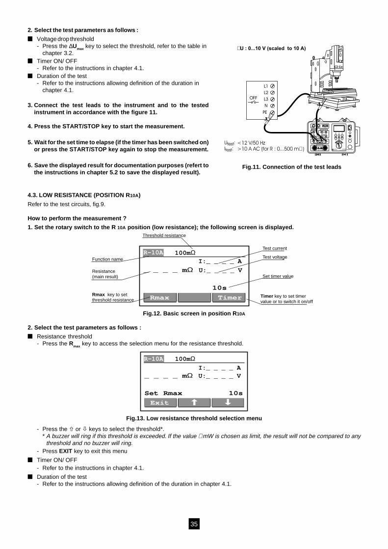
2. Select the test parameters as follows :
Voltage drop threshold- Press the ∆Umax key to select the threshold, refer to the table in
chapter 3.2. Timer ON/ OFF
- Refer to the instructions in chapter 4.1. Duration of the test
- Refer to the instructions allowing definition of the duration inchapter 4.1.
3. Connect the test leads to the instrument and to the testedinstrument in accordance with the figure 11.
4. Press the START/STOP key to start the measurement.
5. Wait for the set time to elapse (if the timer has been switched on)or press the START/STOP key again to stop the measurement.
6. Save the displayed result for documentation purposes (refert tothe instructions in chapter 5.2 to save the displayed result).
4.3. LOW RESISTANCE (POSITION R10A)
Refer to the test circuits, fig.9.
How to perform the measurement ?
1. Set the rotary switch to the R 10A position (low resistance); the following screen is displayed.
10s
_ _ _ _ mΩ
TimerRmax
U:_ _ _ _ V
I:_ _ _ _ A
R-10A 100mΩFunction name
Threshold resistance
Test voltage
Test current
Set timer value
Timer key to set timervalue or to switch it on/off
Resistance(main result)
Rmax key to setthreshold resistance
Fig.12. Basic screen in position R10A
2. Select the test parameters as follows :
Resistance threshold- Press the Rmax key to access the selection menu for the resistance threshold.
10sSet Rmax
_ _ _ _ mΩ
Exit
U:_ _ _ _ VI:_ _ _ _ A
R-10A 100mΩ
Fig.13. Low resistance threshold selection menu
- Press the or keys to select the threshold*.* A buzzer will ring if this threshold is exceeded. If the value ∗ mW is chosen as limit, the result will not be compared to any
threshold and no buzzer will ring.- Press EXIT key to exit this menu
Timer ON/ OFF- Refer to the instructions in chapter 4.1.
Duration of the test- Refer to the instructions allowing definition of the duration in chapter 4.1.
L1
L2
L3OFF
N
PE
U :I :
test
test
U : 0...10 V (scaled to 10 A)
<12 V/50 Hz>10 A AC (for R : 0...500 m )
C2P2C1 P1
600V 250V CAT III600V
TEST
MAINSTEST
REMOTE WARNING LAMP 12V~
1 - 1.25 - 1.5 kV START / STOP
TEST ON
230V / 50Hz500VA
RS232C
MEM/MR PRINT/RS SET-UP
C.A 6121MACHINE TESTER
+
ON
OFF
HVM
R10A
tU
ARNOUXCHAUVIN
INSULATION (M )500 - 1000 V
DISCHARGE TIME ( t)
CONTINUITY 12V/>10A ( U,R ) 10A
DIELECTRIC (HV)
Fig.11. Connection of the test leads
36
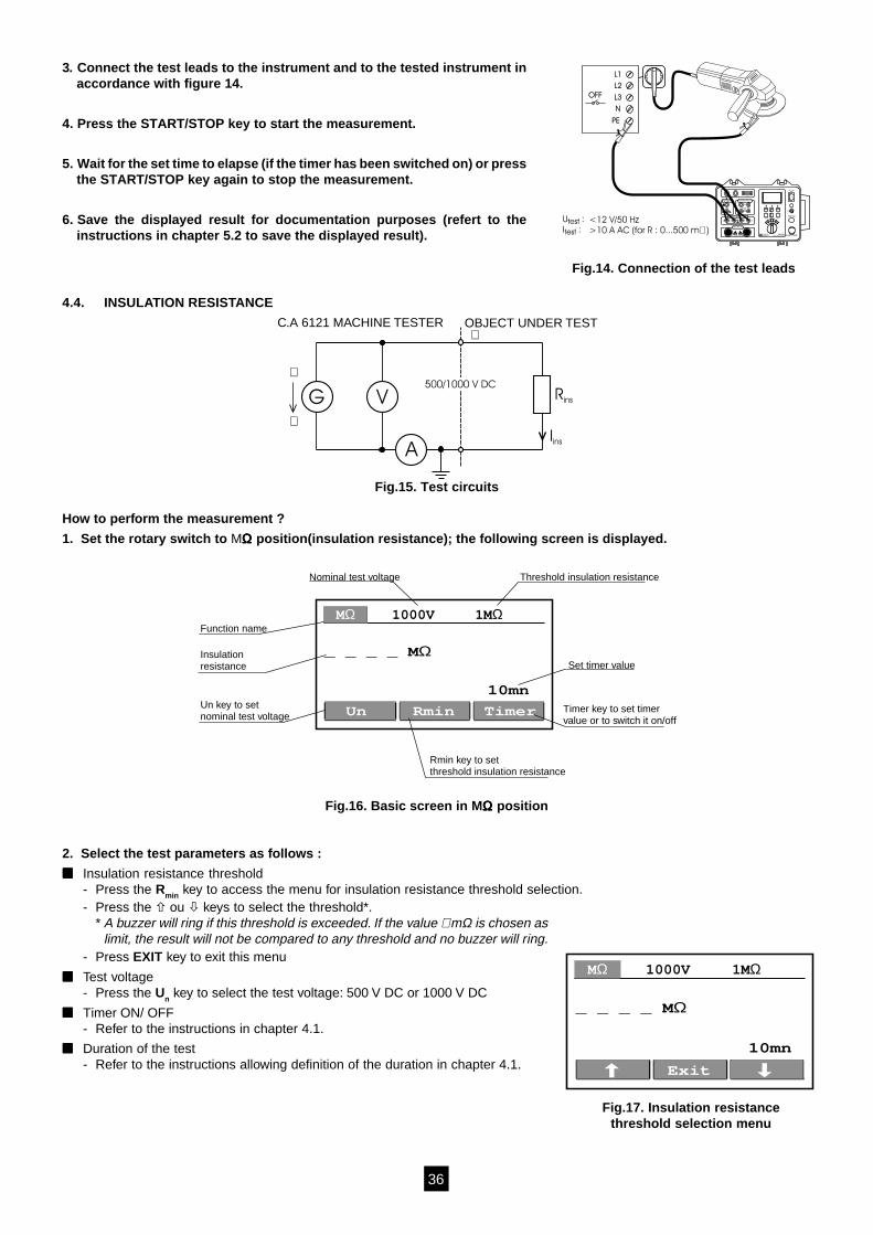
3. Connect the test leads to the instrument and to the tested instrument inaccordance with figure 14.
4. Press the START/STOP key to start the measurement.
5. Wait for the set time to elapse (if the timer has been switched on) or pressthe START/STOP key again to stop the measurement.
6. Save the displayed result for documentation purposes (refert to theinstructions in chapter 5.2 to save the displayed result).
4.4. INSULATION RESISTANCE
Rins
Iins
G V
A
C.A 6121 MACHINE TESTER OBJECT UNDER TEST
500/1000 V DC
Fig.15. Test circuits
How to perform the measurement ?
1. Set the rotary switch to MΩΩΩΩΩ position(insulation resistance); the following screen is displayed.
10mn
_ _ _ _ MΩ
TimerRminUn
1000V 1MΩMΩFunction name
Nominal test voltage Threshold insulation resistance
Set timer value
Timer key to set timervalue or to switch it on/off
Rmin key to setthreshold insulation resistance
Insulationresistance
Un key to setnominal test voltage
Fig.16. Basic screen in MΩΩΩΩΩ position
2. Select the test parameters as follows :
Insulation resistance threshold- Press the Rmin key to access the menu for insulation resistance threshold selection.- Press the ou keys to select the threshold*.
* A buzzer will ring if this threshold is exceeded. If the value ∗ mΩ is chosen aslimit, the result will not be compared to any threshold and no buzzer will ring.
- Press EXIT key to exit this menu
Test voltage- Press the Un key to select the test voltage: 500 V DC or 1000 V DC
Timer ON/ OFF- Refer to the instructions in chapter 4.1.
Duration of the test- Refer to the instructions allowing definition of the duration in chapter 4.1.
10mn
_ _ _ _ MΩ
Exit
1000V 1MΩMΩ
Fig.17. Insulation resistancethreshold selection menu
L1
L2
L3OFF
N
PE
U :I :
test
test
<12 V/50 Hz>10 A AC (for R : 0...500 m )
C2P2C1 P1
600V 250V CAT III600V
TEST
MAINSTEST
REMOTE WARNING LAMP 12V~
1 - 1.25 - 1.5 kV START / STOP
TEST ON
230V / 50Hz500VA
RS232C
MEM/MR PRINT/RS SET-UP
C.A 6121MACHINE TESTER
+
ON
OFF
HVM
R10A
tU
ARNOUXCHAUVIN
INSULATION (M )500 - 1000 V
DISCHARGE TIME ( t)
CONTINUITY 12V/>10A ( U,R ) 10A
DIELECTRIC (HV)
Fig.14. Connection of the test leads
37
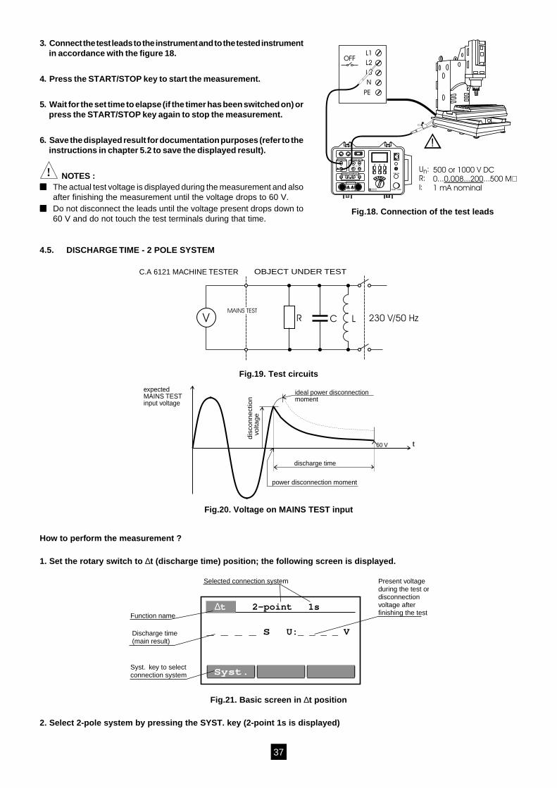
3. Connect the test leads to the instrument and to the tested instrumentin accordance with the figure 18.
4. Press the START/STOP key to start the measurement.
5. Wait for the set time to elapse (if the timer has been switched on) orpress the START/STOP key again to stop the measurement.
6. Save the displayed result for documentation purposes (refer to theinstructions in chapter 5.2 to save the displayed result).
! NOTES : The actual test voltage is displayed during the measurement and also
after finishing the measurement until the voltage drops to 60 V. Do not disconnect the leads until the voltage present drops down to
60 V and do not touch the test terminals during that time.
4.5. DISCHARGE TIME - 2 POLE SYSTEM
R 230 V/50 HzC LV
C.A 6121 MACHINE TESTER OBJECT UNDER TEST
MAINS TEST
Fig.19. Test circuits
discharge time
60 V t
expectedMAINS TESTinput voltage
dis
con
ne
ctio
nvo
ltag
e
ideal power disconnectionmoment
power disconnection moment
Fig.20. Voltage on MAINS TEST input
How to perform the measurement ?
1. Set the rotary switch to ∆t (discharge time) position; the following screen is displayed.
U:_ _ _ _ V_ _ _ _ S
Syst.
2-point 1s∆tFunction name
Selected connection system Present voltageduring the test ordisconnectionvoltage afterfinishing the test
Discharge time(main result)
Syst. key to selectconnection system
Fig.21. Basic screen in ∆t position
2. Select 2-pole system by pressing the SYST. key (2-point 1s is displayed)
L1
L2
L3
OFF
N
PE
U :R:I:
n 500 or 1000 V DC0... ...500 M1 mA nominal
0,008...200
600V 250V CAT III
1 - 1.25 - 1.5 kV START / STOP
TEST ON
+
HVM
R10A
tU
ARNOUXCHAUVIN
INSULATION (M )500 - 1000 V
DISCHARGE TIME ( t)
CONTINUITY 12V/>10A ( U,R ) 10A
DIELECTRIC (HV)
Fig.18. Connection of the test leads
38
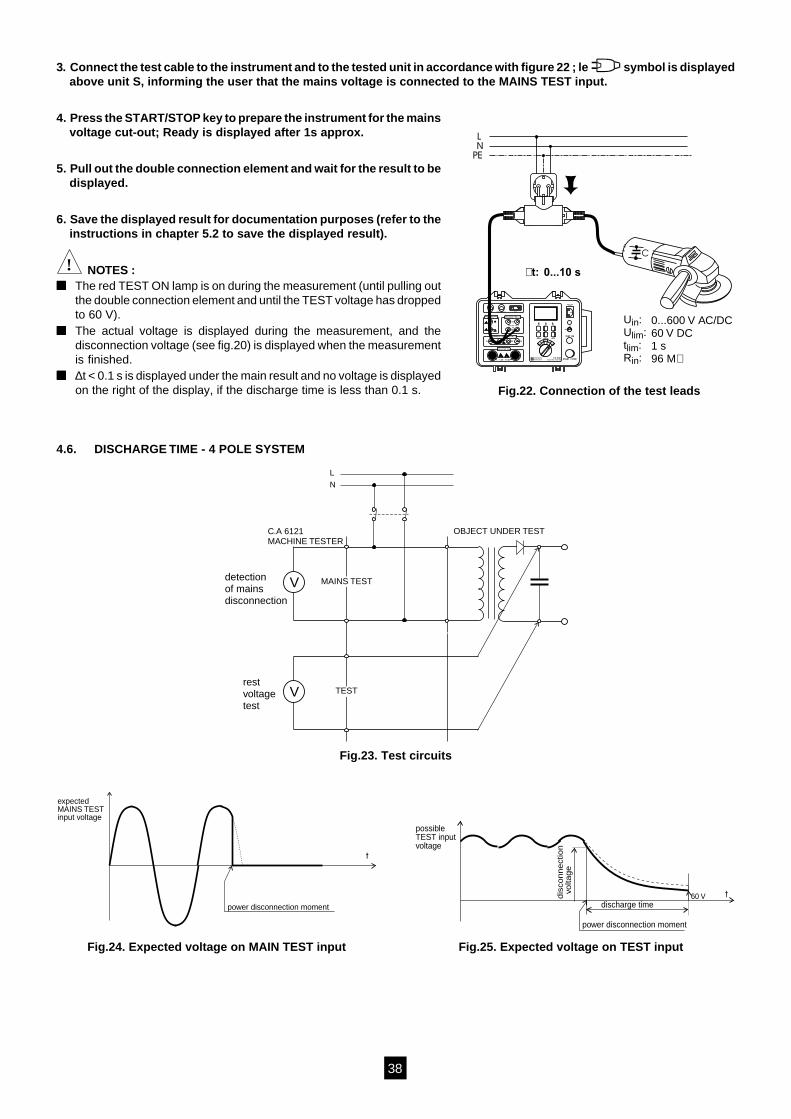
3. Connect the test cable to the instrument and to the tested unit in accordance with figure 22 ; le symbol is displayedabove unit S, informing the user that the mains voltage is connected to the MAINS TEST input.
4. Press the START/STOP key to prepare the instrument for the mainsvoltage cut-out; Ready is displayed after 1s approx.
5. Pull out the double connection element and wait for the result to bedisplayed.
6. Save the displayed result for documentation purposes (refer to theinstructions in chapter 5.2 to save the displayed result).
! NOTES : The red TEST ON lamp is on during the measurement (until pulling out
the double connection element and until the TEST voltage has droppedto 60 V).
The actual voltage is displayed during the measurement, and thedisconnection voltage (see fig.20) is displayed when the measurementis finished.
∆t < 0.1 s is displayed under the main result and no voltage is displayedon the right of the display, if the discharge time is less than 0.1 s.
4.6. DISCHARGE TIME - 4 POLE SYSTEM
L
N
V
V
C.A 6121MACHINE TESTER
detectionof mainsdisconnection
restvoltagetest
OBJECT UNDER TEST
MAINS TEST
TEST
Fig.23. Test circuits
t
expectedMAINS TESTinput voltage
power disconnection moment discharge time60 V t
possibleTEST inputvoltage
dis
con
ne
ctio
nvo
ltag
e
power disconnection moment
Fig.24. Expected voltage on MAIN TEST input Fig.25. Expected voltage on TEST input
Fig.22. Connection of the test leads
LN
PE
U :U :t :R :
inlim
limin
t:
0...600 V AC/DC60 V DC1 s96 M
0...10 s
C
C2P2C1 P1
600V 250V CAT III600V
TEST
MAINSTEST
REMOTE WARNING LAMP 12V~
1 - 1.25 - 1.5 kV START / STOP
TEST ON
230V / 50Hz500VA
RS232C
MEM/MR PRINT/RS SET-UP
C.A 6121MACHINE TESTER
+
ON
OFF
HVM
R10A
tU
ARNOUXCHAUVIN
INSULATION (M )500 - 1000 V
DISCHARGE TIME ( t)
CONTINUITY 12V/>10A ( U,R ) 10A
DIELECTRIC (HV)
39
How to perform the measurement ?
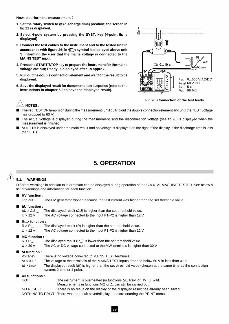
1. Set the rotary switch to ∆∆∆∆∆t (discharge time) position; the screen infig.21 is displayed.
2. Select 4-pole system by pressing the SYST. key (4-point 5s isdisplayed)
3. Connect the test cables to the instrument and to the tested unit inaccordance with figure 26; le symbol is displayed above unitS, informing the user that the mains voltage is connected to theMAINS TEST input.
4. Press the START/STOP key to prepare the instrument for the mainsvoltage cut-out; Ready is displayed after 1s approx.
5. Pull out the double connection element and wait for the result to bedisplayed.
6. Save the displayed result for documentation purposes (refer to theinstructions in chapter 5.2 to save the displayed result).
! NOTES : The red TEST ON lamp is on during the measurement (until pulling out the double connection element and until the TEST voltage
has dropped to 60 V). The actual voltage is displayed during the measurement, and the disconnection voltage (see fig.20) is displayed when the
measurement is finished. ∆t < 0.1 s is displayed under the main result and no voltage is displayed on the right of the display, if the discharge time is less
than 0.1 s.
5. OPERATION
5.1. WARNINGS
Different warnings in addition to information can be displayed during operation of the C.A 6121 MACHINE TESTER. See below alist of warnings and information for each function.
HV function :Trip out : The HV generator tripped because the test current was higher than the set threshold value.
∆∆∆∆∆U function :∆U > ∆Umax : The displayed result (∆U) is higher than the set threshold value.U > 12 V : The AC voltage connected to the input P1-P2 is higher than 12 V.
R10A function :R > Rmax : The displayed result (R) is higher than the set threshold value.U > 12 V : The AC voltage connected to the input P1-P2 is higher than 12 V.
MΩΩΩΩΩ function :R < Rmin : The displayed result (Rins) is lower than the set threshold value.U > 30 V : The AC or DC voltage connected to the MW terminals is higher than 30 V.
∆∆∆∆∆t function :Voltage? :There is no voltage conected to MAINS TEST terminals.∆t < 0.1 s :The voltage at the terminals of the MAINS TEST inputs dropped below 60 V in less than 0.1s.∆t > tmax :The displayed result (∆t) is higher than the set threshold value (chosen at the same time as the connection
system; 2 pole or 4 pole).
All functions :HOT : The instrument is overheated (in functions ∆U, R10A or HV) ⇒ wait.
Measurements in functions MΩ or ∆t can still be carried out.NO RESULT : There is no result on the display or the displayed result has already been saved.NOTHING TO PRINT : There was no result saved/displayed before entering the PRINT menu.
Fig.26. Connection of the test leads
C
U :U :t :R :
inlim
limin
t:
0...600 V AC/DC60 V DC5 s96 M
0...10 s
C2P2C1 P1
600V 250V CAT III
1 - 1.25 - 1.5 kV START / STOP
TEST ONMEM/MR PRINT/RS SET-UP
C.A 6121
+HV
MR10A
tU
ARNOUXCHAUVIN
INSULATION (M )500 - 1000 V
DISCHARGE TIME ( t)
CONTINUITY 12V/>10A ( U,R ) 10A
DIELECTRIC (HV)
LN
PE
!
40
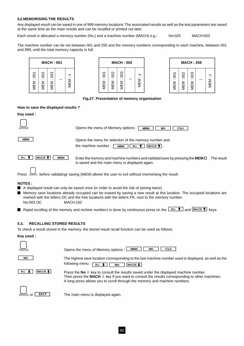
5.2.MEMORISING THE RESULTS
Any displayed result can be saved in one of 999 memory locations. The associated results as well as the test parameters are savedat the same time as the main results and can be recalled or printed out later.
Each result is allocated a memory number (No.) and a machine number (MACH) e.g.: No:025 MACH:003
The machine number can be set between 001 and 255 and the memory numbers corresponding to each machine, between 001and 999, until the total memory capacity is full.
Fig.27. Presentation of memory organisation
How to save the displayed results ?
Key used :
Opens the menu of Memory options :
Opens the menu for selection of the memory number and
the machine number : .
, , Enter the memory and machine numbers and validate/save by pressing the MEM ⇒⇒⇒⇒⇒ . The resultis saved and the main menu is displayed again.
Press before validating/ saving (MEM) allows the user to exit without memorising the result.
NOTES : A displayed result can only be saved once (in order to avoid the risk of storing twice). Memory save locations already occupied can be erased by saving a new result at this location. The occupied locations are
marked with the letters OC and the free locations with the letters FR, next to the memory number.No:003 OC MACH:162
Rapid scrolling of the memory and mchine numbers is done by continuous press on the and keys.
5.3. RECALLING STORED RESULTS
To check a result stored in the memory, the stored result recall function can be used as follows:
Key used :
Opens the menu of Memory options : .
The highest save location corresponding to the last machine number used is displayed, as well as thefollowing menu : .
, Press the No key to consult the results saved under the displayed machine number.Then press the MACH key if you want to consult the results corresponding to other machines.A long press allows you to scroll through the memory and machine numbers.
or EXIT The main menu is displayed again.
MACH : 001 MACH : 002 MACH : 255
ME
M :
001
ME
M :
002
ME
M :
003
ME
M :
x
→
ME
M :
001
ME
M :
002
ME
M :
003
ME
M :
y
→
ME
M :
001
ME
M :
002
ME
M :
003
ME
M :
z
→
41
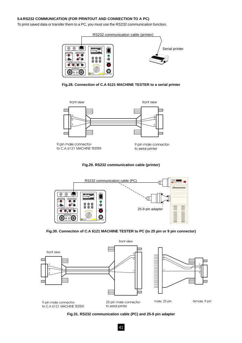
5.4.RS232 COMMUNICATION (FOR PRINTOUT AND CONNECTION TO A PC)
To print saved data or transfer them to a PC, you must use the RS232 communication function.
C2P2C1 P1
TEST
MAINSTEST
REMOTE
CAT III600V
WARNING LAMP 12V~
1 - 1.25 - 1.5 kV START / STOP
TEST ON
230V / 50Hz600VA
RS232C
+ON
OFF
INSULATION (M )Ω DISCHARGE TIME ( t)∆
CONTINUITY 12V/>10A ( U,R )∆ 10A
DIELECTRIC (HV)
600V CAT III
C.A 6121MACHINE TESTER
C.A 6121MACHINE TESTER
HV 500V Rmin=150M
U=513V
9min
MΩMΩ113.5
HVMΩR10A
∆t∆U
ARNOUXCHAUVIN
RS232 communication cable (printer)
Serial printer
Fig.28. Connection of C.A 6121 MACHINE TESTER to a serial printer
9 pin male connector-
to C.A 6121 MACHINE TESTER9 pin male connector-
to serial printer
2 2
33
5 5
front view front view
Fig.29. RS232 communication cable (printer)
C2 P2C1 P1
TEST
MAINSTEST
REMOTE
CAT III600V
WARNING LAMP 12V~
1 - 1.25 - 1.5 kV START / STOP
TEST ON
230V / 50Hz600VA
RS232C
+ON
OFF
INSULATION (M )Ω DISCHARGE TIME ( t)∆
CONTINUITY 12V/>10A ( U,R )∆ 10A
DIELECTRIC (HV)
600V CAT III
MEM/MR PRINT/RS / SET-UP
C.A 6121MACHINE TESTER
C.A 6121MACHINE TESTER
MΩ 500V Rmin=150MΩM 500V Rmin=150MΩ Ω
U=513V
9min60s
MΩMΩ113.5
TIMERRminUn
HVMΩR10A
∆t∆U
ARNOUXCHAUVIN
RS232 communication cable (PC)
25-9 pin adapter
Fig.30. Connection of C.A 6121 MACHINE TESTER to PC (to 25 pin or 9 pin connector)
2
3
3
2
7
5
male, 25 pin female, 9 pin9 pin male connector-
to C.A 6121 MACHINE TESTER
25 pin male connector-
to serial printer
7
3
2
2
3
5
front view
front view
Fig.31. RS232 communication cable (PC) and 25-9 pin adapter
42
How to transfer stored data to serial printer or PC ?
1. Connect the C.A 6121 MACHINE TESTER to the serial printer or to the PC (see figures 28 to 30) using the appropriateRS232 communication cable and adapters.
2. Prepare the printer or the PC for communication.
3. Prepare the C.A 6121 MACHINE TESTER to communicate in the following way:
- Check the baud rate :Press the SET UP key and keep it presses for 2 s approx., until the baud rte selection menu is displayed. Press the BAUD key,then the or keys to set the rate = 300, 600, 1200, 2400 or 4800 bauds (equal to that of the printer or the PC).
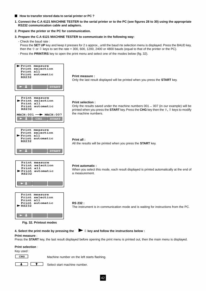
- Press the PRINT/RS key to open the print menu and select one of the modes below (fig. 32).
Print measure :Only the last result displayed will be printed when you press the START key.
Print selection :Only the results saved under the machine numbers 001→ 007 (in our example) will beprinted when you press the START key. Press the CHG key then the , keys to modifythe machine numbers.
Print all :All the results will be printed when you press the START key.
Print automatic :When you select this mode, each result displayed is printed automatically at the end ofa measurement.
RS 232 :The instrument is in communication mode and is waiting for instructions from the PC.
4. Select the print mode by pressing the key and follow the instructions below :
Print measure :Press the START key, the last result displayed before opening the print menu is printed out, then the main menu is displayed.
Print selection :Key used :
Machine number on the left starts flashing.
, Select start machine number.
Print measurePrint selection
Print automaticPrint all
RS232
START
Print measurePrint selection
Print automaticPrint all
RS232
Print measurePrint selection
Print automaticPrint all
RS232
START
Print measurePrint selection
Print automaticPrint all
RS232
MACH:001 MACH:007
STARTCHG
Fig. 32. Printout modes
Print measurePrint selection
Print automaticPrint all
RS232
43
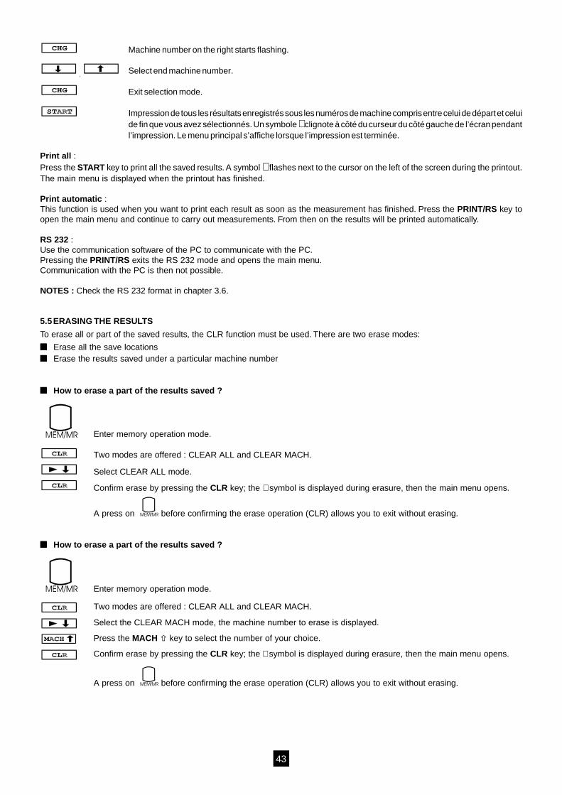
Machine number on the right starts flashing.
, Select end machine number.
Exit selection mode.
Impression de tous les résultats enregistrés sous les numéros de machine compris entre celui de départ et celuide fin que vous avez sélectionnés. Un symbole ∗ clignote à côté du curseur du côté gauche de l’écran pendantl’impression. Le menu principal s’affiche lorsque l’impression est terminée.
Print all :Press the START key to print all the saved results. A symbol ∗ flashes next to the cursor on the left of the screen during the printout.The main menu is displayed when the printout has finished.
Print automatic :This function is used when you want to print each result as soon as the measurement has finished. Press the PRINT/RS key toopen the main menu and continue to carry out measurements. From then on the results will be printed automatically.
RS 232 :Use the communication software of the PC to communicate with the PC.Pressing the PRINT/RS exits the RS 232 mode and opens the main menu.Communication with the PC is then not possible.
NOTES : Check the RS 232 format in chapter 3.6.
5.5ERASING THE RESULTS
To erase all or part of the saved results, the CLR function must be used. There are two erase modes:
Erase all the save locations Erase the results saved under a particular machine number
How to erase a part of the results saved ?
Enter memory operation mode.
Two modes are offered : CLEAR ALL and CLEAR MACH.
Select CLEAR ALL mode.
Confirm erase by pressing the CLR key; the ∗ symbol is displayed during erasure, then the main menu opens.
A press on before confirming the erase operation (CLR) allows you to exit without erasing.
How to erase a part of the results saved ?
Enter memory operation mode.
Two modes are offered : CLEAR ALL and CLEAR MACH.
Select the CLEAR MACH mode, the machine number to erase is displayed.
Press the MACH key to select the number of your choice.
Confirm erase by pressing the CLR key; the ∗ symbol is displayed during erasure, then the main menu opens.
A press on before confirming the erase operation (CLR) allows you to exit without erasing.
44
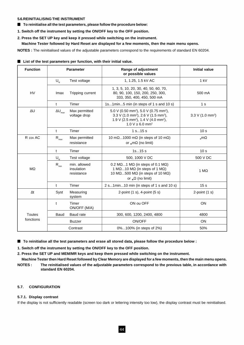
5.6.REINITIALISING THE INSTRUMENT
To reinitialise all the test parameters, please follow the procedure below:
1. Switch off the instrument by setting the ON/OFF key to the OFF position.
2. Press the SET UP key and keep it pressed while switching on the instrument.
Machine Tester followed by Hard Reset are displayed for a few moments, then the main menu opens.
NOTES : The reinitialised values of the adjustable parameters correspond to the requirements of standard EN 60204.
List of the test parameters per function, with their initial value.
Function Parameter Range of adjustment Initial valueor possible values
UN Test voltage 1, 1.25, 1.5 kV AC 1 kV
1, 3, 5, 10, 20, 30, 40, 50, 60, 70,HV Imax Tripping current 80, 90, 100, 150, 200, 250, 300, 500 mA
333, 350, 400, 450, 500 mA
t Timer 1s...1min...5 min (in steps of 1 s and 10 s) 1 s
∆U ∆Umax Max permitted 5.0 V (0.50 mm2), 5.0 V (0.75 mm2),voltage drop 3.3 V (1.0 mm2), 2.6 V (1.5 mm2), 3.3 V (1.0 mm2)
1.9 V (2.5 mm2), 1.4 V (4.0 mm2),1.0 V ≥ 6.0 mm2
t Timer 1 s...15 s 10 s
R 10A AC Rmax Max permitted 10 mΩ...1000 mΩ (in steps of 10 mΩ) *mΩresistance or *mΩ (no limit)
t Timer 1s...15 s 10 s
UN Test voltage 500, 1000 V DC 500 V DC
Rmin min. allowed 0.2 MΩ...1 MΩ (in steps of 0.1 MΩ)MΩ insulation 1 MΩ...10 MΩ (in steps of 1 MΩ) 1 MΩ
resistance 10 MΩ...500 MΩ (in steps of 10 MΩ)or *Ω (no limit)
t Timer 2 s...1min...10 min (in steps of 1 s and 10 s) 15 s
∆t Syst Measuring 2-point (1 s), 4-point (5 s) 2-point (1 s)system
t Timer ON ou OFF ONON/OFF (M/A)
Toutes Baud Baud rate 300, 600, 1200, 2400, 4800 4800fonctions Buzzer ON/OFF ON
Contrast 0%...100% (in steps of 2%) 50%
To reinitialise all the test parameters and erase all stored data, please follow the procedure below :
1. Switch off the instrument by setting the ON/OFF key to the OFF position.
2. Press the SET UP and MEM/MR keys and keep them pressed while switching on the instrument.
Machine Tester then Hard Reset followed by Clear Memory are displayed for a few moments, then the main menu opens.
NOTES : The reinitialised values of the adjustable parameters correspond to the previous table, in accordance withstandard EN 60204.
5.7. CONFIGURATION
5.7.1. Display contrast
If the display is not sufficiently readable (screen too dark or lettering intensity too low), the display contrast must be reinitialised.
45
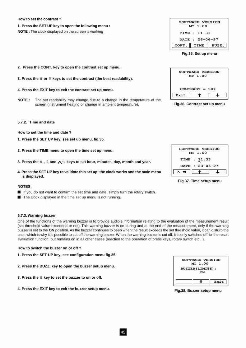
How to set the contrast ?
1. Press the SET UP key to open the following menu :
NOTE : The clock displayed on the screen is working
2. Press the CONT. key to open the contrast set up menu.
3. Press the or keys to set the contrast (the best readability).
4. Press the EXIT key to exit the contrast set up menu.
NOTE : The set readability may change due to a change in the temperature of thescreen (instrument heating or change in ambient temperature).
5.7.2. Time and date
How to set the time and date ?
1. Press the SET UP key, see set up menu, fig.35.
2. Press the TIME menu to open the time set up menu:
3. Press the , and keys to set hour, minutes, day, month and year.
4. Press the SET UP key to validate this set up; the clock works and the main menuis displayed.
NOTES :
If you do not want to confirm the set time and date, simply turn the rotary switch. The clock displayed in the time set up menu is not running.
5.7.3. Warning buzzer
One of the functions of the warning buzzer is to provide audible information relating to the evaluation of the measurement result(set threshold value exceeded or not). This warning buzzer is on during and at the end of the measurement, only if the warningbuzzer is set to the ON position. As the buzzer continues to beep when the result exceeds the set threshold value, it can disturb theuser, which is why it is possible to cut off the warning buzzer. When the warning buzzer is cut off, it is only switched off for the resultevaluation function, but remains on in all other cases (reaction to the operation of press keys, rotary switch etc...).
How to switch the buzzer on or off ?
1. Press the SET UP key, see configuration menu fig.35.
2. Press the BUZZ. key to open the buzzer setup menu.
3. Press the key to set the buzzer to on or off.
4. Press the EXIT key to exit the buzzer setup menu.
SOFTWARE VERSIONMT 1.00
TIME : 11:33
DATE : 26-06-97
CONT. TIME BUZZ.
Fig.35. Set up menu
Fig.36. Contrast set up menu
SOFTWARE VERSIONMT 1.00
CONTRAST = 50%
Exit
Fig.37. Time setup menu
SOFTWARE VERSIONMT 1.00
DATE : 23-06-97
TIME : 11:33
Fig.38. Buzzer setup menu
SOFTWARE VERSIONMT 1.00
BUZZER(LIMITS):ON
Exit
46
5.7.4. Baud rate
How to set the baud rate ?
1. Press the SET UP key and keep it pressed for approx. 2 s until the Baud menu isdisplayed (see fig.39) :
2. Press the BAUD key to open the baud rate setup menu (see fig. 40)
3. Press the and keys to set the rate to 300, 600, 1200, 2400, or 4800 bauds.
4. Press the EXIT key to return to the main menu.
5.8. SOUND SIGNALS
There are 3 different types of sound signals :
a) Continuous signal : The displayed result is outside the set limitb) Beep signal : Signals pressing of a key or turning of rotary switchc) Beep-beep signal : End of the timer or of a recording, erasing, printout or transmission to a PC.
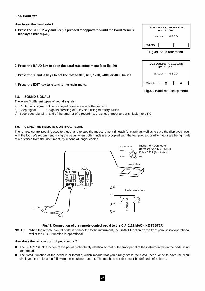
5.9. USING THE REMOTE CONTROL PEDAL
The remote control pedal is used to trigger and to stop the measurement (in each function), as well as to save the displayed resultwith the foot. We recommend using the pedal when both hands are occupied with the test probes, or when tests are being madeat a distance from the instrument, by means of longer cables.
C2P2C1 P1
600V 250V CAT III600V
TEST
MAINSTEST
REMOTE WARNING LAMP 12V~
1 - 1.25 - 1.5 kV START / STOP
TEST ON
230V / 50Hz500VA
RS232C
MEM/MR PRINT/RS SET-UP
C.A 6121MACHINE TESTER
+ON
OFF
HVM
R10A
tU
ARNOUXCHAUVIN
INSULATION (M )500 - 1000 V
DISCHARGE TIME ( t)
CONTINUITY 12V/>10A ( U,R ) 10A
DIELECTRIC (HV)
START/STOP
IDENT
SAVEGND
Instrument connector(female) type MAB 6100DIN 45322 (front view)
SA
VE
STA
RT
/STO
P
Pedal switches
1
23
4
5
2
1
3
5
front view
Fig.41. Connection of the remote control pedal to the C.A 6121 MACHINE TESTER
NOTE : When the remote control pedal is connected to the instrument, the START function on the front panel is not operational,whilst the STOP function is operational.
How does the remote control pedal work ?
The START/STOP function of the pedal is absolutely identical to that of the front panel of the instrument when the pedal is notconnected.
The SAVE function of the pedal is automatic, which means that you simply press the SAVE pedal once to save the resultdisplayed in the location following the machine number. The machine number must be defined beforehand.
Fig.39. Baud rate menu
SOFTWARE VERSIONMT 1.00
BAUD : 4800
BAUD
Fig.40. Baud rate setup menu
SOFTWARE VERSIONMT 1.00
BAUD : 4800
Exit
47
C2P2C1 P1
600V 250V CAT III600V
TEST
MAINSTEST
REMOTE WARNING LAMP 12V~
1 - 1.25 - 1.5 kV START / STOP
TEST ON
230V / 50Hz500VA
RS232C
MEM/MR PRINT/RS SET-UP
C.A 6121MACHINE TESTER
+ON
OFF
HVM
R10A
tU
ARNOUXCHAUVIN
INSULATION (M )500 - 1000 V
DISCHARGE TIME ( t)
CONTINUITY 12V/>10A ( U,R ) 10A
DIELECTRIC (HV)
12 3 4
5
TEST
READY
Instrument connector(female) type MAB 5100DIN 41524 (front view)and internal instrumentcircuitryfront view
The procedure to follow is as follows :
1. Connect the remote control pedal in accordance with fig 41.
2. Record a first measurement at the desired memory location (memory number and machine number) with the keys onthe keyboard (see § 5.2).
3. Carry out the next test by pressing the START/STOP pedal.
4. Save the results by pressing the SAVE pedal.
The following window (fig. 42) is displayed for a moment (if for example an HT testhas been carried out) :
Then the main menu is displayed again. Continue the measurements.
Technical specifications of the pedal :Cable length : 10 mCommands : START/STOP, SAVECase : metallicWeight : 2 kgDimensions (W x H x D) : 300 x 175 x 55 mm
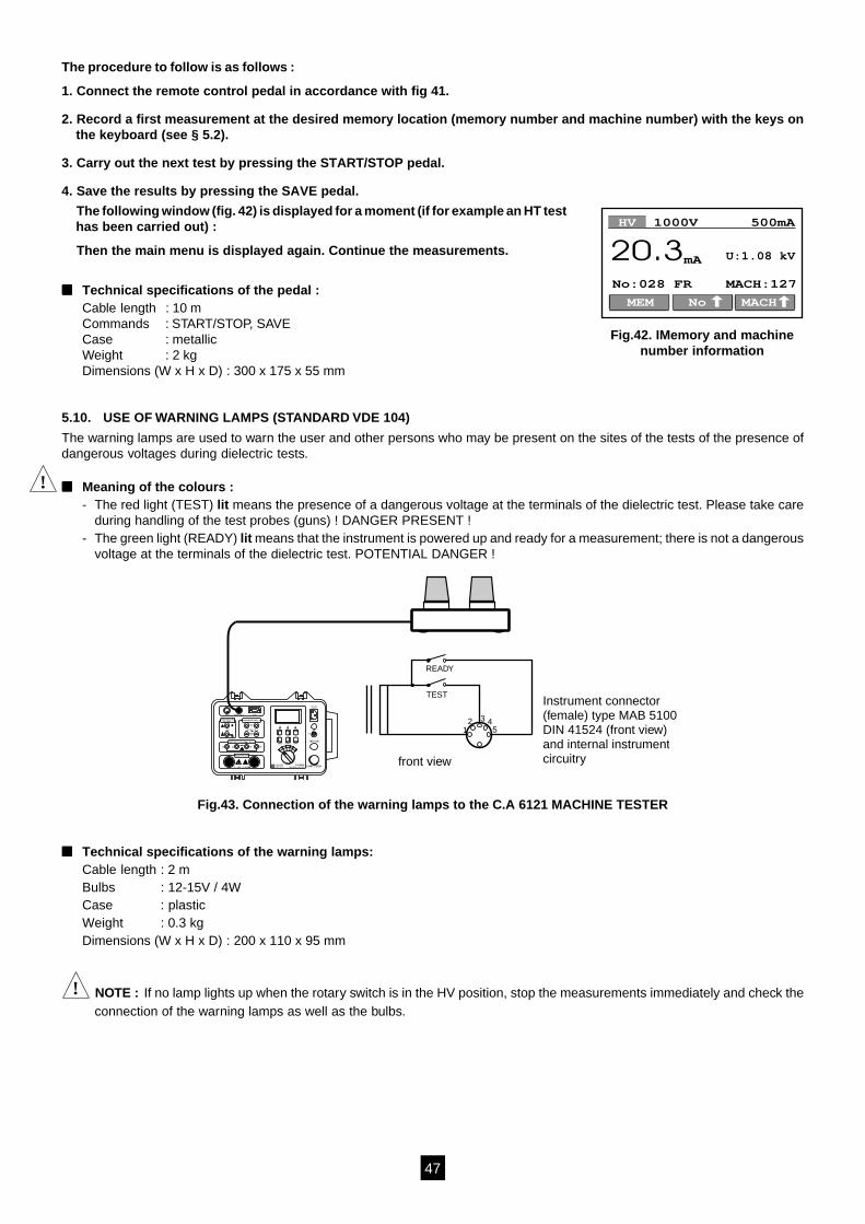
5.10. USE OF WARNING LAMPS (STANDARD VDE 104)
The warning lamps are used to warn the user and other persons who may be present on the sites of the tests of the presence ofdangerous voltages during dielectric tests.
Meaning of the colours :- The red light (TEST) lit means the presence of a dangerous voltage at the terminals of the dielectric test. Please take care
during handling of the test probes (guns) ! DANGER PRESENT !- The green light (READY) lit means that the instrument is powered up and ready for a measurement; there is not a dangerous
voltage at the terminals of the dielectric test. POTENTIAL DANGER !
Fig.43. Connection of the warning lamps to the C.A 6121 MACHINE TESTER
Technical specifications of the warning lamps:Cable length : 2 mBulbs : 12-15V / 4WCase : plasticWeight : 0.3 kgDimensions (W x H x D) : 200 x 110 x 95 mm
! NOTE : If no lamp lights up when the rotary switch is in the HV position, stop the measurements immediately and check theconnection of the warning lamps as well as the bulbs.
Fig.42. IMemory and machinenumber information
HV 1000V 500mA
mA20.3
MACHNoMEM
MACH:127No:028 FR
U:1.08 kV
!
48
! 6. MAINTENANCE !
6.1. USUAL CLEANING
Use a soft cloth slightly moistened with soapy water to clean the surface of the C.A 6121 MACHIN TESTER and allow theinstrument to dry completely after cleaning (2 h).Do not use liquids based on alcohol, oil or hydrocarbons !Do not pour cleaning liquid on the instrument !
6.2. REPLACING THE FUSES (FOR PROPERLY QUALIFIED MAINTENANCE PERSONNEL ONLY !)
If the instrument has any faulty function of any kind, have the four fuses checked by an approved maintenance technician.Refer to chapter 3.6 to know the function of each fuse.Only use original fuses, like those specified in chapter 3.6.!
! Unplug all the test cables and power supply leads before opening the instrument.
Dangerous voltages may be present in the instrument.
Only a qualified maintenance technician cn carry out replacement.
Position of each fuse :F1 : MC PCB (power supply card)F2 : SMC PCB (power supply card)F3 : Mains filter PCBF4 : Test terminal filter PCB
6.3METROLOGICAL CHECK
! It is essential that all measurement instruments are regularly calibrated.For checking and calibration of your instrument, please contact our accredited laboratories (list on request) or the Chauvin Arnouxsubsidiary or Agent in your country.
6.4. AFTER SALES SERVICE
For maintenance operations, only use specified spare parts. The manufacturer will not be held responsible for any accidentoccurring following a repair done other than by its After Sales Service or approved repairers.
MaintenanceRepairs under or out of guarantee : please return the product to your distributor.

49
7. TO ORDER
C.A 6121 MACHINE TESTER (GB) ........................................................................................................................ P01.1456.02
C.A 6121 MACHINE TESTER (EURO) ................................................................................................................... P01.1456.01
Standard supply :- 1 power supply lead- 2 dielectric test guns (probes) with cable 2 m- 2 continuity test leads, 2.5 m (1 red, 1 black)- 2 insulation test leads, 3 m (1 red, 1 black)- 2 crocodile clips (1 red, 1 black)- 1 test prod, red- 1 discharge time cable (for Continental Europe = EURO or for Great Britain = GB)- 1 bag for the accessories- 1 user manual in 5 languages
ACCESSORIES
PC software “ C.A 6121 TRANSFER ” Windows (supplied with cable DB9M-DB25F + adaptater DB9F-DB25M) ..... P01.1019.15
Serial printer (supplied with cable DB9M-DB9M) ......................................................................................................... P01.1029.01
Remote control pedal .................................................................................................................................................... P01.1019.16
Warning lamps (green / red)) ........................................................................................................................................ P01.1019.17
2 dielectric test guns with cable 6 m ............................................................................................................................. P01.1019.18
SPARE PARTS
1 rigid bag for accessories ............................................................................................................................................P01.2980.31
2 dielectric test guns with cable 2 m ............................................................................................................................. P01.1019.19
1 continuity test lead, 2.5 m (red) ................................................................................................................................. P01.2951.40
1 continuity test lead, 2.5 m (black) .............................................................................................................................. P01.2951.37
2 safety leads, 3 m (1 red, 1 black) ............................................................................................................................... P01.2950.97
2 test prods (1 red, 1 black) .......................................................................................................................................... P01.1018.55
2 crocodile clips (1 red, 1 black) ................................................................................................................................... P01.1018.48
1 discharge time cable (EURO) .................................................................................................................................... P01.2951.41
1 discharge time cable (GB) ......................................................................................................................................... P01.2951.42
Cable for PC RS232 DB9M-DB25F .............................................................................................................................. P01.2951.38
Cable for printer RS232 DB9M-DB9M ..........................................................................................................................P01.2951.39
1 adapter DB9F-DB25M ............................................................................................................................................... P01.1018.41
5 rolls of paper for serial printer .................................................................................................................................... P01.1019.07
10 fuses 20 A-600 V, 10.3 x 38F ................................................................................................................................... P01.2970.30
10 fuses 1 A-250 V, 5 x 20T .......................................................................................................................................... P01.2970.31
10 fuses 4 A-250 V, 5 x 20T .......................................................................................................................................... P01.2970.32
10 fuses 0,2 A-250 V, 6.3 x 32F .................................................................................................................................... P01.2970.33