Techniques for PIR-based motion detection
43
Techniques for PIR-based motion detection Miro Oljaca Building Automation Systems
Transcript of Techniques for PIR-based motion detection
Techniques for PIR-based motion detection
Miro Oljaca
Building Automation Systems

PIR operation and limitation
2
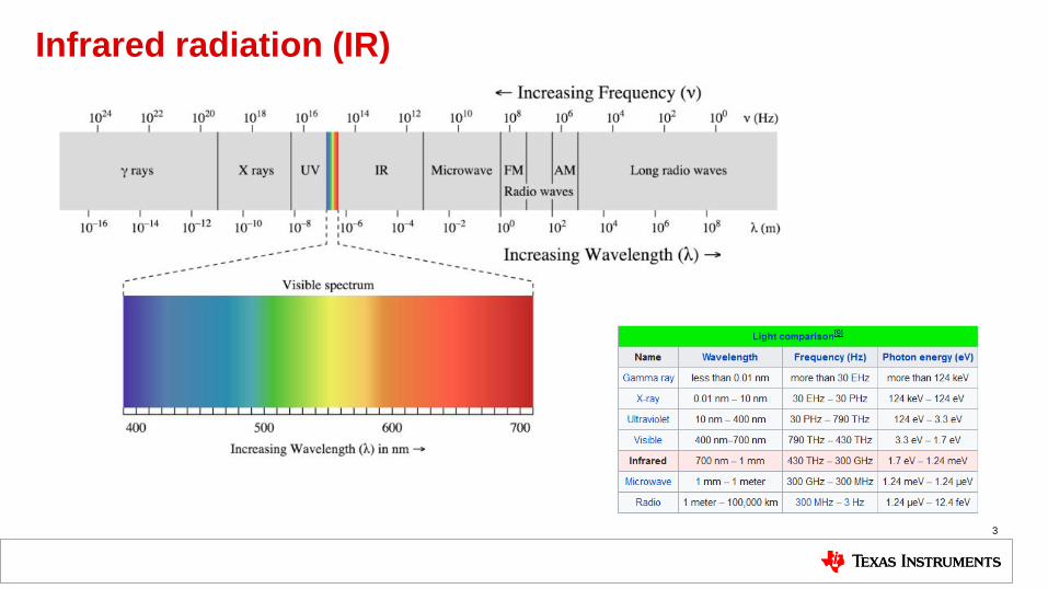
Infrared radiation (IR)
3
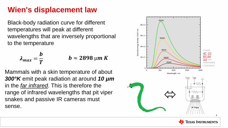
Wien's displacement law
4
Mammals with a skin temperature of about
300°K emit peak radiation at around 10 μm
in the far infrared. This is therefore the
range of infrared wavelengths that pit viper
snakes and passive IR cameras must
sense.
Black-body radiation curve for different
temperatures will peak at different
wavelengths that are inversely proportional
to the temperature
𝒃 ≈ 𝟐𝟖𝟗𝟖 µ𝒎 𝑲 𝝀𝒎𝒂𝒙 =𝒃
𝑻
Credit:
4C, CC
BY-SA
3.0, via
Wikimedia
Commons
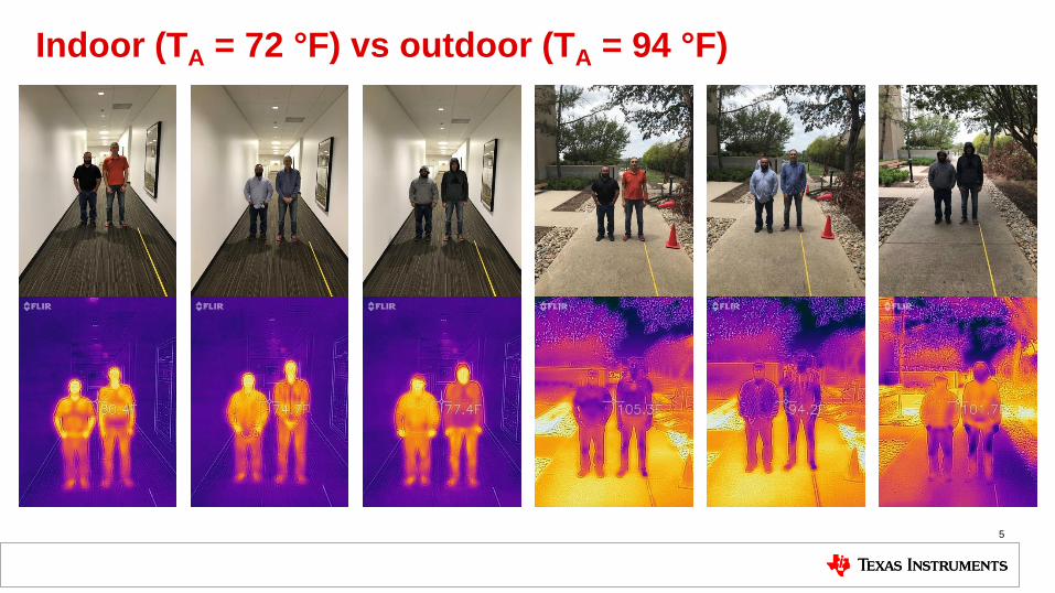
Indoor (TA = 72 °F) vs outdoor (TA = 94 °F)
5
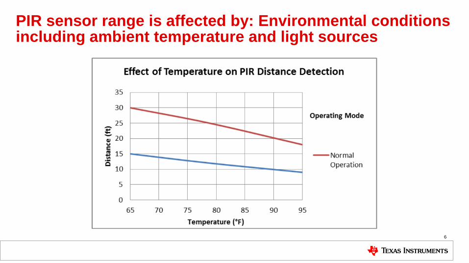
PIR sensor range is affected by: Environmental conditions including ambient temperature and light sources
6
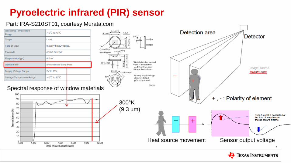
Pyroelectric infrared (PIR) sensor
7
300°K
(9.3 µm)
Part: IRA-S210ST01, courtesy Murata.com
Spectral response of window materials
Heat source movement Sensor output voltage
Image source:
Murata.com
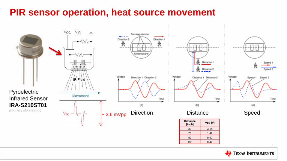
PIR sensor operation, heat source movement
8
~ 3.6 mVpp
Pyroelectric
Infrared Sensor
IRA-S210ST01 (courtesy Murata.com)
Direction Distance Speed
Distance
[inch] Vpp [v]
30 3,14
70 1,42
90 0,92
130 0,42

Noise reduction techniques
9
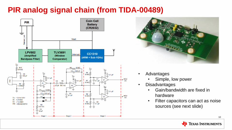
PIR analog signal chain (from TIDA-00489)
10
• Advantages
• Simple, low power
• Disadvantages
• Gain/bandwidth are fixed in
hardware
• Filter capacitors can act as noise
sources (see next slide)
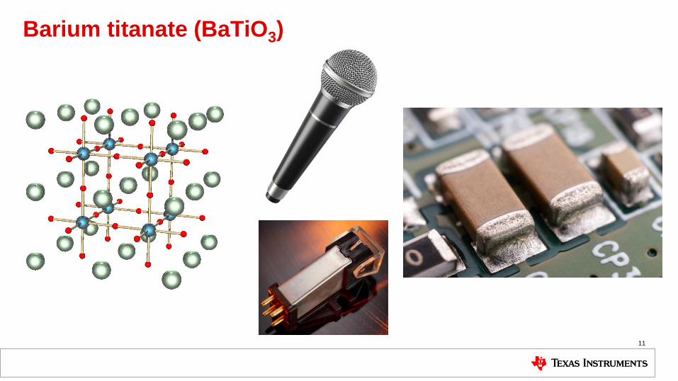
Barium titanate (BaTiO3)
11
PIR Sensor
+3.3V
+
-
+
-
+VRef
+
-
+VRH
+
-
+VRL
MSP430
+3.3V
GPIO
GPIO
GPIO
+3.3V
GPIO
GainBand-pass filter
GainBand-pass filter
Comparator BoosterPack
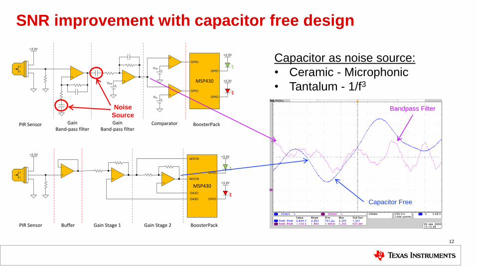
SNR improvement with capacitor free design
12
PIR Sensor
MSP430
+3.3VADCIN
GPIO
+3.3V
GPIO
+3.3V
+
-
+
-
+
-
BoosterPackGain Stage 2Gain Stage 1Buffer
ADCIN
OA2O
OA3O
Noise
Source
Capacitor as noise source:
• Ceramic - Microphonic
• Tantalum - 1/f3
Bandpass Filter
Capacitor Free
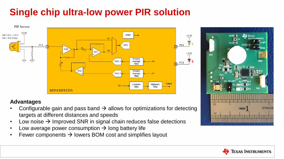
Single chip ultra-low power PIR solution
Advantages
• Configurable gain and pass band allows for optimizations for detecting
targets at different distances and speeds
• Low noise Improved SNR in signal chain reduces false detections
• Low average power consumption long battery life
• Fewer components lowers BOM cost and simplifies layout
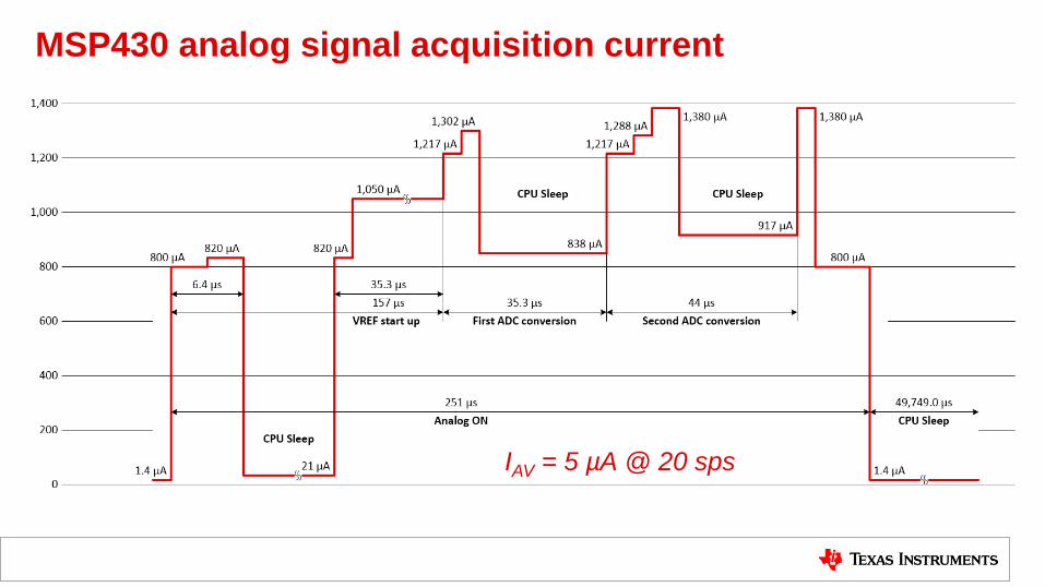
MSP430 analog signal acquisition current
IAV = 5 µA @ 20 sps
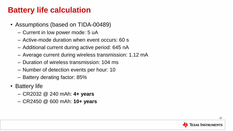
Battery life calculation
• Assumptions (based on TIDA-00489)
– Current in low power mode: 5 uA
– Active-mode duration when event occurs: 60 s
– Additional current during active period: 645 nA
– Average current during wireless transmission: 1.12 mA
– Duration of wireless transmission: 104 ms
– Number of detection events per hour: 10
– Battery derating factor: 85%
• Battery life
– CR2032 @ 240 mAh: 4+ years
– CR2450 @ 600 mAh: 10+ years
15
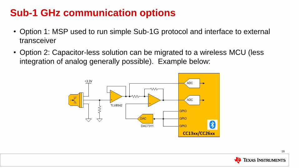
Sub-1 GHz communication options
• Option 1: MSP used to run simple Sub-1G protocol and interface to external
transceiver
• Option 2: Capacitor-less solution can be migrated to a wireless MCU (less
integration of analog generally possible). Example below:
16
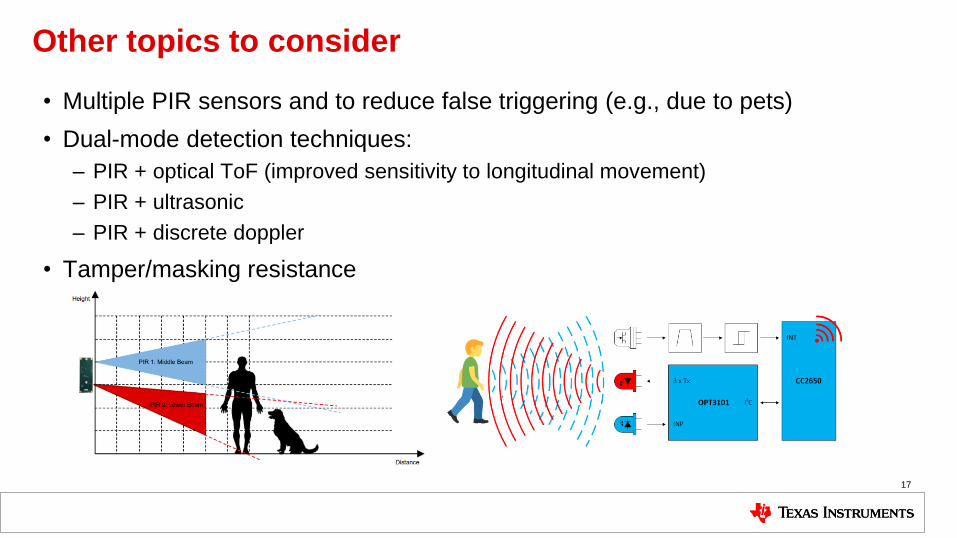
Other topics to consider
• Multiple PIR sensors and to reduce false triggering (e.g., due to pets)
• Dual-mode detection techniques:
– PIR + optical ToF (improved sensitivity to longitudinal movement)
– PIR + ultrasonic
– PIR + discrete doppler
• Tamper/masking resistance
17
Advanced motion detection
• Multiple PIR
• PIR + camera
• PIR + ToF
• PIR + Ultrasonic
• PIR + uWave 18
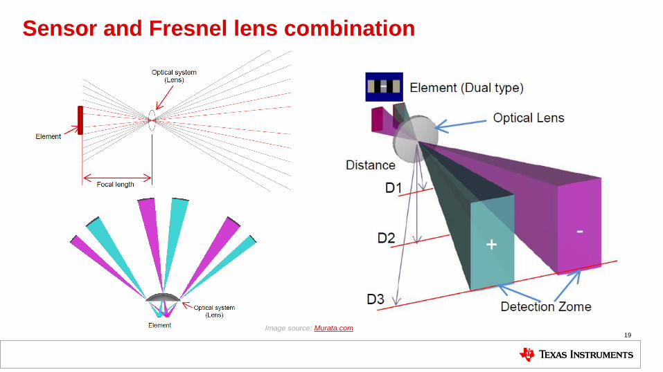
Sensor and Fresnel lens combination
19 Image source: Murata.com
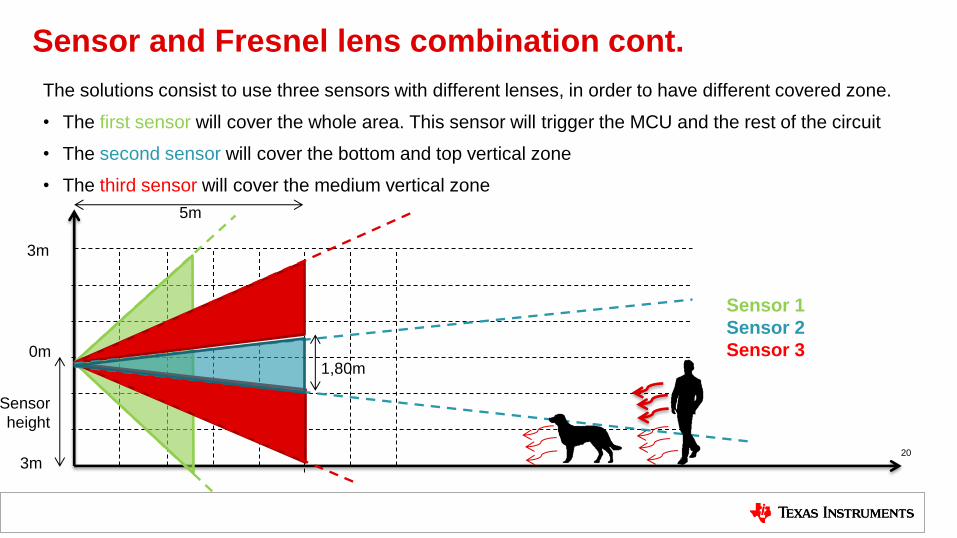
Sensor and Fresnel lens combination cont.
The solutions consist to use three sensors with different lenses, in order to have different covered zone.
• The first sensor will cover the whole area. This sensor will trigger the MCU and the rest of the circuit
• The second sensor will cover the bottom and top vertical zone
• The third sensor will cover the medium vertical zone
20
20
1,80m
Sensor 1
Sensor 2
Sensor 3
5m
0m
3m
3m
Sensor
height
Advanced motion detection
• Multiple PIR
• PIR + camera
• PIR + ToF
• PIR + Ultrasonic
• PIR + uWave 21
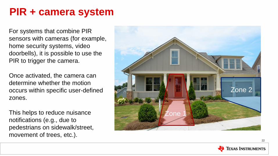
PIR + camera system
22
Zone 1
Zone 2
For systems that combine PIR
sensors with cameras (for example,
home security systems, video
doorbells), it is possible to use the
PIR to trigger the camera.
Once activated, the camera can
determine whether the motion
occurs within specific user-defined
zones.
This helps to reduce nuisance
notifications (e.g., due to
pedestrians on sidewalk/street,
movement of trees, etc.).
Advanced motion detection
• Multiple PIR
• PIR + camera
• PIR + ToF
• PIR + Ultrasonic
• PIR + discrete Doppler 23
BEST DIRECTION
PO
OR
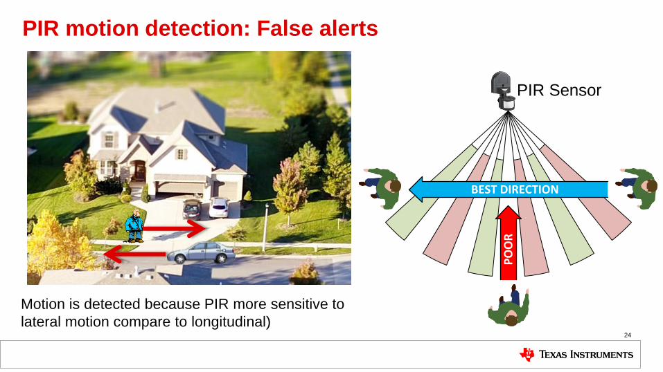
PIR motion detection: False alerts
24
Motion is detected because PIR more sensitive to
lateral motion compare to longitudinal)
PIR Sensor
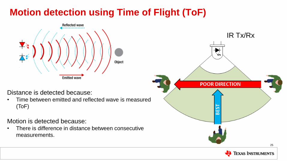
Motion detection using Time of Flight (ToF)
25
IR Tx/Rx
Distance is detected because: • Time between emitted and reflected wave is measured
(ToF)
Motion is detected because: • There is difference in distance between consecutive
measurements.
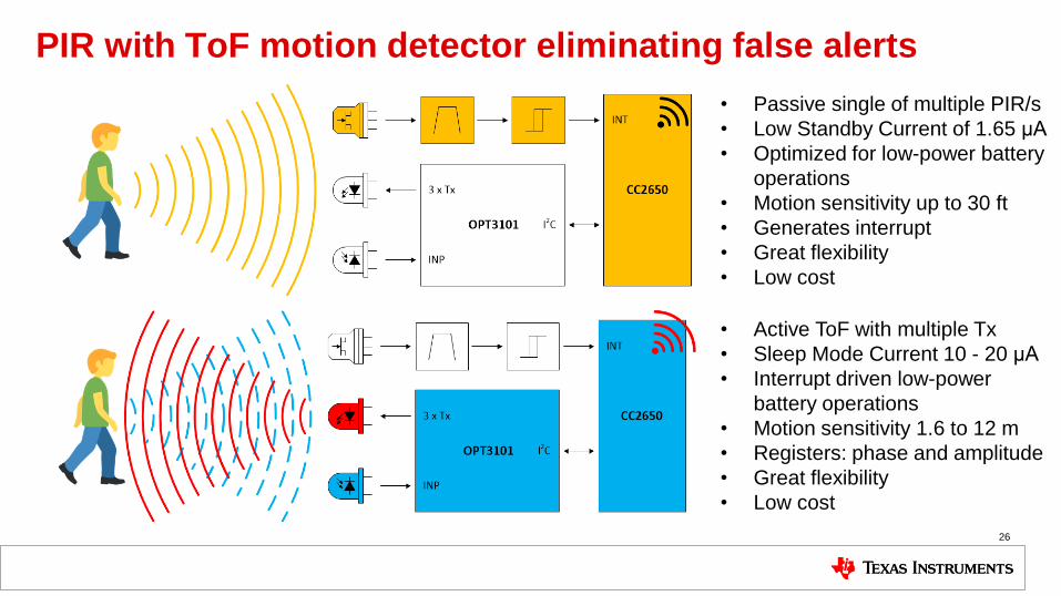
PIR with ToF motion detector eliminating false alerts
26
• Passive single of multiple PIR/s
• Low Standby Current of 1.65 μA
• Optimized for low-power battery
operations
• Motion sensitivity up to 30 ft
• Generates interrupt
• Great flexibility
• Low cost
• Active ToF with multiple Tx
• Sleep Mode Current 10 - 20 μA
• Interrupt driven low-power
battery operations
• Motion sensitivity 1.6 to 12 m
• Registers: phase and amplitude
• Great flexibility
• Low cost
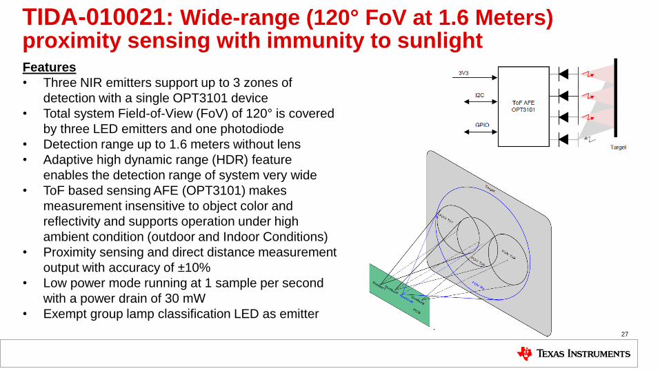
Features
• Three NIR emitters support up to 3 zones of
detection with a single OPT3101 device
• Total system Field-of-View (FoV) of 120° is covered
by three LED emitters and one photodiode
• Detection range up to 1.6 meters without lens
• Adaptive high dynamic range (HDR) feature
enables the detection range of system very wide
• ToF based sensing AFE (OPT3101) makes
measurement insensitive to object color and
reflectivity and supports operation under high
ambient condition (outdoor and Indoor Conditions)
• Proximity sensing and direct distance measurement
output with accuracy of ±10%
• Low power mode running at 1 sample per second
with a power drain of 30 mW
• Exempt group lamp classification LED as emitter
TIDA-010021: Wide-range (120° FoV at 1.6 Meters) proximity sensing with immunity to sunlight
27

Advanced motion detection
• Multiple PIR
• PIR + camera
• PIR + ToF
• PIR + Ultrasonic
• PIR + discrete Doppler 28
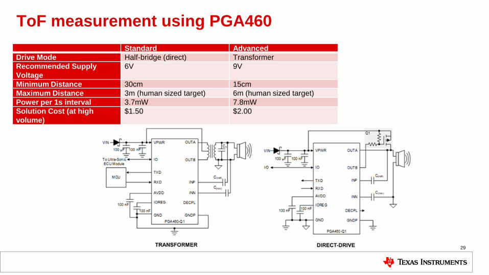
ToF measurement using PGA460
29
Standard Advanced
Drive Mode Half-bridge (direct) Transformer
Recommended Supply
Voltage
6V 9V
Minimum Distance 30cm 15cm
Maximum Distance 3m (human sized target) 6m (human sized target)
Power per 1s interval 3.7mW 7.8mW
Solution Cost (at high
volume)
$1.50 $2.00
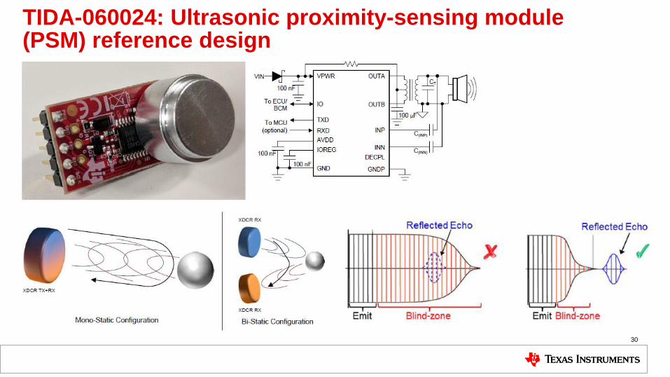
TIDA-060024: Ultrasonic proximity-sensing module (PSM) reference design
30
Advanced motion detection
• Multiple PIR
• PIR + camera
• PIR + ToF
• PIR + Ultrasonic
• PIR + discrete Doppler 31
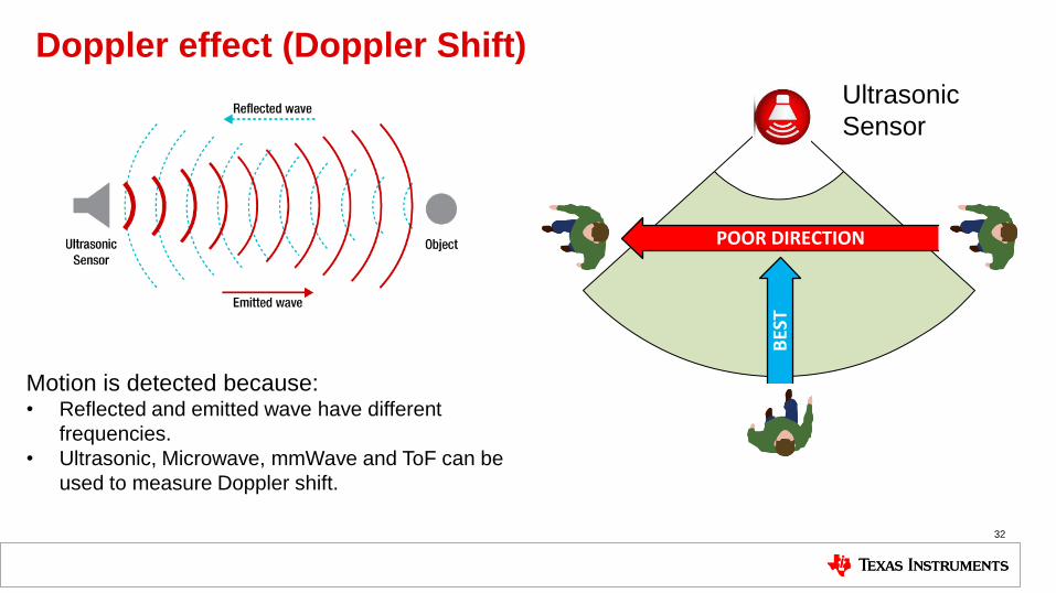
Doppler effect (Doppler Shift)
32
POOR DIRECTION
BES
T
Ultrasonic
Sensor
Motion is detected because: • Reflected and emitted wave have different
frequencies.
• Ultrasonic, Microwave, mmWave and ToF can be
used to measure Doppler shift.
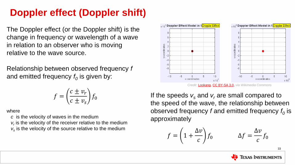
Doppler effect (Doppler shift)
33
The Doppler effect (or the Doppler shift) is the
change in frequency or wavelength of a wave
in relation to an observer who is moving
relative to the wave source.
Relationship between observed frequency f
and emitted frequency f0 is given by:
If the speeds vs and vr are small compared to
the speed of the wave, the relationship between
observed frequency f and emitted frequency f0 is
approximately
𝑓 =𝑐 ± 𝑣𝑟𝑐 ± 𝑣𝑠
𝑓0
where
c is the velocity of waves in the medium
vr is the velocity of the receiver relative to the medium
vs is the velocity of the source relative to the medium
𝑓 = 1 +Δ𝑣
𝑐𝑓0 Δ𝑓 =
Δ𝑣
𝑐𝑓0
Credit: Lookang, CC BY-SA 3.0, via Wikimedia Commons
Intermediate frequency (IF)
34
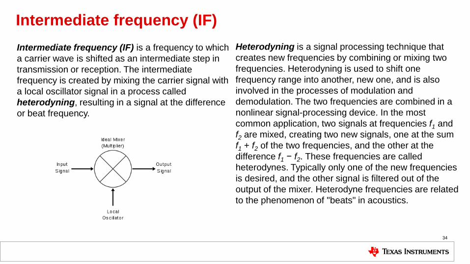
Intermediate frequency (IF) is a frequency to which
a carrier wave is shifted as an intermediate step in
transmission or reception. The intermediate
frequency is created by mixing the carrier signal with
a local oscillator signal in a process called
heterodyning, resulting in a signal at the difference
or beat frequency.
Heterodyning is a signal processing technique that
creates new frequencies by combining or mixing two
frequencies. Heterodyning is used to shift one
frequency range into another, new one, and is also
involved in the processes of modulation and
demodulation. The two frequencies are combined in a
nonlinear signal-processing device. In the most
common application, two signals at frequencies f1 and
f2 are mixed, creating two new signals, one at the sum
f1 + f2 of the two frequencies, and the other at the
difference f1 − f2. These frequencies are called
heterodynes. Typically only one of the new frequencies
is desired, and the other signal is filtered out of the
output of the mixer. Heterodyne frequencies are related
to the phenomenon of "beats" in acoustics.
Intermediate frequency (IF) cont.
35
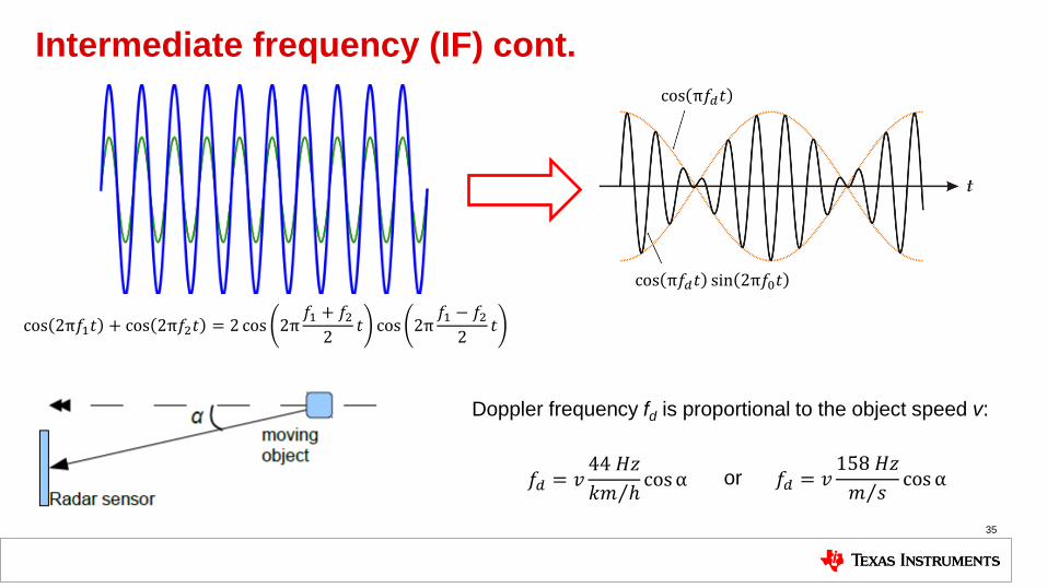
cos 2π𝑓1𝑡 + cos 2π𝑓2𝑡 = 2 cos 2π𝑓1 + 𝑓2
2𝑡 cos 2π
𝑓1 − 𝑓22
𝑡
𝑓𝑑 = 𝑣44 𝐻𝑧
𝑘𝑚 ℎ cosα 𝑓𝑑 = 𝑣
158 𝐻𝑧
𝑚 𝑠 cos α
Doppler frequency fd is proportional to the object speed v:
or
cos π𝑓𝑑𝑡
cos π𝑓𝑑𝑡 sin 2π𝑓0𝑡
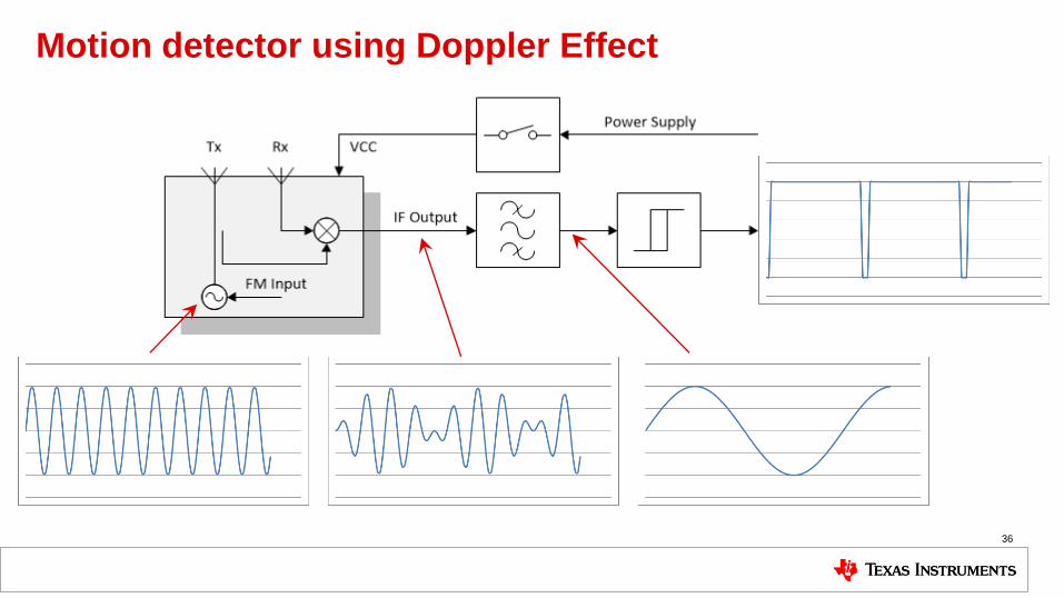
Motion detector using Doppler Effect
36
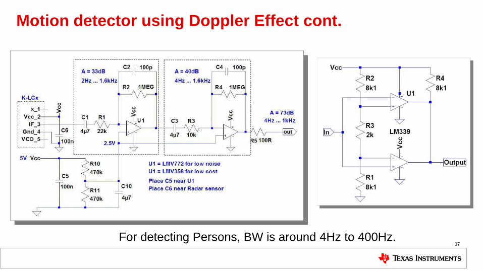
Motion detector using Doppler Effect cont.
37 For detecting Persons, BW is around 4Hz to 400Hz.
Comparing different motion detector technologies
38
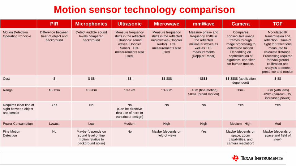
Motion sensor technology comparison
PIR Microphonics Ultrasonic Microwave mmWave Camera TOF
Motion Detection
Operating Principle
Difference between
heat of object and
background
Detect audible sound
levels compared
background
Measure frequency
shifts in the reflected
ultrasonic sound
waves (Doppler
Sonar). TOF
measurements also
used.
Measure frequency
shifts in the reflected
microwaves (Doppler
Radar). TOF
measurements also
used.
Measure phase and
frequency shifts in
the reflected
millimeter waves as
well as TOF
measurements
(Doppler Radar)
Compares
consecutive image
frames through
image processing to
determine motion.
Depending on
sophistication of
algorithm, can filter
for human motion.
Modulated IR
transmission and
reflection. Time of
flight for reflections
measured to
calculate distance.
Processing required
for background
calibration and
analysis to detect
presence and motion
Cost $ $-$$ $$ $$-$$$ $$$$ $$-$$$$ (application
dependent)
$-$$
Range 10-12m 10-20m 10-12m 10-30m ~10m (fine motion)
50m+ (broad motion)
30m+ ~6m (with lens)
<20m (narrow FOV,
increased power)
Requires clear line of
sight between object
and sensor
Yes No No
(Can be directive
thru use of horn or
transducer design)
No No Yes Yes
Power Consumption Lowest Low Medium High High Medium - High Med
Fine Motion
Detection
No Maybe (depends on
sound level of fine
motion relative to
background noise)
No Maybe (depends on
field of view)
Yes Maybe (depends on
space, zoom
capabilities, and
camera resolution)
Maybe (depends on
space and field of
view)
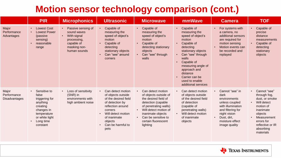
Motion sensor technology comparison (cont.) PIR Microphonics Ultrasonic Microwave mmWave Camera TOF
Major
Performance
Advantages
• Lowest Cost
• Lowest Power
(passive
sensing)
• reasonable
range
• Passive sensing of
sound waves
• With signal
processing,
capable of
masking non-
human sounds
• Capable of
measuring the
speed of object’s
motion
• Capable of
detecting
stationary objects
• Can “see” around
corners
• Capable of
measuring the
speed of object’s
motion
• Capable of
detecting stationary
objects
• Can “see” through
walls
• Capable of
measuring the
speed of object’s
motion
• Capable of
detecting
stationary objects
• Can “see” through
walls
• Capable of
measuring angle of
approach and
distance
• Carrier can be
used to enable
additional services
• For systems with
a camera, no
additional sensors
are required for
motion sensing
• Motion events can
be recorded and
replayed
• Capable of
precise
distance
measurements
• Capable of
detecting
stationary
objects
Major
Performance
Disadvantages
• Sensitive to
false
triggering for
anything
creating
changes in
temperature
or white light
• Long time
constant
• Loss of sensitivity
(SNR) in
environments with
high ambient noise
• Can detect motion
of objects outside
of the desired field
of detection by
reflection around
corners
• Will detect motion
of inanimate
objects
• Can be harmful to
pets
• Can detect motion
of objects outside of
the desired field of
detection (capable
of penetrating walls)
• Will detect motion of
inanimate objects
• Can be sensitive to
certain fluorescent
lighting
• Can detect motion
of objects outside
of the desired field
of detection
(capable of
penetrating walls)
• Will detect motion
of inanimate
objects
• Cannot “see” in
dark
environments
unless coupled
with illumination
and filtering for
night vision
• Dust, dirt,
moisture effect
image quality
• Cannot “see”
through fog,
dust, or smoke
• Will detect
motion of
inanimate
objects
• Measurement
errors for
reflective or IR
absorbing
materials
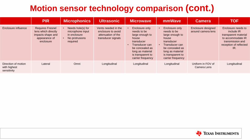
Motion sensor technology comparison (cont.)
PIR Microphonics Ultrasonic Microwave mmWave Camera TOF
Enclosure influence Requires Fresnel
lens which directly
impacts shape and
appearance of
enclosure
• Needs hole(s) for
microphone input
in enclosure
• No protrusions
required
Vents needed in the
enclosure to avoid
attenuation of the
transducer signals
• Enclosure only
needs to be
large enough to
house
transducer
• Transducer can
be concealed as
long as material
is transparent to
carrier frequency
• Enclosure only
needs to be
large enough to
house
transducer
• Transducer can
be concealed as
long as material
is transparent to
carrier frequency
Enclosure designed
around camera lens
Enclosure needs to
include IR
transparent material
to accommodate IR
transmission and
reception of reflected
IR.
Direction of motion
with highest
sensitivity
Lateral Omni Longitudinal Longitudinal Longitudinal Uniform in FOV of
Camera Lens
Longitudinal

SLYP722

IMPORTANT NOTICE AND DISCLAIMER
TI PROVIDES TECHNICAL AND RELIABILITY DATA (INCLUDING DATASHEETS), DESIGN RESOURCES (INCLUDING REFERENCE DESIGNS), APPLICATION OR OTHER DESIGN ADVICE, WEB TOOLS, SAFETY INFORMATION, AND OTHER RESOURCES “AS IS” AND WITH ALL FAULTS, AND DISCLAIMS ALL WARRANTIES, EXPRESS AND IMPLIED, INCLUDING WITHOUT LIMITATION ANY IMPLIED WARRANTIES OF MERCHANTABILITY, FITNESS FOR A PARTICULAR PURPOSE OR NON-INFRINGEMENT OF THIRD PARTY INTELLECTUAL PROPERTY RIGHTS.These resources are intended for skilled developers designing with TI products. You are solely responsible for (1) selecting the appropriate TI products for your application, (2) designing, validating and testing your application, and (3) ensuring your application meets applicable standards, and any other safety, security, or other requirements. These resources are subject to change without notice. TI grants you permission to use these resources only for development of an application that uses the TI products described in the resource. Other reproduction and display of these resources is prohibited. No license is granted to any other TI intellectual property right or to any third party intellectual property right. TI disclaims responsibility for, and you will fully indemnify TI and its representatives against, any claims, damages, costs, losses, and liabilities arising out of your use of these resources.TI’s products are provided subject to TI’s Terms of Sale (www.ti.com/legal/termsofsale.html) or other applicable terms available either on ti.com or provided in conjunction with such TI products. TI’s provision of these resources does not expand or otherwise alter TI’s applicable warranties or warranty disclaimers for TI products.
Mailing Address: Texas Instruments, Post Office Box 655303, Dallas, Texas 75265Copyright © 2020, Texas Instruments Incorporated