TECHNICAL DATA - daikintech.co.uk · design, development, ... Sound level data Sound pressure...
17
TECHNICAL DATA Split-Sky Air FDYP-B7 Concealed Ceiling Unit
Transcript of TECHNICAL DATA - daikintech.co.uk · design, development, ... Sound level data Sound pressure...
TECHNICAL DATA
Split-Sky Air
FDYP-B7
Concealed Ceiling Unit
Split Sky Air
Zandvoordestraat 300, B-8400 Oostende
Internet http://www.daikin.be
Daikin units comply with the European regulations that guarantee the safety of the product.
Daikin Europe NV is participating in the EUROVENT Certification Programme.Products are as listed in the EUROVENT Directory of Certified Products.
Prepared in Belgium by Goekint Graphics • 05/2001
ISO14001 assures an effective environmental management system in order to help protecthuman health and the environment from the potentialimpact of our activities, products and services and toassist in maintaining and improving the quality ofthe environment
Daikin Europe NV is approved by LRQA for its Quality Management System in accordance with the ISO9001 standard. ISO9001 pertains to quality assurance regarding design, development, manufacturing as well as to services related to the product.
DAIKIN PRODUCTS ARE DISTRIBUTED BY :
Specifications are subject to change without prior notice
TABLE OF CONTENTSFDYP-B7
1 Features ...................................................................................................... 2
2 Specifications ........................................................................................ 3
Nominal capacity, capacity steps and nominal input
Technical specifications
Electrical specifications
3 Dimensional drawings ................................................................. 7
4 Piping diagrams ................................................................................. 8
5 Wiring diagrams ................................................................................ 9
6 Sound level ............................................................................................. 10
Sound level data
Sound pressure spectrum
7 Fan characteristics ........................................................................... 11
8 Accessories .............................................................................................. 12
Standard accessories
Optional accessories
9 Control systems ................................................................................. 13
10 Installation ............................................................................................... 15
For capacity tables, please refer to the outdoor units concerned
• Concealed Ceiling Unit • R-407C • FDYP125-250B7V1
1• Split - Sky Air • Indoor Units
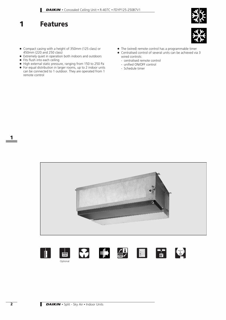
1 Features
+ Compact casing with a height of 350mm (125 class) or450mm (220 and 250 class)
+ Extremely quiet in operation both indoors and outdoors+ Fits flush into each ceiling+ High external static pressure, ranging from 150 to 250 Pa+ For equal distribution in larger rooms, up to 2 indoor units
can be connected to 1 outdoor. They are operated from 1remote control
+ The (wired) remote control has a programmable timer+ Centralised control of several units can be achieved via 3
wired controls:- centralised remote control- unified ON/OFF control- Schedule timer
1 3 x 3 6 ) 6Optional
• Concealed Ceiling Unit • R-407C • FDYP125-250B7V1
81
2 • Split - Sky Air • Indoor Units
2 Specifications
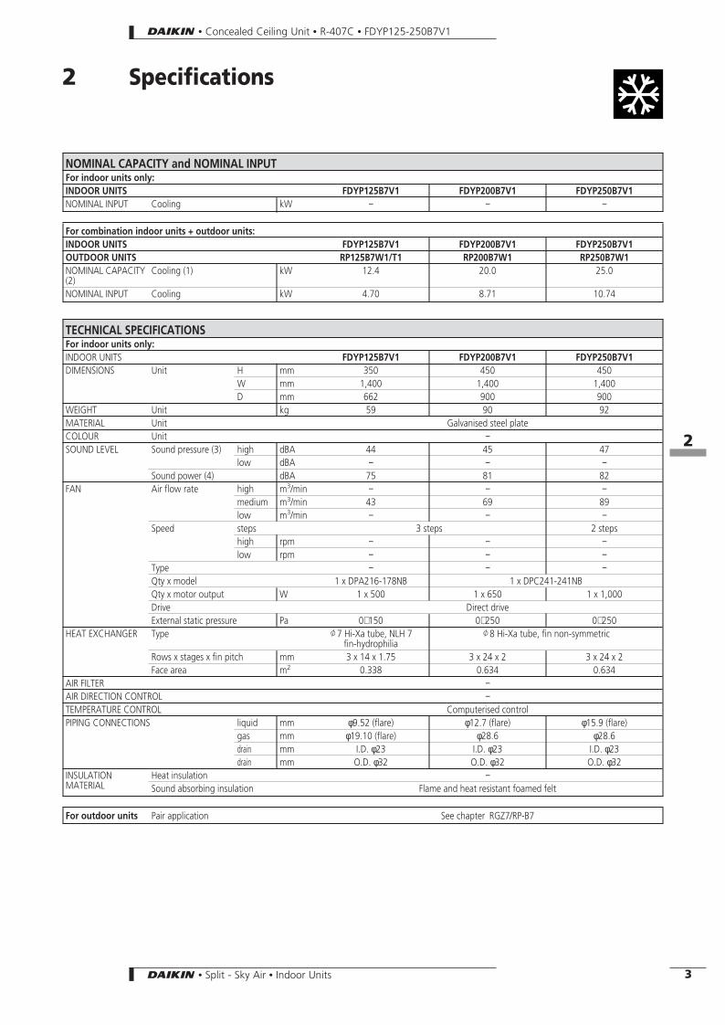
NOMINAL CAPACITY and NOMINAL INPUTFor indoor units only:INDOOR UNITS FDYP125B7V1 FDYP200B7V1 FDYP250B7V1NOMINAL INPUT Cooling kW − − −
For combination indoor units + outdoor units:INDOOR UNITS FDYP125B7V1 FDYP200B7V1 FDYP250B7V1OUTDOOR UNITS RP125B7W1/T1 RP200B7W1 RP250B7W1NOMINAL CAPACITY(2)
Cooling (1) kW 12.4 20.0 25.0
NOMINAL INPUT Cooling kW 4.70 8.71 10.74
TECHNICAL SPECIFICATIONSFor indoor units only:INDOOR UNITS FDYP125B7V1 FDYP200B7V1 FDYP250B7V1DIMENSIONS Unit H mm 350 450 450
W mm 1,400 1,400 1,400D mm 662 900 900
WEIGHT Unit kg 59 90 92MATERIAL Unit Galvanised steel plateCOLOUR Unit −SOUND LEVEL Sound pressure (3) high dBA 44 45 47
low dBA − − −Sound power (4) dBA 75 81 82
FAN Air flow rate high m3/min − − −medium m3/min 43 69 89low m3/min − − −
Speed steps 3 steps 2 stepshigh rpm − − −low rpm − − −
Type − − −Qty x model 1 x DPA216-178NB 1 x DPC241-241NBQty x motor output W 1 x 500 1 x 650 1 x 1,000Drive Direct driveExternal static pressure Pa 0∼150 0∼250 0∼250
HEAT EXCHANGER Type J7 Hi-Xa tube, NLH 7fin-hydrophilia
J8 Hi-Xa tube, fin non-symmetric
Rows x stages x fin pitch mm 3 x 14 x 1.75 3 x 24 x 2 3 x 24 x 2Face area m2 0.338 0.634 0.634
AIR FILTER −AIR DIRECTION CONTROL −TEMPERATURE CONTROL Computerised controlPIPING CONNECTIONS liquid mm φ9.52 (flare) φ12.7 (flare) φ15.9 (flare)
gas mm φ19.10 (flare) φ28.6 φ28.6drain mm I.D. φ23 I.D. φ23 I.D. φ23drain mm O.D. φ32 O.D. φ32 O.D. φ32
INSULATIONMATERIAL
Heat insulation −Sound absorbing insulation Flame and heat resistant foamed felt
For outdoor units Pair application See chapter RGZ7/RP-B7
• Concealed Ceiling Unit • R-407C • FDYP125-250B7V1
82
3• Split - Sky Air • Indoor Units
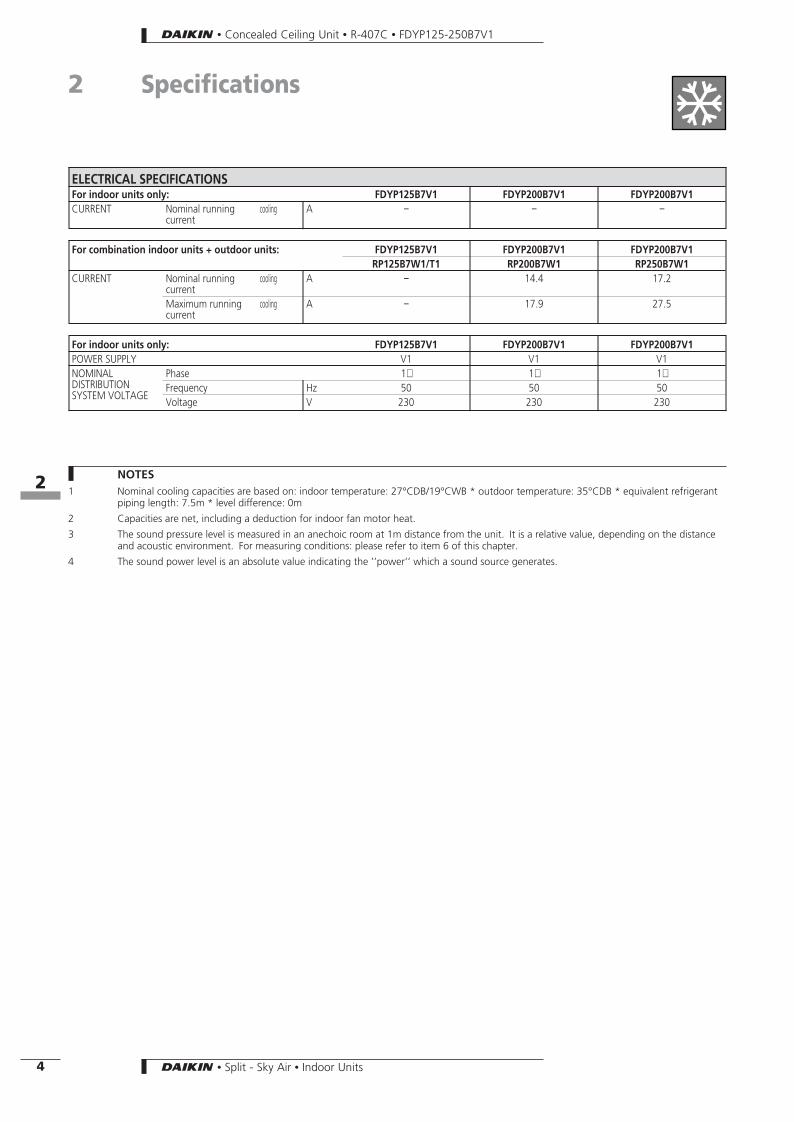
ELECTRICAL SPECIFICATIONSFor indoor units only: FDYP125B7V1 FDYP200B7V1 FDYP200B7V1CURRENT Nominal running
currentcooling A − − −
For combination indoor units + outdoor units: FDYP125B7V1 FDYP200B7V1 FDYP200B7V1RP125B7W1/T1 RP200B7W1 RP250B7W1
CURRENT Nominal runningcurrent
cooling A − 14.4 17.2
Maximum runningcurrent
cooling A − 17.9 27.5
For indoor units only: FDYP125B7V1 FDYP200B7V1 FDYP200B7V1POWER SUPPLY V1 V1 V1NOMINALDISTRIBUTIONSYSTEM VOLTAGE
Phase 1∼ 1∼ 1∼Frequency Hz 50 50 50Voltage V 230 230 230
NOTES1 Nominal cooling capacities are based on: indoor temperature: 27°CDB/19°CWB * outdoor temperature: 35°CDB * equivalent refrigerant
piping length: 7.5m * level difference: 0m
2 Capacities are net, including a deduction for indoor fan motor heat.
3 The sound pressure level is measured in an anechoic room at 1m distance from the unit. It is a relative value, depending on the distanceand acoustic environment. For measuring conditions: please refer to item 6 of this chapter.
4 The sound power level is an absolute value indicating the ’’power’’ which a sound source generates.
• Concealed Ceiling Unit • R-407C • FDYP125-250B7V1
2 Specifications
82
4 • Split - Sky Air • Indoor Units
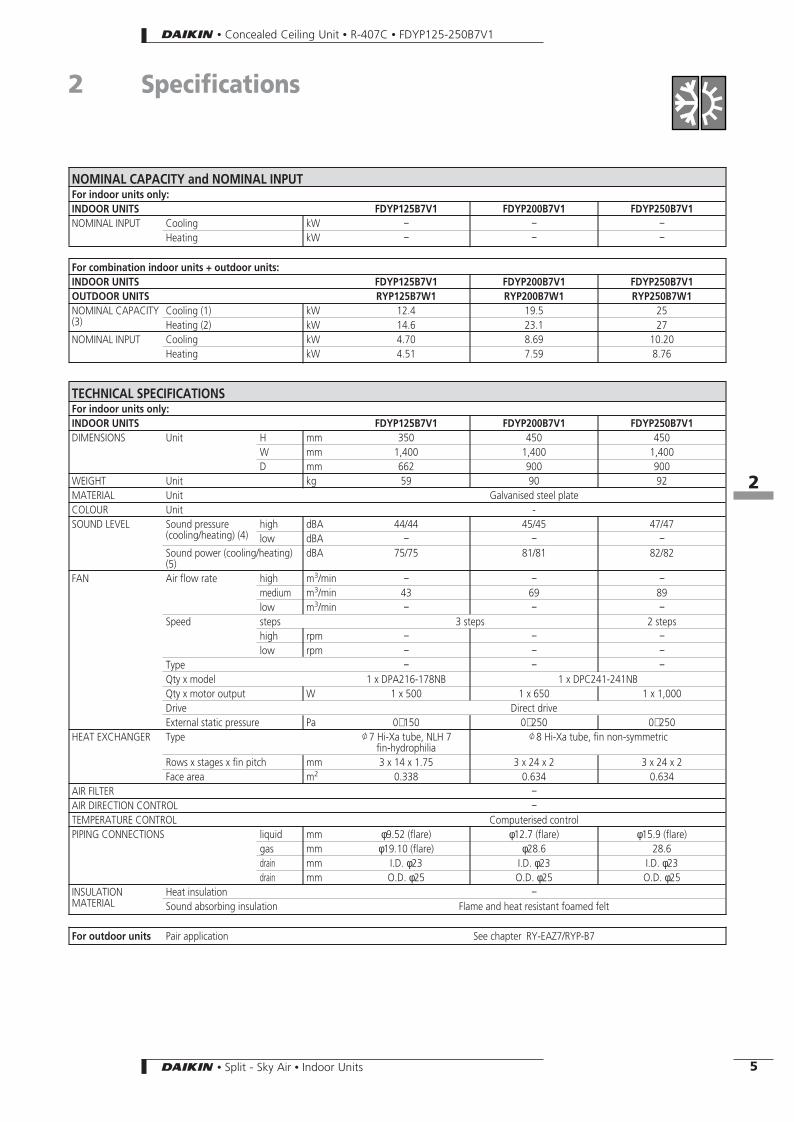
NOMINAL CAPACITY and NOMINAL INPUTFor indoor units only:INDOOR UNITS FDYP125B7V1 FDYP200B7V1 FDYP250B7V1NOMINAL INPUT Cooling kW − − −
Heating kW − − −
For combination indoor units + outdoor units:INDOOR UNITS FDYP125B7V1 FDYP200B7V1 FDYP250B7V1OUTDOOR UNITS RYP125B7W1 RYP200B7W1 RYP250B7W1NOMINAL CAPACITY(3)
Cooling (1) kW 12.4 19.5 25Heating (2) kW 14.6 23.1 27
NOMINAL INPUT Cooling kW 4.70 8.69 10.20Heating kW 4.51 7.59 8.76
TECHNICAL SPECIFICATIONSFor indoor units only:INDOOR UNITS FDYP125B7V1 FDYP200B7V1 FDYP250B7V1DIMENSIONS Unit H mm 350 450 450
W mm 1,400 1,400 1,400D mm 662 900 900
WEIGHT Unit kg 59 90 92MATERIAL Unit Galvanised steel plateCOLOUR Unit -SOUND LEVEL Sound pressure
(cooling/heating) (4)high dBA 44/44 45/45 47/47low dBA − − −
Sound power (cooling/heating)(5)
dBA 75/75 81/81 82/82
FAN Air flow rate high m3/min − − −medium m3/min 43 69 89low m3/min − − −
Speed steps 3 steps 2 stepshigh rpm − − −low rpm − − −
Type − − −Qty x model 1 x DPA216-178NB 1 x DPC241-241NBQty x motor output W 1 x 500 1 x 650 1 x 1,000Drive Direct driveExternal static pressure Pa 0∼150 0∼250 0∼250
HEAT EXCHANGER Type J7 Hi-Xa tube, NLH 7fin-hydrophilia
J8 Hi-Xa tube, fin non-symmetric
Rows x stages x fin pitch mm 3 x 14 x 1.75 3 x 24 x 2 3 x 24 x 2Face area m2 0.338 0.634 0.634
AIR FILTER −AIR DIRECTION CONTROL −TEMPERATURE CONTROL Computerised controlPIPING CONNECTIONS liquid mm φ9.52 (flare) φ12.7 (flare) φ15.9 (flare)
gas mm φ19.10 (flare) φ28.6 28.6drain mm I.D. φ23 I.D. φ23 I.D. φ23drain mm O.D. φ25 O.D. φ25 O.D. φ25
INSULATIONMATERIAL
Heat insulation −Sound absorbing insulation Flame and heat resistant foamed felt
For outdoor units Pair application See chapter RY-EAZ7/RYP-B7
• Concealed Ceiling Unit • R-407C • FDYP125-250B7V1
2 Specifications
82
5• Split - Sky Air • Indoor Units
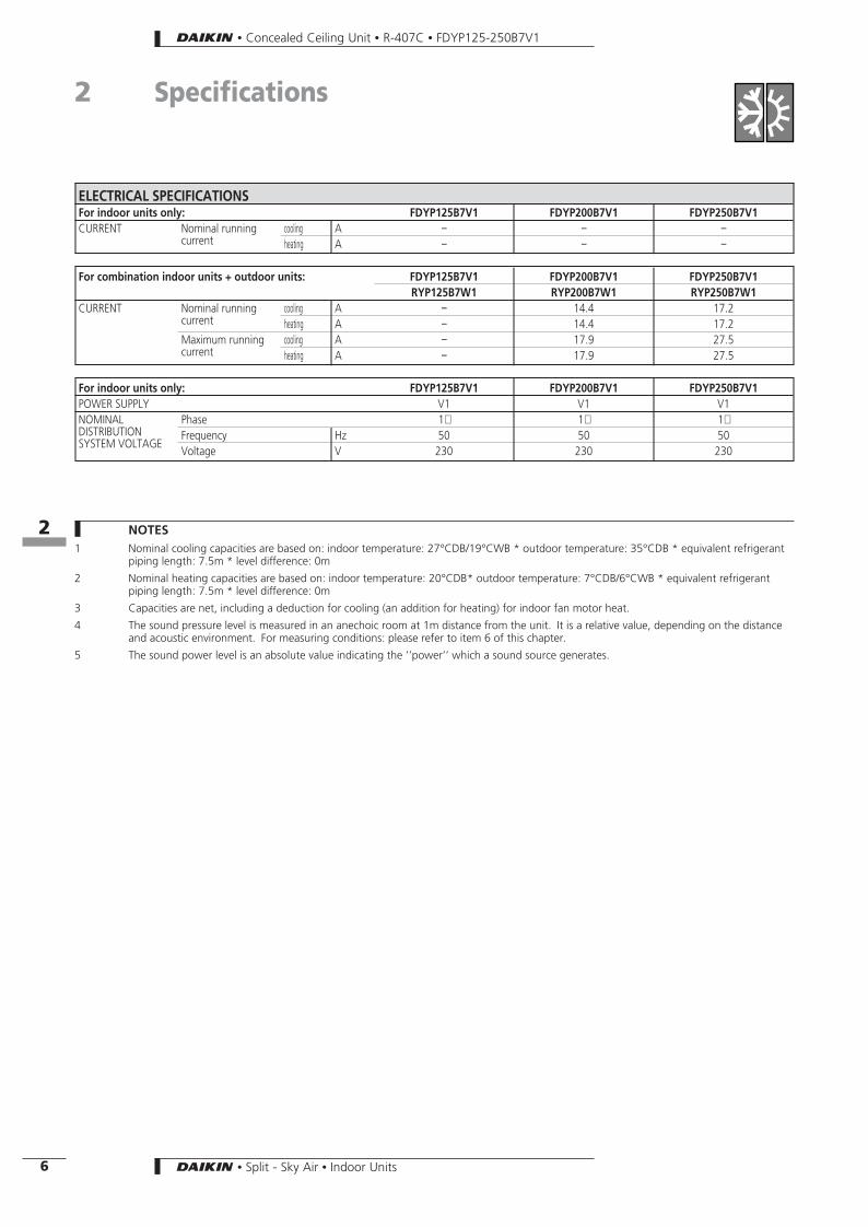
ELECTRICAL SPECIFICATIONSFor indoor units only: FDYP125B7V1 FDYP200B7V1 FDYP250B7V1CURRENT Nominal running
currentcooling A − − −heating A − − −
For combination indoor units + outdoor units: FDYP125B7V1 FDYP200B7V1 FDYP250B7V1RYP125B7W1 RYP200B7W1 RYP250B7W1
CURRENT Nominal runningcurrent
cooling A − 14.4 17.2heating A − 14.4 17.2
Maximum runningcurrent
cooling A − 17.9 27.5heating A − 17.9 27.5
For indoor units only: FDYP125B7V1 FDYP200B7V1 FDYP250B7V1POWER SUPPLY V1 V1 V1NOMINALDISTRIBUTIONSYSTEM VOLTAGE
Phase 1∼ 1∼ 1∼Frequency Hz 50 50 50Voltage V 230 230 230
NOTES1 Nominal cooling capacities are based on: indoor temperature: 27°CDB/19°CWB * outdoor temperature: 35°CDB * equivalent refrigerant
piping length: 7.5m * level difference: 0m
2 Nominal heating capacities are based on: indoor temperature: 20°CDB* outdoor temperature: 7°CDB/6°CWB * equivalent refrigerantpiping length: 7.5m * level difference: 0m
3 Capacities are net, including a deduction for cooling (an addition for heating) for indoor fan motor heat.
4 The sound pressure level is measured in an anechoic room at 1m distance from the unit. It is a relative value, depending on the distanceand acoustic environment. For measuring conditions: please refer to item 6 of this chapter.
5 The sound power level is an absolute value indicating the ’’power’’ which a sound source generates.
• Concealed Ceiling Unit • R-407C • FDYP125-250B7V1
2 Specifications
82
6 • Split - Sky Air • Indoor Units
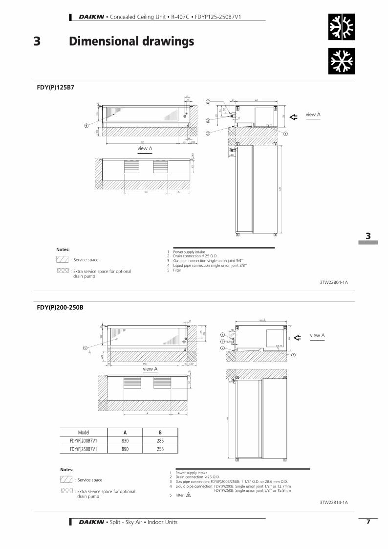
3 Dimensional drawings
FDY(P)125B7
view A
view A
Notes:
P : Service space
: Extra service space for optionaldrain pump
1 Power supply intake2 Drain connection J25 O.D.3 Gas pipe connection single union joint 3/4’’4 Liquid pipe connection single union joint 3/8’’5 Filter
3TW22804-1A
FDY(P)200-250B
view A
view A
Notes:
P : Service space
: Extra service space for optionaldrain pump
1 Power supply intake2 Drain connection J25 O.D.3 Gas pipe connection: FDY(P)200B/250B: 1 1/8″ O.D. or 28.6 mm O.D.4 Liquid pipe connection: FDY(P)200B: Single union joint 1/2’’ or 12.7mm
FDY(P)250B: Single union joint 5/8’’ or 15.9mm5 Filter _A
3TW22814-1A
Model A B
FDY(P)200B7V1 830 285
FDY(P)250B7V1 890 255
• Concealed Ceiling Unit • R-407C • FDYP125-250B7V1
83
7• Split - Sky Air • Indoor Units
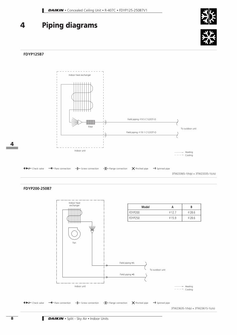
4 Piping diagrams
FDYP125B7
3TW23365-1(h/p) + 3TW23335-1(c/o)
Indoor unit
Field piping J19.1 C122OT-O
Field piping J9.5 C122OT-O
Indoor heat exchanger
Filter
O Check valve L Flare connection M Screw connection N Flange connection Z Pinched pipe P Spinned pipe
HeatingCooling
To outdoor unit
FDYP200-250B7
3TW23635-1(h/p) + 3TW23615-1(c/o)
Indoor unit
Field piping •B
Field piping •A
Indoor heatexchanger
O Check valve L Flare connection M Screw connection N Flange connection Z Pinched pipe P Spinned pipe
HeatingCooling
Fan
Model A B
FDYP200 J12.7 J28.6
FDYP250 J15.9 J28.6
To outdoor unit
• Concealed Ceiling Unit • R-407C • FDYP125-250B7V1
84
8 • Split - Sky Air • Indoor Units
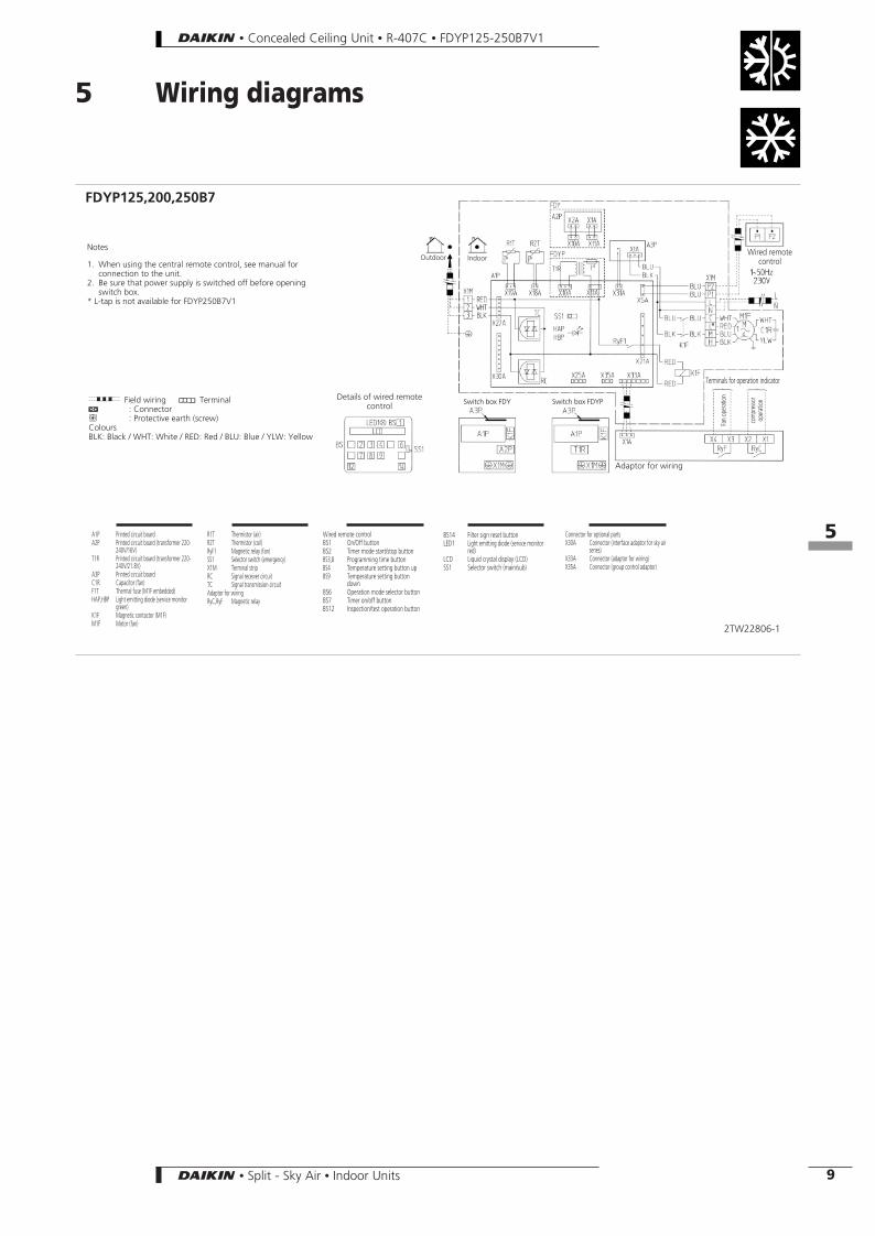
5 Wiring diagrams
2TW22806-1
FDYP125,200,250B7
A1P Printed circuit boardA2P Printed circuit board (transformer 220-
240V/16V)T1R Printed circuit board (transformer 220-
240V/21.8V)A3P Printed circuit boardC1R Capacitor (fan)F1T Thermal fuse (M1F embedded)HAP,HBP Light emitting diode (service monitor
green)K1F Magnetic contactor (M1F)M1F Motor (fan)
R1T Thermistor (air)R2T Thermistor (coil)RyF1 Magnetic relay (fan)SS1 Selector switch (emergency)X1M Terminal stripRC Signal receiver circuitTC Signal transmission circuitAdaptor for wiringRyC,RyF Magnetic relay
Wired remote controlBS1 On/Off buttonBS2 Timer mode start/stop buttonBS3,8 Programming time buttonBS4 Temperature setting button upBS9 Temperature setting button
downBS6 Operation mode selector buttonBS7 Timer on/off buttonBS12 Inspection/test operation button
Connector for optional partsX30A Connector (interface adaptor for sky air
series)X33A Connector (adaptor for wiring)X35A Connector (group control adaptor)
IndoorOutdoorWired remote
control
Terminals for operation indicator
Details of wired remotecontrol
Adaptor for wiring
Fan
oper
atio
n
com
pres
sor
oper
atio
n
Notes
1. When using the central remote control, see manual forconnection to the unit.
2. Be sure that power supply is switched off before openingswitch box.
* L-tap is not available for FDYP250B7V1
g Field wiring D TerminalF : Connectorb : Protective earth (screw)ColoursBLK: Black / WHT: White / RED: Red / BLU: Blue / YLW: Yellow
BS14 Filter sign reset buttonLED1 Light emitting diode (service monitor
red)LCD Liquid crystal display (LCD)SS1 Selector switch (main/sub)
Switch box FDY Switch box FDYP
• Concealed Ceiling Unit • R-407C • FDYP125-250B7V1
85
9• Split - Sky Air • Indoor Units
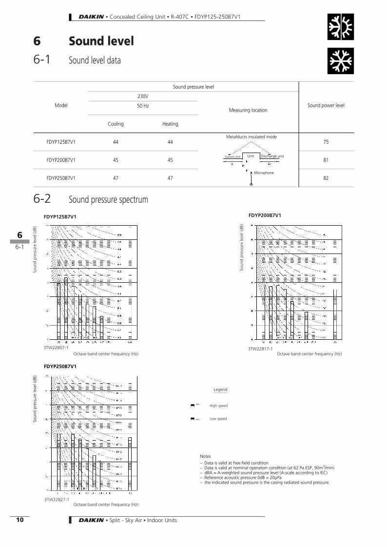
6 Sound level6-1 Sound level data
Soun
dpr
essu
rele
vel(
dB)
Soun
dpr
essu
rele
vel(
dB)
Octave band center frequency (Hz) Octave band center frequency (Hz)
Octave band center frequency (Hz)
FDYP125B7V1 FDYP200B7V1
3TW22817-13TW22807-1
3TW22827-1
Legend
High speed
Low speed
6-2 Sound pressure spectrum
Soun
dpr
essu
rele
vel(
dB)
FDYP250B7V1
Notes
– Data is valid at free field condition– Data is valid at nominal operation condition (at 62 Pa ESP, 90m3/min)– dBA = A-weighted sound pressure level (A-scale according to IEC)– Reference acoustic pressure 0dB = 20µPa– the indicated sound pressure is the casing radiated sound pressure.
Model
Sound pressure level
Sound power level
230V
Measuring location50 Hz
Cooling Heating
FDYP125B7V1 44 44 75
FDYP200B7V1 45 45 81
FDYP250B7V1 47 47 82
Suction unit Unit Discharge unit
Microphone
Metalducts insulated inside
• Concealed Ceiling Unit • R-407C • FDYP125-250B7V1
86
6-1
10 • Split - Sky Air • Indoor Units

7 Fan characteristics
3TW22808-1
FDYP125B7V1
FDYP200B7V1
3TW22818-1
FDYP250B7V1
3TW22828-1
highmedium
low
high
medium
low
high
medium
• Concealed Ceiling Unit • R-407C • FDYP125-250B7V1
87
11• Split - Sky Air • Indoor Units
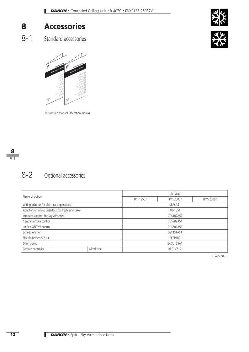
8 Accessories8-1 Standard accessories
Name of optionKit name
FDYP125B7 FDYP200B7 FDYP250B7
Wiring adaptor for electrical appendices KRP4A51
Adaptor for wiring (interlock for fresh air intake) KRP1B54
Interface adaptor for Sky Air series DTA102A52
Central remote control DCS302A51
unified ON/OFF control DCS301A51
Schedule timer DST301A51
Electric heater PCB kit EKRP1B2
Drain pump EKDU125A1
Remote controller Wired type BRC1C517
3TW22809-1
8-2 Optional accessories
Installation manual Operation manual
• Concealed Ceiling Unit • R-407C • FDYP125-250B7V1
88
8-1
12 • Split - Sky Air • Indoor Units
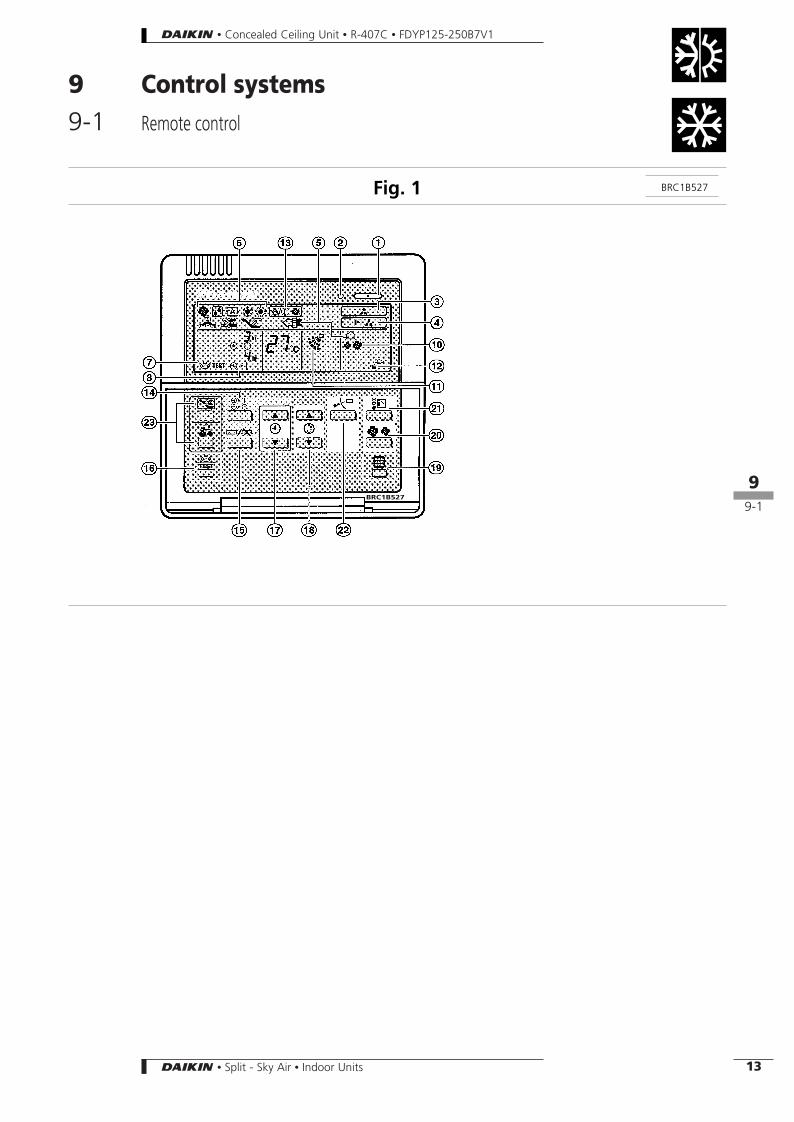
9 Control systems9-1 Remote control
BRC1B527Fig. 1
BRC1B527
• Concealed Ceiling Unit • R-407C • FDYP125-250B7V1
89
9-1
13• Split - Sky Air • Indoor Units
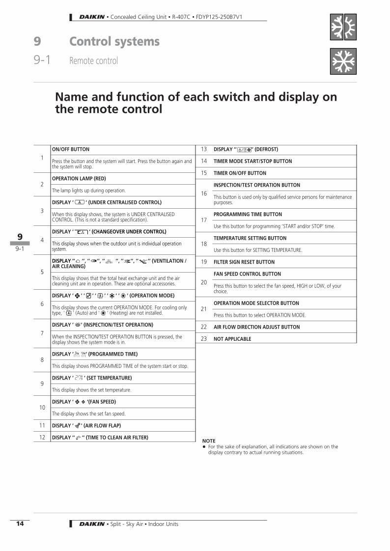
Name and function of each switch and display onthe remote control
1ON/OFF BUTTON
Press the button and the system will start. Press the button again andthe system will stop.
2OPERATION LAMP (RED)
The lamp lights up during operation.
3DISPLAY ’h ’ (UNDER CENTRALISED CONTROL)
When this display shows, the system is UNDER CENTRALISEDCONTROL. (This is not a standard specification).
4DISPLAY ’ ’ (CHANGEOVER UNDER CONTROL)
This display shows when the outdoor unit is individual operationsystem.
5
DISPLAY ’’ ’’, ’’ ’’, ’’ ’’, ’’ ’’, ’’ ’’ (VENTILATION /AIR CLEANING)
This display shows that the total heat exchange unit and the aircleaning unit are in operation. These are optional accessories.
6DISPLAY ’A ’ ’I ’ ’, ’ ’u ’ ’w ’ (OPERATION MODE)
This display shows the current OPERATION MODE. For cooling onlytype, ’, ’ (Auto) and ’w ’ (Heating) are not installed.
7DISPLAY ’b ’ (INSPECTION/TEST OPERATION)
When the INSPECTION/TEST OPERATION BUTTON is pressed, thedisplay shows the system mode is in.
8DISPLAY ’I’ (PROGRAMMED TIME)
This display shows PROGRAMMED TIME of the system start or stop.
9DISPLAY ’O ’ (SET TEMPERATURE)
This display shows the set temperature.
10DISPLAY ’BC ’(FAN SPEED)
The display shows the set fan speed.
11 DISPLAY ’a ’ (AIR FLOW FLAP)
12 DISPLAY ’’ ’’ (TIME TO CLEAN AIR FILTER)
13 DISPLAY ’’ ’’ (DEFROST)
14 TIMER MODE START/STOP BUTTON
15 TIMER ON/OFF BUTTON
16INSPECTION/TEST OPERATION BUTTON
This button is used only by qualified service persons for maintenancepurposes.
17PROGRAMMING TIME BUTTON
Use this button for programming ’START and/or STOP’ time.
18TEMPERATURE SETTING BUTTON
Use this button for SETTING TEMPERATURE.
19 FILTER SIGN RESET BUTTON
20FAN SPEED CONTROL BUTTON
Press this button to select the fan speed, HIGH or LOW, of yourchoice.
21OPERATION MODE SELECTOR BUTTON
Press this button to select OPERATION MODE.
22 AIR FLOW DIRECTION ADJUST BUTTON
23 NOT APPLICABLE
NOTE+ For the sake of explanation, all indications are shown on the
display contrary to actual running situations.
• Concealed Ceiling Unit • R-407C • FDYP125-250B7V1
9 Control systems9-1 Remote control
89
9-1
14 • Split - Sky Air • Indoor Units
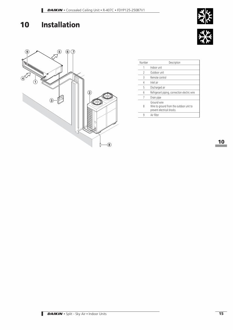
10 Installation
Number Description
1 Indoor unit
2 Outdoor unit
3 Remote control
4 Inlet air
5 Discharged air
6 Refrigerant piping, connection electric wire
7 Drain pipe
8Ground wireWire to ground from the outdoor unit toprevent electrical shocks.
9 Air filter
• Concealed Ceiling Unit • R-407C • FDYP125-250B7V1
810
15• Split - Sky Air • Indoor Units

![MISPRONUNCIATION OF ENGLISH CONSONANT SOUND [θ]](https://static.fdocument.org/doc/165x107/616f69e73344f852396ef8fd/mispronunciation-of-english-consonant-sound-.jpg)