TCC11 Element Design.xls of Slab and Beam
13
SOLID SLABS v 3.5 on CD © 2003-2005 TCC INPUT Location 1st Floor, Span H-J M kNm/m 15.12 fck N/mm² 32 γc = 1.50 δ 1.00 fyk N/mm² 500 γs = 1.15 span mm 5000 gk 7.50 h mm 250 qk 2.50 Bar Ø mm 8 Steel class A mm 35 to this steel Usage Office mm 10 Section location END SPAN brittle partitions? YES OUTPUT 1st Floor, Span H-J . d = 250 - 35 - 8/2 = 211.0 mm 3.1.7 (3) x = [211 - √(211² - 4000/0.85 x 15.12 x 1.5/32)]/0.8 5.5 (4) (x/d) limit = 0.600 x/d actual = 0.024 < 0.600 ok Fig 3.5 z = 211 - 0.4 x 5.0 = 209.0 > 0.95d . As = 15.12E6/500/200.5 x 1.15 = 173 < As min = 208 m 9.2.1.1 (1) As min = 1.57 x 211 = 208 mm²/m As def = 173 mm²/m Provide H8 @ 225 = 223 mm²/m Table A1.1 EN1990 0.3 (Office) QP udl = 7.5 + 0.3 x 2.5 = 8.25 kN/m², n = 7.5 x 1. QP M = 15.12 x 8.25/13.88 = 8 201.7 N/mm² 7.4.2 (2) Modification factor = 310/201.7 = 1.500(max) Table 7.4 Permissible L/d = 1.500 x 425.72 = 638.58 Actual L/d = 5000/211 = 23.70 ok . Section design to Eurocode 2 (BS EN 1992-1) Originated from TCC11.xls, kN/m 2 kN/m 2 cover, Cnom Δcdev ψ2 = ss =
-
Upload
amadu-farrow -
Category
Documents
-
view
156 -
download
41
Transcript of TCC11 Element Design.xls of Slab and Beam
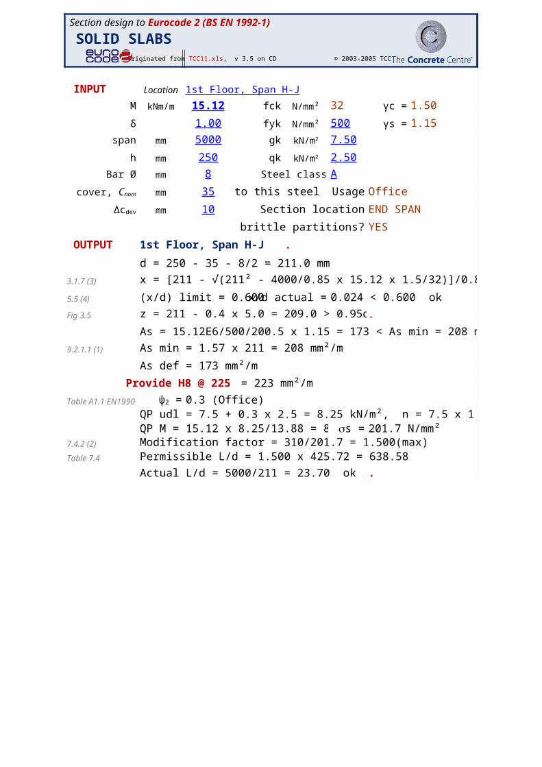
SOLID SLABSv 3.5 on CD © 2003-2005 TCC
INPUT Location 1st Floor, Span H-J
M kNm/m 15.12 fck N/mm² 32 γc = 1.50
δ 1.00 fyk N/mm² 500 γs = 1.15
span mm 5000 gk 7.50
h mm 250 qk 2.50
Bar Ø mm 8 Steel class A
mm 35 to this steel Usage Office
mm 10 Section location END SPAN
brittle partitions? YES
OUTPUT 1st Floor, Span H-J .
d = 250 - 35 - 8/2 = 211.0 mm
3.1.7 (3) x = [211 - √(211² - 4000/0.85 x 15.12 x 1.5/32)]/0.8 = 5.0 mm
5.5 (4) (x/d) limit = 0.600 x/d actual = 0.024 < 0.600 ok
Fig 3.5 z = 211 - 0.4 x 5.0 = 209.0 > 0.95d = 200. .
As = 15.12E6/500/200.5 x 1.15 = 173 < As min = 208 mm²/m
9.2.1.1 (1) As min = 1.57 x 211 = 208 mm²/m
As def = 173 mm²/m
Provide H8 @ 225 = 223 mm²/m
Table A1.1 EN199 0.3 (Office)QP udl = 7.5 + 0.3 x 2.5 = 8.25 kN/m², n = 7.5 x 1.35 + 2.5 x 1.5 = 13.88QP M = 15.12 x 8.25/13.88 = 8.99 k 201.7 N/mm²
7.4.2 (2) Modification factor = 310/201.7 = 1.500(max)Table 7.4 Permissible L/d = 1.500 x 425.72 = 638.58
Actual L/d = 5000/211 = 23.70 ok .
Section design to Eurocode 2 (BS EN 1992-1)
Originated from TCC11.xls,
kN/m2
kN/m2
cover, Cnom
Δcdev
ψ2 =
ss =
B8
Redistribution
B13
Cover Design Tolerance. Used for checking only.
Section design to Eurocode 2 (BS EN 1992-1)
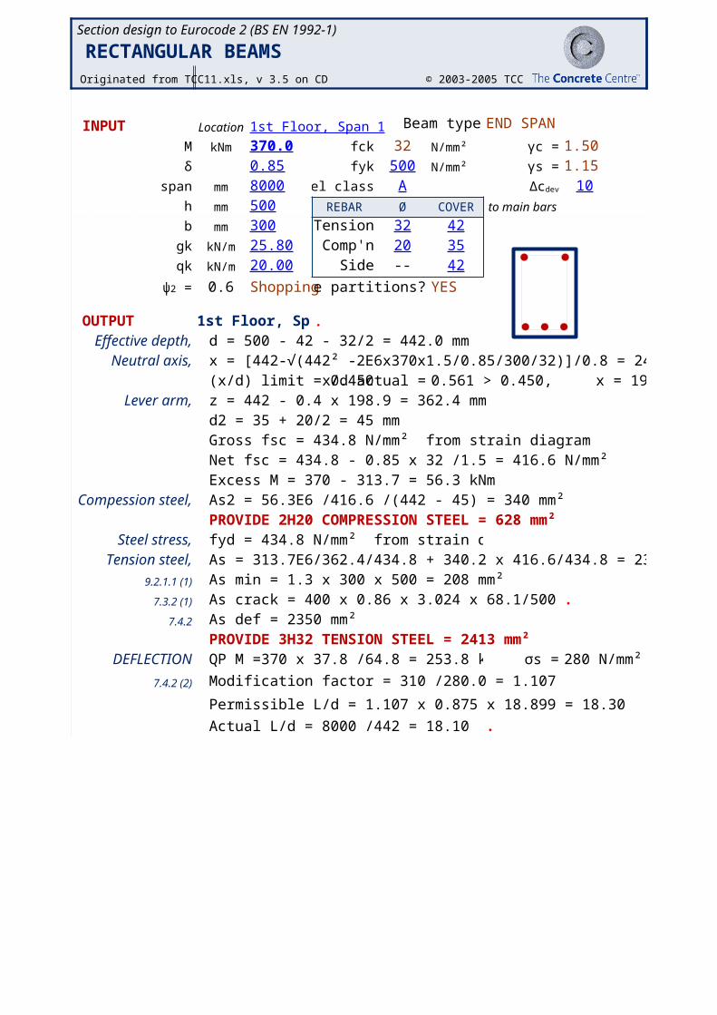
RECTANGULAR BEAMS Originated from TCC11.xls, v 3.5 on CD © 2003-2005 TCC
INPUT Location 1st Floor, Span 1 Beam type END SPAN
M kNm 370.0 fck 32 N/mm² γc = 1.50δ 0.85 fyk 500 N/mm² γs = 1.15
span mm 8000 teel class A 10h mm 500 REBAR Ø COVER to main bars
b mm 300 Tension 32 42gk kN/m 25.80 Comp'n 20 35qk kN/m 20.00 Side -- 42
0.6 Shoppingbrittle partitions? YES
OUTPUT 1st Floor, Span.
Effective depth, d = 500 - 42 - 32/2 = 442.0 mmNeutral axis, x = [442-√(442² -2E6x370x1.5/0.85/300/32)]/0.8 = 248.0 mm
(x/d) limit = 0.450 x/d actual = 0.561 > 0.450, x = 198.9 mmLever arm, z = 442 - 0.4 x 198.9 = 362.4 mm
d2 = 35 + 20/2 = 45 mmGross fsc = 434.8 N/mm² from strain diagramNet fsc = 434.8 - 0.85 x 32 /1.5 = 416.6 N/mm²Excess M = 370 - 313.7 = 56.3 kNm
Compession steel, As2 = 56.3E6 /416.6 /(442 - 45) = 340 mm²PROVIDE 2H20 COMPRESSION STEEL = 628 mm²
Steel stress, fyd = 434.8 N/mm² from strain diagram r = 280 N/mm²Tension steel, As = 313.7E6/362.4/434.8 + 340.2 x 416.6/434.8 = 2317 mm²
9.2.1.1 (1) As min = 1.3 x 300 x 500 = 208 mm²7.3.2 (1) As crack = 400 x 0.86 x 3.024 x 68.1/500 = 142 mm.
7.4.2 As def = 2350 mm²PROVIDE 3H32 TENSION STEEL = 2413 mm²
DEFLECTION QP M =370 x 37.8 /64.8 = 253.8 kNm σs = 280 N/mm²
7.4.2 (2) Modification factor = 310 /280.0 = 1.107
Permissible L/d = 1.107 x 0.875 x 18.899 = 18.30
Actual L/d = 8000 /442 = 18.10 ok .
Δcdev
ψ2 =
B8
Redistribution
H9
Cover Design Tolerance. Used for checking only.
G10
Cnom plus link diameter
Section design to Eurocode 2 (BS EN 1992-1)
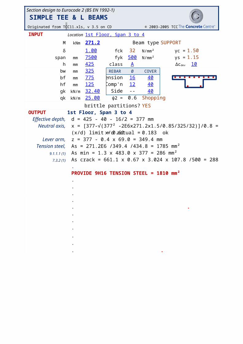
SIMPLE TEE & L BEAMS Originated from TCC11.xls, v 3.5 on CD © 2003-2005 TCC
INPUT Location 1st Floor, Span 3 to 4
M kNm 271.2 Beam type SUPPORT
δ 1.00 fck 32 N/mm² γc = 1.50span mm 7500 fyk 500 N/mm² γs = 1.15
h mm 425 el class A 10bw mm 325 REBAR Ø COVER
bf mm 775 Tension 16 40hf mm 125 Comp'n 12 40gk kN/m 32.40 Side -- 40qk kN/m 25.00 ψ2 = 0.6 Shopping
brittle partitions? YES OUTPUT 1st Floor, Span 3 to 4
Effective depth, d = 425 - 40 - 16/2 = 377 mmNeutral axis, x = [377-√(377² -2E6x271.2x1.5/0.85/325/32)]/0.8 = 69.0 mm
(x/d) limit = 0.600x/d actual = 0.183 okLever arm, z = 377 - 0.4 x 69.0 = 349.4 mm
Tension steel, As = 271.2E6 /349.4 /434.8 = 1785 mm²9.1.1.1 (1) As min = 1.3 x 483.0 x 377 = 286 mm²
7.3.2 (1) As crack = 661.1 x 0.67 x 3.024 x 107.8 /500 = 288 mm².PROVIDE 9H16 TENSION STEEL = 1810 mm².. σs = 274 N/mm²
7.4.2 (2) ... ...
. σs = 274 N/mm²
.
.
. .
Δcdev
B7
Redistribution
H9
Cover Design Tolerance. Used for checking only.
G10
Cnom plus link diameter
E14
Permanenr part of imposed load
Section design to Eurocode 2 (BS EN 1992-1)
Originated from TCC11.xls, v 3.5 on CD © 2003-2005 TCC
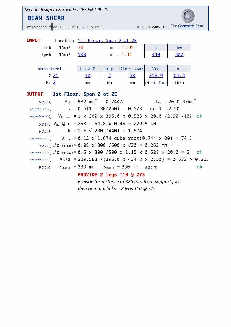
INPUT Location 1st Floor, Span 2 at 2E
fck N/mm² 30 γc = 1.50 d bw
fywk N/mm² 500 γs = 1.15 440 300
Main Steel Link Ø Legs Side cover n
Ø 25 10 2 30 258.0 64.8
No 2 mm No mm kN/m
OUTPUT 1st Floor, Span 2 at 2E
6.2.2 (1) 982 mm² = 0.744% 20.0 N/mm²
equation (6.6) 0.6(1 - 30/250) = 0.528 . 2.50
equation (6.9) 1 x 300 x 396.0 x 0.528 x 20.0 /2.90 /1000 = 432.6 ok
6.2.1 (8) 258 - 64.8 x 0.44 = 229.5 kN
6.2.2 (1) k = 1 + √(200 /440) = 1.674 .
equation (6.2) 0.12 x 1.674 cube root(0.744 x 30) = 74.7 kN .
9.2.2 (5) 0.08 x 300 /500 x √30 = 0.263 mm
equation (6.9) 0.5 x 300 /500 x 1.15 x 0.528 x 20.0 = 3.643 mm ok
equation (6.7) 229.5E3 /(396.0 x 434.8 x 2.50) = 0.533 > 0.263
9.2.2 (6) 330 mm 330 mm 9.2.2 (8) ok
PROVIDE 2 legs T10 @ 275
Provide for distance of 825 mm from support face
then nominal links = 2 legs T10 @ 325
BEAM SHEAR
VEd
kN at face
AsL = fcd =
n = cotθ =
VRd,max =
VEd @ d =
VRd,c =
Asw/s (min)=
Asw/s (max)=
Asw/s =
smax,L = smax,T =
F10
Cnom
Section design to Eurocode 2 (BS EN 1992-1)
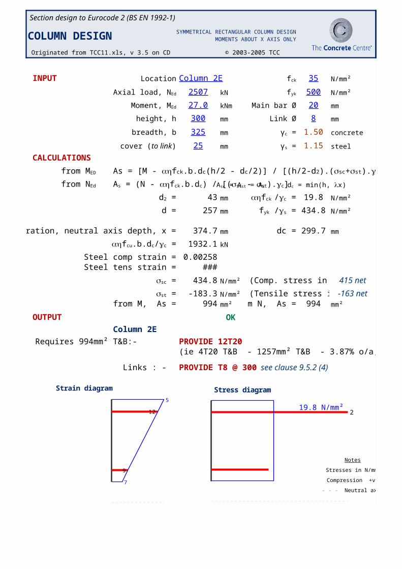
COLUMN DESIG Originated from TCC11.xls, v 3.5 on CD © 2003-2005 TCC
INPUT Location Column 2E 35 N/mm²
2507 kN 500 N/mm²
27.0 kNm Main bar Ø 20 mm
height, h 300 mm Link Ø 8 mm
breadth, b 325 mm 1.50 concrete
25 mm 1.15 steel
CALCULATIONS
43 mm 19.8 N/mm²
d = 257 mm 434.8 N/mm²
from iteration, neutral axis depth, x = 374.7 mm dc = 299.7 mm
1932.1 kN
Steel comp strain = 0.00258Steel tens strain = -0.00092
434.8 N/mm² (Comp. stress in reinf 415 net
-183.3 N/mm² (Tensile stress in rein -163 netfrom M, As = 994 mm² rom N, As = 994 mm²
OUTPUT OK
Column 2E
Requires 994mm² T&B:- PROVIDE 12T20(ie 4T20 T&B - 1257mm² T&B - 3.87% o/a, @80 c/c.)
Links : - PROVIDE T8 @ 300see clause 9.5.2 (4)
19.8 N/mm²
Notes
Compression +ve
SYMMETRICAL RECTANGULAR COLUMN DESIGNMOMENTS ABOUT X AXIS ONLY
fck
Axial load, NEd fyk
Moment, MEd
γc =
cover (to link) γs =
from MED As = [M - ahfck.b.dc(h/2 - dc/2)] / [(h/2-d2).(ssc+sst).gc]
from NEd As = (N - ahfck.b.dc) / [(ssc - sst).gc] Asc = Ast = As dc = min(h, lx)
d2 = ahfck /gc =
fyk /gs =
ahfcu.b.dc/gc =
ssc =
sst =
Stresses in N/mm2
- - - Neutral axis
2
Stress diagram5
7
9
12
Strain diagram
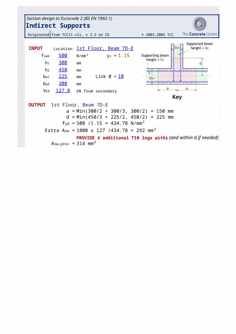
Section design to Eurocode 2 (BS EN 1992-1)
Indirect Supports Originated from TCC11.xls, v 3.5 on CD © 2003-2005 TCC
INPUT Location 1st Floor, Beam 7D-E
500 N/mm² 1.15
300 mm
450 mm
225 mm Link Ø = 10
300 mm
127.0 kN from secondary
OUTPUT 1st Floor, Beam 7D-Ea = Min(300/2 + 300/3, 300/2) = 150 mmd = Min(450/3 + 225/2, 450/2) = 225 mm
500 /1.15 = 434.78 N/mm²
1000 x 127 /434.78 = 292 mm²
PROVIDE 4 additional T10 legs within 2 (and within d,if needed)314 mm²
fywk γs =
h1
h2
bw1
bw2
VEd
fyd =
Extra Asw =
Asw,prov =
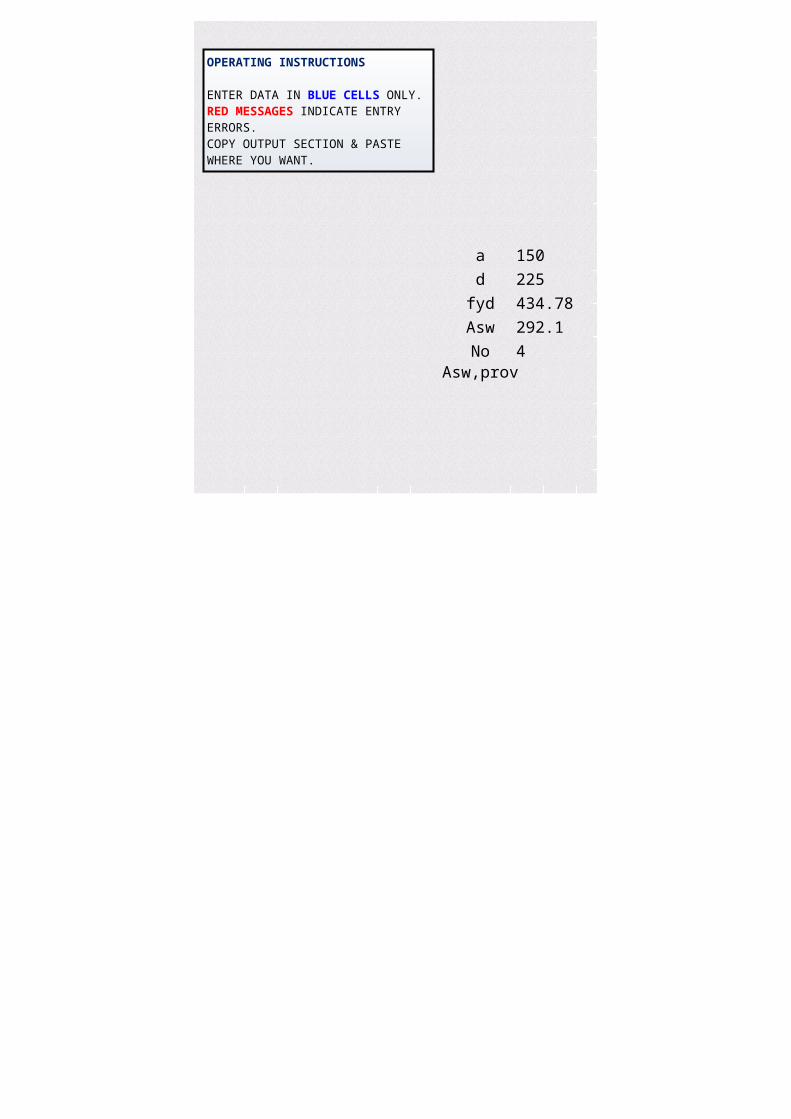
a 150
d 225
fyd 434.78
Asw 292.1
No 4Asw,prov
(and within d,if needed)
OPERATING INSTRUCTIONS
ENTER DATA IN BLUE CELLS ONLY.RED MESSAGES INDICATE ENTRY ERRORS.COPY OUTPUT SECTION & PASTE WHERE YOU WANT.
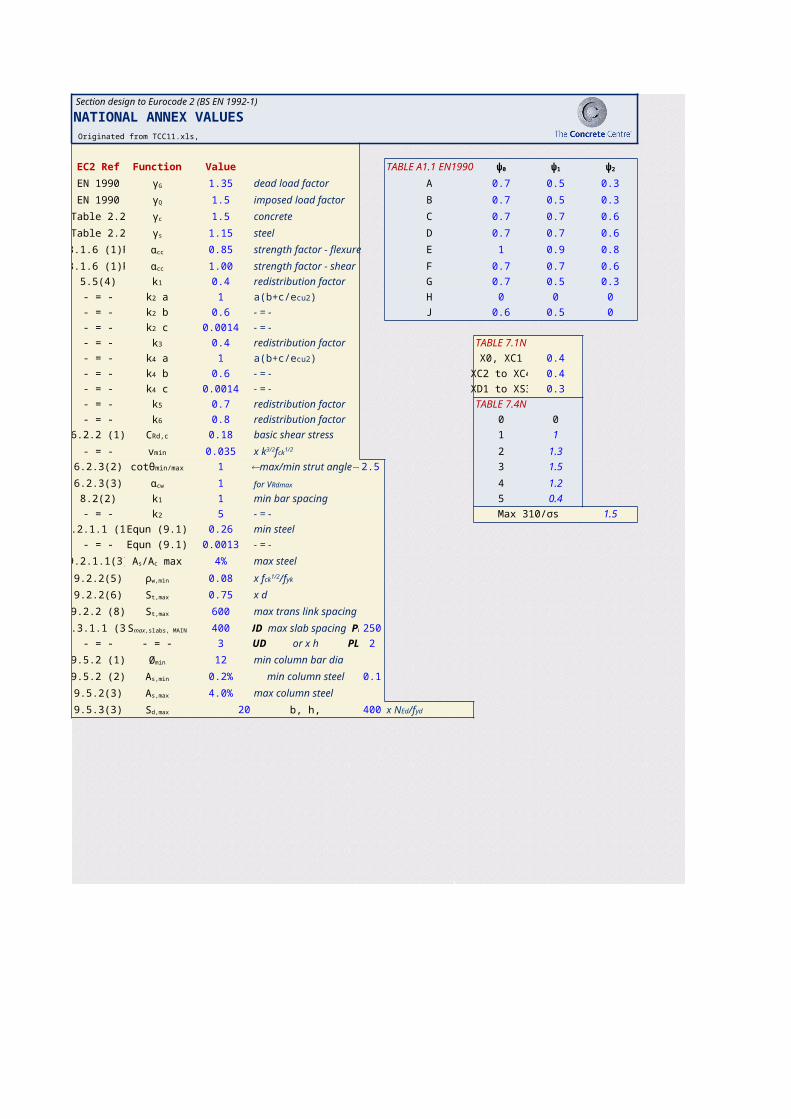
Section design to Eurocode 2 (BS EN 1992-1)
NATIONAL ANNEX VALUES Originated from TCC11.xls,
EC2 Ref Function Value TABLE A1.1 EN199
EN 1990 1.35 dead load factor A 0.7 0.5 0.3
EN 1990 1.5 imposed load factor B 0.7 0.5 0.3
Table 2.2 1.5 concrete C 0.7 0.7 0.6
Table 2.2 1.15 steel D 0.7 0.7 0.6
3.1.6 (1)P 0.85 strength factor - flexure E 1 0.9 0.8
3.1.6 (1)P 1.00 strength factor - shear F 0.7 0.7 0.6
5.5(4) 0.4 redistribution factor G 0.7 0.5 0.3
- = - 1 H 0 0 0
- = - 0.6 - = - J 0.6 0.5 0
- = - 0.0014 - = -
- = - 0.4 redistribution factor TABLE 7.1N
- = - 1 X0, XC1 0.4
- = - 0.6 - = - XC2 to XC4 0.4
- = - 0.0014 - = - XD1 to XS3 0.3
- = - 0.7 redistribution factor TABLE 7.4N
- = - 0.8 redistribution factor 0 0
6.2.2 (1) 0.18 basic shear stress 1 1
- = - 0.035 2 1.3
6.2.3(2) 1 2.5 3 1.5
6.2.3(3) 1 4 1.2
8.2(2) 1 min bar spacing 5 0.4
- = - 5 - = - Max 310/σs 1.5
9.2.1.1 (1) Equn (9.1) 0.26 min steel
- = - Equn (9.1) 0.0013 - = -
9.2.1.1(3) 4% max steel
9.2.2(5) 0.08
9.2.2(6) 0.75 x d
9.2.2 (8) 600 max trans link spacing
9.3.1.1 (3) 400 250
- = - - = - 3 2
9.5.2 (1) 12 min column bar dia
9.5.2 (2) 0.2% min column steel 0.1
9.5.2(3) 4.0% max column steel
9.5.3(3) 20 400
ψ0 ψ1 ψ2
γG
γQ
γc
γs
αcc
αcc
k1
k2 a a(b+c/ecu2)
k2 b
k2 c
k3
k4 a a(b+c/ecu2)
k4 b
k4 c
k5
k6
CRd,c
vmin x k3/2fck1/2
cotθmin/max ¬max/min strut angle®αcw for VRdmax
k1
k2
As/Ac max
ρw,min x fck1/2/fyk
St,max
St,max
Smax,slabs, MAIN UD max slab spacing PL
UD or x h PL
Ømin
As,min
As,max
Sd,max f, b, h, or x NEd/fyd
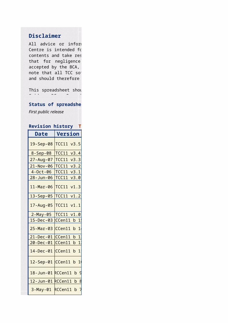
Disclaimer
Status of spreadsheet
First public release
Date Version
19-Sep-08 TCC11 v3.5
8-Sep-08 TCC11 v3.4
27-Aug-07 TCC11 v3.3
21-Nov-06 TCC11 v3.24-Oct-06 TCC11 v3.128-Jun-06 TCC11 v3.0
11-Mar-06 TCC11 v1.3
13-Sep-05 TCC11 v1.2
17-Aug-05 TCC11 v1.1
2-May-05 TCC11 v1.015-Dec-03 RCCen11 b 15
25-Mar-03 RCCen11 b 14
21-Dec-01 RCCen11 b 1320-Dec-01 RCCen11 b 12
14-Dec-01 RCCen11 b 11
12-Sep-01 RCCen11 b 10
18-Jun-01 RCCen11 b 9
12-Jun-01 RCCen11 b 8
3-May-01 RCCen11 b 7
All advice or information from the British Cement Association and/or The Concrete Centre is intended for those who will evaluate the significance and limitations of its contents and take responsibility for its use and application. No liability (including that for negligence) for any loss resulting from such advice or information is accepted by the BCA, TCC or their subcontractors, suppliers or advisors. Users should note that all TCC software and publications are subject to revision from time to time and should therefore ensure that they are in possession of the latest version.
This spreadsheet should be used in compliance with the accompanying publication 'User Guide RC Spreadsheets: v3' available from The Concrete Bookshop, www.concretebookshop.com, Tel +44 (0)700 4 607777 or +44 (0)1276 607140
Revision history TCC11 Element Design
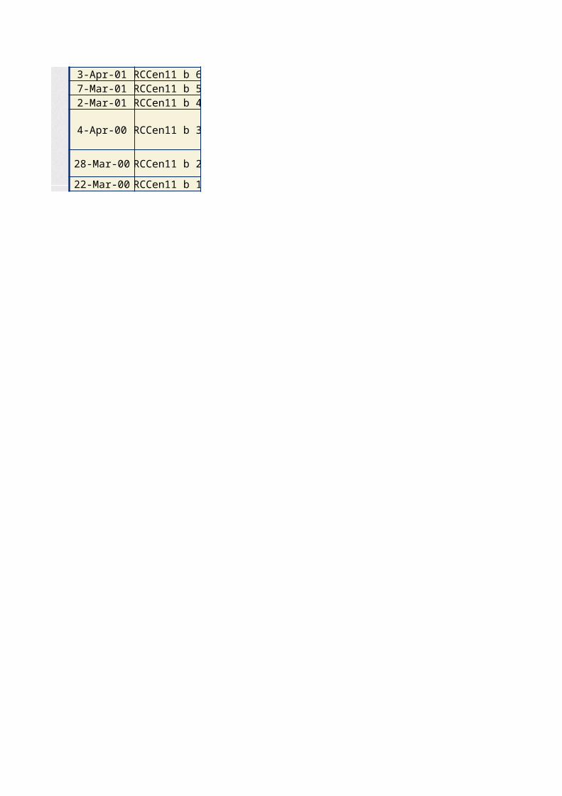
3-Apr-01 RCCen11 b 67-Mar-01 RCCen11 b 52-Mar-01 RCCen11 b 4
4-Apr-00 RCCen11 b 3
28-Mar-00 RCCen11 b 2
22-Mar-00 RCCen11 b 1
Action
788
Correction to x limit at TEE~BEAM M8. 787
766
Improvement to L/d calculation. 761Corrections to text in SLAB!C25, COLUMN!K7 and COLUMN! K11 760
v3 release. Page nos, User Guide and registration details amended. 760
773
Placement setting of controls set to 1. 778
778
RE-BADGED 768Page added for indirect supports. 479
305
Expression for Asw/S (max) corrected on SHEAR. 311R Moss comments incorporated. 310
311
312
239
Correction to strain calculation in COLUMN 241
239
All advice or information from the British Cement Association and/or The Concrete Centre is intended for those who will evaluate the significance and limitations of its contents and take responsibility for its use and application. No liability (including that for negligence) for any loss resulting from such advice or information is accepted by the BCA, TCC or their subcontractors, suppliers or advisors. Users should note that all TCC software and publications are subject to revision from time to time and should therefore ensure that they are in possession of the latest version.
This spreadsheet should be used in compliance with the accompanying publication 'User Guide RC Spreadsheets: v3' available from The Concrete Bookshop, www.concretebookshop.com, Tel +44 (0)700 4 607777 or +44 (0)1276 607140
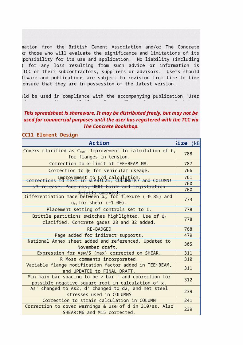
This spreadsheet is shareware. It may be distributed freely, but may not be used for commercial purposes until the user has
registered with the TCC via The Concrete Bookshop.
Revision history TCC11 Element Design
Size (kB)
Covers clarified as Cnom. Improvement to calculation of bt for flanges in tension.
Correction to ψ2 for vehicular useage.
Differentiation made between αcc for flexure (=0.85) and αcc for shear (=1.00).
Brittle partitions switches highlighted. Use of ψ2 clarified. Concrete gades 28 and 32 added.
National Annex sheet added and referenced. Updated to November draft.
Variable flange modification factor added in TEE~BEAM, and UPDATED to FINAL DRAFT.
Min main bar spacing to be > bar f and coorection for possible negative square root in calculation of x.
As' changed to As2, d' changed to d2, and net steel stresses used in COLUMNS
Correction to cover warnings & use of d in 310/ss. Also SHEAR:M6 and M15 corrected.
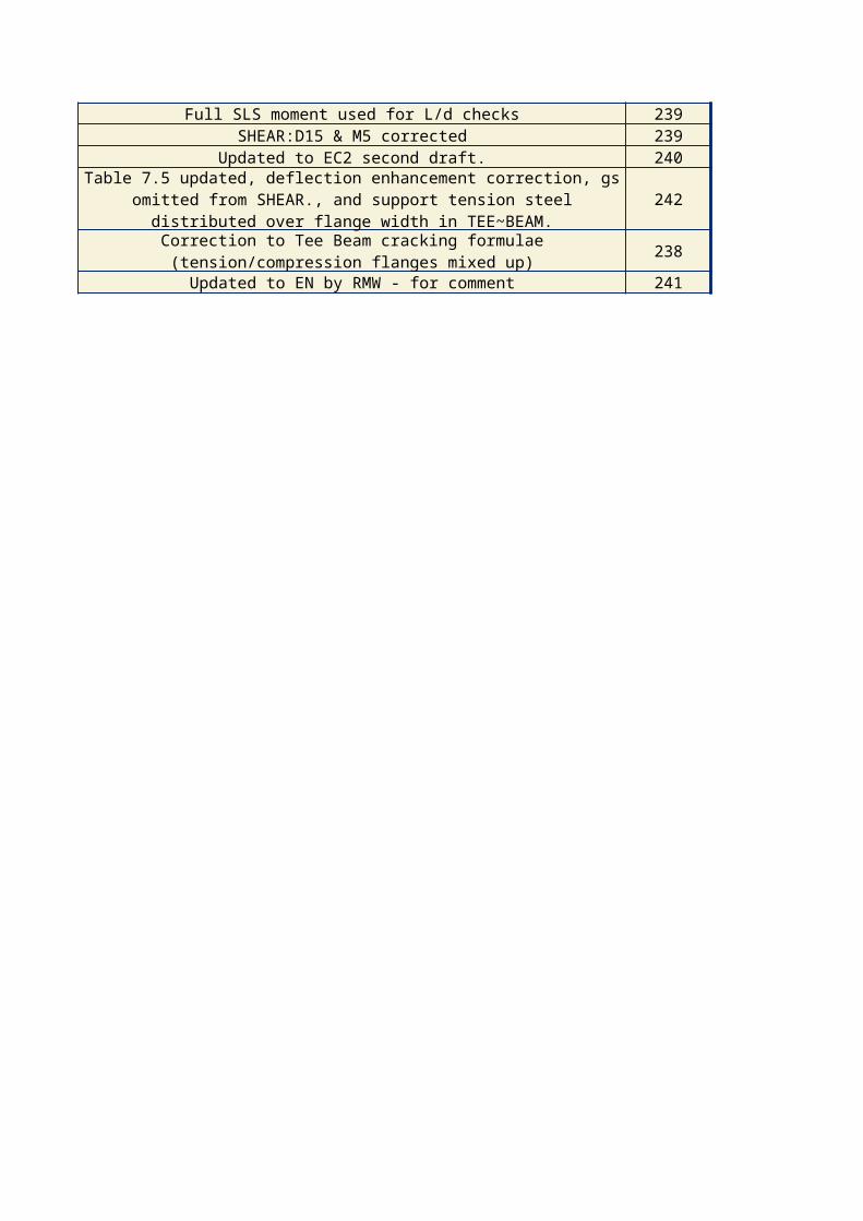
Full SLS moment used for L/d checks 239SHEAR:D15 & M5 corrected 239
Updated to EC2 second draft. 240
242
238
Updated to EN by RMW - for comment 241
Table 7.5 updated, deflection enhancement correction, gs omitted from SHEAR., and support tension steel distributed over flange width in
TEE~BEAM.
Correction to Tee Beam cracking formulae (tension/compression flanges mixed up)
Size (kB)