TAU - status December 14. Lab setup 9/7/2011TAU - status report2 Each RO line is X100 Attenuated and...
13
TAU - status December 14
-
Upload
gertrude-glenn -
Category
Documents
-
view
215 -
download
0
Transcript of TAU - status December 14. Lab setup 9/7/2011TAU - status report2 Each RO line is X100 Attenuated and...

TAU - status
December 14
TAU - status report 2
Lab setup
9/7/2011
Each RO line is X100 Attenuated and 100Ω terminated
10 μm position precision of collimated source
Discriminator
10 RO lines
VME V560counter
HV line quenched with 20MΩ connected to a 1MΩ /100MΩ voltage divider
TAU - status report 3
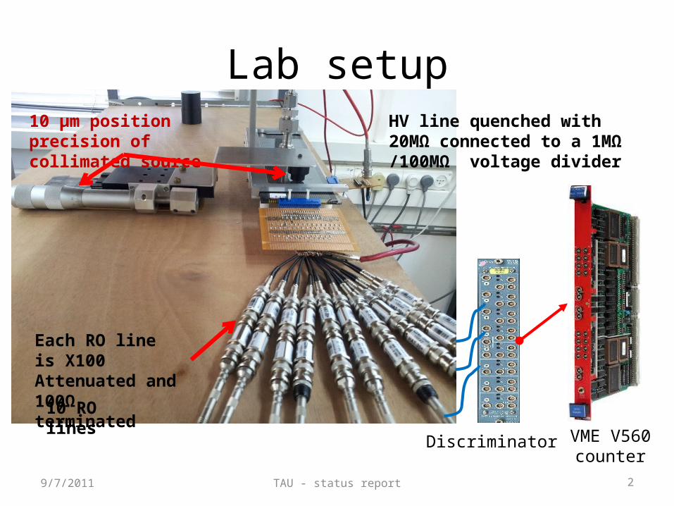
Source position
9/7/2011
Source sits here
1cm thick, Delrin collimator, with a 3 mm slit opening
TAU - status report 4
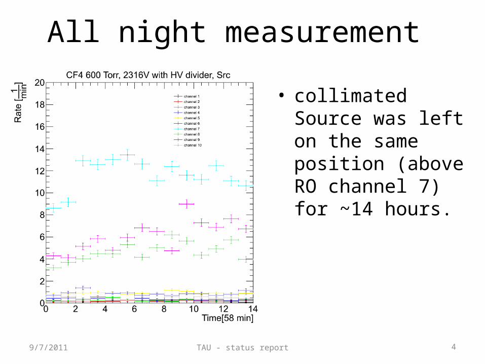
All night measurement
• collimated Source was left on the same position (above RO channel 7) for ~14 hours.
9/7/2011
TAU - status report 59/7/2011
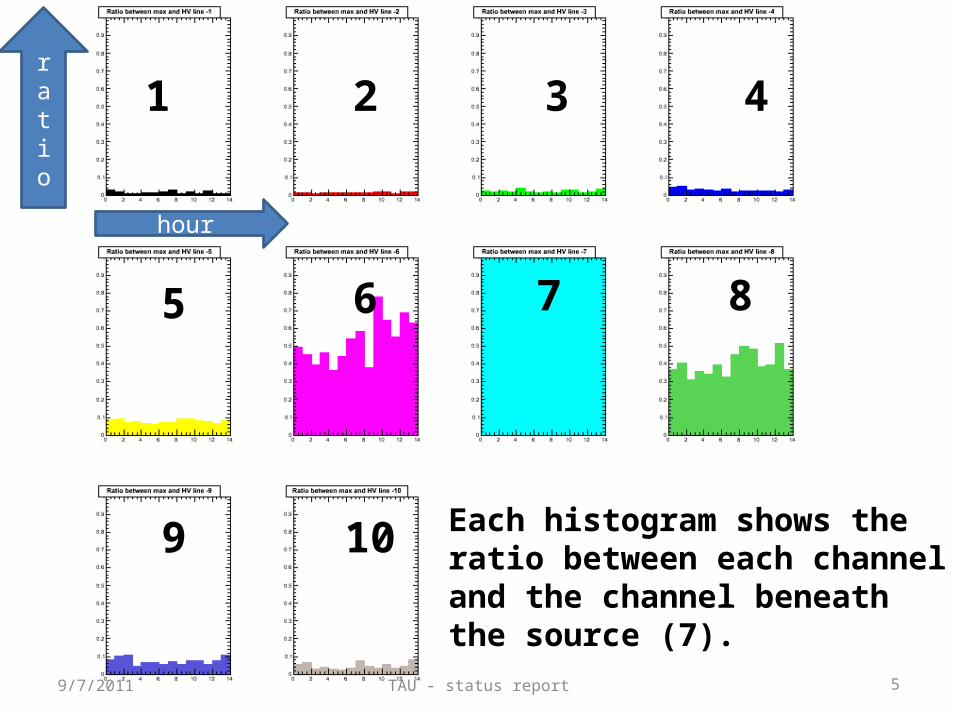
Each histogram shows the ratio between each channel and the channel beneath the source (7).
hour
ratio
1 2 3 4
5 6 7 8
9 10
TAU - status report 6
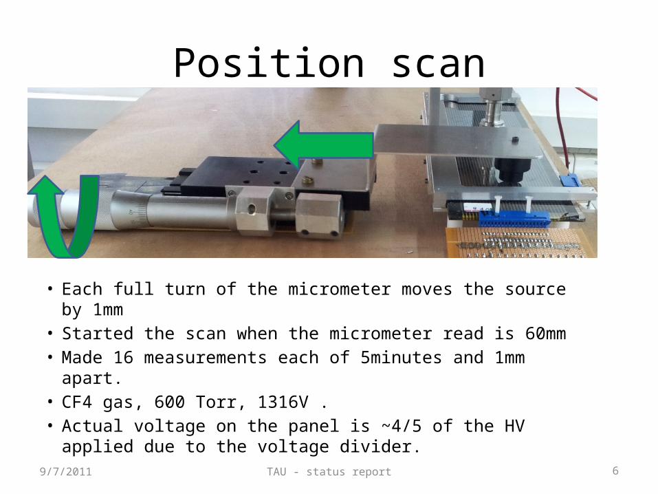
Position scan
• Each full turn of the micrometer moves the source by 1mm• Started the scan when the micrometer read is 60mm• Made 16 measurements each of 5minutes and 1mm apart. • CF4 gas, 600 Torr, 1316V .• Actual voltage on the panel is ~4/5 of the HV applied due
to the voltage divider.9/7/2011
TAU - status report 79/7/2011
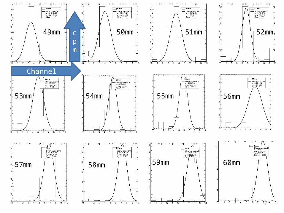
49mm 50mm 51mm 52mm
53mm 54mm 55mm 56mm
60mm 59mm 58mm 57mm
cpm
Channel
TAU - status report 8
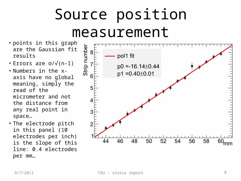
Source position measurement
9/7/2011
• points in this graph are the Gaussian fit results
• Errors are σ/√(n-1)• Numbers in the x-axis
have no global meaning, simply the read of the micrometer and not the distance from any real point in space…
• The electrode pitch in this panel (10 electrodes per inch) is the slope of this line: 0.4 electrodes per mm…
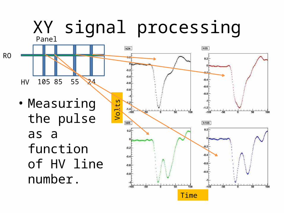
XY signal processing
• Measuring the pulse as a function of HV line number.
RO
85 24105 55
Volts
Time
Panel
HV
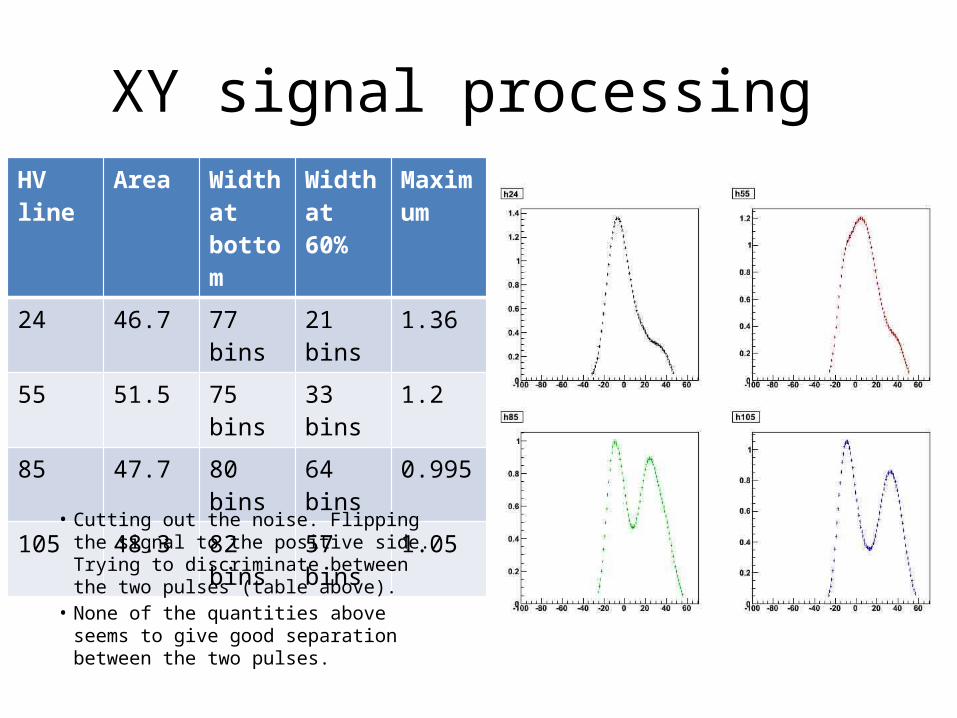
HV line Area Width at bottom
Width at 60%
Maximum
24 46.7 77 bins 21 bins 1.36
55 51.5 75 bins 33 bins 1.2
85 47.7 80 bins 64 bins 0.995
105 48.3 82 bins 57 bins 1.05
XY signal processing
• Cutting out the noise. Flipping the signal to the positive side. Trying to discriminate between the two pulses (table above).
• None of the quantities above seems to give good separation between the two pulses.
TAU - status report 11
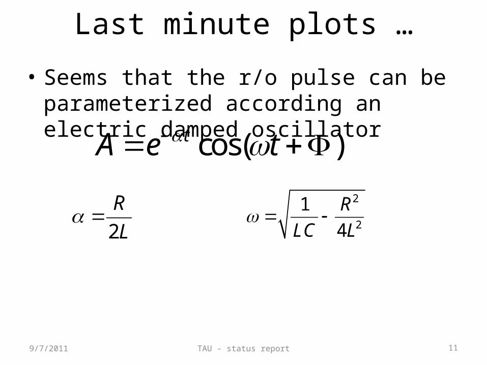
Last minute plots …
• Seems that the r/o pulse can be parameterized according an electric damped oscillator
9/7/2011
cos( )tA e t
2
R
L
2
2
1
4
R
LC L
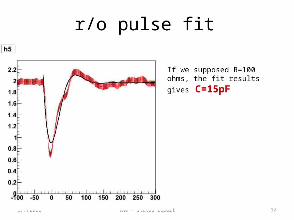
TAU - status report 12
r/o pulse fit
9/7/2011
If we supposed R=100 ohms, the
fit results gives C=15pF
Future plans
• Measuring the signal at stripe #1, we expect to get the signal shape with a factor 2. This should include the negative side of the bi-polar signal.
• Fitting the two pulses with the shape extracted from the above measurement. Allowing the location of the two signals to float.