Tackling the Sonar Equation - UW Courses Web Servercourses.washington.edu/fish538/lectureNotes/Sonar...
31
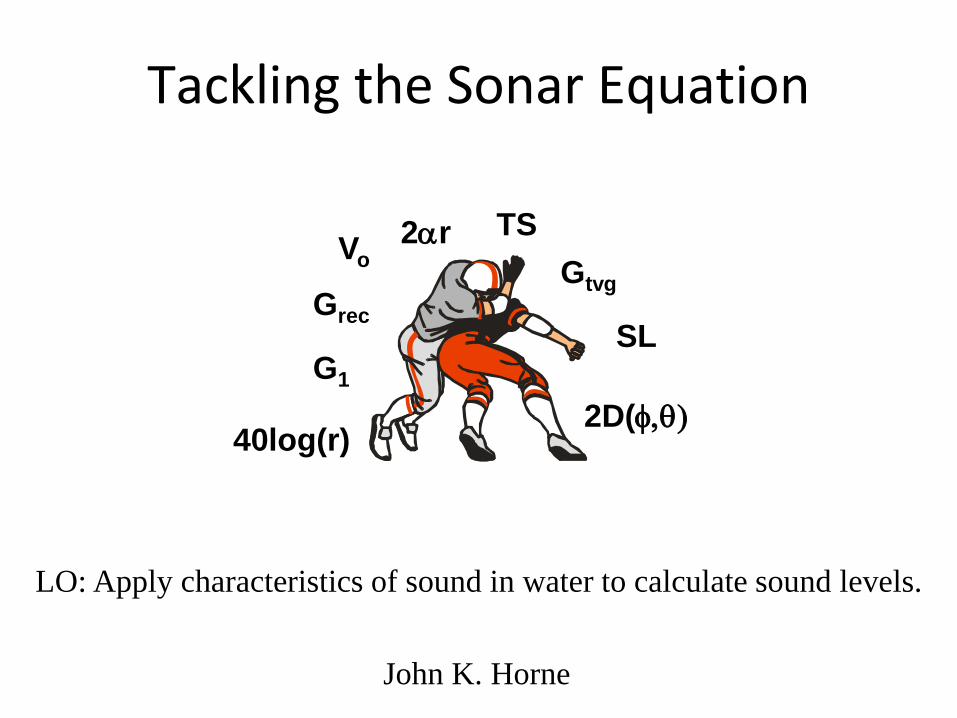
Tackling the Sonar Equation John K. Horne V o SL G 1 TS 2D(φ,θ) 40log(r) 2αr G tvg G rec LO: Apply characteristics of sound in water to calculate sound levels.
Transcript of Tackling the Sonar Equation - UW Courses Web Servercourses.washington.edu/fish538/lectureNotes/Sonar...
Tackling the Sonar Equation
John K. Horne
Vo
SL G1
TS
2D(φ,θ) 40log(r)
2αr Gtvg
Grec
LO: Apply characteristics of sound in water to calculate sound levels.
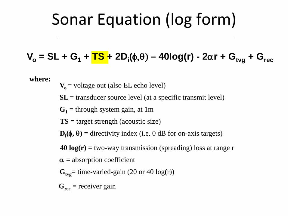
Sonar Equation: Single Target
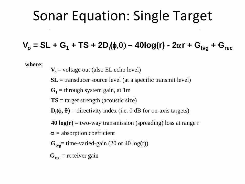
Vo = SL + G1 + TS + 2Di(φ,θ) – 40log(r) - 2αr + Gtvg + Grec
where: Vo = voltage out (also EL echo level)
SL = transducer source level (at a specific transmit level)
G1 = through system gain, at 1m
TS = target strength (acoustic size)
Di(φ, θ) = directivity index (i.e. 0 dB for on-axis targets)
40 log(r) = two-way transmission (spreading) loss at range r
α = absorption coefficient
Gtvg= time-varied-gain (20 or 40 log(r))
Grec = receiver gain
Source Level Cal Measurement
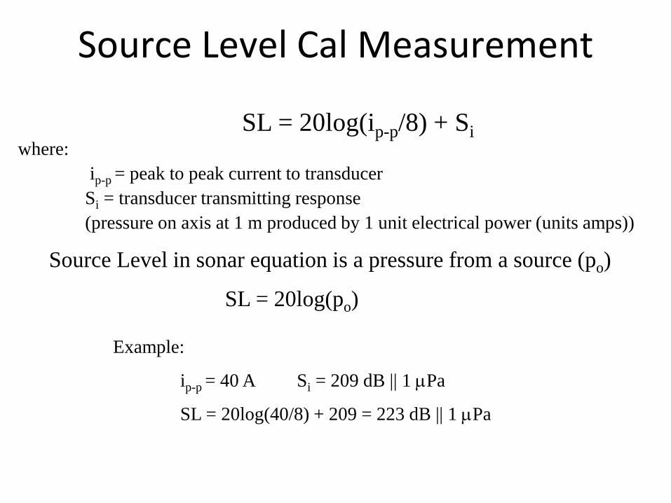
SL = 20log(ip-p/8) + Si where: ip-p = peak to peak current to transducer Si = transducer transmitting response (pressure on axis at 1 m produced by 1 unit electrical power (units amps))
Example:
ip-p = 40 A Si = 209 dB || 1 µPa
SL = 20log(40/8) + 209 = 223 dB || 1 µPa
SL = 20log(po)
Source Level in sonar equation is a pressure from a source (po)
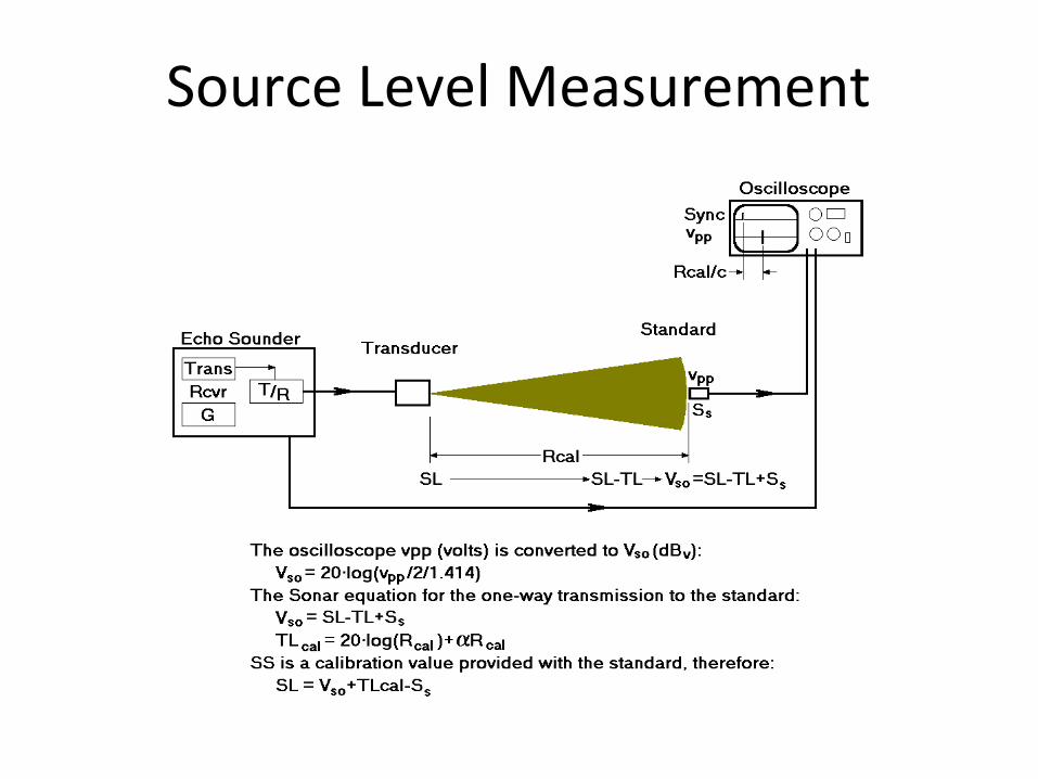
Source Level Measurement
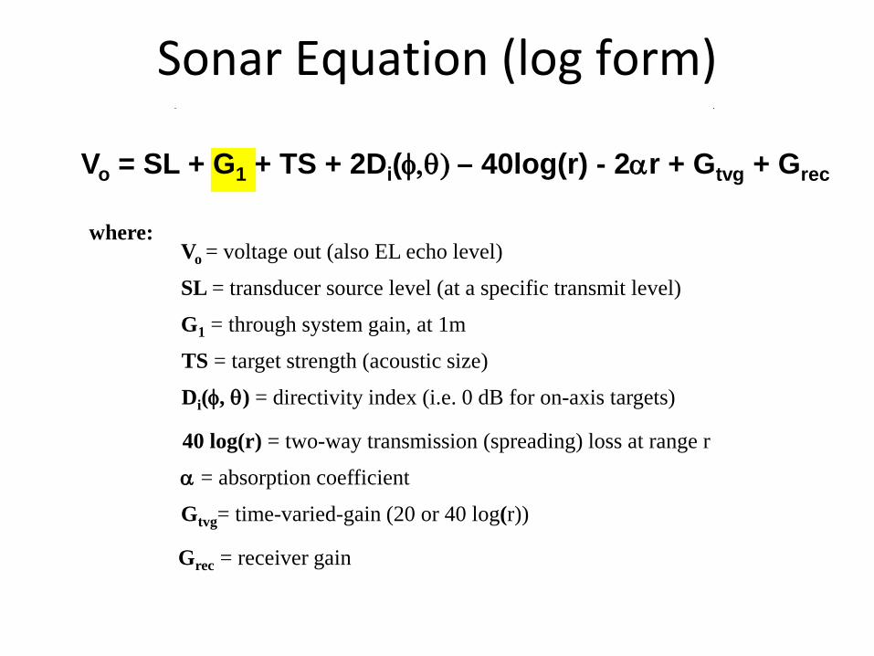
Sonar Equation (log form)
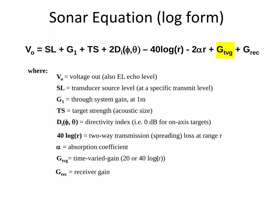
Vo = SL + G1 + TS + 2Di(φ,θ) – 40log(r) - 2αr + Gtvg + Grec
where: Vo = voltage out (also EL echo level)
SL = transducer source level (at a specific transmit level)
G1 = through system gain, at 1m
TS = target strength (acoustic size)
Di(φ, θ) = directivity index (i.e. 0 dB for on-axis targets)
40 log(r) = two-way transmission (spreading) loss at range r
α = absorption coefficient
Gtvg= time-varied-gain (20 or 40 log(r))
Grec = receiver gain
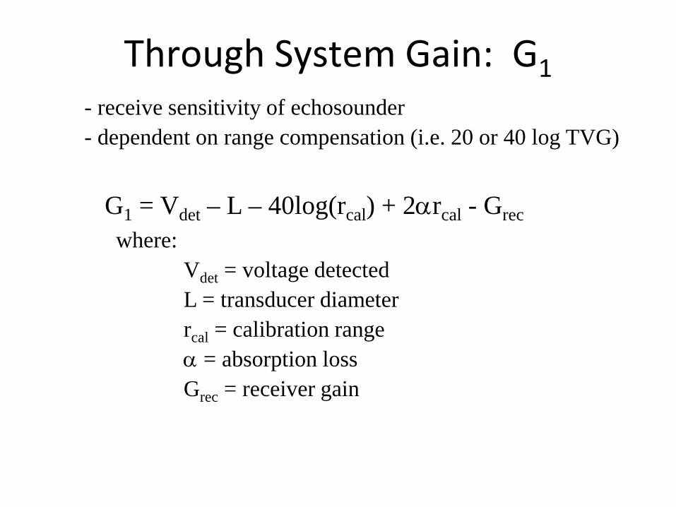
Through System Gain: G1 - receive sensitivity of echosounder - dependent on range compensation (i.e. 20 or 40 log TVG)
G1 = Vdet – L – 40log(rcal) + 2αrcal - Grec where: Vdet = voltage detected L = transducer diameter rcal = calibration range α = absorption loss Grec = receiver gain
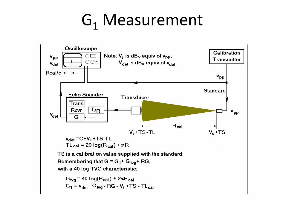
G1 Measurement
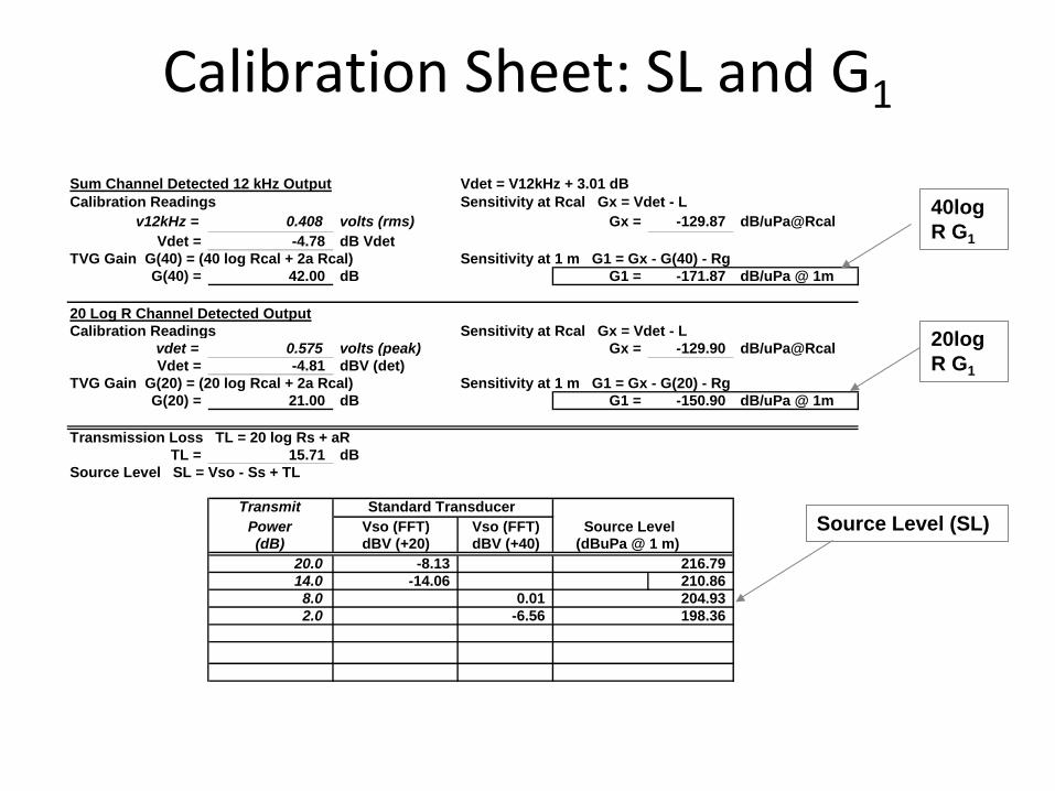
Calibration Sheet: SL and G1
20 Log R Channel Detected OutputCalibration Readings Sensitivity at Rcal Gx = Vdet - L
vdet = 0.575 volts (peak) Gx = -129.90 dB/uPa@RcalVdet = -4.81 dBV (det)
TVG Gain G(20) = (20 log Rcal + 2a Rcal) Sensitivity at 1 m G1 = Gx - G(20) - RgG(20) = 21.00 dB G1 = -150.90 dB/uPa @ 1m
Transmission Loss TL = 20 log Rs + aRTL = 15.71 dB
Source Level SL = Vso - Ss + TL
Transmit Standard TransducerPower Vso (FFT) Vso (FFT) Source Level(dB) dBV (+20) dBV (+40) (dBuPa @ 1 m)
20.0 -8.13 216.7914.0 -14.06 210.868.0 0.01 204.932.0 -6.56 198.36
Sum Channel Detected 12 kHz Output Vdet = V12kHz + 3.01 dBCalibration Readings Sensitivity at Rcal Gx = Vdet - L
v12kHz = 0.408 volts (rms) Gx = -129.87 dB/uPa@RcalVdet = -4.78 dB Vdet
TVG Gain G(40) = (40 log Rcal + 2a Rcal) Sensitivity at 1 m G1 = Gx - G(40) - RgG(40) = 42.00 dB G1 = -171.87 dB/uPa @ 1m
40log R G1
20log R G1
Source Level (SL)
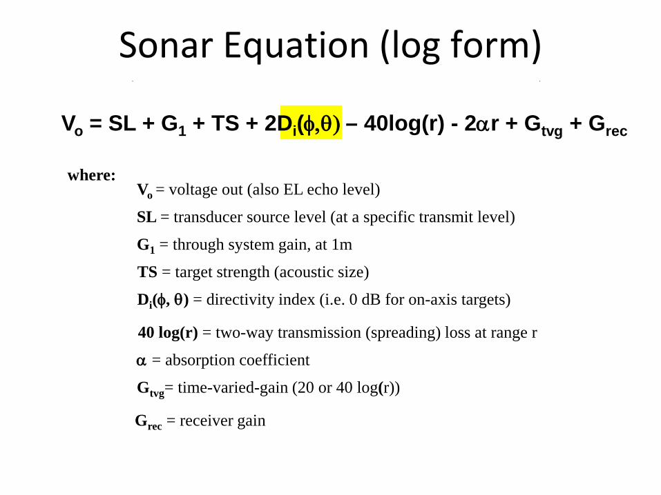
Sonar Equation (log form)
Vo = SL + G1 + TS + 2Di(φ,θ) – 40log(r) - 2αr + Gtvg + Grec
where: Vo = voltage out (also EL echo level)
SL = transducer source level (at a specific transmit level)
G1 = through system gain, at 1m
TS = target strength (acoustic size)
Di(φ, θ) = directivity index (i.e. 0 dB for on-axis targets)
40 log(r) = two-way transmission (spreading) loss at range r
α = absorption coefficient
Gtvg= time-varied-gain (20 or 40 log(r))
Grec = receiver gain
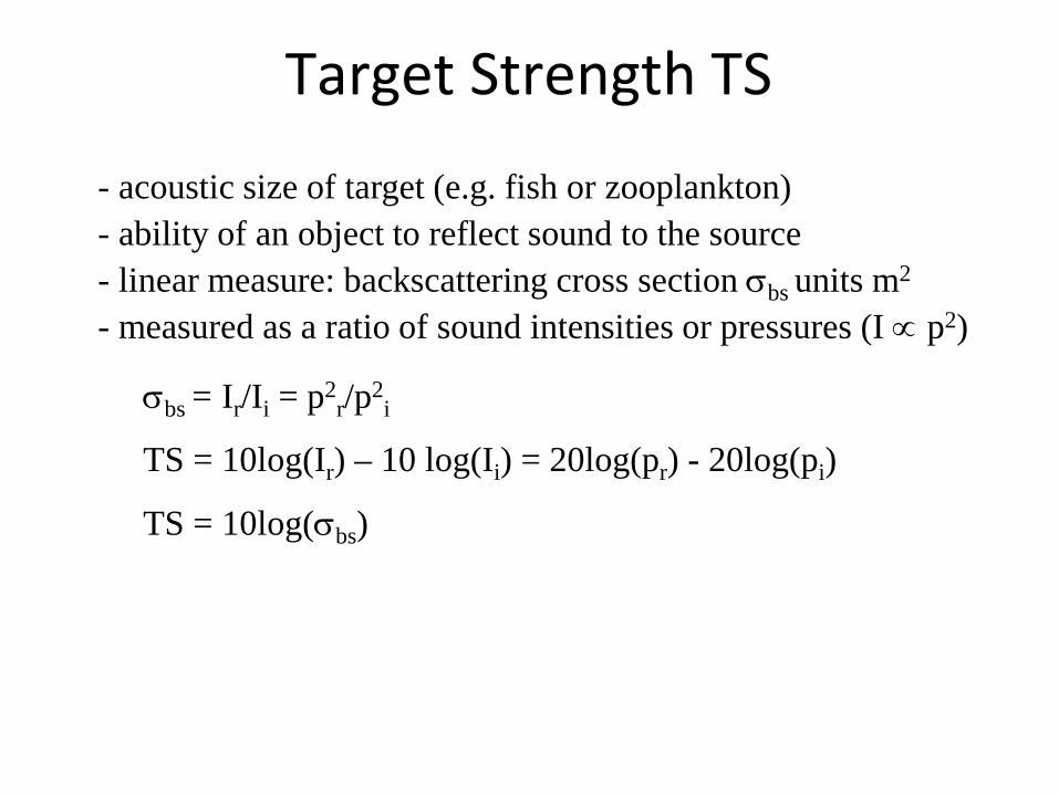
Target Strength TS
- acoustic size of target (e.g. fish or zooplankton) - ability of an object to reflect sound to the source - linear measure: backscattering cross section σbs units m2
- measured as a ratio of sound intensities or pressures (I ∝ p2)
σbs = Ir/Ii = p2r/p2
i
TS = 10log(Ir) – 10 log(Ii) = 20log(pr) - 20log(pi)
TS = 10log(σbs)
Sonar Equation (log form)
Vo = SL + G1 + TS + 2Di(φ,θ) – 40log(r) - 2αr + Gtvg + Grec
where: Vo = voltage out (also EL echo level)
SL = transducer source level (at a specific transmit level)
G1 = through system gain, at 1m
TS = target strength (acoustic size)
Di(φ, θ) = directivity index (i.e. 0 dB for on-axis targets)
40 log(r) = two-way transmission (spreading) loss at range r
α = absorption coefficient
Gtvg= time-varied-gain (20 or 40 log(r))
Grec = receiver gain
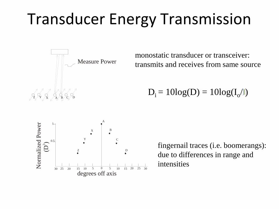
Transducer Energy Transmission
Z Y X A B C D
Measure Power
1
0.5
30 25 20 15 10 5 0 5 10 15 20 25 30
(D)2
degrees off axis
Z
Y
X
A
B
C
D
Nor
mal
ized
Pow
er
monostatic transducer or transceiver: transmits and receives from same source
fingernail traces (i.e. boomerangs): due to differences in range and intensities
Di = 10log(D) = 10log(Io/ )
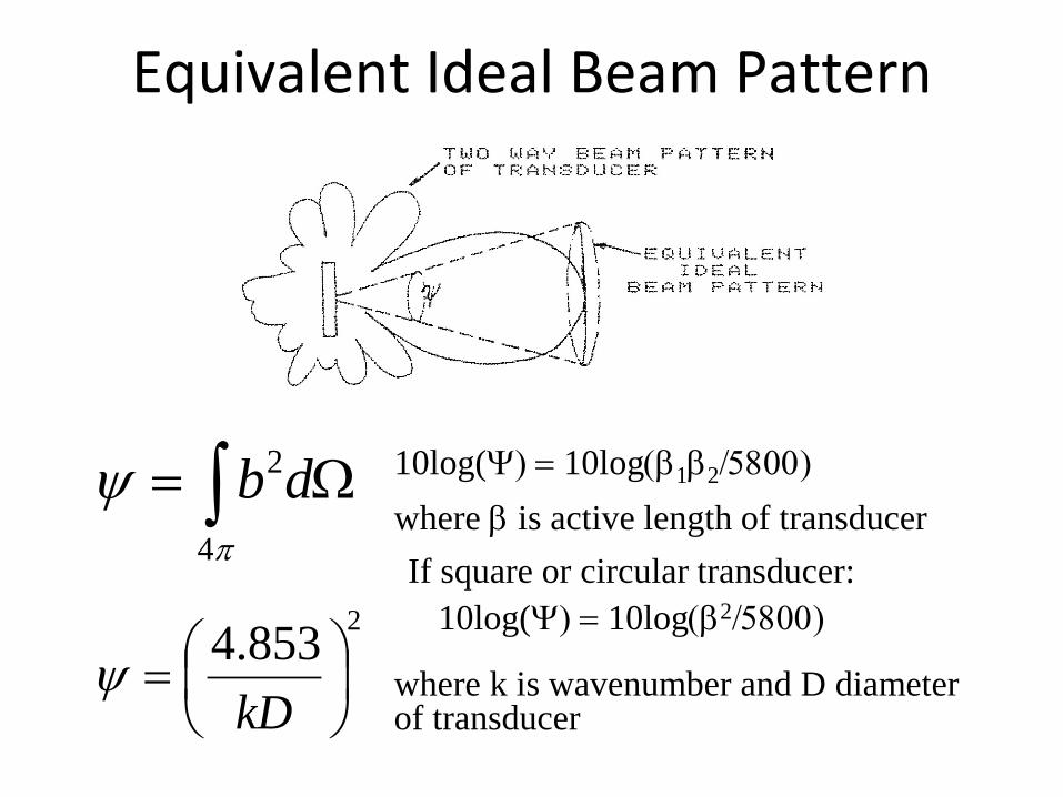
Equivalent Ideal Beam Pattern
10log(Ψ) = 10log(β1β2/5800)
where β is active length of transducer If square or circular transducer:
10log(Ψ) = 10log(β2/5800)
∫ Ω=π
ψ4
2db
2853.4
=
kDψ where k is wavenumber and D diameter
of transducer
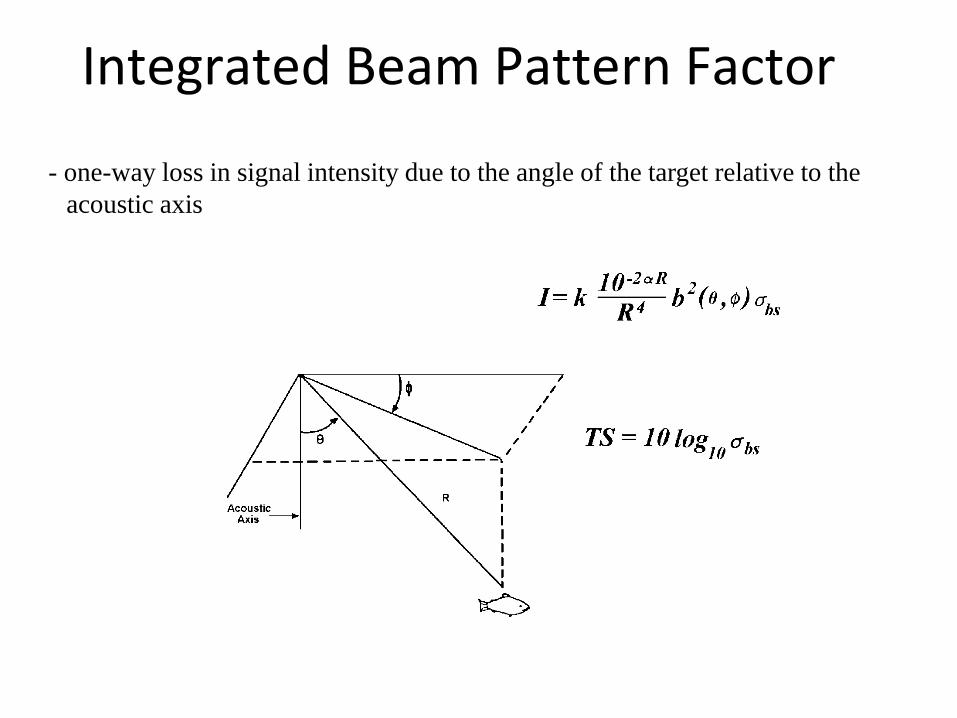
Integrated Beam Pattern Factor
- one-way loss in signal intensity due to the angle of the target relative to the acoustic axis
Effect of Beam Pattern
- transmit response (i.e. acoustic level) is highest along acoustic axis - receive response (i.e. echo level) is highest along acoustic axis - echo received from a target will decrease off axis due to transmit and receive losses - echo amplitude of a target depends on acoustic size of fish and position in beam

Sonar Equation (log form)
Vo = SL + G1 + TS + 2Di(φ,θ) – 40log(r) - 2αr + Gtvg + Grec
where: Vo = voltage out (also EL echo level)
SL = transducer source level (at a specific transmit level)
G1 = through system gain, at 1m
TS = target strength (acoustic size)
Di(φ, θ) = directivity index (i.e. 0 dB for on-axis targets)
40 log(r) = two-way transmission (spreading) loss at range r
α = absorption coefficient
Gtvg= time-varied-gain (20 or 40 log(r))
Grec = receiver gain
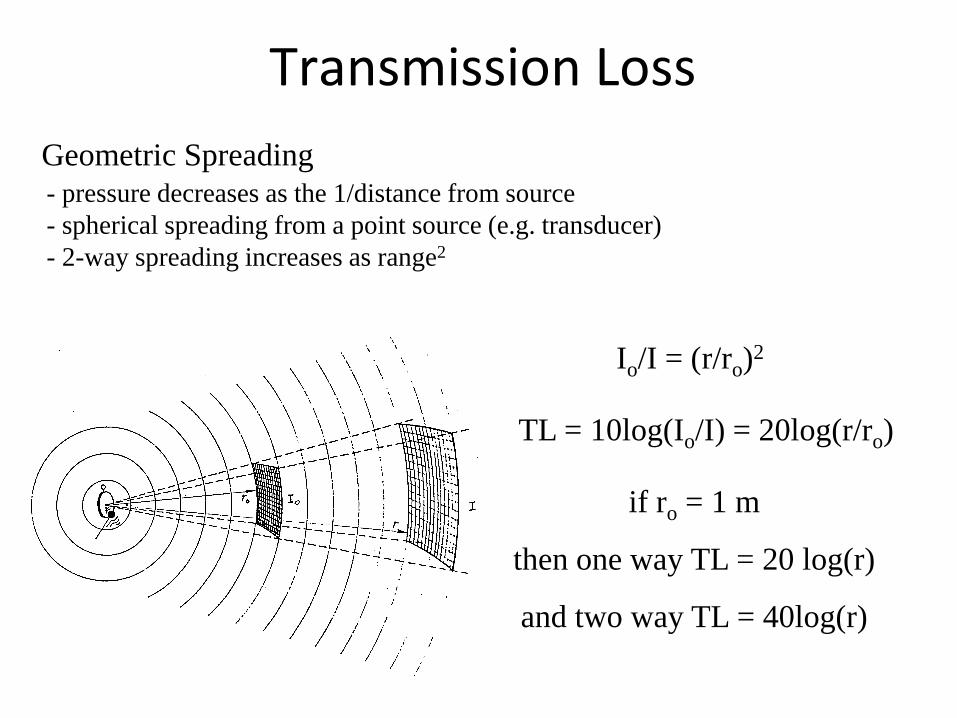
Transmission Loss Geometric Spreading
- pressure decreases as the 1/distance from source - spherical spreading from a point source (e.g. transducer) - 2-way spreading increases as range2
Io/I = (r/ro)2
TL = 10log(Io/I) = 20log(r/ro)
if ro = 1 m
then one way TL = 20 log(r)
and two way TL = 40log(r)
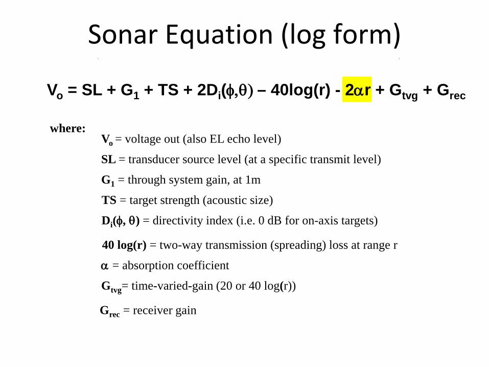
Sonar Equation (log form)
Vo = SL + G1 + TS + 2Di(φ,θ) – 40log(r) - 2αr + Gtvg + Grec
where: Vo = voltage out (also EL echo level)
SL = transducer source level (at a specific transmit level)
G1 = through system gain, at 1m
TS = target strength (acoustic size)
Di(φ, θ) = directivity index (i.e. 0 dB for on-axis targets)
40 log(r) = two-way transmission (spreading) loss at range r
α = absorption coefficient
Gtvg= time-varied-gain (20 or 40 log(r))
Grec = receiver gain
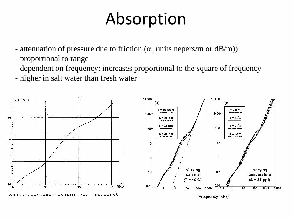
Absorption - attenuation of pressure due to friction (α, units nepers/m or dB/m)) - proportional to range - dependent on frequency: increases proportional to the square of frequency - higher in salt water than fresh water
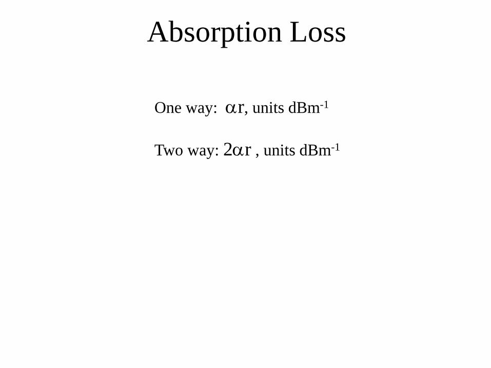
Absorption Loss
One way: αr, units dBm-1
Two way: 2αr , units dBm-1
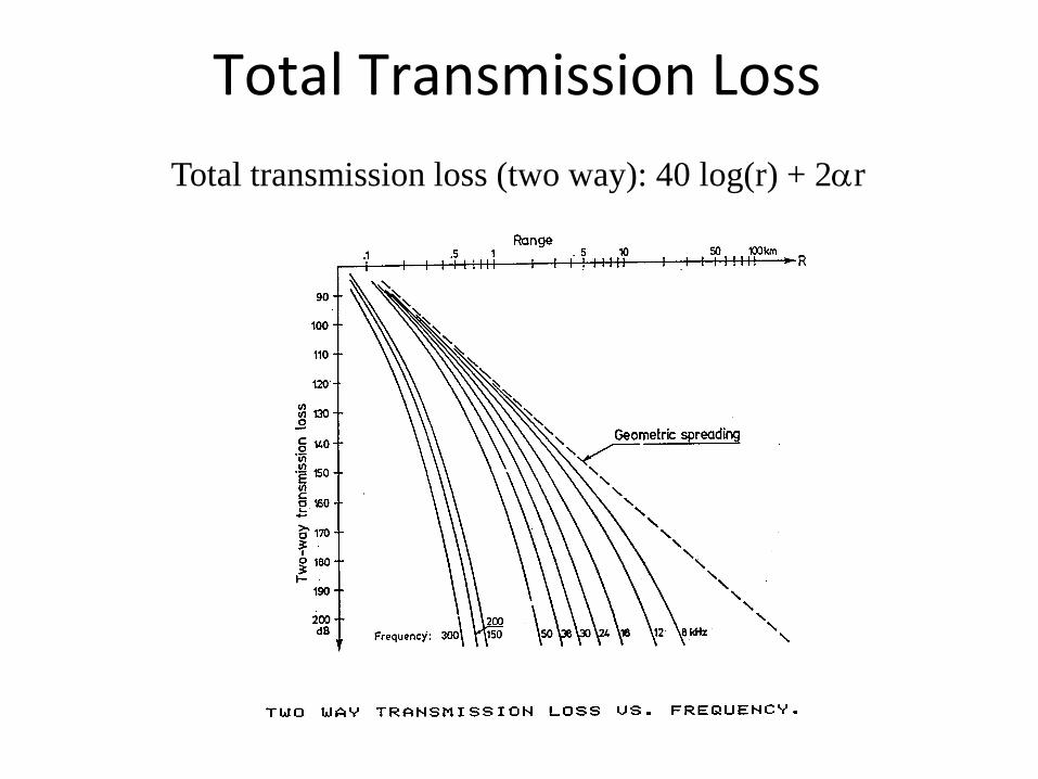
Total Transmission Loss Total transmission loss (two way): 40 log(r) + 2αr
Sonar Equation (log form)
Vo = SL + G1 + TS + 2Di(φ,θ) – 40log(r) - 2αr + Gtvg + Grec
where: Vo = voltage out (also EL echo level)
SL = transducer source level (at a specific transmit level)
G1 = through system gain, at 1m
TS = target strength (acoustic size)
Di(φ, θ) = directivity index (i.e. 0 dB for on-axis targets)
40 log(r) = two-way transmission (spreading) loss at range r
α = absorption coefficient
Gtvg= time-varied-gain (20 or 40 log(r))
Grec = receiver gain
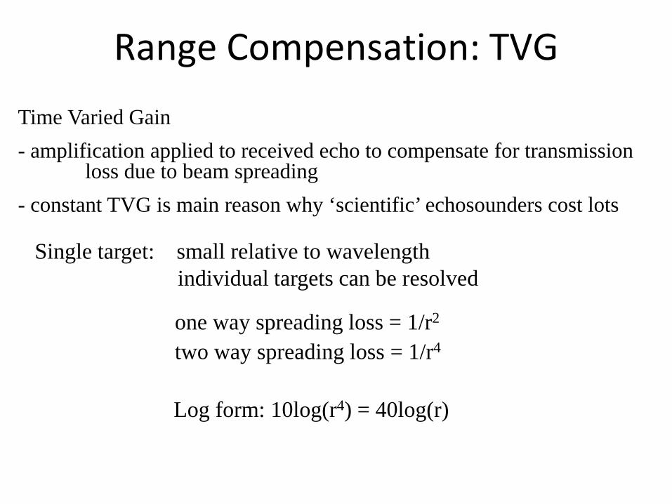
Range Compensation: TVG
Time Varied Gain - amplification applied to received echo to compensate for transmission loss due to beam spreading - constant TVG is main reason why ‘scientific’ echosounders cost lots
Single target: small relative to wavelength individual targets can be resolved
one way spreading loss = 1/r2 two way spreading loss = 1/r4
Log form: 10log(r4) = 40log(r)
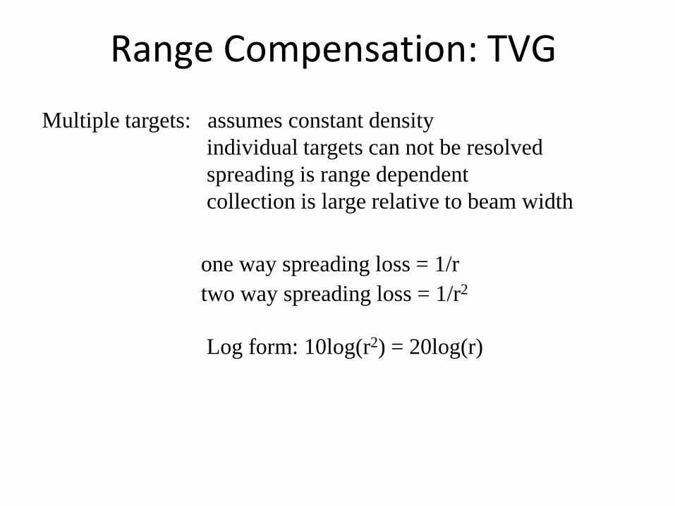
Range Compensation: TVG
Multiple targets: assumes constant density individual targets can not be resolved spreading is range dependent collection is large relative to beam width
one way spreading loss = 1/r two way spreading loss = 1/r2
Log form: 10log(r2) = 20log(r)
TVG Again
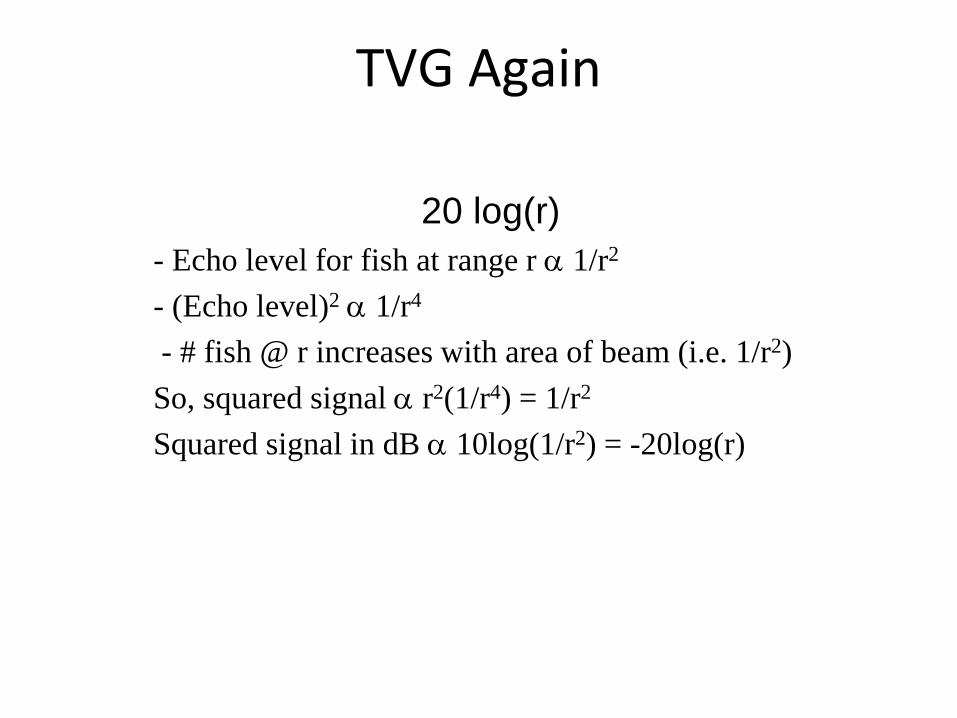
20 log(r) - Echo level for fish at range r α 1/r2
- (Echo level)2 α 1/r4
- # fish @ r increases with area of beam (i.e. 1/r2) So, squared signal α r2(1/r4) = 1/r2 Squared signal in dB α 10log(1/r2) = -20log(r)
Gtvg: Time Varied Gain
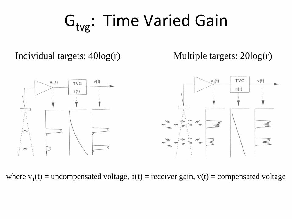
Multiple targets: 20log(r) Individual targets: 40log(r)
where v1(t) = uncompensated voltage, a(t) = receiver gain, v(t) = compensated voltage
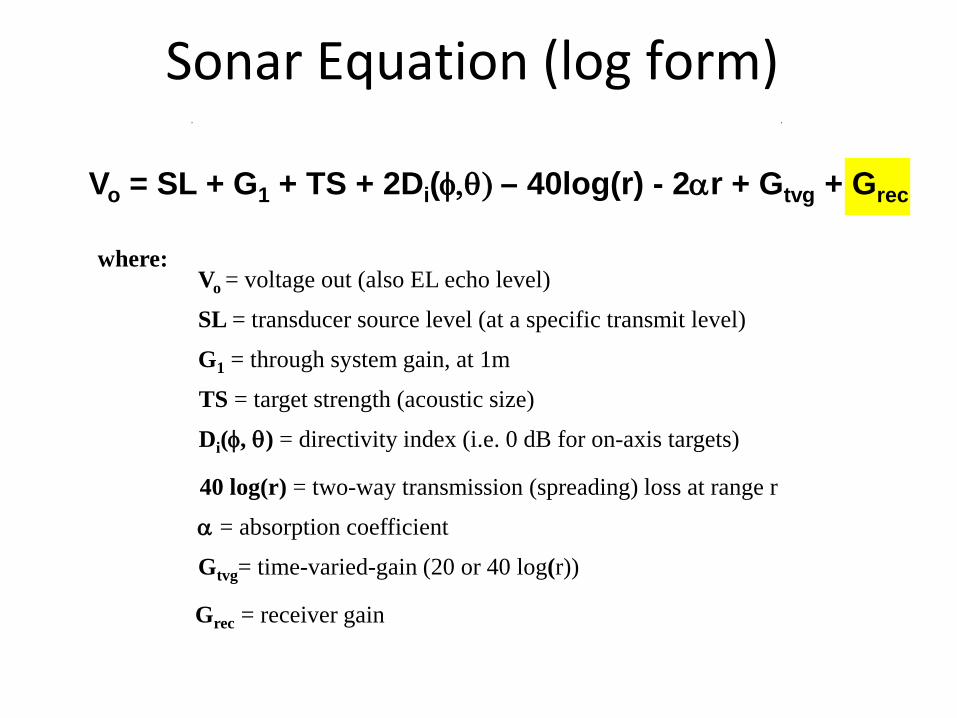
Sonar Equation (log form)
Vo = SL + G1 + TS + 2Di(φ,θ) – 40log(r) - 2αr + Gtvg + Grec
where: Vo = voltage out (also EL echo level)
SL = transducer source level (at a specific transmit level)
G1 = through system gain, at 1m
TS = target strength (acoustic size)
Di(φ, θ) = directivity index (i.e. 0 dB for on-axis targets)
40 log(r) = two-way transmission (spreading) loss at range r
α = absorption coefficient
Gtvg= time-varied-gain (20 or 40 log(r))
Grec = receiver gain
Grec: System Receiver Gain
- amplification applied to received echo to center dynamic range of echosounder
- some manufacturers user selected: range -12 dB to +12 dB
- other manufacturers user sets minimum detected and then adds range (typically 36 dB)
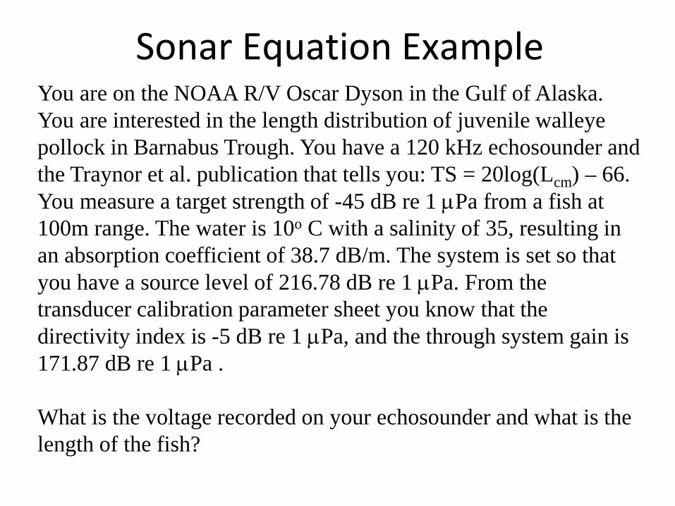
Sonar Equation Example You are on the NOAA R/V Oscar Dyson in the Gulf of Alaska. You are interested in the length distribution of juvenile walleye pollock in Barnabus Trough. You have a 120 kHz echosounder and the Traynor et al. publication that tells you: TS = 20log(Lcm) – 66. You measure a target strength of -45 dB re 1 µPa from a fish at 100m range. The water is 10o C with a salinity of 35, resulting in an absorption coefficient of 38.7 dB/m. The system is set so that you have a source level of 216.78 dB re 1 µPa. From the transducer calibration parameter sheet you know that the directivity index is -5 dB re 1 µPa, and the through system gain is 171.87 dB re 1 µPa . What is the voltage recorded on your echosounder and what is the length of the fish?
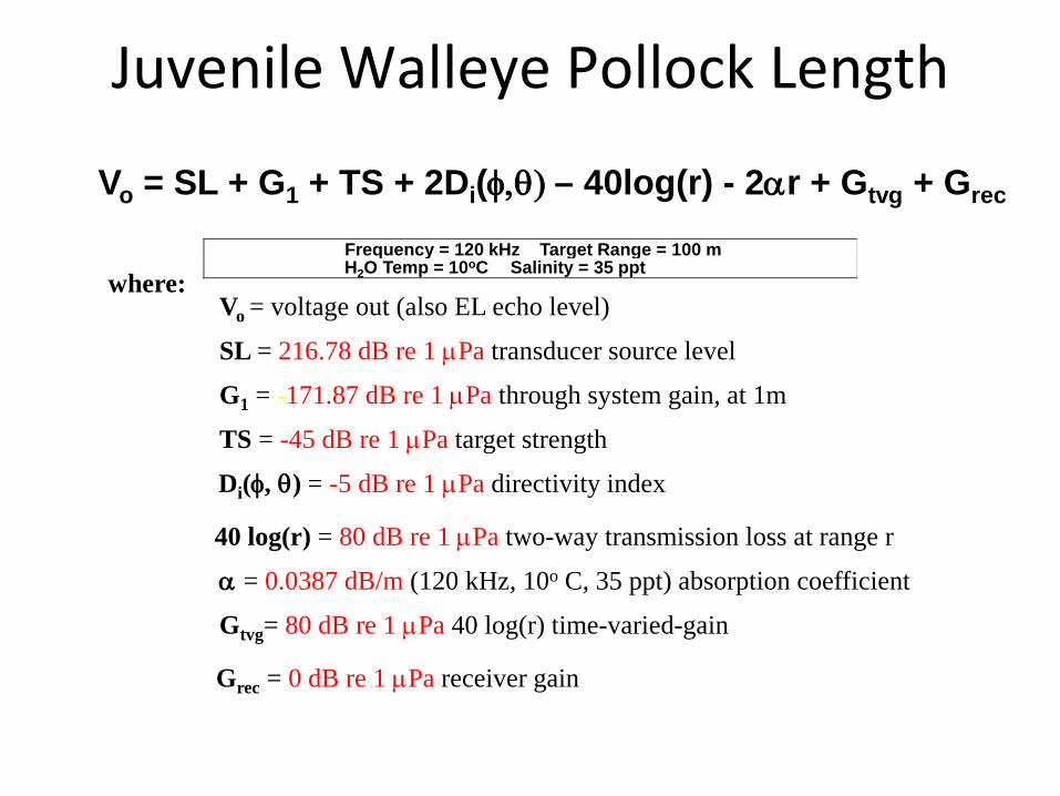
Juvenile Walleye Pollock Length
Vo = SL + G1 + TS + 2Di(φ,θ) – 40log(r) - 2αr + Gtvg + Grec
Frequency = 120 kHz Target Range = 100 m H2O Temp = 10oC Salinity = 35 ppt
where: Vo = voltage out (also EL echo level)
SL = 216.78 dB re 1 µPa transducer source level
G1 = -171.87 dB re 1 µPa through system gain, at 1m
TS = -45 dB re 1 µPa target strength
Di(φ, θ) = -5 dB re 1 µPa directivity index
40 log(r) = 80 dB re 1 µPa two-way transmission loss at range r
α = 0.0387 dB/m (120 kHz, 10o C, 35 ppt) absorption coefficient
Gtvg= 80 dB re 1 µPa 40 log(r) time-varied-gain
Grec = 0 dB re 1 µPa receiver gain
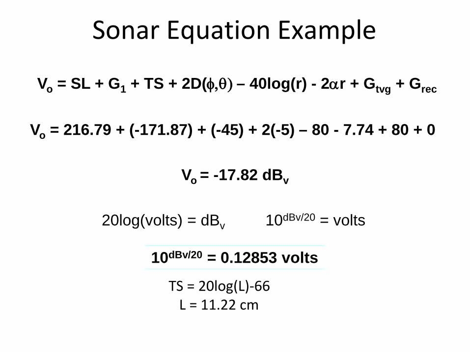
Sonar Equation Example
Vo = 216.79 + (-171.87) + (-45) + 2(-5) – 80 - 7.74 + 80 + 0
Vo = SL + G1 + TS + 2D(φ,θ) – 40log(r) - 2αr + Gtvg + Grec
Vo = -17.82 dBv
20log(volts) = dBv 10dBv/20 = volts
10dBv/20 = 0.12853 volts
TS = 20log(L)-66 L = 11.22 cm