Suspension design Cosmic Explorer
27
Cosmic Explorer Suspension design Sebastien BISCANS GWADW 2021 - Cryogenic Workshop DCC: G2101051 CE DCC: G2100021
Transcript of Suspension design Cosmic Explorer
Cosmic Explorer Suspension designSebastien BISCANSGWADW 2021 - Cryogenic Workshop
DCC: G2101051CE DCC: G2100021
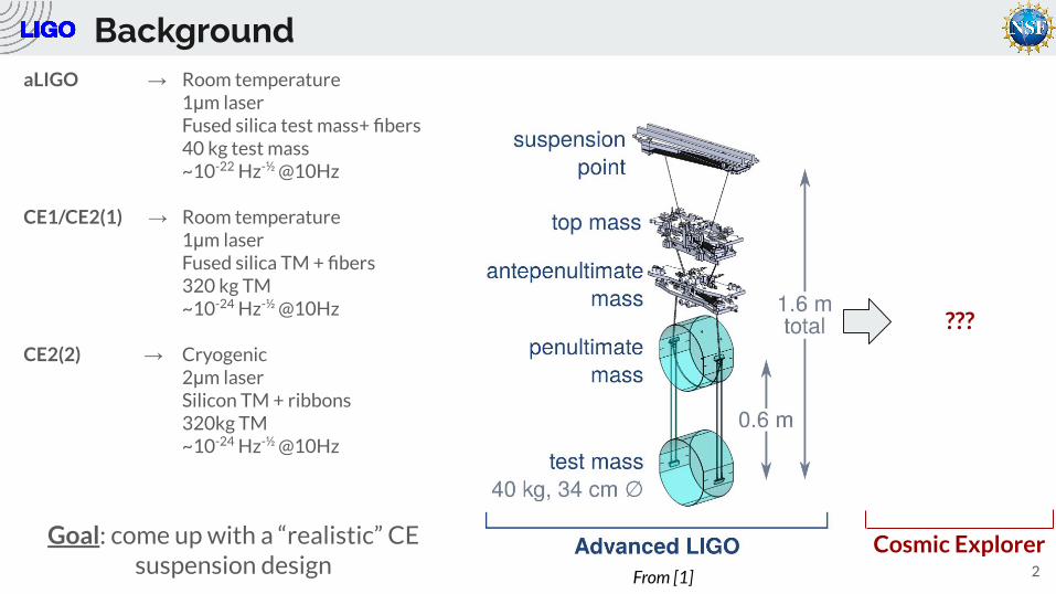
BackgroundaLIGO → Room temperature
1μm laserFused silica test mass+ fibers40 kg test mass~10-22 Hz-½ @10Hz
CE1/CE2(1) → Room temperature1μm laserFused silica TM + fibers320 kg TM~10-24 Hz-½ @10Hz
CE2(2) → Cryogenic2μm laserSilicon TM + ribbons320kg TM~10-24 Hz-½ @10Hz
2
Cosmic Explorer
???
From [1]
Goal: come up with a “realistic” CE suspension design
Outline
1. Requirements / What do we want
2. Silicon
3. Design approach
4. A few concepts
5. Conclusion
3
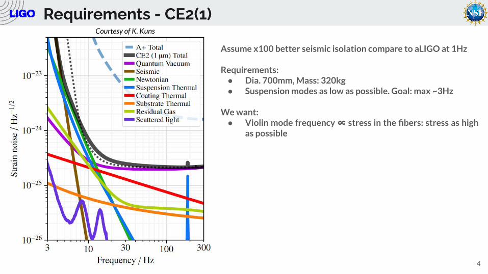
Requirements - CE2(1)
4
Assume x100 better seismic isolation compare to aLIGO at 1Hz
Requirements:● Dia. 700mm, Mass: 320kg● Suspension modes as low as possible. Goal: max ~3Hz
We want:● Violin mode frequency ∝ stress in the fibers: stress as high
as possible
Courtesy of K. Kuns
Requirements - CE2(2)
5
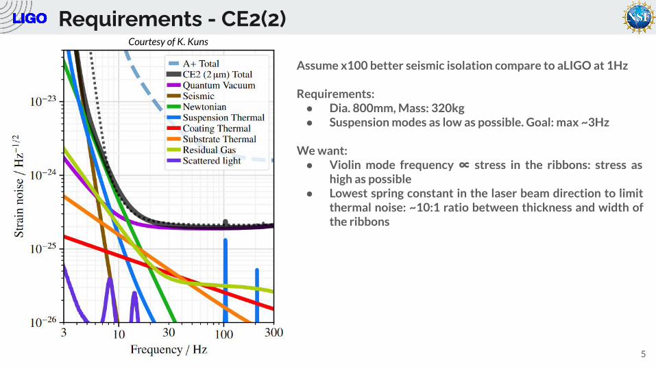
Courtesy of K. Kuns
Assume x100 better seismic isolation compare to aLIGO at 1Hz
Requirements:● Dia. 800mm, Mass: 320kg● Suspension modes as low as possible. Goal: max ~3Hz
We want:● Violin mode frequency ∝ stress in the ribbons: stress as
high as possible● Lowest spring constant in the laser beam direction to limit
thermal noise: ~10:1 ratio between thickness and width of the ribbons
Silicon
6
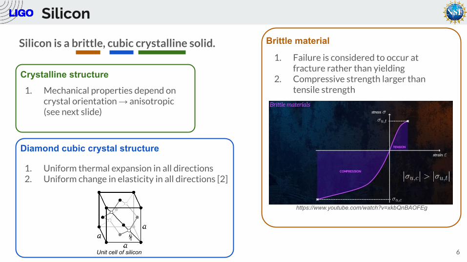
Silicon is a brittle, cubic crystalline solid.
1. Uniform thermal expansion in all directions2. Uniform change in elasticity in all directions [2]
Brittle material
1. Failure is considered to occur at fracture rather than yielding
2. Compressive strength larger than tensile strength
Crystalline structure
1. Mechanical properties depend on crystal orientation → anisotropic (see next slide)
https://www.youtube.com/watch?v=xkbQnBAOFEg
Diamond cubic crystal structure
Unit cell of silicon
Silicon - Young’s modulus and Poisson’s Ratio [3]
7
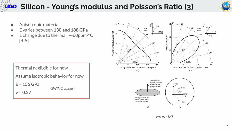
From [3]
● Anisotropic material● E varies between 130 and 188 GPa● E change due to thermal: ~-60ppm/oC
[4-5]
Thermal negligible for now
Assume isotropic behavior for now
E = 155 GPa
ν = 0.27(GWINC values)
Silicon - Tensile strength
8
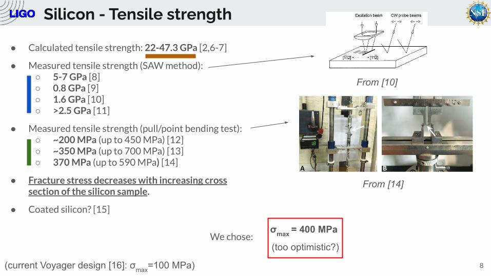
● Calculated tensile strength: 22-47.3 GPa [2,6-7]
● Measured tensile strength (SAW method):○ 5-7 GPa [8]○ 0.8 GPa [9]○ 1.6 GPa [10]○ >2.5 GPa [11]
● Measured tensile strength (pull/point bending test):○ ~200 MPa (up to 450 MPa) [12]○ ~350 MPa (up to 700 MPa) [13]○ 370 MPa (up to 590 MPa) [14]
● Fracture stress decreases with increasing cross section of the silicon sample.
● Coated silicon? [15]
From [10]
σmax = 400 MPa
From [14]
(too optimistic?)
(current Voyager design [16]: σmax=100 MPa)
We chose:
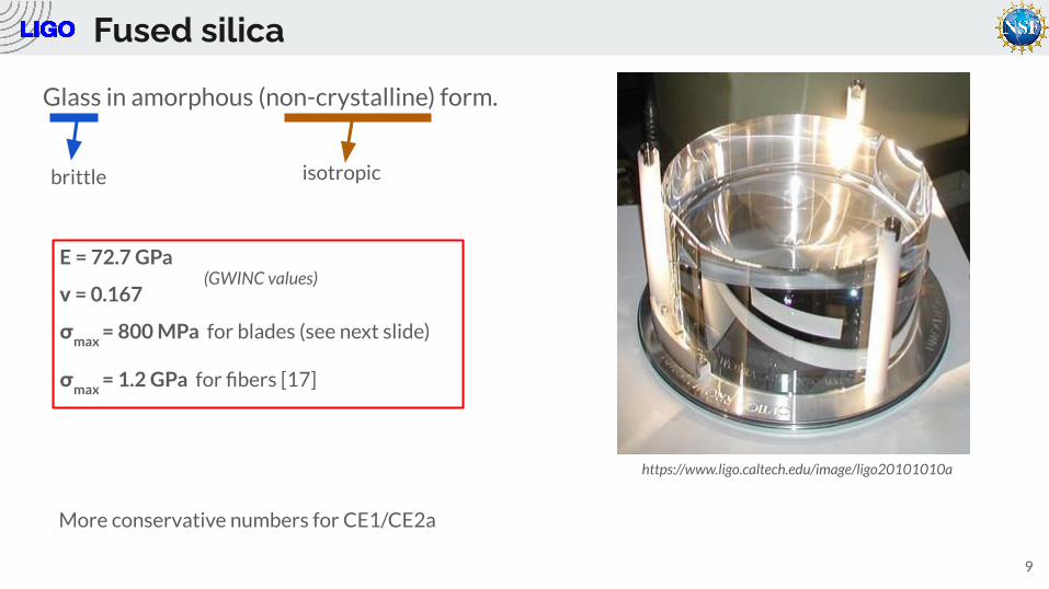
Fused silica
9
Glass in amorphous (non-crystalline) form.
brittle isotropic
E = 72.7 GPa
ν = 0.167
σmax
= 800 MPa for blades (see next slide)
σmax
= 1.2 GPa for fibers [17]
(GWINC values)
https://www.ligo.caltech.edu/image/ligo20101010a
More conservative numbers for CE1/CE2a
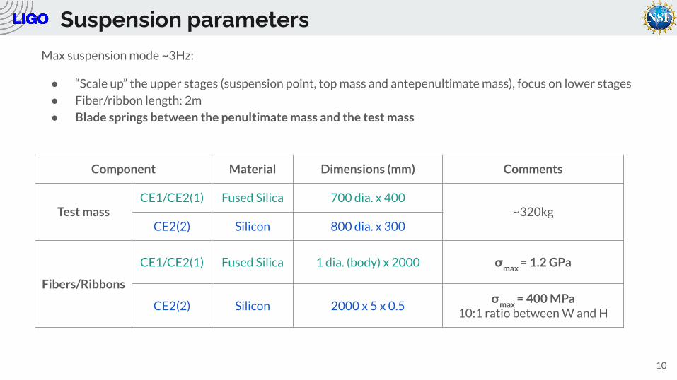
Suspension parametersMax suspension mode ~3Hz:
● “Scale up” the upper stages (suspension point, top mass and antepenultimate mass), focus on lower stages
● Fiber/ribbon length: 2m
● Blade springs between the penultimate mass and the test mass
10
Component Material Dimensions (mm) Comments
Test massCE1/CE2(1) Fused Silica 700 dia. x 400
~320kgCE2(2) Silicon 800 dia. x 300
Fibers/Ribbons
CE1/CE2(1) Fused Silica 1 dia. (body) x 2000 σmax
= 1.2 GPa
CE2(2) Silicon 2000 x 5 x 0.5σ
max = 400 MPa
10:1 ratio between W and H
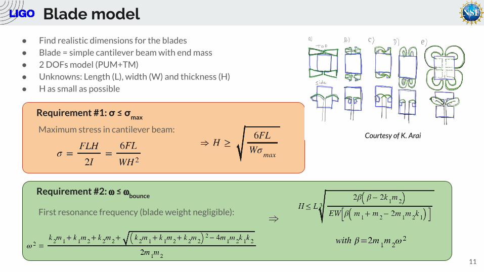
Blade model● Find realistic dimensions for the blades
● Blade = simple cantilever beam with end mass
● 2 DOFs model (PUM+TM)
● Unknowns: Length (L), width (W) and thickness (H)
● H as small as possible
11
Courtesy of K. AraiMaximum stress in cantilever beam:
Requirement #1: σ ≤ σmax
Requirement #2: ⍵ ≤ ⍵bounce
First resonance frequency (blade weight negligible):
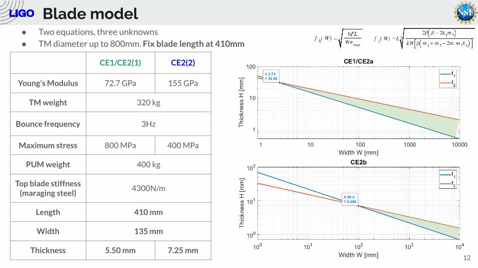
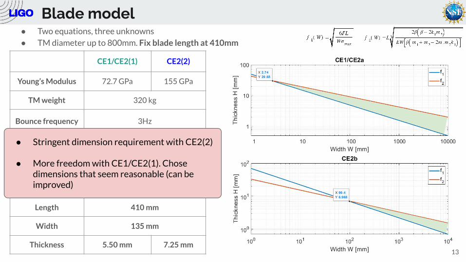
Blade model● Two equations, three unknowns
● TM diameter up to 800mm. Fix blade length at 410mm
12
CE1/CE2(1) CE2(2)
Young’s Modulus 72.7 GPa 155 GPa
TM weight 320 kg
Bounce frequency 3Hz
Maximum stress 800 MPa 400 MPa
PUM weight 400 kg
Top blade stiffness (maraging steel)
4300N/m
Length 410 mm
Width 135 mm
Thickness 5.50 mm 7.25 mm
Blade model● Two equations, three unknowns
● TM diameter up to 800mm. Fix blade length at 410mm
13
CE1/CE2(1) CE2(2)
Young’s Modulus 72.7 GPa 155 GPa
TM weight 320 kg
Bounce frequency 3Hz
Maximum stress 800 MPa 400 MPa
PUM weight 400 kg
Top blade stiffness (maraging steel)
4300N/m
Length 410 mm
Width 135 mm
Thickness 5.50 mm 7.25 mm
● Stringent dimension requirement with CE2(2)
● More freedom with CE1/CE2(1). Chose dimensions that seem reasonable (can be improved)
Concept #1
14
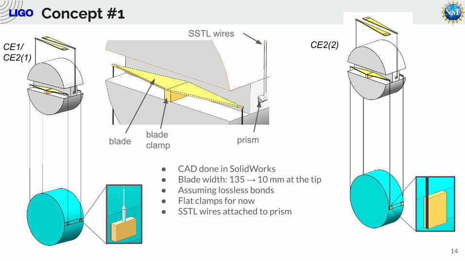
CE1/CE2(1)
CE2(2)
● CAD done in SolidWorks● Blade width: 135 → 10 mm at the tip● Assuming lossless bonds● Flat clamps for now● SSTL wires attached to prism
prism
SSTL wires
blade clampblade
Concept #1
15
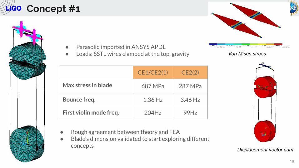
● Parasolid imported in ANSYS APDL● Loads: SSTL wires clamped at the top, gravity
CE1/CE2(1) CE2(2)
Max stress in blade 687 MPa 287 MPa
Bounce freq. 1.36 Hz 3.46 Hz
First violin mode freq. 204Hz 99Hz
● Rough agreement between theory and FEA● Blade’s dimension validated to start exploring different
concepts
Von Mises stress
Displacement vector sum
Concepts
16
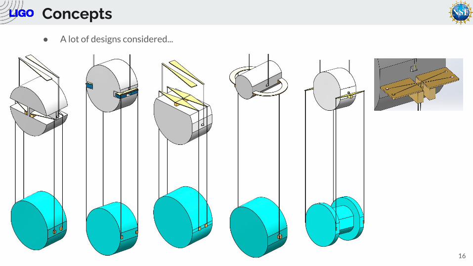
● A lot of designs considered...
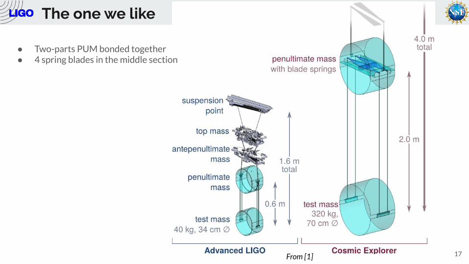
The one we like
17From [1]
● Two-parts PUM bonded together● 4 spring blades in the middle section
Conclusion
18
● Proposed design heavily inspired from the Advanced LIGO suspension
● This is just a concept! A lot of elements still need to be studied (upper stages, bonds, blade
clamps, etc.)
● Using silicon put stringent requirements on the suspension design, but might be doable
● More ideas still to be explored (i.e. Euler springs [18] with MIT/UCLouvain)
Thank you
References[1] Hall, Evan D., et al. "Gravitational-wave physics with Cosmic Explorer: limits to low-frequency sensitivity." arXiv preprint arXiv:2012.03608 (2020).
[2] J. F. Nye, Physical Properties of Crystals: Their Representation by Tensors and Matrices. Oxford, U.K.: Oxford Univ. Press, 1985
[3] M. A. Hopcroft, W. D. Nix and T. W. Kenny, "What is the Young's Modulus of Silicon?," in Journal of Microelectromechanical Systems, vol. 19, no. 2, pp. 229-238, April 2010.
[4] Bourgeois, C., et al. "Design of resonators for the determination of the temperature coefficients of elastic constants of monocrystalline silicon." Proceedings of International Frequency Control Symposium. IEEE, 1997.
[5] Lyon, K. G., et al. "Linear thermal expansion measurements on silicon from 6 to 340 K." Journal of Applied Physics 48.3 (1977): 865-868.
[6] Roundy, David, and Marvin L. Cohen. "Ideal strength of diamond, Si, and Ge." Physical Review B 64.21 (2001): 212103.
[7] Pokluda, J., et al. "Calculations of theoretical strength: State of the art and history." Journal of computer-aided materials design 11.1 (2004): 1-28.
[8] Kozhushko, V. V., A. M. Lomonosov, and P. Hess. "Intrinsic strength of silicon crystals in pure-and combined-mode fracture without precrack." Physical review letters 98.19 (2007): 195505.
[9] Lomonosov, A. M., and P. Hess. "Impulsive fracture of silicon by elastic surface pulses with shocks." Physical review letters 89.9 (2002): 095501.
[10] Lehmann, G., et al. "Impulsive fracture of fused quartz and silicon crystals by nonlinear surface acoustic waves." Journal of applied physics 94.5 (2003): 2907-2914.
19
References[11] Lomonosov, A. M., et al. "Laser-generated nonlinear surface wave pulses in silicon crystals." Physical Review B 69.3 (2004): 035314.
[12] Cumming, A. V., et al. "Silicon mirror suspensions for gravitational wave detectors." Classical and Quantum Gravity 31.2 (2013): 025017.
[13] Birney, Ross, et al. "Coatings and surface treatments for enhanced performance suspensions for future gravitational wave detectors." Classical and Quantum Gravity 34.23 (2017): 235012.
[14] Hu, S. M. "Critical stress in silicon brittle fracture, and effect of ion implantation and other surface treatments." Journal of Applied Physics 53.5 (1982): 3576-3580.
[15] Javvaji, Brahmanandam, et al. "Fracture Properties of Graphene‐Coated Silicon for Photovoltaics." Advanced Theory and Simulations 1.12 (2018): 1800097.
[16] Adhikari, Rana X., et al. "A cryogenic silicon interferometer for gravitational-wave detection." Classical and Quantum Gravity 37.16 (2020): 165003.
[17] Lee, Kyung-Ha, et al. "Improved fused silica fibres for the advanced LIGO monolithic suspensions." Classical and Quantum Gravity 36.18 (2019): 185018.
[18] Winterflood, John, Terran Barber, and D. G. Blair. "Using Euler buckling springs for vibration isolation." Classical and Quantum Gravity 19.7 (2002): 1639.
20
Extra-slides
21
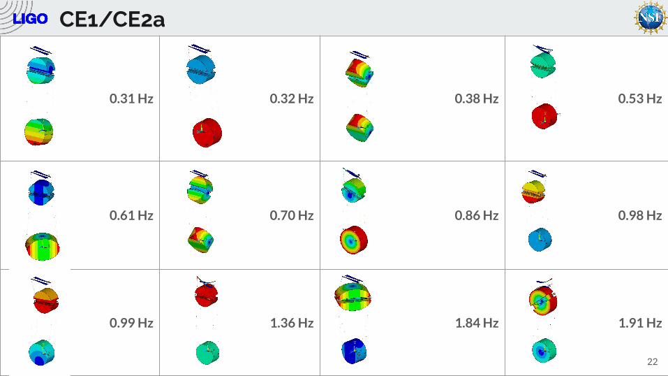
0.31 Hz 0.32 Hz 0.38 Hz 0.53 Hz
0.61 Hz 0.70 Hz 0.86 Hz 0.98 Hz
0.99 Hz 1.36 Hz 1.84 Hz 1.91 Hz
22
CE1/CE2a
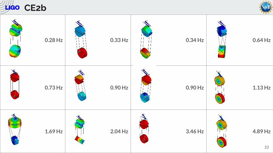
0.28 Hz 0.33 Hz 0.34 Hz 0.64 Hz
0.73 Hz 0.90 Hz 0.90 Hz 1.13 Hz
1.69 Hz 2.04 Hz 3.46 Hz 4.89 Hz
23
CE2b
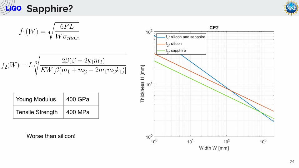
Sapphire?
24
Young Modulus 400 GPa
Tensile Strength 400 MPa
Worse than silicon!
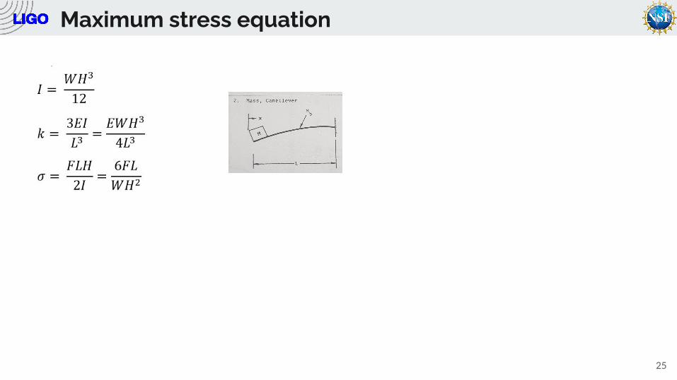
Maximum stress equation
25
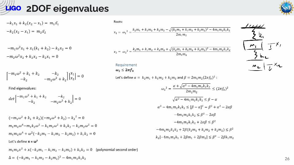
2DOF eigenvalues
26
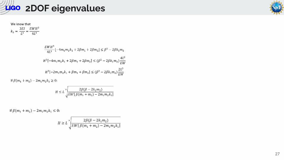
2DOF eigenvalues
27