Supplementary Information Gradient-index meta-surfaces · PDF fileShulin Sun1,2, Qiong He1,...
29
Outline 1. Radiation properties of a surface charge density wave; 2. The mode-expansion theory; 3. The PW-SW conversion efficiency of the 0 k ξ > meta-surface; 4. Time-dependent simulation results of ideal meta-surfaces; 5. Role played by the supper cell of the meta-surface; 6. Pictures and geometrical parameters of the designed/fabricated meta-surfaces; 7. Additional information of the near-field distributions on the 0 1.14k ξ = meta-surface; 8. Intuitive physical picture of the PW-SW conversion process; 9. Operation frequency bandwidth; 10. Making the sub-cells of meta-surfaces more subwavelength; 11. Comparing the gradient meta-surfaces with grating couplers; 12. Guiding the surface waves outside the gradient meta-surfaces; 13. References. Gradient-index meta-surfaces as a bridge linking propagating waves and surface waves SUPPLEMENTARY INFORMATION DOI: 10.1038/NMAT3292 NATURE MATERIALS | www.nature.com/naturematerials 1 © 2012 Macmillan Publishers Limited. All rights reserved.
Transcript of Supplementary Information Gradient-index meta-surfaces · PDF fileShulin Sun1,2, Qiong He1,...
- 1 -
Supplementary Information
Shulin Sun1,2, Qiong He1, Shiyi Xiao1, Qin Xu1 , Xin Li1 and Lei Zhou1
1State Key Laboratory of Surface Physics, Key Laboratory of Micro and Nano Photonic Structures
(Ministry of Education) and Physics Department, Fudan University, Shanghai 200433, China. 2National Center of Theoretical Sciences at Taipei (Physics Division) and Department of Physics,
National Taiwan University, Taipei 10617, Taiwan.
Outline
1. Radiation properties of a surface charge density wave;
2. The mode-expansion theory;
3. The PW-SW conversion efficiency of the 0kξ > meta-surface;
4. Time-dependent simulation results of ideal meta-surfaces;
5. Role played by the supper cell of the meta-surface;
6. Pictures and geometrical parameters of the designed/fabricated
meta-surfaces;
7. Additional information of the near-field distributions on the 01.14kξ =
meta-surface;
8. Intuitive physical picture of the PW-SW conversion process;
9. Operation frequency bandwidth;
10. Making the sub-cells of meta-surfaces more subwavelength;
11. Comparing the gradient meta-surfaces with grating couplers;
12. Guiding the surface waves outside the gradient meta-surfaces;
13. References.
Gradient-index meta-surfaces as a bridge linking propagating waves and surface waves
SUPPLEMENTARY INFORMATIONDOI: 10.1038/NMAT3292
NATURE MATERIALS | www.nature.com/naturematerials 1
© 2012 Macmillan Publishers Limited. All rights reserved.
- 2 -
1. Radiation properties of a surface charge density wave
Consider a surface charge density wave (CDW) with current distribution
0 ˆ( , ) ( )i x i tJ r t J e e z xξ ω δ−= . To obtain the radiation pattern of such a current sheet, we put
it into the frequency-domain Maxwell equations and get
( )20 0( ) ( )k E r i J rμ ω∇×∇× − = , (S1)
where a common time-varying factor i te ω− has been neglected in all physical
quantities, 0 /k cω= , and 0 ˆ( ) ( )i xJ r J e z xξ δ= . Define a dyadic Green's function
( , ; )G r r ω′ [S1] satisfying
20( ) ( , ; ) ( )k G r r r r Iω δ′ ′∇×∇× − = − , (S2)
we find that the E field can be calculated by
0( ) ( , ; ) ( ') 'E r i G r r J r drωμ ω′= ⋅ . (S3)
Straightforward calculations [S1] show that ( ) ( )
2ˆ ˆˆ ˆ( , ; ) [ ( ) ( ) ( ) ( )]
8
ik z r r
z
i eG r r e k e k h k h k dkk
ωπ
′−
′ = +
, (S4)
where 2 2 20zk k k+ = , ( ) | |, 0, ( ) | |, 0z z z zk z k z k z k z= > = − < ; ˆ ˆ ˆ( ) ( ) /y xe k xk yk k= −
and ˆ ˆ( ) ( ) /h k e k k k= ×
are the E field unit vectors for two polarizations. Put Eq. (S4)
into Eq. (S3) and perform the integrations, we finally get
( ) 2 202 2
0 0 0 0 ˆ ˆ( , ) / 2 ( ) i k zi x i tE r t J c k k x z e e eξξ ωμ ξ ξ − −= ⋅ − − + , (S5)
which is just Eq. (1) in the main text. Here the time-varying factor i te ω− has been
added back. H field can be derived from E field as
2 20
00
1 ˆ( , ) / 2 i k zi x i tH r t E J e e e yi
ξξ ω
μ ω− −= ∇× = −
. (S6)
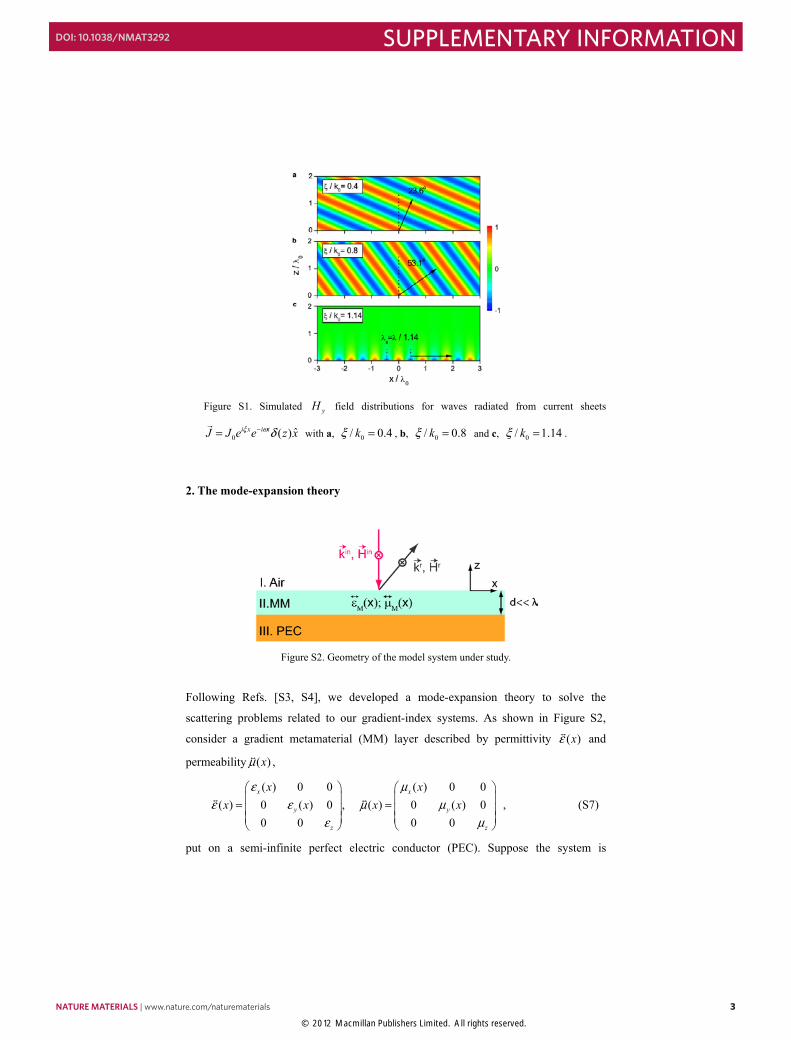
We also employed the finite-element method (FEM) [S2] to directly simulate the
radiation patterns of such current sheets. Figure S1 shows the FEM-simulated radiation
patterns for current sheets with 0 00.4 ,0.8k kξ = and 01.14k , which directly verified
the analytical predictions presented in Eqs. (S5-S6). In particular, in the case of
01.14kξ = , we found that the radiated wave becomes a surface wave with
01.14xk kξ= = .
2 NATURE MATERIALS | www.nature.com/naturematerials
SUPPLEMENTARY INFORMATION DOI: 10.1038/NMAT3292
© 2012 Macmillan Publishers Limited. All rights reserved.
- 3 -
Figure S1. Simulated yH field distributions for waves radiated from current sheets
0 ˆ( )i x i tJ J e e z xξ ω δ−=
with a, 0/ 0.4kξ = , b, 0/ 0.8kξ = and c, 0/ 1.14kξ = .
2. The mode-expansion theory
Figure S2. Geometry of the model system under study.
Following Refs. [S3, S4], we developed a mode-expansion theory to solve the
scattering problems related to our gradient-index systems. As shown in Figure S2,
consider a gradient metamaterial (MM) layer described by permittivity ( )xε and
permeability ( )xμ ,
( ) 0 0 ( ) 0 0
( ) 0 ( ) 0 , ( ) 0 ( ) 00 0 0 0
x x
y y
z z
x xx x x x
ε με ε μ μ
ε μ
= =
, (S7)
put on a semi-infinite perfect electric conductor (PEC). Suppose the system is
NATURE MATERIALS | www.nature.com/naturematerials 3
SUPPLEMENTARY INFORMATIONDOI: 10.1038/NMAT3292
© 2012 Macmillan Publishers Limited. All rights reserved.
- 4 -
illuminated by a transverse-magnetic (TM) plane wave with field given by 0 0
0 0
(in )
00(in )
00 0
ˆ( , )
ˆ ˆ( , )
x z
x z
i k x k z t
i k x k z t xz
H r t e y
kkE r t Z e x zk k
ω
ω
− −
− −
=
= − +
, (S8)
where 0 0 0/Z μ ε= is the vacuum impedance. The field distribution in region I
( 0z > ) can generally be written as I in r
I in r
( )
( )
xx
xx
k xk
k xk
H H H k
E E E k
ρ
ρ
= +
= +
(S9)
in which xkρ are the expansion coefficients to be determined, and
r r{ ( ), ( )}x xE k H k
denotes the reflected plane wave (in TM polarization) with a parallel
wave-vector ˆxk k x=
, which can be obtained by replacing 0 0,x zk k in Eq. (S8) by
2 20,x z xk k k k− = − − , respectively.
We now solve the Maxwell equations to obtain the eigenmodes in region II
( 0d z− < < ) which is occupied by the gradient MM. Only three field components (i.e.,
, ,y x zH E E ) are nonzero in this region, and they satisfy
0
0
0
( )
( )
( )
yx x
yz z
x zy y
Hi x E
zH
i x Ex
E E i x Hz x
ωε ε
ωε ε
ωμ μ
∂= ∂
∂ = − ∂∂ ∂ − = ∂ ∂
. (S10)
Therefore, we find from Eq. (S10) that the yH field satisfies
2202
1( ) ( ) ( ) 0( )x x y y
z
x k x x Hz x x x
ε ε με
∂ ∂ ∂+ + = ∂ ∂ ∂ . (S11)
Since the MM is homogeneous along z direction, yH field can be decoupled as:
( ; , ) ( ; ) , 0ziq zy z z zH q x z G q x e q±± = > (S15)
with ( ; )zG q x being the solutions of the following equation
2 20
1( ) ( ) ( ) ( , ) 0( )x x y z z
z
x k x x q G q xx x x
ε ε με
∂ ∂ + − = ∂ ∂ (S13)
4 NATURE MATERIALS | www.nature.com/naturematerials
SUPPLEMENTARY INFORMATION DOI: 10.1038/NMAT3292
© 2012 Macmillan Publishers Limited. All rights reserved.
- 5 -
To avoid using and ε μ values which are impossible to realize in practice, we often
introduce super cells with periodicity L in designing the true systems, especially for the
[ ]., ( )const xε μ= model (see Figure 1e in the main text). We proved in Section 4 of
this Supplementary Information that Bragg scatterings introduced by the super cells do
not play crucial roles in creating the discussed phenomena. With super cells introduced,
( ; )zG q x can be obtained by numerically solving Eq. (S13) under a super-cell periodic
condition ( ; 0) ( ; )z zG q x G q x L= = = . yH in region II can then be written as
( , ) ( ) ( ; ) ( ) ( ; )z z
z
iq z iq zIIy z z z z
qH x z C q G q x e C q G q x e−+ − = + , (S14)
where { }( ), ( )z zC q C q+ − are another set of expansion coefficients to be determined. E
field components can be easily derived with Eq. (S15). For example,
0
1( , ) ( ) ( ; ) ( ) ( ; )( )
z z
z
iq z iq zIIx z z z z z
qx
E x z q C q G q x e C q G q x exωε ε
−+ − = − . (S15)
All unknown expansion coefficients {xkρ , ( ), ( )z zC q C q+ − } can be determined by
matching the boundary conditions. At the air/ MM interface (i.e., 0z = ), jointing the
tangential electromagnetic (EM) fields yield that 0
00
0 0 0
( , ) ( ) ( )
( , ) ( ) ( )( )
x x
xx z
x x
xx z
ik x ik xk z z z
k q
ik x ik xz z zk z z z
k q x
e e G q x C q C q
k k qe e G q x C q C qk k k x
ρ
ρε
+ −
+ −
+ = + − = − −
. (S16)
At the MM/PEC interface (i.e., z d= − ), we have zero tangential E field, so that
( ) ( ) 0z ziq d iq dz zC q e C q e−+ −− = . (S17)
Put Eq. (S17) to Eq. (S16) and utilize the orthogonal relation: 0 '
0 '( )
,0
1x x
x x
L i k k xk k
e dxL
δ− = ,
we get
0
0
,
,0
( ) ( , )
( ) ( , )
xx xz
xx xz
k z z xk kq
zk z z xzk k
q
C q S q k
k C q S q kk
δ ρ
δ ρ
+
+
+ = − =
, (S18)
with
NATURE MATERIALS | www.nature.com/naturematerials 5
SUPPLEMENTARY INFORMATIONDOI: 10.1038/NMAT3292
© 2012 Macmillan Publishers Limited. All rights reserved.
- 6 -
2
0
200
1( , ) (1 ) ( ; )
1( , ) (1 ) ( , )( )
xz
xz
L ik xi q dz x z
L ik xi q dzz x z
x z
S q k e G q x e dxL
qS q k e G q x e dxL x kε
−−
−−
= + = − −
. (S19)
Therefore, given the material properties [ ( ), ( ),x x dε μ ] of the MM layer, all
coefficients {i.e.,xkρ , ( ), ( )z zC q C q+ − } can thus be determined by solving the coupled
linear equations (S18). In the case that the system is homogeneous so that the parallel k
vector conserves at the interface, we have 0,x x xk k k
ρ δ= . Based on Eq. (S9), we can
easily verify that the mode xk inside the diffraction beam carries an energy flux
2 2 2ˆ ˆˆ| | | | cos | | sinx x x xk k k kk kS k z xρ ρ θ ρ θ= = +
, normalized against that of a normally
incident wave. Therefore, 2| |xkρ provides the information on the energy coupled
from the input beam to the mode labeled by xk .
In Figure 1d & 1f of the main text, one may easily identify that 2| | 1xk ξρ = > for
the meta-surfaces with different ξ . It is surprising at first sight since the energy flux
of this mode is larger than 1 (that of the input wave). However, realizing that the
xk ξ= mode travels along an off-normal direction (non-specular reflection), we
understand the beam width of the reflected wave is reduced by a factor of
( )20cos 1 /r kθ ξ= − . Therefore, integrating the energy flux over the reflected
beam-width, one may easily verify 2| | cos 1xk rξρ θ= ⋅ → for most cases, indicating that
almost all incoming energies are converted to these non-specular reflected modes after
reflections by the gradient-index meta-surfaces.
However, in the case of 00.8kξ = meta-surface constructed based on the
[ 1, ( )]M xε μ= model, we found that 2| | cos 0.918xk rξρ θ= ⋅ and a small peak appears
at 00.8xk k= − (the green line in Figure 1f), which can be attributed to the Bragg
scattering effect (noting that the system must be periodic). However, such unwanted
effects will be significantly reduced if we decrease the thickness d of the gradient MM
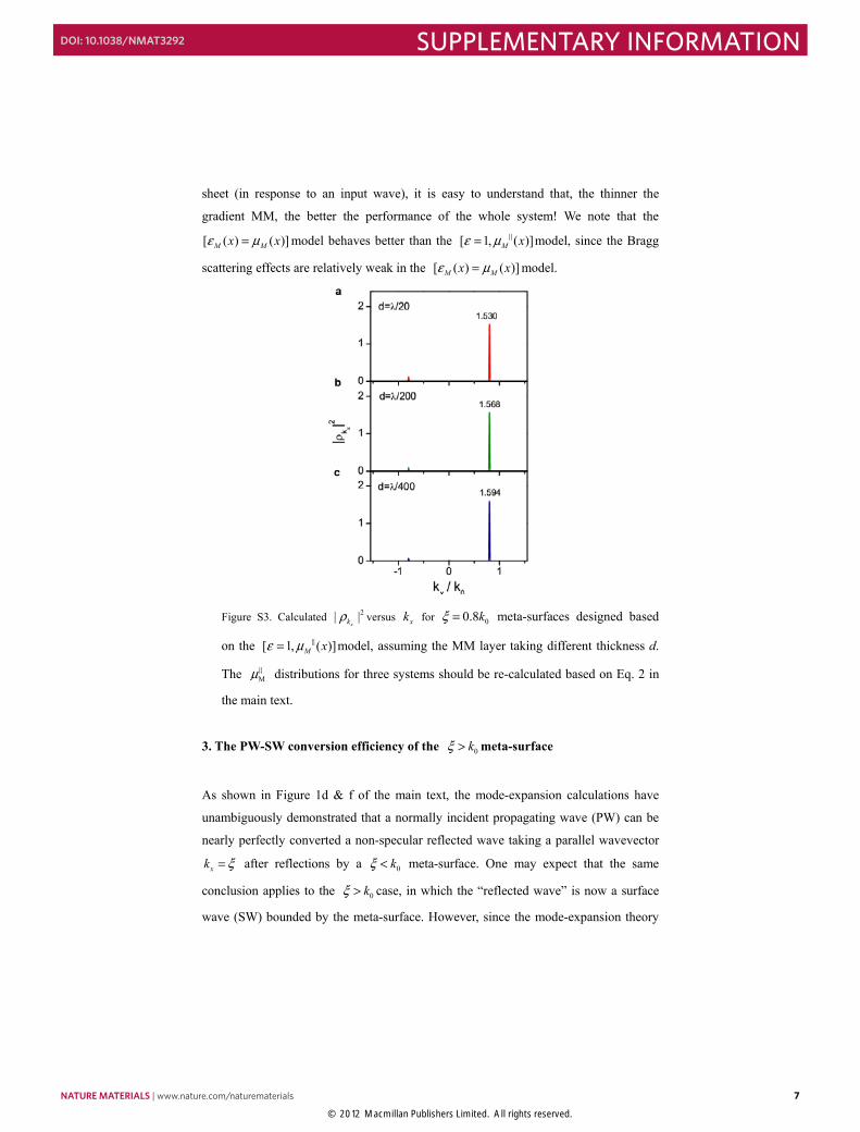
layer. As shown in Figure S3, when d is decreased from / 20λ to / 400λ , we find
that the main peak at xk ξ= is obviously enhanced and the small peak at xk ξ= −
(due to Bragg scatterings) is significantly reduced. The physics is quite simple. Noting
that the model system is designed to approximately represent an infinite-thin current
6 NATURE MATERIALS | www.nature.com/naturematerials
SUPPLEMENTARY INFORMATION DOI: 10.1038/NMAT3292
© 2012 Macmillan Publishers Limited. All rights reserved.
- 7 -
sheet (in response to an input wave), it is easy to understand that, the thinner the
gradient MM, the better the performance of the whole system! We note that the
[ ( ) ( )]M Mx xε μ= model behaves better than the [ 1, ( )]M xε μ= model, since the Bragg
scattering effects are relatively weak in the [ ( ) ( )]M Mx xε μ= model.
Figure S3. Calculated 2| |xkρ versus xk for 00.8kξ = meta-surfaces designed based
on the [ 1, ( )]M xε μ= model, assuming the MM layer taking different thickness d.
The Mμ distributions for three systems should be re-calculated based on Eq. 2 in
the main text.
3. The PW-SW conversion efficiency of the 0kξ > meta-surface
As shown in Figure 1d & f of the main text, the mode-expansion calculations have
unambiguously demonstrated that a normally incident propagating wave (PW) can be
nearly perfectly converted a non-specular reflected wave taking a parallel wavevector
xk ξ= after reflections by a 0kξ < meta-surface. One may expect that the same
conclusion applies to the 0kξ > case, in which the “reflected wave” is now a surface
wave (SW) bounded by the meta-surface. However, since the mode-expansion theory
NATURE MATERIALS | www.nature.com/naturematerials 7
SUPPLEMENTARY INFORMATIONDOI: 10.1038/NMAT3292
© 2012 Macmillan Publishers Limited. All rights reserved.
- 8 -
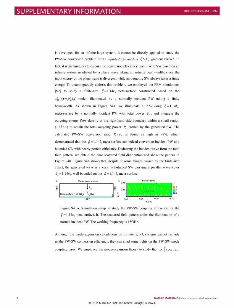
is developed for an infinite-large system, it cannot be directly applied to study the
PW-SW conversion problem for an infinite-large lossless 0kξ > gradient surface. In
fact, it is meaningless to discuss the conversion efficiency from PW to SW based on an
infinite system irradiated by a plane wave taking an infinite beam-width, since the
input energy of the plane wave is divergent while an outgoing SW always takes a finite
energy. To unambiguously address this problem, we employed the FEM simulations
[S2] to study a finite-size 01.14kξ = meta-surface constructed based on the
( ) ( )x xε μ=M M model, illuminated by a normally incident PW taking a finite
beam-width. As shown in Figure S4a, we illuminate a 7.5λ -long 01.14kξ =
meta-surface by a normally incident PW with total power inP , and integrate the
outgoing energy flow density at the right-hand-side boundary within a small region
(~3 / 4λ ) to obtain the total outgoing power sP carried by the generated SW. The
calculated PW-SW conversion ratio /s inP P is found as high as 98%, which
demonstrated that the 01.14kξ = meta-surface can indeed convert an incident PW to a
bounded SW with nearly perfect efficiency. Deducting the incident wave from the total
field pattern, we obtain the pure scattered field distribution and show the pattern in
Figure S4b. Figure S4b shows that, despite of some fringes caused by the finite-size
effect, the generated wave is a very well-shaped SW carrying a parallel wavevector
01.14xk k= , well bounded on the 01.14kξ = meta-surface.
Figure S4. a. Simulation setup to study the PW-SW coupling efficiency for the
01.14kξ = meta-surface. b. The scattered field pattern under the illumination of a
normal incident PW. The working frequency is 15GHz.
Although the mode-expansion calculations on infinite 0kξ > systems cannot provide
us the PW-SW conversion efficiency, they can shed some lights on the PW-SW mode
coupling issue. We employed the mode-expansion theory to study the 2
xkρ spectrum
8 NATURE MATERIALS | www.nature.com/naturematerials
SUPPLEMENTARY INFORMATION DOI: 10.1038/NMAT3292
© 2012 Macmillan Publishers Limited. All rights reserved.
- 9 -
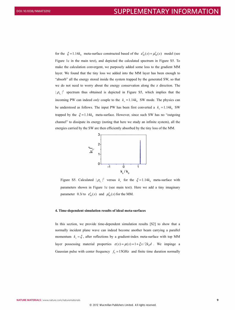
for the 01.14kξ = meta-surface constructed based of the M M( ) ( )x xε μ= model (see
Figure 1c in the main text), and depicted the calculated spectrum in Figure S5. To
make the calculation convergent, we purposely added some loss to the gradient MM
layer. We found that the tiny loss we added into the MM layer has been enough to
“absorb” all the energy stored inside the system trapped by the generated SW, so that
we do not need to worry about the energy conservation along the z direction. The 2| |
xkρ spectrum thus obtained is depicted in Figure S5, which implies that the
incoming PW can indeed only couple to the 01.14xk k= SW mode. The physics can
be understood as follows. The input PW has been first converted a 01.14xk k= SW
trapped by the 01.14kξ = meta-surface. However, since such SW has no “outgoing
channel” to dissipate its energy (noting that here we study an infinite system), all the
energies carried by the SW are then efficiently absorbed by the tiny loss of the MM.
Figure S5. Calculated 2| |xkρ versus xk for the 01.14kξ = meta-surface with
parameters shown in Figure 1c (see main text). Here we add a tiny imaginary
parameter 0.3i to M ( )xε and M ( )xμ for the MM.
4. Time-dependent simulation results of ideal meta-surfaces
In this section, we provide time-dependent simulation results [S2] to show that a
normally incident plane wave can indeed become another beam carrying a parallel
momentum xk ξ= , after reflections by a gradient-index meta-surface with top MM
layer possessing material properties 0( ) ( ) 1 / 2x x x k dε μ ξ= = + . We impinge a
Gaussian pulse with center frequency 0 15GHzf = and finite time duration normally
NATURE MATERIALS | www.nature.com/naturematerials 9
SUPPLEMENTARY INFORMATIONDOI: 10.1038/NMAT3292
© 2012 Macmillan Publishers Limited. All rights reserved.
- 10 -
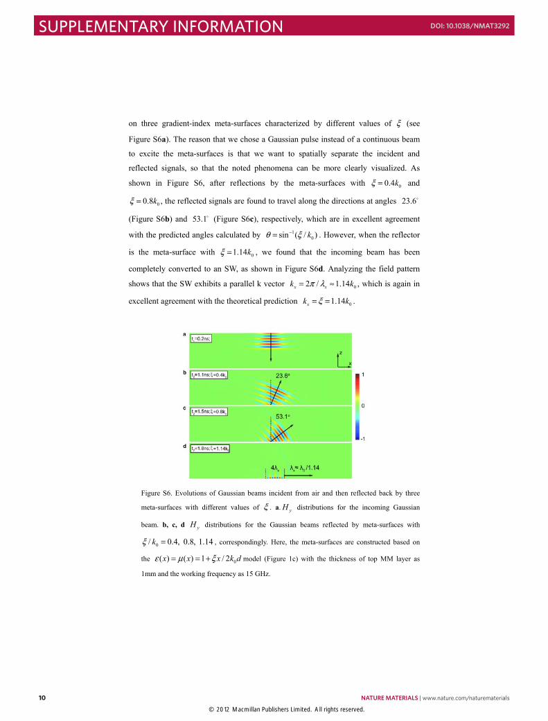
on three gradient-index meta-surfaces characterized by different values of ξ (see
Figure S6a). The reason that we chose a Gaussian pulse instead of a continuous beam
to excite the meta-surfaces is that we want to spatially separate the incident and
reflected signals, so that the noted phenomena can be more clearly visualized. As
shown in Figure S6, after reflections by the meta-surfaces with 00.4kξ = and
00.8kξ = , the reflected signals are found to travel along the directions at angles 23.6
(Figure S6b) and 53.1 (Figure S6c), respectively, which are in excellent agreement
with the predicted angles calculated by 10sin ( / )kθ ξ−= . However, when the reflector
is the meta-surface with 01.14kξ = , we found that the incoming beam has been
completely converted to an SW, as shown in Figure S6d. Analyzing the field pattern
shows that the SW exhibits a parallel k vector 02 / 1.14x xk kπ λ= ≈ , which is again in
excellent agreement with the theoretical prediction 01.14xk kξ= = .
Figure S6. Evolutions of Gaussian beams incident from air and then reflected back by three
meta-surfaces with different values of ξ . a. yH distributions for the incoming Gaussian
beam. b, c, d yH distributions for the Gaussian beams reflected by meta-surfaces with
0/ 0.4, 0.8, 1.14kξ = , correspondingly. Here, the meta-surfaces are constructed based on
the 0( ) ( ) 1 / 2x x x k dε μ ξ= = + model (Figure 1c) with the thickness of top MM layer as
1mm and the working frequency as 15 GHz.
10 NATURE MATERIALS | www.nature.com/naturematerials
SUPPLEMENTARY INFORMATION DOI: 10.1038/NMAT3292
© 2012 Macmillan Publishers Limited. All rights reserved.
- 11 -
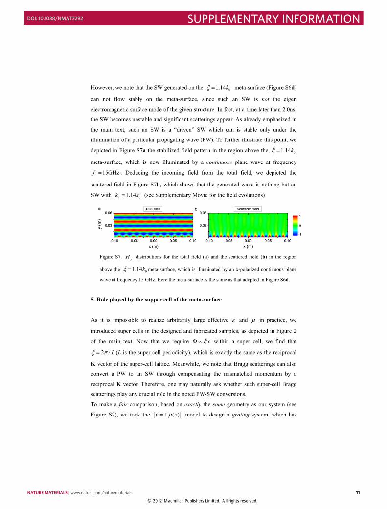
However, we note that the SW generated on the 01.14kξ = meta-surface (Figure S6d)
can not flow stably on the meta-surface, since such an SW is not the eigen
electromagnetic surface mode of the given structure. In fact, at a time later than 2.0ns,
the SW becomes unstable and significant scatterings appear. As already emphasized in
the main text, such an SW is a “driven” SW which can is stable only under the
illumination of a particular propagating wave (PW). To further illustrate this point, we
depicted in Figure S7a the stabilized field pattern in the region above the 01.14kξ =
meta-surface, which is now illuminated by a continuous plane wave at frequency
0 15GHzf = . Deducing the incoming field from the total field, we depicted the
scattered field in Figure S7b, which shows that the generated wave is nothing but an
SW with 01.14xk k= (see Supplementary Movie for the field evolutions)
Figure S7. yH distributions for the total field (a) and the scattered field (b) in the region
above the 01.14kξ = meta-surface, which is illuminated by an x-polarized continuous plane
wave at frequency 15 GHz. Here the meta-surface is the same as that adopted in Figure S6d.
5. Role played by the supper cell of the meta-surface
As it is impossible to realize arbitrarily large effective ε and μ in practice, we
introduced super cells in the designed and fabricated samples, as depicted in Figure 2
of the main text. Now that we require xξΦ ∝ within a super cell, we find that
2 / Lξ π= (L is the super-cell periodicity), which is exactly the same as the reciprocal
K vector of the super-cell lattice. Meanwhile, we note that Bragg scatterings can also
convert a PW to an SW through compensating the mismatched momentum by a
reciprocal K vector. Therefore, one may naturally ask whether such super-cell Bragg
scatterings play any crucial role in the noted PW-SW conversions.
To make a fair comparison, based on exactly the same geometry as our system (see
Figure S2), we took the [ 1, ( )]xε μ= model to design a grating system, which has
NATURE MATERIALS | www.nature.com/naturematerials 11
SUPPLEMENTARY INFORMATIONDOI: 10.1038/NMAT3292
© 2012 Macmillan Publishers Limited. All rights reserved.
- 12 -
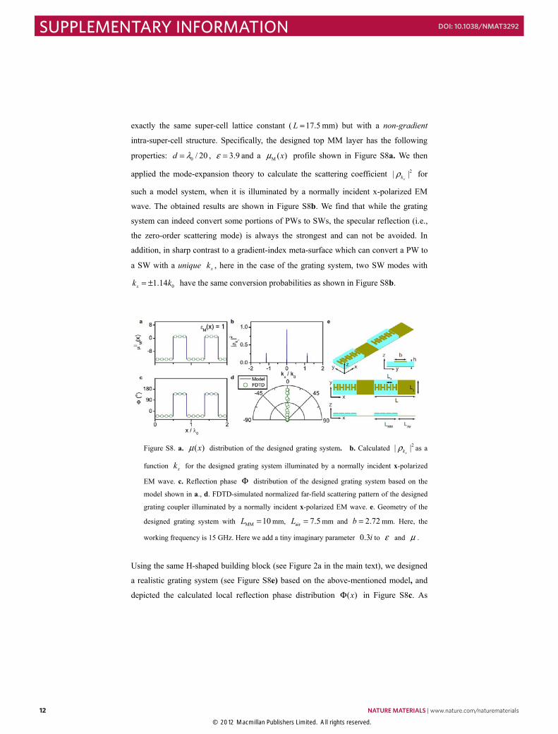
exactly the same super-cell lattice constant ( 17.5L = mm) but with a non-gradient
intra-super-cell structure. Specifically, the designed top MM layer has the following
properties: 0 / 20d λ= , 3.9ε = and a M ( )xμ profile shown in Figure S8a. We then
applied the mode-expansion theory to calculate the scattering coefficient 2| |xkρ for
such a model system, when it is illuminated by a normally incident x-polarized EM
wave. The obtained results are shown in Figure S8b. We find that while the grating
system can indeed convert some portions of PWs to SWs, the specular reflection (i.e.,
the zero-order scattering mode) is always the strongest and can not be avoided. In
addition, in sharp contrast to a gradient-index meta-surface which can convert a PW to
a SW with a unique xk , here in the case of the grating system, two SW modes with
01.14xk k= ± have the same conversion probabilities as shown in Figure S8b.
Figure S8. a. ( )xμ distribution of the designed grating system. b. Calculated 2| |xkρ as a
function xk for the designed grating system illuminated by a normally incident x-polarized
EM wave. c. Reflection phase Φ distribution of the designed grating system based on the
model shown in a., d. FDTD-simulated normalized far-field scattering pattern of the designed
grating coupler illuminated by a normally incident x-polarized EM wave. e. Geometry of the
designed grating system with MM 10L = mm, air 7.5L = mm and 2.72b = mm. Here, the
working frequency is 15 GHz. Here we add a tiny imaginary parameter 0.3i to ε and μ .
Using the same H-shaped building block (see Figure 2a in the main text), we designed
a realistic grating system (see Figure S8e) based on the above-mentioned model, and
depicted the calculated local reflection phase distribution ( )xΦ in Figure S8c. As
12 NATURE MATERIALS | www.nature.com/naturematerials
SUPPLEMENTARY INFORMATION DOI: 10.1038/NMAT3292
© 2012 Macmillan Publishers Limited. All rights reserved.
- 13 -
expected, compared with the 01.14kξ = sample adopted in our experiment (Figure
2g), the present sample does not show a gradient ( )xΦ distribution but it does have
the same super-cell periodicity. Illuminated by a normally incident x-polarized plane
wave at frequency 15 GHz, we performed FDTD simulations [S5] to calculate the
far-field scattering pattern and showed the result in Figure S8d. Clearly, for such a
grating system, the zero-order scattering (the specular reflection) can not be avoided.
All these features are in sharp contrast with the results obtained with our
gradient-index meta-surface with the same super-cell periodicity, as shown in the main
text. Therefore, this proved that the super-cell periodicity is not the crucial factor
responsible for the noted perfect PW-SW conversion.
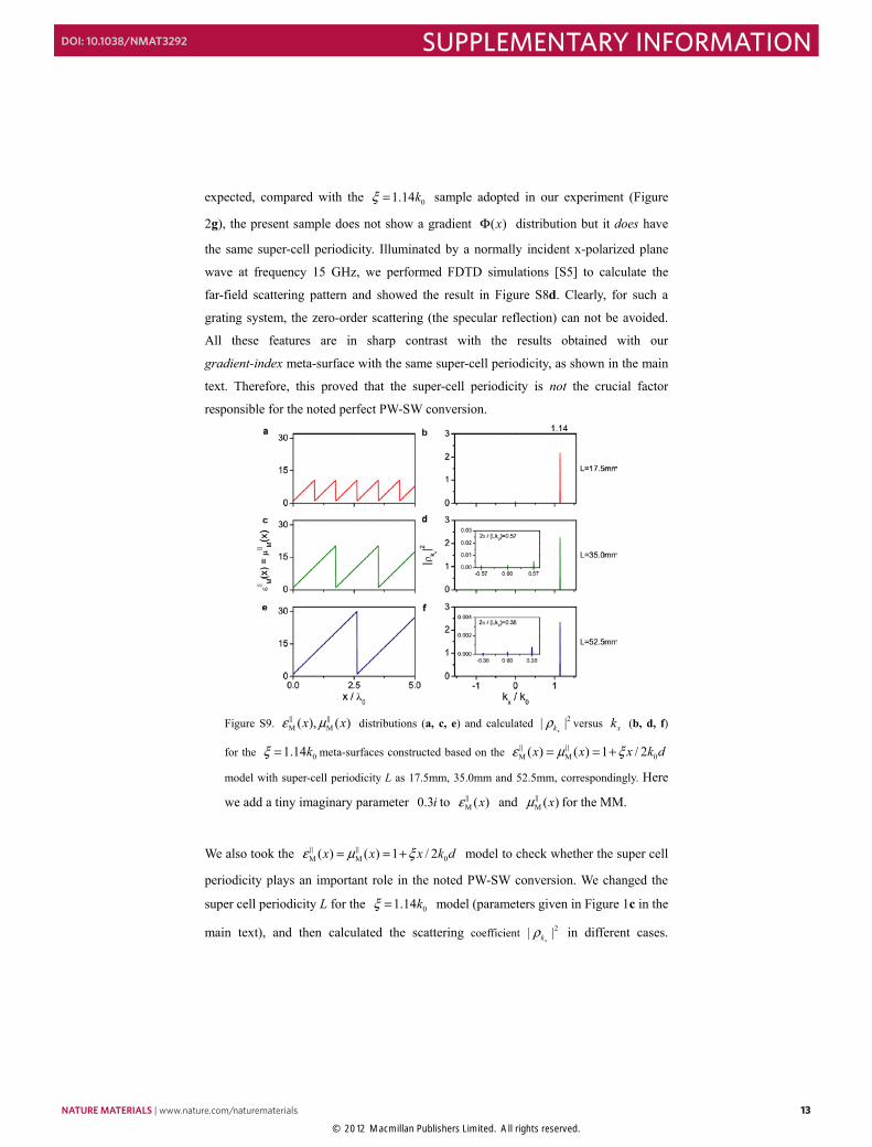
Figure S9. M M( ), ( )x xε μ distributions (a, c, e) and calculated 2| |xkρ versus xk (b, d, f)
for the 01.14kξ = meta-surfaces constructed based on the M M 0( ) ( ) 1 / 2x x x k dε μ ξ= = +
model with super-cell periodicity L as 17.5mm, 35.0mm and 52.5mm, correspondingly. Here
we add a tiny imaginary parameter 0.3i to M ( )xε and M ( )xμ for the MM.
We also took the M M 0( ) ( ) 1 / 2x x x k dε μ ξ= = + model to check whether the super cell
periodicity plays an important role in the noted PW-SW conversion. We changed the
super cell periodicity L for the 01.14kξ = model (parameters given in Figure 1c in the
main text), and then calculated the scattering coefficient 2| |xkρ in different cases.
NATURE MATERIALS | www.nature.com/naturematerials 13
SUPPLEMENTARY INFORMATIONDOI: 10.1038/NMAT3292
© 2012 Macmillan Publishers Limited. All rights reserved.
- 14 -
Figure S9 shows the distributions of MM properties for three 01.14kξ =
meta-surfaces with different super-cell periodicities (a, c, e) and their corresponding
scattering coefficients 2
xkρ as functions of (b, d, f). Comparison shows that varying
the super-cell periodicity L has no significant effect on the calculated 2| |xkρ , so that
Bragg scatterings do not play an important role in the PW-SW conversion phenomena
discussed in the present paper.
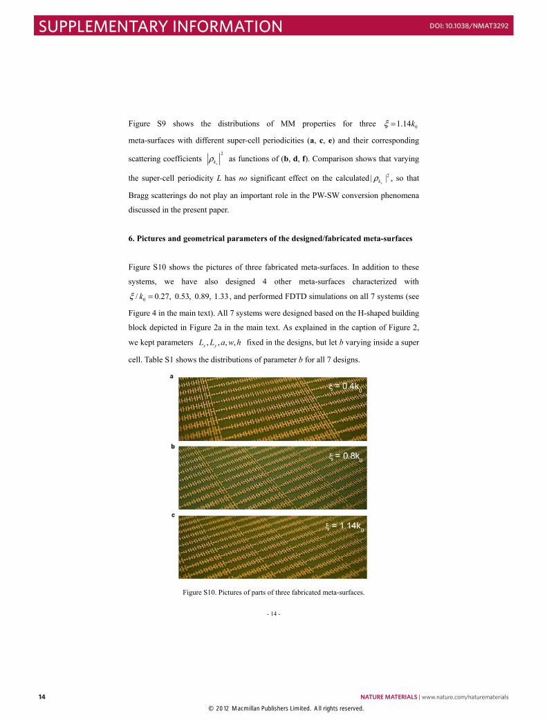
6. Pictures and geometrical parameters of the designed/fabricated meta-surfaces
Figure S10 shows the pictures of three fabricated meta-surfaces. In addition to these
systems, we have also designed 4 other meta-surfaces characterized with
0/ 0.27, 0.53, 0.89, 1.33kξ = , and performed FDTD simulations on all 7 systems (see
Figure 4 in the main text). All 7 systems were designed based on the H-shaped building
block depicted in Figure 2a in the main text. As explained in the caption of Figure 2,
we kept parameters , , , ,x yL L a w h fixed in the designs, but let b varying inside a super
cell. Table S1 shows the distributions of parameter b for all 7 designs.
Figure S10. Pictures of parts of three fabricated meta-surfaces.
14 NATURE MATERIALS | www.nature.com/naturematerials
SUPPLEMENTARY INFORMATION DOI: 10.1038/NMAT3292
© 2012 Macmillan Publishers Limited. All rights reserved.
- 15 -
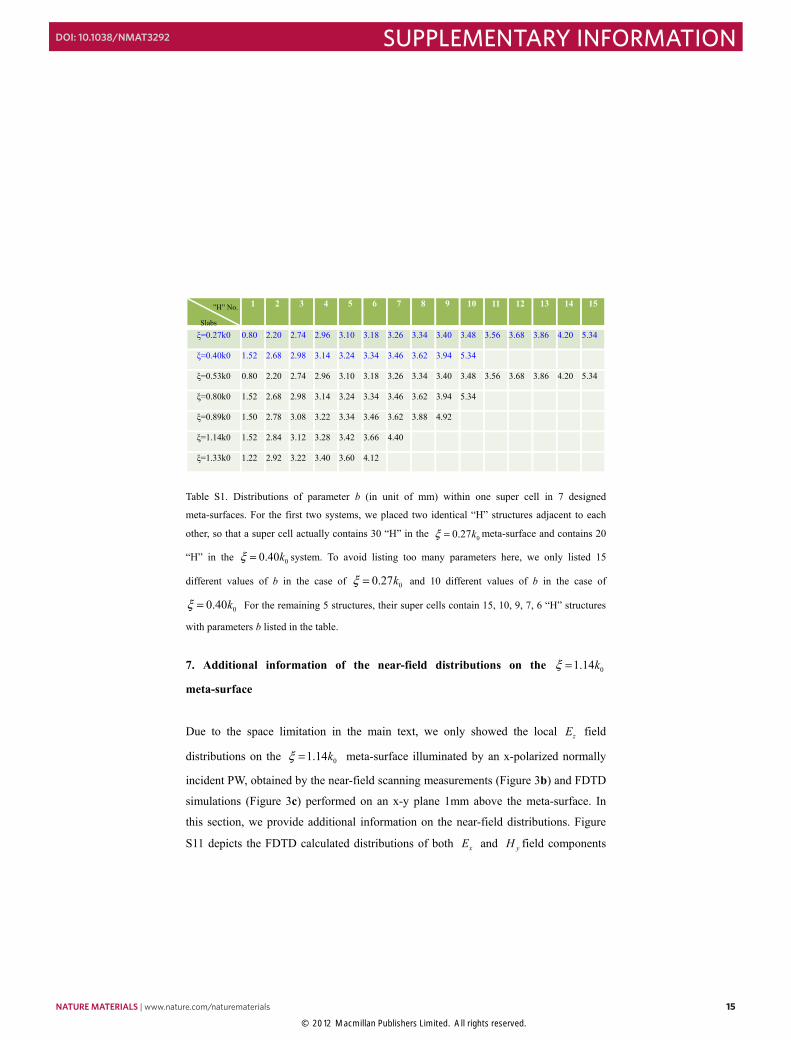
1 2 3 4 5 6 7 8 9 10 11 12 13 14 15
ξ=0.27k0 0.80 2.20 2.74 2.96 3.10 3.18 3.26 3.34 3.40 3.48 3.56 3.68 3.86 4.20 5.34
ξ=0.40k0 1.52 2.68 2.98 3.14 3.24 3.34 3.46 3.62 3.94 5.34
ξ=0.53k0 0.80 2.20 2.74 2.96 3.10 3.18 3.26 3.34 3.40 3.48 3.56 3.68 3.86 4.20 5.34
ξ=0.80k0 1.52 2.68 2.98 3.14 3.24 3.34 3.46 3.62 3.94 5.34
ξ=0.89k0 1.50 2.78 3.08 3.22 3.34 3.46 3.62 3.88 4.92
ξ=1.14k0 1.52 2.84 3.12 3.28 3.42 3.66 4.40
ξ=1.33k0 1.22 2.92 3.22 3.40 3.60 4.12
Table S1. Distributions of parameter b (in unit of mm) within one super cell in 7 designed
meta-surfaces. For the first two systems, we placed two identical “H” structures adjacent to each
other, so that a super cell actually contains 30 “H” in the 00.27kξ = meta-surface and contains 20
“H” in the 00.40kξ = system. To avoid listing too many parameters here, we only listed 15
different values of b in the case of 00.27kξ = and 10 different values of b in the case of
00.40kξ = For the remaining 5 structures, their super cells contain 15, 10, 9, 7, 6 “H” structures
with parameters b listed in the table.
7. Additional information of the near-field distributions on the 01.14kξ =
meta-surface
Due to the space limitation in the main text, we only showed the local zE field
distributions on the 01.14kξ = meta-surface illuminated by an x-polarized normally
incident PW, obtained by the near-field scanning measurements (Figure 3b) and FDTD
simulations (Figure 3c) performed on an x-y plane 1mm above the meta-surface. In
this section, we provide additional information on the near-field distributions. Figure
S11 depicts the FDTD calculated distributions of both xE and yH field components
”H” No.
Slabs
NATURE MATERIALS | www.nature.com/naturematerials 15
SUPPLEMENTARY INFORMATIONDOI: 10.1038/NMAT3292
© 2012 Macmillan Publishers Limited. All rights reserved.
- 16 -
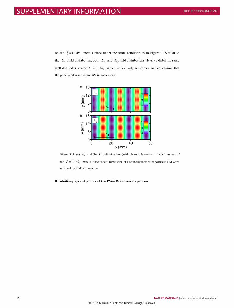
on the 01.14kξ = meta-surface under the same condition as in Figure 3. Similar to
the zE field distribution, both xE and yH field distributions clearly exhibit the same
well-defined k vector 01.14xk k≈ , which collectively reinforced our conclusion that
the generated wave is an SW in such a case.
Figure S11. (a) xE and (b) yH distributions (with phase information included) on part of
the 01.14kξ = meta-surface under illumination of a normally incident x-polarized EM wave
obtained by FDTD simulation.
8. Intuitive physical picture of the PW-SW conversion process
16 NATURE MATERIALS | www.nature.com/naturematerials
SUPPLEMENTARY INFORMATION DOI: 10.1038/NMAT3292
© 2012 Macmillan Publishers Limited. All rights reserved.
- 17 -
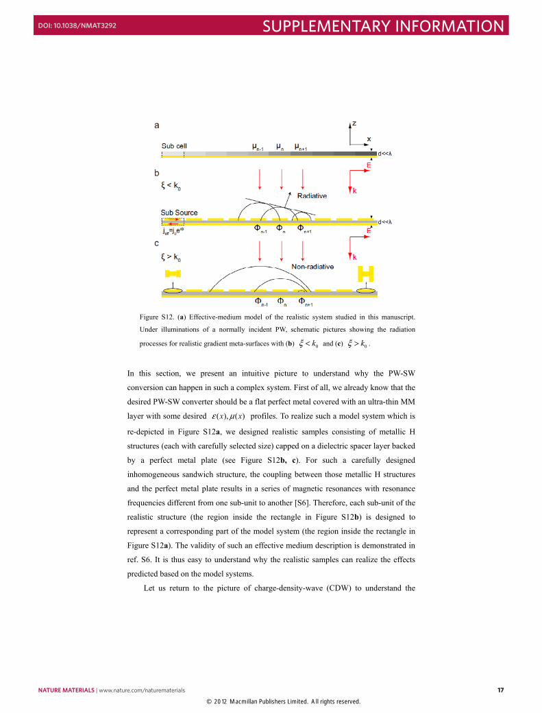
Figure S12. (a) Effective-medium model of the realistic system studied in this manuscript.
Under illuminations of a normally incident PW, schematic pictures showing the radiation
processes for realistic gradient meta-surfaces with (b) 0kξ < and (c) 0kξ > .
In this section, we present an intuitive picture to understand why the PW-SW
conversion can happen in such a complex system. First of all, we already know that the
desired PW-SW converter should be a flat perfect metal covered with an ultra-thin MM
layer with some desired ( ), ( )x xε μ profiles. To realize such a model system which is
re-depicted in Figure S12a, we designed realistic samples consisting of metallic H
structures (each with carefully selected size) capped on a dielectric spacer layer backed
by a perfect metal plate (see Figure S12b, c). For such a carefully designed
inhomogeneous sandwich structure, the coupling between those metallic H structures
and the perfect metal plate results in a series of magnetic resonances with resonance
frequencies different from one sub-unit to another [S6]. Therefore, each sub-unit of the
realistic structure (the region inside the rectangle in Figure S12b) is designed to
represent a corresponding part of the model system (the region inside the rectangle in
Figure S12a). The validity of such an effective medium description is demonstrated in
ref. S6. It is thus easy to understand why the realistic samples can realize the effects
predicted based on the model systems.
Let us return to the picture of charge-density-wave (CDW) to understand the
NATURE MATERIALS | www.nature.com/naturematerials 17
SUPPLEMENTARY INFORMATIONDOI: 10.1038/NMAT3292
© 2012 Macmillan Publishers Limited. All rights reserved.
- 18 -
realistic scattering processes. As shown in Figure S12b, under the illumination of an
x-polarized incident plane wave, electric currents will be induced inside each sub unit.
Although the distributions of induced currents are very complex, recognizing the fact
that the size of each sub cell is deeply wavelength ( / 20λ in thickness and / 8λ in
lateral dimension), we can average the complex currents inside each sub unit (the
region inside rectangle) to obtain an effective current. Since there is a perfect metal
plate on the back, the entire system is totally reflective on every local point. Therefore,
the amplitude of the effective current related to each sub-unit should be the same
although the phase of current varies from one sub-unit to another. The scattering field
is obtained by summing up all the waves radiated from these effective current sources
which are described by (i)eff 0ˆ~ iij xj e Φ
, and we have carefully designed the system to let
i ixξΦ ∝ where ix is the central location of the ith sub-unit. Therefore, what we
have realized on the meta-surface is just an effective CDW in a discrete version! In the
0kξ < case as shown in Figure S12b, the interference among the waves radiated from
different sub sources result in a beam which leaves the surface at an oblique angle 1
0sin ( / )kξ− . However, when 0kξ > , the interference among those waves can NOT
form a propagating beam, but rather forms a SW trapped on the surface (see Figure
S12c).
9. Operation frequency bandwidth
In the main text, all results depicted in Figs. 2-4 are obtained at a single frequency 15
GHz. However, we will show in the following that there is about 1 GHz operation
bandwidth for the fabricated meta-surfaces. Due to the computation limitation, we
always adopted finite-size samples in our simulations. For the present problems
(including those presented in the main text), we assumed that three designed samples
are 450mm-, 450mm- and 445mm – wide along x direction, and set periodic boundary
conditions along y direction. Set working frequencies at 14.5 GHz and 15.5 GHz, we
experimentally and theoretically studied the far-field scattering patterns of all three
meta-surfaces (as in Figure 2 of the main text) and the local field distributions on the
01.14kξ = meta-surface (as in Figure 3 of the main text), under normally incident
microwave radiations. The results plotted in Figs. S13-S14 unambiguously
18 NATURE MATERIALS | www.nature.com/naturematerials
SUPPLEMENTARY INFORMATION DOI: 10.1038/NMAT3292
© 2012 Macmillan Publishers Limited. All rights reserved.
- 19 -
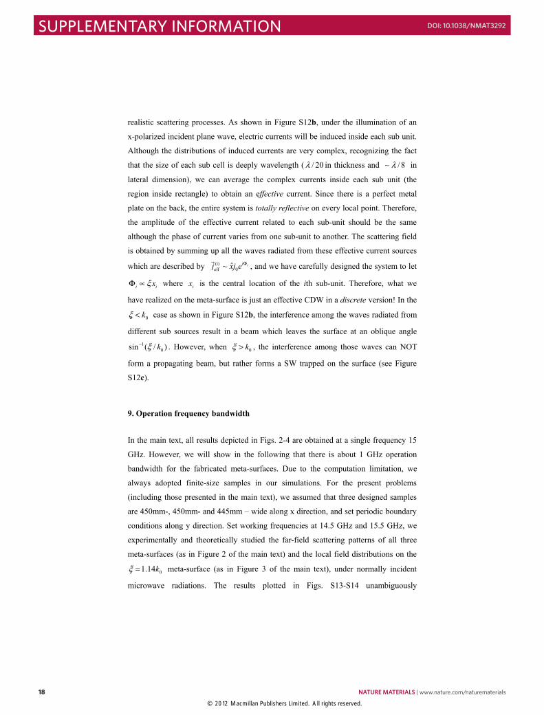
demonstrated that the predicted phenomena (i.e., redirecting the scattered beam to a
different angle, disappearance of far-field scatterings for the 01.14kξ = system, etc. )
well survived for both 14.5 GHz and 15.5 GHz cases, although slight discrepancies do
exist as compared to theoretical predictions, especially in the 14.5 GHz case (see Figs.
S13c and S14a).
Figure S13. Measured and simulated scattering patterns for three fabricated meta-surfaces with
different values of 0/ kξ , under illuminations of normally incident x-polarized microwaves at
frequencies 14.5 GHz and 15.5GHz.
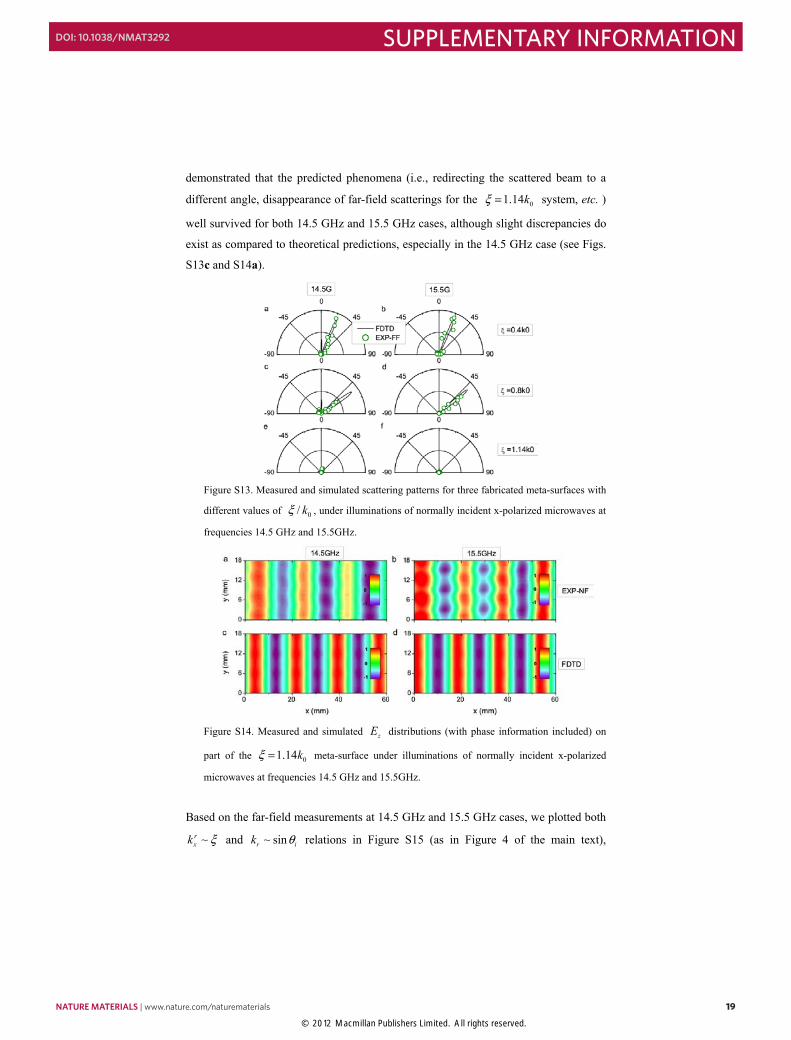
Figure S14. Measured and simulated zE distributions (with phase information included) on
part of the 01.14kξ = meta-surface under illuminations of normally incident x-polarized
microwaves at frequencies 14.5 GHz and 15.5GHz.
Based on the far-field measurements at 14.5 GHz and 15.5 GHz cases, we plotted both
~rxk ξ and ~ sinr ik θ relations in Figure S15 (as in Figure 4 of the main text),
NATURE MATERIALS | www.nature.com/naturematerials 19
SUPPLEMENTARY INFORMATIONDOI: 10.1038/NMAT3292
© 2012 Macmillan Publishers Limited. All rights reserved.
- 20 -
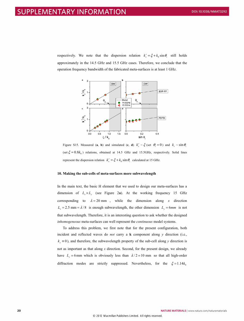
respectively. We note that the dispersion relation 0 sinrx ik kξ θ= + still holds
approximately in the 14.5 GHz and 15.5 GHz cases. Therefore, we conclude that the
operation frequency bandwidth of the fabricated meta-surfaces is at least 1 GHz.
Figure S15. Measured (a, b) and simulated (c, d) ~rxk ξ (set 0iθ = ) and ~ sinr ik θ
(set 00.8kξ = ) relations, obtained at 14.5 GHz and 15.5GHz, respectively. Solid lines
represent the dispersion relation 0 sinrx ik kξ θ= + calculated at 15 GHz.
10. Making the sub-cells of meta-surfaces more subwavelength
In the main text, the basic H element that we used to design our meta-surfaces has a
dimension of x yL L× (see Figure 2a). At the working frequency 15 GHz
corresponding to 20 mmλ = , while the dimension along x direction
2.5 mm / 8xL λ= = is enough subwavelength, the other dimension 6yL mm= is not
that subwavelength. Therefore, it is an interesting question to ask whether the designed
inhomogeneous meta-surfaces can well represent the continuous model systems.
To address this problem, we first note that for the present configuration, both
incident and reflected waves do not carry a k component along y direction (i.e.,
0yk ≡ ), and therefore, the subwavelength property of the sub-cell along y direction is
not as important as that along x direction. Second, for the present design, we already
have 6yL = mm which is obviously less than / 2 10 mmλ = so that all high-order
diffraction modes are strictly suppressed. Nevertheless, for the 01.14kξ =
20 NATURE MATERIALS | www.nature.com/naturematerials
SUPPLEMENTARY INFORMATION DOI: 10.1038/NMAT3292
© 2012 Macmillan Publishers Limited. All rights reserved.
- 21 -
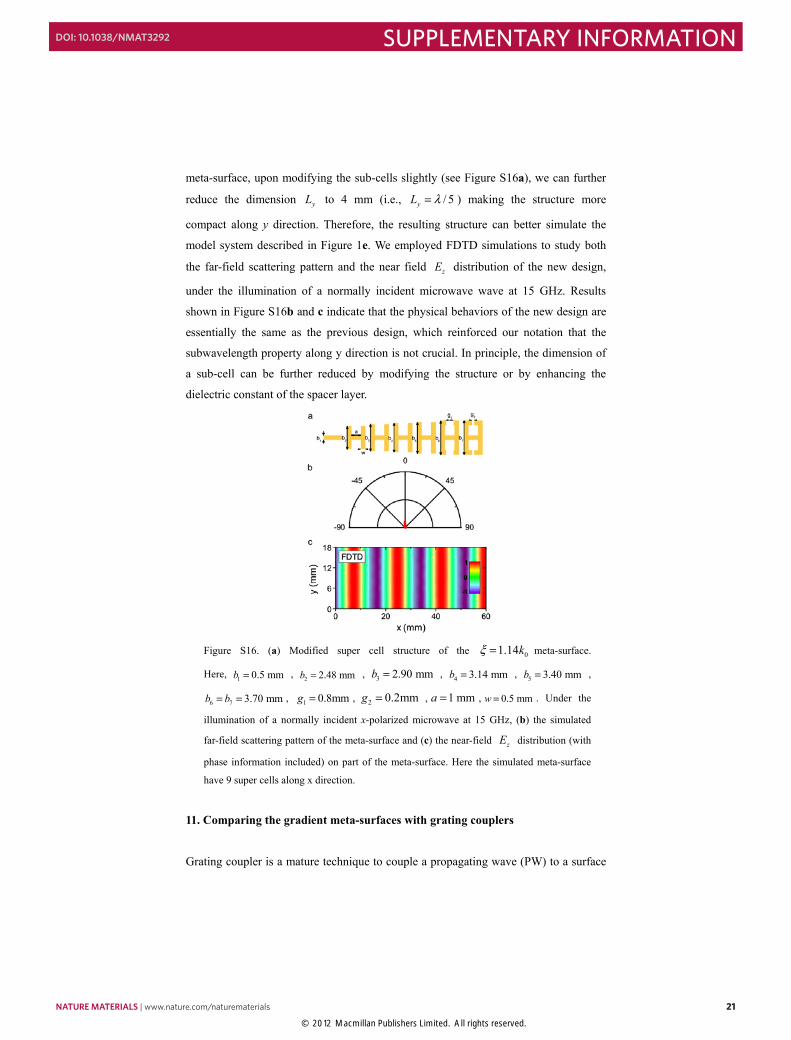
meta-surface, upon modifying the sub-cells slightly (see Figure S16a), we can further
reduce the dimension yL to 4 mm (i.e., / 5yL λ= ) making the structure more
compact along y direction. Therefore, the resulting structure can better simulate the
model system described in Figure 1e. We employed FDTD simulations to study both
the far-field scattering pattern and the near field zE distribution of the new design,
under the illumination of a normally incident microwave wave at 15 GHz. Results
shown in Figure S16b and c indicate that the physical behaviors of the new design are
essentially the same as the previous design, which reinforced our notation that the
subwavelength property along y direction is not crucial. In principle, the dimension of
a sub-cell can be further reduced by modifying the structure or by enhancing the
dielectric constant of the spacer layer.
Figure S16. (a) Modified super cell structure of the 01.14kξ = meta-surface.
Here, 1 0.5 mmb = , 2 2.48 mmb = , 3 2.90 mmb = , 4 3.14 mmb = , 5 3.40 mmb = ,
6 7 3.70 mmb b= = , 1 0.8mmg = , 2 0.2mm g = , 1 mma = , 0.5 mmw = . Under the
illumination of a normally incident x-polarized microwave at 15 GHz, (b) the simulated
far-field scattering pattern of the meta-surface and (c) the near-field zE distribution (with
phase information included) on part of the meta-surface. Here the simulated meta-surface
have 9 super cells along x direction.
11. Comparing the gradient meta-surfaces with grating couplers
Grating coupler is a mature technique to couple a propagating wave (PW) to a surface
NATURE MATERIALS | www.nature.com/naturematerials 21
SUPPLEMENTARY INFORMATIONDOI: 10.1038/NMAT3292
© 2012 Macmillan Publishers Limited. All rights reserved.
- 22 -
plasmon polariton (SPP) or a guided surface wave (SW) [S7]. In the following, we do
not differentiate the SPP or a guided SW since both of them are the eigen surface
modes of a given system. Suppose a system supports well-defined SPP with parallel
wavevector SPPk larger than 0 /k cω= , such SPP can not couple to incident PW
directly since in|| 0k k< . By periodically corrugating the system surface, a PW can
resonantly couple to an SPP when the momentum matching condition in|| SPPk nG k+ =
can be satisfied, in which / aG Pπ= is the reciprocal K-vector with aP being the
grating periodicity and n is an arbitrary integer. Here we consider the one-dimensional
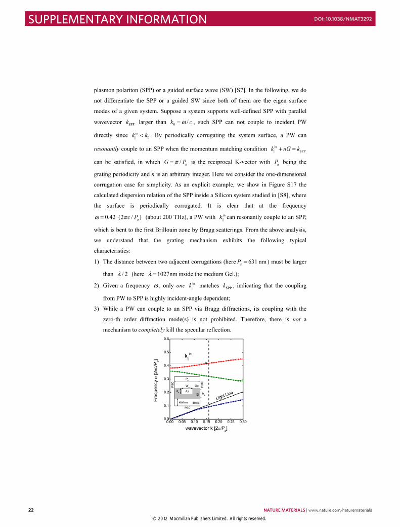
corrugation case for simplicity. As an explicit example, we show in Figure S17 the
calculated dispersion relation of the SPP inside a Silicon system studied in [S8], where
the surface is periodically corrugated. It is clear that at the frequency
0.42 (2 / )ac Pω π= ⋅ (about 200 THz), a PW with in||k can resonantly couple to an SPP,
which is bent to the first Brillouin zone by Bragg scatterings. From the above analysis,
we understand that the grating mechanism exhibits the following typical
characteristics:
1) The distance between two adjacent corrugations (here 631 nmaP = ) must be larger
than / 2λ (here 1027nmλ = inside the medium Gel.);
2) Given a frequency ω , only one in||k matches SPPk , indicating that the coupling
from PW to SPP is highly incident-angle dependent;
3) While a PW can couple to an SPP via Bragg diffractions, its coupling with the
zero-th order diffraction mode(s) is not prohibited. Therefore, there is not a
mechanism to completely kill the specular reflection.
22 NATURE MATERIALS | www.nature.com/naturematerials
SUPPLEMENTARY INFORMATION DOI: 10.1038/NMAT3292
© 2012 Macmillan Publishers Limited. All rights reserved.
- 23 -
Figure S17. SPP band structure of the studied system. Inset shows the unit cell geometry of the
studied system consisting of a 250nm thick Silicon (n=3.45) layer sandwiched by a Silica
(n=1.45) layer and a Gel (n=1.46) layer. Periodic boundary condition (PBC) is used at the unit
cell boundaries. Here the parameters are ad = 102 nm, aW = 160 nm, ah = 250 nm, and
aP = 631 nm. To make the comparison with our meta-surface meaningful, we put a perfect
metal conductor (PEC) at 1000nm below the system to ensure that there is no transmission
through the device.
The second characteristic makes the device difficult to couple a Gaussian beam (which
does not exhibit a single in||k ) to the SPP. To overcome this inherent difficulty, the
non-uniform grating coupler was proposed [S8], where the strict periodicity of the
surface corrugation was released. By optimizing each corrugation carefully, one would
achieve a design to have the best coupling efficiency with a given Gaussian input beam
[S8]. Obviously, the working principle for such non-uniform grating coupler is
essentially the same as a uniform grating coupler, except that the former device can
have a wider operation angle range compared to the latter.
However, our gradient-index meta-surface exhibits completely different
characteristics in all above aspects. We already mentioned in Sec. 9 that the feature size
of our “cell” is deeply subwavelength (i.e., , / 2x yL L λ ), which is in sharp contrast
to the first characteristic of grating couplers. In what follows, we will explicitly
compare the functionalities of our gradient meta-surface (taking the 00.8kξ = system
as an example), uniform and non-uniform grating couplers, in terms of the operation
angle range and specular-reflection suppression (e.g., the last two characteristics). As
an example, we choose the non-uniform grating coupler as precisely the one that was
designed and optimized in ref. S8. To make the comparison meaningful, we purposely
put a perfect electric conductor (PEC) well below the uniform and non-uniform grating
couplers, so that we only need to consider the reflections in all three cases.
Figure S18 compares the far-field radiation patterns and the near-field local field
distributions for three systems, under the illuminations of plane waves at 5 different
incident angles. In our simulations, both the uniform and non-uniform grating couplers
are assumed as finite-sized, which containing 30 unit cells and 3 super cells in total,
respectively. The unit cell of homogeneous grating is shown in the inset to Figure S17.
The geometrical parameters of the non-uniform grating coupler are summarized in
NATURE MATERIALS | www.nature.com/naturematerials 23
SUPPLEMENTARY INFORMATIONDOI: 10.1038/NMAT3292
© 2012 Macmillan Publishers Limited. All rights reserved.
- 24 -
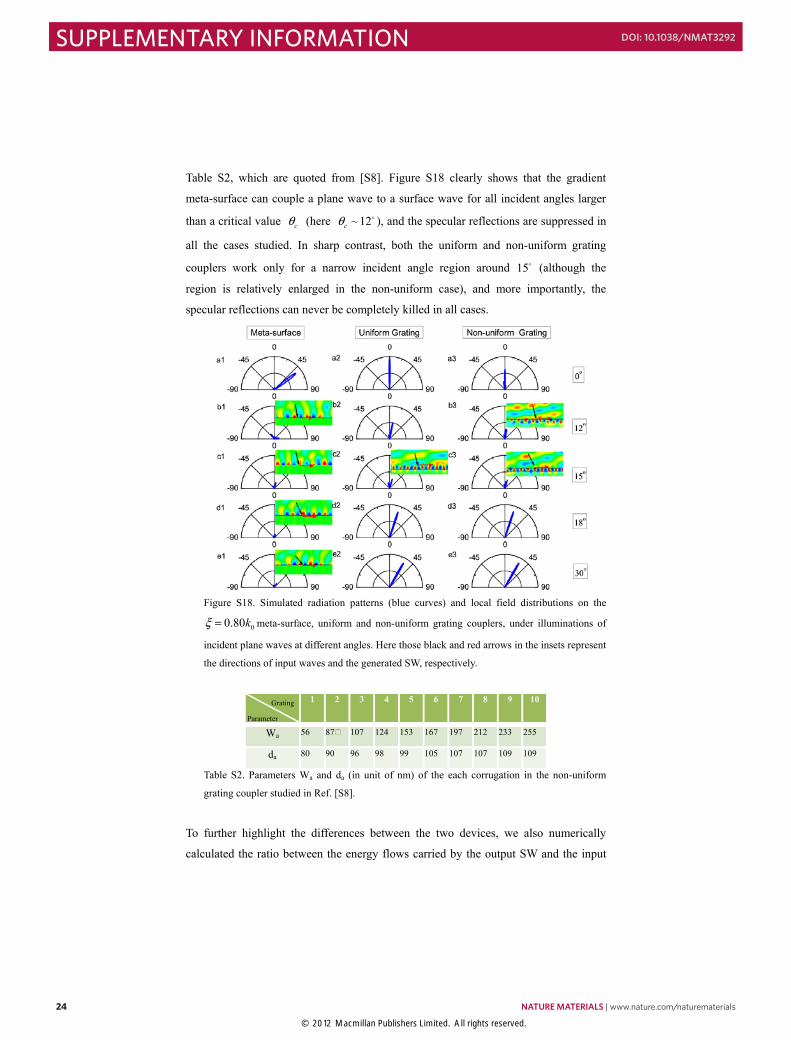
Table S2, which are quoted from [S8]. Figure S18 clearly shows that the gradient
meta-surface can couple a plane wave to a surface wave for all incident angles larger
than a critical value cθ (here ~ 12cθ ), and the specular reflections are suppressed in
all the cases studied. In sharp contrast, both the uniform and non-uniform grating
couplers work only for a narrow incident angle region around 15 (although the
region is relatively enlarged in the non-uniform case), and more importantly, the
specular reflections can never be completely killed in all cases.
Figure S18. Simulated radiation patterns (blue curves) and local field distributions on the
00.80kξ = meta-surface, uniform and non-uniform grating couplers, under illuminations of
incident plane waves at different angles. Here those black and red arrows in the insets represent
the directions of input waves and the generated SW, respectively.
1 2 3 4 5 6 7 8 9 10
Wa 56 87� 107 124 153 167 197 212 233 255
da 80 90 96 98 99 105 107 107 109 109
Table S2. Parameters Wa and da (in unit of nm) of the each corrugation in the non-uniform
grating coupler studied in Ref. [S8].
To further highlight the differences between the two devices, we also numerically
calculated the ratio between the energy flows carried by the output SW and the input
Grating
Parameter
24 NATURE MATERIALS | www.nature.com/naturematerials
SUPPLEMENTARY INFORMATION DOI: 10.1038/NMAT3292
© 2012 Macmillan Publishers Limited. All rights reserved.
- 25 -
PW, /out inP P , for three different systems. To make the calculation tractable and
make the comparison among different systems meaningful, here we studied a
00.8kξ = meta-surface working also at 200 THz (based on the ε μ= model with
thickness 250 nm). The parameters of the two grating systems are just same as those
shown in Table S2 and Figure S18. Here, outP is defined as the total energy flow
leaving the system from the right-hand side on the surface (we integrate the energy
flow in a 2d-wide region near the surface with d being the thickness of the system, see
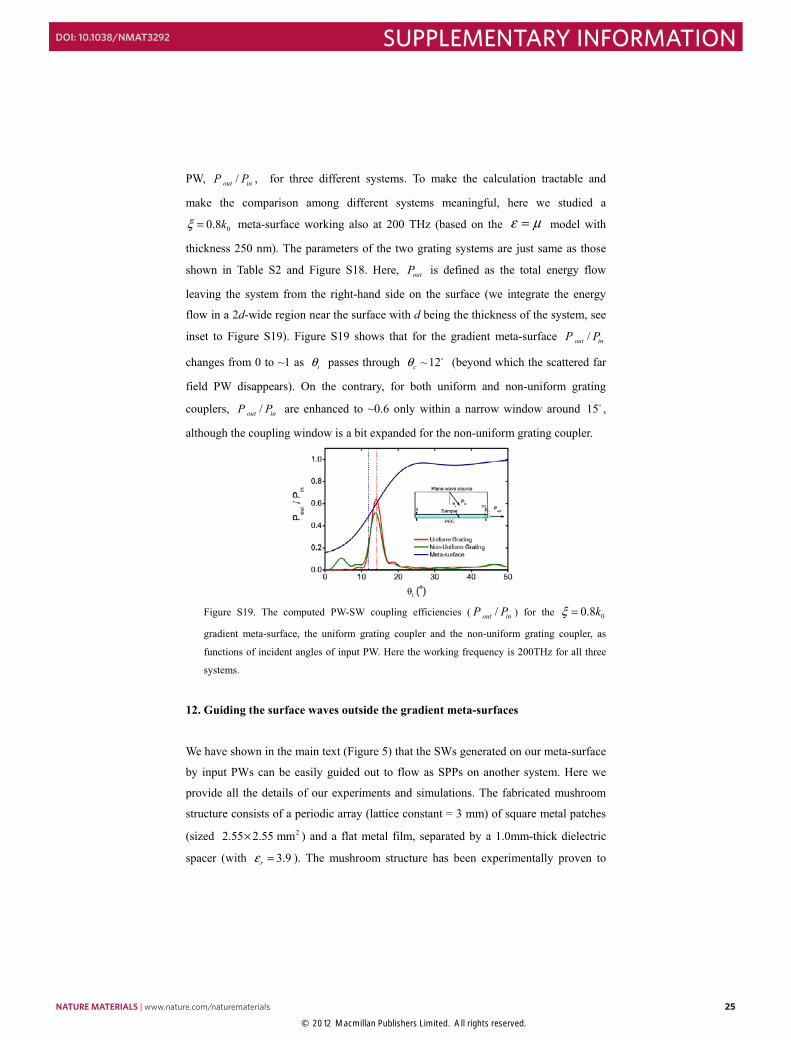
inset to Figure S19). Figure S19 shows that for the gradient meta-surface /out inP P
changes from 0 to ~1 as iθ passes through ~ 12cθ (beyond which the scattered far
field PW disappears). On the contrary, for both uniform and non-uniform grating
couplers, /out inP P are enhanced to ~0.6 only within a narrow window around 15 ,
although the coupling window is a bit expanded for the non-uniform grating coupler.
Figure S19. The computed PW-SW coupling efficiencies ( /out inP P ) for the 00.8kξ =
gradient meta-surface, the uniform grating coupler and the non-uniform grating coupler, as
functions of incident angles of input PW. Here the working frequency is 200THz for all three
systems.
12. Guiding the surface waves outside the gradient meta-surfaces
We have shown in the main text (Figure 5) that the SWs generated on our meta-surface
by input PWs can be easily guided out to flow as SPPs on another system. Here we
provide all the details of our experiments and simulations. The fabricated mushroom
structure consists of a periodic array (lattice constant = 3 mm) of square metal patches
(sized 22.55 2.55 mm× ) and a flat metal film, separated by a 1.0mm-thick dielectric
spacer (with 3.9rε = ). The mushroom structure has been experimentally proven to
NATURE MATERIALS | www.nature.com/naturematerials 25
SUPPLEMENTARY INFORMATIONDOI: 10.1038/NMAT3292
© 2012 Macmillan Publishers Limited. All rights reserved.
- 26 -
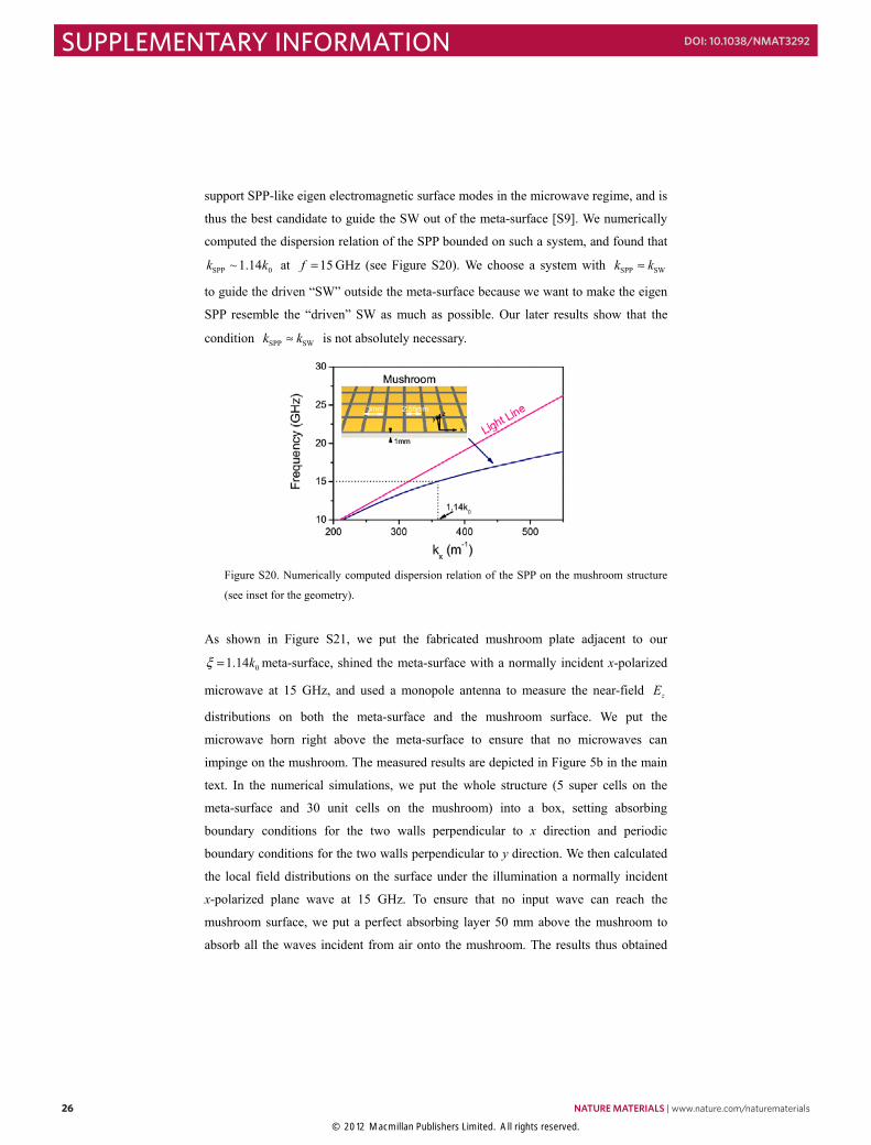
support SPP-like eigen electromagnetic surface modes in the microwave regime, and is
thus the best candidate to guide the SW out of the meta-surface [S9]. We numerically
computed the dispersion relation of the SPP bounded on such a system, and found that
SPP 0~ 1.14k k at 15f = GHz (see Figure S20). We choose a system with SPP SWk k≈
to guide the driven “SW” outside the meta-surface because we want to make the eigen
SPP resemble the “driven” SW as much as possible. Our later results show that the
condition SPP SWk k≈ is not absolutely necessary.
Figure S20. Numerically computed dispersion relation of the SPP on the mushroom structure
(see inset for the geometry).
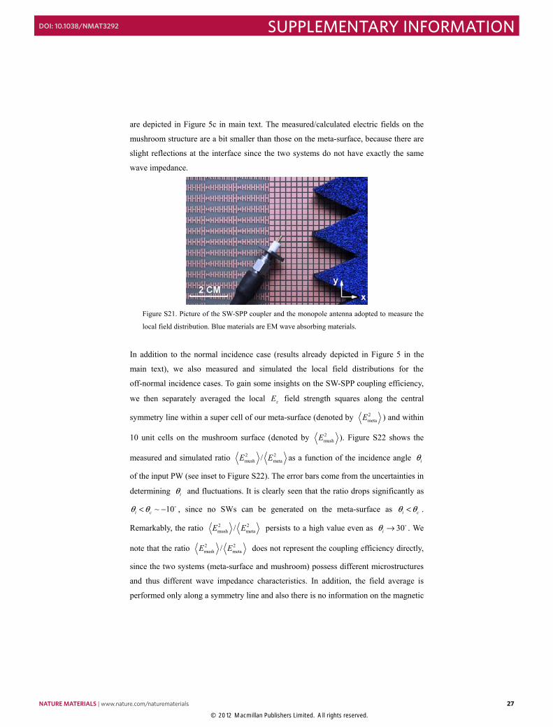
As shown in Figure S21, we put the fabricated mushroom plate adjacent to our
01.14kξ = meta-surface, shined the meta-surface with a normally incident x-polarized
microwave at 15 GHz, and used a monopole antenna to measure the near-field zE
distributions on both the meta-surface and the mushroom surface. We put the
microwave horn right above the meta-surface to ensure that no microwaves can
impinge on the mushroom. The measured results are depicted in Figure 5b in the main
text. In the numerical simulations, we put the whole structure (5 super cells on the
meta-surface and 30 unit cells on the mushroom) into a box, setting absorbing
boundary conditions for the two walls perpendicular to x direction and periodic
boundary conditions for the two walls perpendicular to y direction. We then calculated
the local field distributions on the surface under the illumination a normally incident
x-polarized plane wave at 15 GHz. To ensure that no input wave can reach the
mushroom surface, we put a perfect absorbing layer 50 mm above the mushroom to
absorb all the waves incident from air onto the mushroom. The results thus obtained
26 NATURE MATERIALS | www.nature.com/naturematerials
SUPPLEMENTARY INFORMATION DOI: 10.1038/NMAT3292
© 2012 Macmillan Publishers Limited. All rights reserved.
- 27 -
are depicted in Figure 5c in main text. The measured/calculated electric fields on the
mushroom structure are a bit smaller than those on the meta-surface, because there are
slight reflections at the interface since the two systems do not have exactly the same
wave impedance.
Figure S21. Picture of the SW-SPP coupler and the monopole antenna adopted to measure the
local field distribution. Blue materials are EM wave absorbing materials.
In addition to the normal incidence case (results already depicted in Figure 5 in the
main text), we also measured and simulated the local field distributions for the
off-normal incidence cases. To gain some insights on the SW-SPP coupling efficiency,
we then separately averaged the local zE field strength squares along the central
symmetry line within a super cell of our meta-surface (denoted by 2metaE ) and within
10 unit cells on the mushroom surface (denoted by 2mushE ). Figure S22 shows the
measured and simulated ratio 2 2mush meta/E E as a function of the incidence angle iθ
of the input PW (see inset to Figure S22). The error bars come from the uncertainties in
determining iθ and fluctuations. It is clearly seen that the ratio drops significantly as
~ 10i cθ θ< − , since no SWs can be generated on the meta-surface as i cθ θ< .
Remarkably, the ratio 2 2mush meta/E E persists to a high value even as 30iθ → . We
note that the ratio 2 2mush meta/E E does not represent the coupling efficiency directly,
since the two systems (meta-surface and mushroom) possess different microstructures
and thus different wave impedance characteristics. In addition, the field average is
performed only along a symmetry line and also there is no information on the magnetic
NATURE MATERIALS | www.nature.com/naturematerials 27
SUPPLEMENTARY INFORMATIONDOI: 10.1038/NMAT3292
© 2012 Macmillan Publishers Limited. All rights reserved.
- 28 -
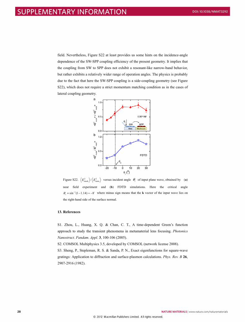
field. Nevertheless, Figure S22 at least provides us some hints on the incidence-angle
dependence of the SW-SPP coupling efficiency of the present geometry. It implies that
the coupling from SW to SPP does not exhibit a resonant-like narrow-band behavior,
but rather exhibits a relatively wider range of operation angles. The physics is probably
due to the fact that here the SW-SPP coupling is a side-coupling geometry (see Figure
S22), which does not require a strict momentum matching condition as in the cases of
lateral coupling geometry.
Figure S22. 2 2
mush meta/E E versus incident angle iθ of input plane wave, obtained by (a)
near field experiment and (b) FDTD simulations. Here the critical angle 1sin (1 1.14) 8cθ −= − ≈ − where minus sign means that the k vector of the input wave lies on
the right-hand side of the surface normal.
13. References
S1. Zhou, L., Huang, X. Q. & Chan, C. T., A time-dependent Green’s function
approach to study the transient phenomena in metamaterial lens focusing. Photonics
Nanostruct. Fundam. Appl. 3, 100-106 (2005). S2. COMSOL Multiphysics 3.5, developed by COMSOL (network license 2008).
S3. Sheng, P., Stepleman, R. S. & Sanda, P. N., Exact eigenfunctions for square-wave
gratings: Application to diffraction and surface-plasmon calculations. Phys. Rev. B 26,
2907-2916 (1982).
28 NATURE MATERIALS | www.nature.com/naturematerials
SUPPLEMENTARY INFORMATION DOI: 10.1038/NMAT3292
© 2012 Macmillan Publishers Limited. All rights reserved.
- 29 -
S4. Garcia-Vidal, F. J., Martin-Moreno, L. & Pendry, J. B., Surfaces with holes in them:
new plasmonic metamaterials. J. Opt. A, Pure Appl. Opt. 7, S97-S101 (2005).
S5. CONCERTO 7.0, Vector Fields Limited, England (2008).
S6. Hao, J. M., Zhou, L. & Chan, C. T. An effective-medium model for
high-impedance surfaces. Appl. Phys. A 87, 281-284 (2007).
S7. Neviere, M., Petit, R., & Cadilhac, M. About the theory of optical grating
coupler-waveguide systems, Opt. Commun. 8, 113-117 (1973).
S8. Tang, Y. B., Wang, Z. C., Wosinski, L., Westergren, U., & He, S. L. Highly
efficient nonuniform grating coupler for silicon-on-insulator nanophotonic circuits.
Opt. Lett. 35, 1290-1292 (2010).
S9. Lockyear, M. J., Hibbins, A. P., & Sambles, J. R. Microwave
Surface-Plasmon-Like Modes on Thin Metamaterials. Phys. Rev. Lett. 102, 073901
(2009).
Supplementary Movie
Movie S1. Time evolution of a continuous x-polarized plane wave (at frequency
15GHz ) striking on the 01.14kξ = meta-surface with top MM layer having
M M 0( ) ( ) 1 / 2x x x k dε μ ξ= = + and 1mmd = .
NATURE MATERIALS | www.nature.com/naturematerials 29
SUPPLEMENTARY INFORMATIONDOI: 10.1038/NMAT3292
© 2012 Macmillan Publishers Limited. All rights reserved.