SUPER MEGOHM METER SM7120
12
SUPER MEGOHM METER SM7110, SM7120, SM7420 Flexible, Multipurpose Design Electrometer Picoammeter IR Meter SM7120 SM7110 SM7420 Max. 1000 V Output 4CH Microcurrent Measurement 300 Times Better Noise Resistance Max. 6.4 ms Measurement Speed Max. 2000 V Output Max. 2×10 19 Ω Display Min. 0.1 fA Resolution SUPER MEGOHM METER
Transcript of SUPER MEGOHM METER SM7120

SUPER MEGOHM METER SM7110, SM7120, SM7420
Flexible, Multipurpose DesignElectrometer Picoammeter
IR Meter
SM7120
SM7110
SM7420
Max. 1000 V Output
4CHMicrocurrent Measurement
300 Times Better Noise Resistance
Max. 6.4 ms Measurement Speed Max. 2000 V Output
Max. 2×10¹⁹ Ω Display Min. 0.1 fA Resolution
SUPER MEGOHM METER
2
Highly stable measurements with strong noise resistance
OUTPUTSM7120: 2000 V OutputSM7110: 1000 V OutputSM7420: INPUT only
High Voltage Output LEDLights When Output is 30 V or Higher(SM7110,SM7120)
INPUTTriaxial BNC
1/60 Variability, 300x Noise ResistanceThe stability you need for high resistance measurements
Advanced 2 kV floating circuitryStability (repeatability) against power supply no ise and ex ternal no ise has improved dramatically due to a combination of new Super Megohm floating circuitry and triaxial connectors.Variability in normal usage environments is reduced to 1/60 compared to previous models, and to 1/300* in conditions where 50 V noise is applied.
* Compared to legacy model, the DSM-8104
Noise 0 VNoise Contamination 50 V
0.42%0.007%
5.26%
0.016%
Repe
atab
ility
for 1
0 pA
Mea
sure
men
t [C
V]
Repeatability by Noise Environment [1 V, SLOW2]
SM0.0%
1.0%
2.0%
3.0%
4.0%
5.0%
6.0%
DSM
Under poor conditionswith noise applied,
reduced to approx. 1/300!Under normal
conditions, variabilityreduced to approx. 1/60!
SMDSM
DSM: DSM-8104, SM: SM7120
Safe Triple Coaxial Structure
GUARD
INPUT
GROUND16 mm large-diameter triaxial connectorThe large-diameter triaxial connector newly adopted for current input terminals has a triple coaxial structure with the internal shield connected to the GUARD (COM) line and the external shield connected to the GROUND.This achieves both stability against noise and safety during high-voltage inspections.
* SM7120
3
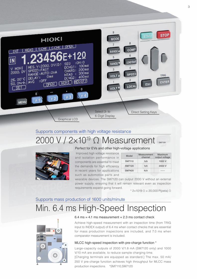
Graphical LCD
Select 3- to 6-Digit Display
Direct Setting Keys
Supports components with high voltage resistance
Supports mass production of 1600 units/minute
2000 V / 2×10¹⁹ Ω Measurement
Min. 6.4 ms High-Speed Inspection6.4 ms = 4.1 ms measurement + 2.3 ms contact checkAchieve high-speed measurement with an inspection time (from TRIG input to INDEX output) of 6.4 ms when contact checks that are essential for mass production inspections are included, and 7.0 ms when comparator measurement is included.
MLCC high-speed inspection with pre-charge function *Large-capacity outputs of 2000 V/1.8 mA (SM7120 only) and 1000 V/10 mA are available, to reduce sample charging time.[Charging terminals are equipped as standard.] The max. 50 mA/ 250 V pre-charge function achieves high throughput for MLCC mass production inspections. *SM7110,SM7120
Perfect for EVs and other high-voltage applications Improved high voltage resistance and isolation performance in components are essential to meet the demands for high efficiency in recent years for applications such as automotive parts and wearable devices. The SM7120 can output 2000 V without an external power supply, ensuring that it will remain relevant even as inspection requirements expand going forward.
* 2×10¹⁹ Ω = 20,000 P(peta) Ω
Model Measurement channel
Maximum output voltage
SM7110 1ch 1000 V
SM7120 1ch 2000 V
SM7420 4ch -----
4
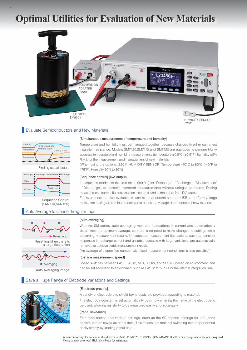
[Simultaneous measurement of temperature and humidity]Temperature and humidity must be managed together, because changes in either can affect insulation resistance. Models SM7120,SM7110 and SM7420 are equipped to perform highly accurate temperature and humidity measurements (temperature ±0.5°C (±0.9°F), humidity ±5% R.H.), for the measurement and management of new materials.(When using the optional Z2011 HUMIDITY SENSOR: Temperature -40°C to 80°C (-40°F to 176°F), Humidity 20% to 80%)
[Sequence control] [D/A output]In sequence mode, set the time (max. 999.9 s) for "Discharge" - "Recharge" - "Measurement" - "Discharge", to perform repeated measurements without using a computer. During measurement, current fluctuations can also be saved to recorders from D/A output.For even more precise evaluations, use external control such as USB to perform voltage resistance testing on semiconductors or to check the voltage dependence of new material.
[Auto averaging]With the SM series, auto averaging monitors fluctuations in current and automatically determines the optimum average, so there is no need to make changes to settings while observing measurement results. Unexpected measurement fluctuations, such as transient responses in recharge current and unstable contacts with large variations, are automatically removed to achieve stable measurement results.(An average of a specified number with fixed measurement conditions is also possible.)
[5-stage measurement speed]Speed switches between FAST, FAST2, MID, SLOW, and SLOW2 based on environment, and can be set according to environment such as FAST2 at ½ PLC for the internal integration time.
Auto Average to Cancel Irregular Input
Evaluate Semiconductors and New Materials
Resetting
Averaging
Discharge
Voltage
Current DA Output
Recharge Measurement Discharge
Sequence Control(SM7110,SM7120)
Auto Averaging Image
Resetting when there is a large fluctuation
Humidity
Temperature
Resistance
Finding actual factors
Temperature and humidity factor
Material factor
[Electrode presets]A variety of electrode and shield box presets are provided according to material.The electrode constant is set automatically by simply entering the name of the electrode to be used, allowing resistivity to be measured easily and accurately.
[Panel save/load]Electrode names and various settings, such as the 60-second settings for sequence control, can be saved as panel data. This means that material switching can be performed easily simply by loading panel data.
Save a Huge Range of Electrode Variations and Settings
Optimal Utilities for Evaluation of New Materials
HUMIDITY SENSOR Z2011
CONVERSION ADAPTERZ5010
ELECTRODESM9001
When connecting electrodes and shield boxes to SM7110/SM7120, CONVERSION ADAPTER Z5010 or a change of connectors is required. Please contact your local Hioki distributor for assistance.
5
Make Mass Production More Practical than Ever
Faster Line Construction
[External interfaces]There are three types of external interface: GP-IB, RS-232C, and USB, as well as the built-in EXT I/O for easy linkage with programmable controllers.
[Communication monitor] [EXT IO test]Because the communication monitor and EXT I/O test function can be used to assess all interfaces, work can be performed while observing operation conditions in real time as necessary during line construction.
EXT I/O Test
Flexible Setup Changes
[Cable length correction]Replace measuring cables without adjustment by simply registering the cable length. (Cable length that can be registered: 0.5 m to 3.0 m (1.64 ft to 9.84 ft))Capacitance contact check functions that are generally included with electrometers and picoammeters will require the impedance matching to be reset whenever the cable length changes. With the SM series, replacement is possible without any adjustments.
[Jig capacity open correction]With the SM series, open correction is provided for jig switching, for a flexible response to changes in line structure without the need for adjustments.
Simple setup
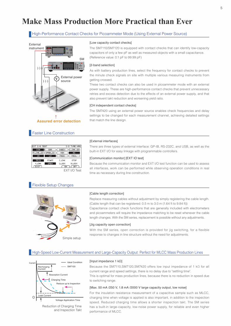
[Input impedance 1 kΩ]Because the SM7110,SM7120,SM7420 offers low input impedance of 1 kΩ for all current range and speed settings, there is no delay due to "settling time".This is optimal for mass production lines, because there is no reduction in speed due to switching range.
[Max. 50 mA /250 V, 1.8 mA /2000 V large capacity output, low noise]For the insulation resistance measurement of a capacitive sample such as MLCC, charging time when voltage is applied is also important, in addition to the inspection speed. Reduced charging time allows a shorter inspection takt. The SM series has a built-in large-capacity, low-noise power supply, for reliable and even higher performance of MLCC.
High-Speed Low-Current Measurement and Large-Capacity Output: Perfect for MLCC Mass Production Lines
Reduction of Charging Time and Inspection Takt
Current
Recharging Current
Absorption Current
Leak Current
Voltage Application Time
Ideal Condition
SM7120
Reduce up to Inspection
Optimal Utilities for Evaluation of New Materials
Charging Time
External power source
SM
External instrument
↑ Assured error detection
High-Performance Contact Checks for Picoammeter Mode (Using External Power Source)
[Low capacity contact checks]The SM7110/SM7120 is equipped with contact checks that can identify low-capacity capacitors of only a few pF as well as measured objects with a small capacitance.(Reference value: 0.1 pF to 99.99 pF)
[2-band selection]As with battery production lines, select the frequency for contact checks to prevent the minute check signals on site with multiple various measuring instruments from getting crossed.These two contact checks can also be used in picoammeter mode with an external power supply. These are high-performance contact checks that prevent unnecessary retries and excess detection due to the effects of an external power supply, and that also prevent takt reduction and worsening yield ratio.
[CH independent contact checks]The SM7420 using an external power source enables check frequencies and delay settings to be changed for each measurement channel, achieving detailed settings that match the line design.
V) ) )
) ) )
6
Roll SampleFlat Material
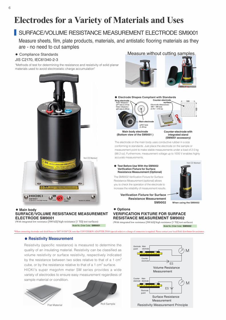
SURFACE/VOLUME RESISTANCE MEASUREMENT ELECTRODE SM9001Measure sheets, film, plate products, materials, and antistatic flooring materials as they are - no need to cut samples
Electrodes for a Variety of Materials and Uses
● Compliance Standards JIS C2170, IEC61340-2-3"Methods of test for determining the resistance and resistivity of solid planar materials used to avoid electrostatic charge accumulation"
Measure without cutting samplesMeasure without cutting samples
The electrode on the main body uses conductive rubber in a size conforming to standards. Just place the electrode on the sample or measurement point to make stable measurements under a load of 2.5 kg (88.2 oz). Furthermore, measurement voltage up to 1000 V enables highly accurate measurements.
Verification Fixture for Surface Resistance Measurement
SM9002 When using the SM9002
The SM9002 Verification Fixture for Surface Resistance Measurement (optional) allows you to check the operation of the electrode to increase the reliability of measurement results.
●● Test Before Use With the Test Before Use With the SM9002 SM9002 Verification Fixture for Surface Verification Fixture for Surface Resistance Measurement (Optional)Resistance Measurement (Optional)
● Electrode Shapes Compliant with Standards
Main body electrode(Bottom view of the SM9001 )
Main electrode
Ring electrode
φ30.5 mm (1.20 in)
Counter-electrode with integrated stand
(SM9001 accessory)
Counter-electrode Counter-electrode surfacesurface
Electrode dimensions:100 × 100 mm (3.94 × 3.94 in)
100
100
●● Main body ●● OptionsSURFACE/VOLUME RESISTANCE MEASUREMENT ELECTRODE SM9001(With integrated low resistance [500 kΩ]/high resistance [1 TΩ] test surfaces)
VERIFICATION FIXTURE FOR SURFACE RESISTANCE MEASUREMENT SM9002(With integrated low resistance [500 kΩ]/high resistance [1 TΩ] test surfaces)
● Resistivity MeasurementResistivity (specific resistance) is measured to determine the quality of an insulating material. Resistivity can be classified as volume resistivity or surface resistivity, respectively indicated by the resistance between two sides relative to that of a 1 cm3 cube, or by the resistance relative to that of a 1 cm2 surface.HIOKI’s super megohm meter SM series provides a wide variety of electrodes to ensure easy measurement regardless of sample material or condition.
Inner diameter: φ57 mm (2.24 in)Outer diameter: φ63 mm (2.48 in)
Resistivity Measurement Principle
Main electrode
Counter-electrode
Electrodeguard
Main electrode
Counter-electrode
Electrodeguard
Volume Resistance Measurement
Surface Resistance Measurement
*When connecting electrodes and shield boxes to SM7110/SM7120, note that CONVERSION ADAPTER Z5010 (special order) or a change of connectors is required. Please contact your local Hioki distributor for assistance.
Not CE Marked
Not CE Marked
Model No. (Order Code) SM9001 Model No. (Order Code) SM9002
7
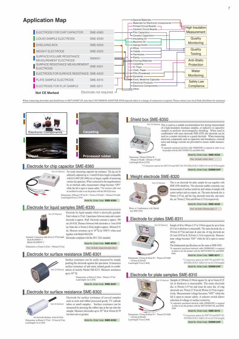
Application MapApplication Map Special MaterialsMaterials for Electronic ComponentsPrinted Circuit BoardsCeramic Circuit BoardsFilm CapacitorsCeramic CapacitorsInsulating OilMachine OilIsopropyl AlcoholWiresCablesHarnessesPaintsFlooring MaterialsCarpetingIC TraysCloth, PaperPills (Powdered)DynamiteFood, Medicine CapsulesElectrical ProductsElectronic ComponentsOther
High Insulation Measurement
Quality Monitoring
Quality Testing
Anti-Static Protection
Water Monitoring
Safety Law Compliance
ELECTRODE FOR CHIP CAPACITOR SME-8360
LIQUID SAMPLE ELECTRODE SME-8330
SHIELDING BOX SME-8350
WEIGHT ELECTRODE SME-8320
SURFACE/VOLUME RESISTANCE MEASUREMENT ELECTRODE SM9001
SURFACE RESISTANCE MEASUREMENT ELECTRODE SME-8301
ELECTRODE FOR SURFACE RESISTANCE SME-8302
PLATE SAMPLE ELECTRODE SME-8310
ELECTRODE FOR FLAT SAMPLE SME-8311
Electrode not requiredNot CE Marked
* Connection option for SM7110 and SM7120: INTERLOCK CABLE (0.1 m (0.33 ft) length)
Electronic Components
Liquid Processed rubber
Carpeting
When connecting electrodes and shield boxes to SM7110/SM7120, note that CONVERSION ADAPTER Z5010 (special order) or a change of connectors is required. Please contact your local Hioki distributor for assistance.
Electrode for liquid samples which is electrically guarded. Total volume is 25 ml. Capacitance between main and counter electrode is approx. 45 pF. Electrode constant is approx. 500 cm (16.41 ft). Distance between both electrodes is 1 mm (0.04 in). Outer dia. is 36 mm (1.42 in), height is approx. 140 mm (5.51 in). Measure resistance up to 1019 Ω (at 1000 V) when used together with Model SM-8220.Electrodes compliant with the JIS C 2101 standard.Included: Connection cable 60 cm (1.97 ft) length
(Red) 0GA00029 ×1 (Black) 0GA00030 ×1
Electrode for liquid samples SME-8330
Dimensions: φ 36 mm (1.42 in) × 140 mm (5.51 in)
Sample of 100 mm (3.94 in) square by up to 8 mm (0.31 in) in thickness is measurable. The main electrode dia. is 50 mm (1.97 in) and inner & outer dia. of ring electrode are 70 mm (2.76 in) & 80 mm (3.15 in) respec-tively. Measurement voltage becomes "OFF" while the lid is open to ensure safety. A selector switch allows selection of voltage or surface resistivity.*A separately purchased interlock cable (DSM8104F) is required
in order to use the product with the SM7110/SM7120, and DSM-8104.
Dimensions: 215 mm (8.46 in) W × 78 mm (3.07 in)H × 165 mm (6.50 in)D
Lead length 75 cm (2.46 ft)
Electrode for plate samples SME-8310
Sample of 40 to 100 mm (1.57 to 3.94 in) square by up to 8 mm (0.31 in) in thickness is measurable. The main electrode dia. is 19.6 mm (0.77 in) and inner & outer dia. of ring electrode are 24.1 mm (0.95 in) & 28.8 mm (1.13 in) respectively. Measure-ment voltage becomes "OFF" while the lid is open to ensure safety.The fundamental specifications are the same as SME-8310.*A separately purchased interlock cable (DSM8104F) is required
in order to use the product with the SM7110/SM7120, and DSM-8104.
Dimensions: 215 mm (8.46 in) W × 78 mm (3.07 in)H × 165 mm (6.50 in)D
Lead length 75 cm (2.46 ft)
Electrode for plates SME-8311
Surface resistance can be easily measured by simply pushing the electrode against the specimen. It measures surface resistance of anti-static related goods in combi-nation of mainly Model SM-8213. Measure resistance up to 1011 Ω.
Dimensions: φ 60 mm (2.36 in) × 50 mm (1.97 in)Lead length 1 m (3.28 ft)
Electrode for surface resistance SME-8301
This is an electrode for plate sample for use together with SME-8350 shield box. This electrode enables extremely easy measurement of surface resistivity and volume of sample with coarse surface such as carpets, etc. The main electrode dia. is 50 mm (1.97 in), and the ring electrode inner-dia. and outer-dia. are 70 mm (2.76 in) and 80 mm (3.15 in) respectively.
Photo is Combination with Shield box SME-8350
Weight electrode SME-8320
Not CE Marked
Not CE Marked
Not CE Marked
Not CE Marked
Not CE Marked
Note: Includes inspection data sheet
Model No. (Order Code) SME-8301
Model No. (Order Code) SME-8311
Model No. (Order Code) SME-8320
Model No. (Order Code) SME-8310
Model No. (Order Code) SME-8330
Note: Included: Banana plug ×2
For easily measuring capacitor tip resistance. The jig can be arbitrarily adjusted up to 11 mm (0.43 in) in length (compatible with EIA 0603 [JIS 1608] size or larger), capable of measuring various tip capacitors. When connected to the megohmmeters by an interlock cable, measurement voltage becomes “OFF” while the lid is open to ensure safety. *The interlock cable must be modified in order to use the product with the SM-8220 series.
Electrode for chip capacitor SME-8360
Dimensions: 200 mm (7.87 in) W × 52 mm (2.05 in)H × 150 mm (5.91 in)DLead length 85 cm (2.79 ft)
Not CE Marked
Model No. (Order Code) SME-8360
Electrode for surface resistance of curved samples such as resin and rubber processed goods, TV cathode tubes or small samples. Surface resistance can be measured by pressing the rubber tips at the tip onto the sample. Measure electrodes up to 1011 Ω at 10 mm (0.39 in) intervals or greater.
Dimensions: φ 40 mm (1.57 in) × 115 mm (4.53 in), Lead length 1 m (3.28 ft)
Electrode for surface resistance SME-8302
An electrode distance: 4 mm (0.16 in)
Not CE Marked
Model No. (Order Code) SME-8302
This is used as a sample accommodation box during measurement of a high-insulation resistance samples, or inductive or capacitive samples to perform electromagnetic shielding. When used in combination with mass electrode SME-8320, the electrode can be used as a counter electrode or a guard electrode. When measuring electronic components such as capacitors and transducers, external noise and leakage currents are prevented to ensure stable measure-ment.*A separately purchased interlock cable (DSM8104F) is required in order to use
the product with the SM7110/SM7120, and DSM-8104.
Shield box SME-8350Not CE Marked
Model No. (Order Code) SME-8350
Note: Includes rubber sheetDimensions: 250 mm (9.84 in) W ×
100 mm (3.94 in)H × 200 mm (7.87 in)DLead length 80 cm (2.62 ft)
Model No. (Order Code) DSM8104F
* Connection option for SM7110 and SM7120: INTERLOCK CABLE (0.1 m (0.33 ft) length)
Model No. (Order Code) DSM8104F
* Connection option for SM7110 and SM7120: INTERLOCK CABLE (0.1 m (0.33 ft) length)
Model No. (Order Code) DSM8104F
8
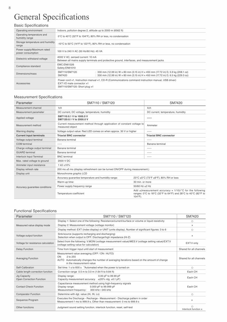
General SpecificationsOperating environment Indoors, pollution degree 2, altitude up to 2000 m (6562 ft)Operating temperature and humidity range 0°C to 40°C (32°F to 104°F), 80% RH or less, no condensation
Storage temperature and humidity range -10°C to 50°C (14°F to 122°F), 80% RH or less, no condensation
Power supply/Maximum rated power consumption 100 V to 240 V AC (50 Hz/60 Hz): 45 VA
Dielectric withstand voltage 4000 V AC, sensed current: 10 mABetween all mains supply terminals and protective ground, interfaces, and measurement jacks
Compliance standard EMC:EN61326Safety:EN61010
Dimensions/mass SM7110/SM7120SM7420
: 330 mm (12.99 in) W × 80 mm (3.15 in) H × 450 mm (17.72 in) D, 5.9 kg (208.1 oz) : 330 mm (12.99 in) W × 80 mm (3.15 in) H × 450 mm (17.72 in) D, 6.5 kg (229.3 oz)
AccessoriesPower cord ×1, Instruction manual ×1, CD-R (Communications command instruction manual, USB driver)EXT I/O male connector ×1SM7110/SM7120: Short plug ×1
Parameter SM7110 / SM7120 SM7420Measurement channel 1ch 4chMeasurement parameter DC current, DC voltage, temperature, humidity DC current, temperature, humidity
Applied voltage SM7110:0.1 V to 1000.0 VSM7120:0.1 V to 2000.0 V -----
Measurement method Current measurement method through application of constant voltage to measured object Ammeter
Warning display Voltage output value: Red LED comes on when approx. 30 V or higher -----Current input terminals Triaxial BNC connector Triaxial BNC connectorVoltage output terminal Banana terminal -----COM terminal ----- Banana terminalCharge voltage output terminal Banana terminal -----GUARD terminal Banana terminal -----Interlock Input Terminal BNC terminal -----Max. rated voltage to ground 2000 V DCAmmeter input resistance 1 kΩ ±10%Display refresh rate 200 ms ±5 ms (display refreshment can be turned ON/OFF during measurement.)Display unit Monochrome graphic LCD
Accuracy guarantee conditions
Accuracy guarantee temperature and humidity range: 23°C ±5°C (73°F ±9°F), 80% RH or lessWarm-up time: 30 min. or morePower supply frequency range 50/60 Hz ±2 Hz
Temperature coefficientAdd ±(measurement accuracy × 1/10)/°C for the following ranges: 0°C to 18°C (32°F to 64°F) and 28°C to 40°C (82°F to 104°F).
Measurement Specifications
Basic Specifications
Functional SpecificationsParameter SM7110 / SM7120 SM7420
Measured value display modeDisplay 1: Select one of the following: Resistance/current/surface or volume or liquid resistivity ○Display 2: Measurement voltage (voltage monitor) ×Display method: EXT (index display) or UNIT (units display), Number of significant figures: 3 to 6 ○
Voltage output function Sink/source (supports recharging and discharging)Selection when output is OFF: Discharge/high impedance (Hi-Z) ×
Voltage for resistance calculation Select from the following: V.MONI (voltage measurement value)/MES.V (voltage setting value)/EXT.V (voltage setting value for calculation) EXT.V only
Delay Function Time from trigger input until start of measurement Shared for all channels
Averaging Function
Measurement value averaging (OFF / ON / AUTO)ON 2 to 255AUTO Automatically changes the number of averaging iterations based on the amount of change
in the measurement value
Shared for all channels
Self-Calibration Set time: 1 s to 600 s *Automated when the power is turned on ○Cable length correction function Correction range 0.5 m to 3.0 m (1.64 ft to 9.84 ft) Each CHJig CapacityOpen Correction Function
Display range: 0.00 pF to 99.99 pFCapacity measurement accuracy ±(20% rdg. ±0.1 pF) Each CH
Contact Check FunctionCapacitance measurement method using high-frequency signalsDisplay range: 0.000 pF to 99.999 pF Measurement frequency: 300 kHz / 245 kHz
Each CH
Comparator Function Determine with dgt. value (Hi, IN, Lo) ○Sequence Program Executes the Discharge - Recharge - Measurement - Discharge pattern in order
Measurement:1 ms to 999.9 s, Other than measurement: 0 ms to 999.9 s ×
Other functions Judgment sound setting function, interlock function, reset, self-test ○Interlock function ×
9
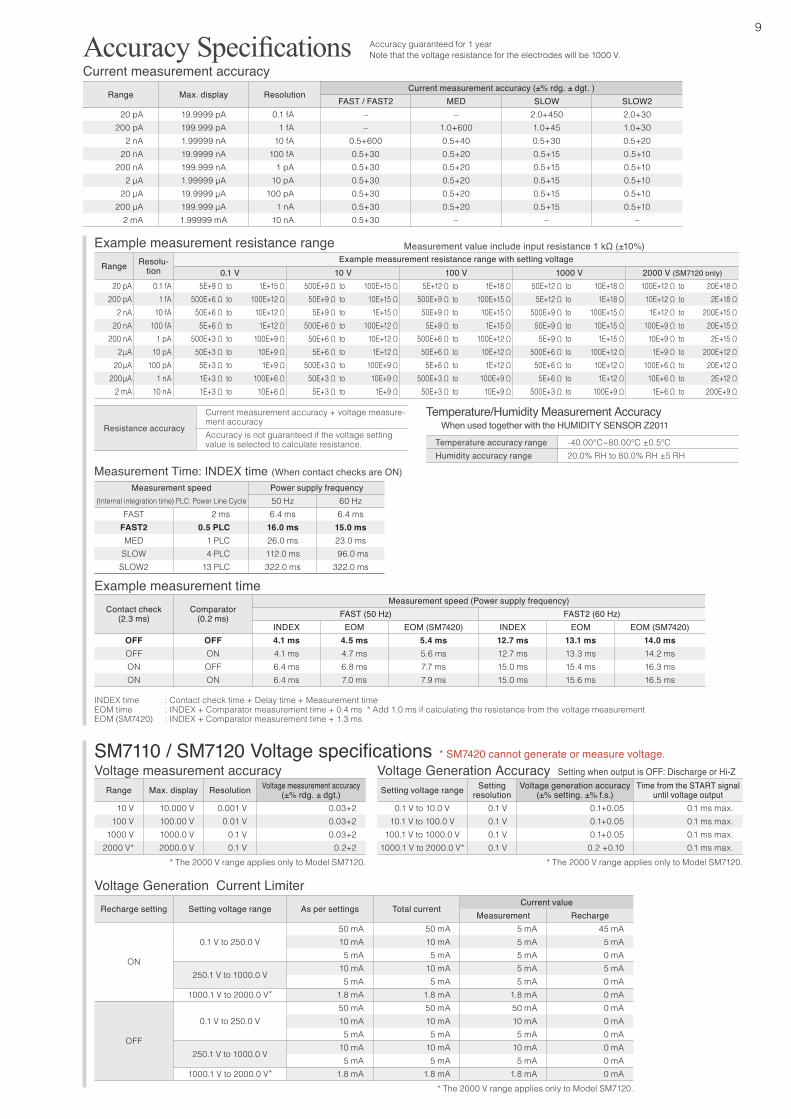
Voltage measurement accuracy Voltage Generation Accuracy Setting when output is OFF: Discharge or Hi-Z
Temperature/Humidity Measurement Accuracy
Current measurement accuracyAccuracy Specifications
SM7110 / SM7120 Voltage specifications
Voltage Generation Current Limiter
Measurement Time: INDEX time (When contact checks are ON)
Example measurement time
Accuracy guaranteed for 1 year
Range Max. display ResolutionCurrent measurement accuracy (±% rdg. ± dgt. )
FAST / FAST2 MED SLOW SLOW220 pA 19.9999 pA 0.1 fA – – 2.0+450 2.0+30
200 pA 199.999 pA 1 fA – 1.0+600 1.0+45 1.0+302 nA 1.99999 nA 10 fA 0.5+600 0.5+40 0.5+30 0.5+20
20 nA 19.9999 nA 100 fA 0.5+30 0.5+20 0.5+15 0.5+10200 nA 199.999 nA 1 pA 0.5+30 0.5+20 0.5+15 0.5+10
2 μA 1.99999 μA 10 pA 0.5+30 0.5+20 0.5+15 0.5+1020 μA 19.9999 μA 100 pA 0.5+30 0.5+20 0.5+15 0.5+10
200 μA 199.999 μA 1 nA 0.5+30 0.5+20 0.5+15 0.5+102 mA 1.99999 mA 10 nA 0.5+30 – – –
Recharge setting Setting voltage range As per settings Total currentCurrent value
Measurement Recharge
ON
0.1 V to 250.0 V50 mA 50 mA 5 mA 45 mA10 mA 10 mA 5 mA 5 mA5 mA 5 mA 5 mA 0 mA
250.1 V to 1000.0 V10 mA 10 mA 5 mA 5 mA5 mA 5 mA 5 mA 0 mA
1000.1 V to 2000.0 V* 1.8 mA 1.8 mA 1.8 mA 0 mA
OFF
0.1 V to 250.0 V50 mA 50 mA 50 mA 0 mA10 mA 10 mA 10 mA 0 mA5 mA 5 mA 5 mA 0 mA
250.1 V to 1000.0 V10 mA 10 mA 10 mA 0 mA5 mA 5 mA 5 mA 0 mA
1000.1 V to 2000.0 V* 1.8 mA 1.8 mA 1.8 mA 0 mA
Range Max. display Resolution Voltage measurement accuracy(±% rdg. ± dgt.)
10 V 10.000 V 0.001 V 0.03+2100 V 100.00 V 0.01 V 0.03+2
1000 V 1000.0 V 0.1 V 0.03+22000 V* 2000.0 V 0.1 V 0.2+2
Setting voltage range Setting resolution
Voltage generation accuracy(±% setting. ±% f.s.)
Time from the START signal until voltage output
0.1 V to 10.0 V 0.1 V 0.1+0.05 0.1 ms max.10.1 V to 100.0 V 0.1 V 0.1+0.05 0.1 ms max.
100.1 V to 1000.0 V 0.1 V 0.1+0.05 0.1 ms max.1000.1 V to 2000.0 V* 0.1 V 0.2 +0.10 0.1 ms max.
Note that the voltage resistance for the electrodes will be 1000 V.
Measurement speed Power supply frequency(Internal integration time) PLC: Power Line Cycle 50 Hz 60 Hz
FAST 2 ms 6.4 ms 6.4 msFAST2 0.5 PLC 16.0 ms 15.0 msMED 1 PLC 26.0 ms 23.0 ms
SLOW 4 PLC 112.0 ms 96.0 msSLOW2 13 PLC 322.0 ms 322.0 ms
Temperature accuracy range -40.00℃~80.00℃ ±0.5℃Humidity accuracy range 20.0% RH to 80.0% RH ±5 RH
Contact check(2.3 ms)
Comparator(0.2 ms)
Measurement speed (Power supply frequency)FAST (50 Hz) FAST2 (60 Hz)
INDEX EOM EOM (SM7420) INDEX EOM EOM (SM7420)OFF OFF 4.1 ms 4.5 ms 5.4 ms 12.7 ms 13.1 ms 14.0 msOFF ON 4.1 ms 4.7 ms 5.6 ms 12.7 ms 13.3 ms 14.2 msON OFF 6.4 ms 6.8 ms 7.7 ms 15.0 ms 15.4 ms 16.3 msON ON 6.4 ms 7.0 ms 7.9 ms 15.0 ms 15.6 ms 16.5 ms
When used together with the HUMIDITY SENSOR Z2011
INDEX time : Contact check time + Delay time + Measurement timeEOM time : INDEX + Comparator measurement time + 0.4 ms * Add 1.0 ms if calculating the resistance from the voltage measurementEOM (SM7420) : INDEX + Comparator measurement time + 1.3 ms
* SM7420 cannot generate or measure voltage.
Example measurement resistance range Measurement value include input resistance 1 kΩ (±10%)
Range Resolu-tion
Example measurement resistance range with setting voltage0.1 V 10 V 100 V 1000 V 2000 V (SM7120 only)
20 pA 0.1 fA 5E+9 Ω to 1E+15 Ω 500E+9 Ω to 100E+15 Ω 5E+12 Ω to 1E+18 Ω 50E+12 Ω to 10E+18 Ω 100E+12 Ω to 20E+18 Ω 200 pA 1 fA 500E+6 Ω to 100E+12 Ω 50E+9 Ω to 10E+15 Ω 500E+9 Ω to 100E+15 Ω 5E+12 Ω to 1E+18 Ω 10E+12 Ω to 2E+18 Ω
2 nA 10 fA 50E+6 Ω to 10E+12 Ω 5E+9 Ω to 1E+15 Ω 50E+9 Ω to 10E+15 Ω 500E+9 Ω to 100E+15 Ω 1E+12 Ω to 200E+15 Ω 20 nA 100 fA 5E+6 Ω to 1E+12 Ω 500E+6 Ω to 100E+12 Ω 5E+9 Ω to 1E+15 Ω 50E+9 Ω to 10E+15 Ω 100E+9 Ω to 20E+15 Ω
200 nA 1 pA 500E+3 Ω to 100E+9 Ω 50E+6 Ω to 10E+12 Ω 500E+6 Ω to 100E+12 Ω 5E+9 Ω to 1E+15 Ω 10E+9 Ω to 2E+15 Ω2 μA 10 pA 50E+3 Ω to 10E+9 Ω 5E+6 Ω to 1E+12 Ω 50E+6 Ω to 10E+12 Ω 500E+6 Ω to 100E+12 Ω 1E+9 Ω to 200E+12 Ω
20 μA 100 pA 5E+3 Ω to 1E+9 Ω 500E+3 Ω to 100E+9 Ω 5E+6 Ω to 1E+12 Ω 50E+6 Ω to 10E+12 Ω 100E+6 Ω to 20E+12 Ω200 μA 1 nA 1E+3 Ω to 100E+6 Ω 50E+3 Ω to 10E+9 Ω 500E+3 Ω to 100E+9 Ω 5E+6 Ω to 1E+12 Ω 10E+6 Ω to 2E+12 Ω
2 mA 10 nA 1E+3 Ω to 10E+6 Ω 5E+3 Ω to 1E+9 Ω 50E+3 Ω to 10E+9 Ω 500E+3 Ω to 100E+9 Ω 1E+6 Ω to 200E+9 Ω
Resistance accuracy
Current measurement accuracy + voltage measure-ment accuracyAccuracy is not guaranteed if the voltage setting value is selected to calculate resistance.
* The 2000 V range applies only to Model SM7120. * The 2000 V range applies only to Model SM7120.
* The 2000 V range applies only to Model SM7120.
10
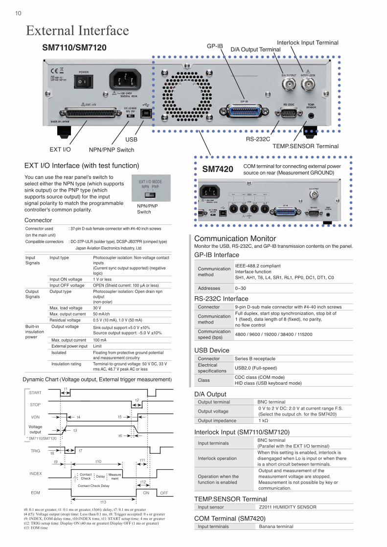
You can use the rear panel's switch to select either the NPN type (which supports sink output) or the PNP type (which supports source output) for the input signal polarity to match the programmable controller's common polarity.
t0: 0.1 ms or greater, t1: 0.1 ms or greater, t3(t6): delay, t7: 0.1 ms or greatert4 (t5): Voltage output (stop) time: Less than 0.1 ms, t8: Trigger accepted: 0 s or greatert9: INDEX, EOM delay time, t10:INDEX time, t11: START setup time: 4 ms or greatert12: TRIG setup time: Display ON (40 ms or greater) Display OFF (1 ms or greater)t13: EOM time
EXT I/O Interface (with test function)
SM7110/SM7120
SM7420
Voltage output
ContactCheck Delay Measure
ment
Dynamic Chart (Voltage output, External trigger measurement)
Input Signals
Input type Photocoupler isolation: Non-voltage contact inputs(Current sync output supported) (negative logic)
Input ON voltage 1 V or lessInput OFF voltage OPEN (Shield current: 100 μA or less)
Output Signals
Output type Photocoupler isolation: Open drain npn output(non-polar)
Max. load voltage 30 VMax. output current 50 mA/chResidual voltage 0.5 V (10 mA), 1.0 V (50 mA)
Built-ininsulation power
Output voltage Sink output support:+5.0 V ±10%Source output support: -5.0 V ±10%
Max. output current 100 mAExternal power input LimitIsolated Floating from protective ground potential
and measurement circuitryInsulation rating Terminal-to-ground voltage: 50 V DC, 33 V
rms AC, 46.7 V peak AC or less
Connector used (on the main unit)Compatible connectors
: 37-pin D-sub female connector with #4-40 inch screws
: DC-37P-ULR (solder type), DCSP-JB37PR (crimped type)Japan Aviation Electronics Industry, Ltd.
Connector
Monitor the USB, RS-232C, and GP-IB transmission contents on the panel.
D/A Output
Interlock Input (SM7110/SM7120)
TEMP.SENSOR Terminal
COM Terminal (SM7420)
Communication Monitor
GP-IB Interface
Communication method
IEEE-488.2 compliantInterface functionSH1, AH1, T6, L4, SR1, RL1, PP0, DC1, DT1, C0
Addresses 0~30
RS-232C InterfaceConnector 9-pin D-sub male connector with #4-40 inch screws
Communication method
Full duplex, start stop synchronization, stop bit of 1 (fixed), data length of 8 (fixed), no parity, no flow control
Communication speed (bps) 4800 / 9600 / 19200 / 38400 / 115200
USB DeviceConnector Series B receptacleElectrical specifications USB2.0 (Full-speed)
Class CDC class (COM mode)HID class (USB keyboard mode)
Output terminal BNC terminal
Output voltage 0 V to 2 V DC: 2.0 V at current range F.S.(Select the output ch. for the SM7420)
Output impedance 1 kΩ
Input terminals BNC terminal(Parallel with the EXT I/O terminal)
Interlock operationWhen this setting is enabled, interlock is disengaged when Lo is input or when there is a short circuit between terminals.
Operation when the function is enabled
Output and measurement of the measurement voltage are stopped.Measurement is not possible by key or communication.
Input sensor Z2011 HUMIDITY SENSOR
Input terminals Banana terminal
D/A Output TerminalInterlock Input Terminal
EXT I/O NPN/PNP SwitchUSB
GP-IB
COM terminal for connecting external power source on rear (Measurement GROUND)
RS-232CTEMP.SENSOR Terminal
External Interface
NPN/PNPSwitch
TRIG
START
STOP
VON
INDEX
EOM
t1
t2
ON OFF
Contact Check Delay
t9
t4
t3
t5
t6
t7t8
t10
t12
t13
t11
* SM7110/SM7120

11
Monitor the USB, RS-232C, and GP-IB transmission contents on the panel.
Model:SUPER MEGOHM METER SM7110SUPER MEGOHM METER SM7120SUPER MEGOHM METER SM7420
Options
Model No. (Order Code) Measurement channel Maximum output voltage RemarksSM7110 1ch 1000 VSM7120 1ch 2000 VSM7420 4ch ----- Dedicated microcurrent measurement
Measurement probe not included with main unit. Please purchase an optional probe that matches your measurement application.
Probes
HUMIDITY SENSOR Z2011HUMIDITY SENSORCord length: 1.5 m (4.92 ft)
Supports 0201 Size Packages* Electrode for SMD Samples SM9060Fine chip electrode with floating structures that can ignore jig surface resistance
Simple chuck for size Simple chuck for size 02010201
OperabilityOperability Measurement PerformanceMeasurement PerformanceAccurate measurement Accurate measurement due to floating structuresdue to floating structures
× ×
When connecting electrodes to a SUPER MEGOHM METER, note a change of connectors is required.
The fine chip is easily secured via the groove, and a dedicated wire probe firmly holds the sample.
During an inspection, the stage lowers so that the surface resistance of the jig can be ignored, allowing the sample to be measured accurately.
* EIA SIZE: 008004
PIN TYPE LEAD (RED) L2230Cable length: 1 m (3.28 ft)
CLIP TYPE LEAD (RED) L2232Cable length: 1 m (3.28 ft)
CLIP TYPE LEAD (BLACK) L2233Cable length: 1 m (3.28 ft)
OPEN LEAD (RED) L2234Cable length: 3 m (9.84 ft)
OPEN LEAD (BLACK) L2235Cable length: 3 m (9.84 ft)
PIN TYPE LEAD (BLACK) L2231Cable length: 1 m (3.28 ft)
This is a resistor box for calibration of the super megohmmeters.Max. voltage is 1000 V DC and resistor value covers from 1 MΩ to 10000 MΩ in 24 points.
Dimensions: 270mm (10.63in) W × 90mm (3.54in)H × 195mm (7.68in)D
Standard resistor box SR-2Not CE Marked
Note: Includes inspection data sheet
Model No. (Order Code) SR-2
Other
Interlock Connection Cable DSM8104F
0.1 m (0.33 ft) lengthNote: Other measurement
electrodes are availableCONVERSION ADAPTER Z5010 Connection between electrode / shielding
box and SM7110, SM7120
For the SM7110, SM7120. Contact your local Hioki distributor for information about the pricing and specifications for the CONVERSION ADAPTER Z5010.
PC comm
unication
RS-232C CABLE 9637 For the PC, 9pin - 9pin,
cross, 1.8m (5.91 ft) length
GP-IB CONNECTOR CABLE 9151-02
2 m (6.56 ft) length
HEADQUARTERS 81 Koizumi, Ueda, Nagano 386-1192 Japan
https://www.hioki.com/
All information correct as of Mar, 22, 2022. All specifications are subject to change without notice. SM7110E10-23E Printed in Japan
DISTRIBUTED BY
Note: Company names and Product names appearing in this catalog are trademarks or registered trademarks of various companies.
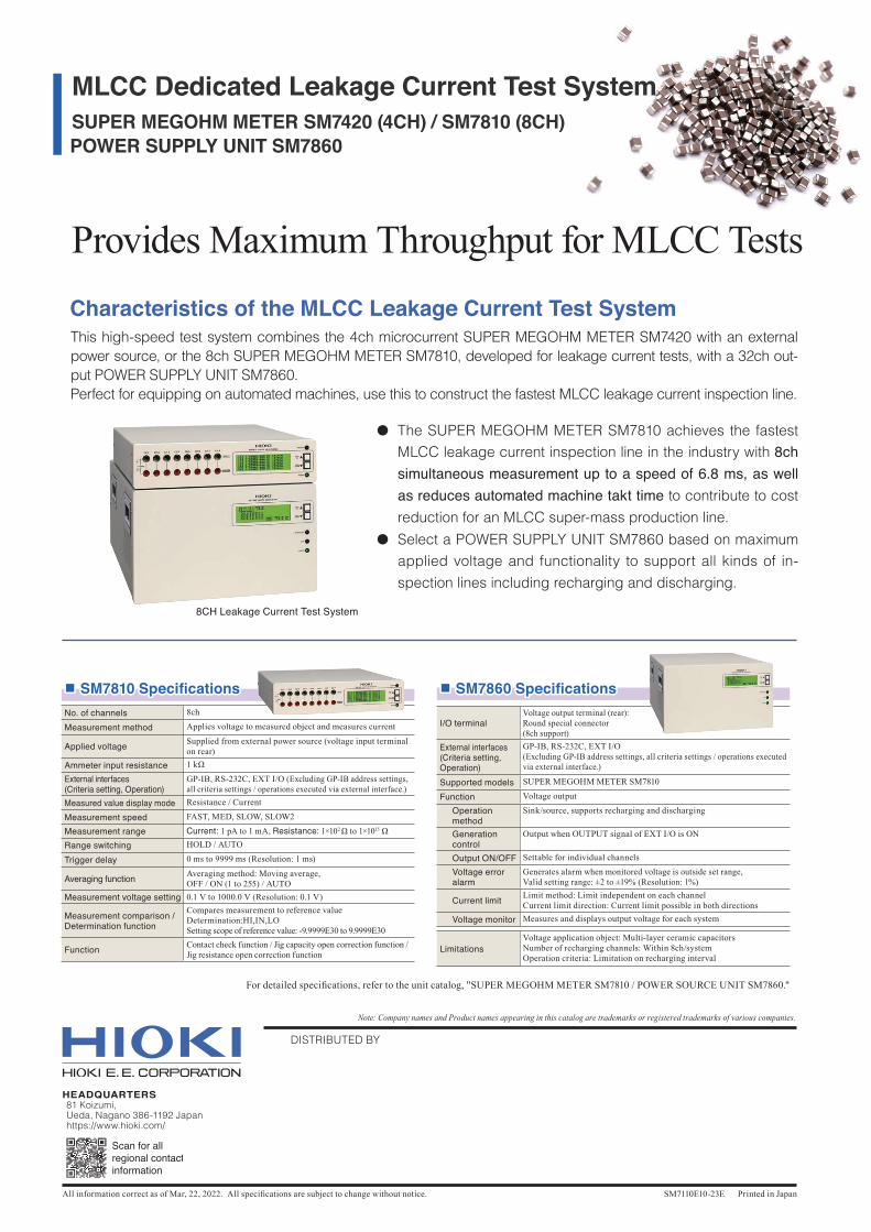
This high-speed test system combines the 4ch microcurrent SUPER MEGOHM METER SM7420 with an external power source, or the 8ch SUPER MEGOHM METER SM7810, developed for leakage current tests, with a 32ch out-put POWER SUPPLY UNIT SM7860.Perfect for equipping on automated machines, use this to construct the fastest MLCC leakage current inspection line.
8CH Leakage Current Test System
Characteristics of the MLCC Leakage Current Test System
Provides Maximum Throughput for MLCC Tests
● The SUPER MEGOHM METER SM7810 achieves the fastest MLCC leakage current inspection line in the industry with 8ch simultaneous measurement up to a speed of 6.8 ms, as well as reduces automated machine takt time to contribute to cost reduction for an MLCC super-mass production line.
● Select a POWER SUPPLY UNIT SM7860 based on maximum applied voltage and functionality to support all kinds of in-spection lines including recharging and discharging.
■■ SM7860 SpecificationsSM7860 Specifications
I/O terminalVoltage output terminal (rear):Round special connector (8ch support)
External interfaces(Criteria setting, Operation)
GP-IB, RS-232C, EXT I/O (Excluding GP-IB address settings, all criteria settings / operations executed via external interface.)
Supported models SUPER MEGOHM METER SM7810
Function Voltage output
Operation method
Sink/source, supports recharging and discharging
Generation control
Output when OUTPUT signal of EXT I/O is ON
Output ON/OFF Settable for individual channels
Voltage error alarm
Generates alarm when monitored voltage is outside set range,Valid setting range: ±2 to ±19% (Resolution: 1%)
Current limit Limit method: Limit independent on each channelCurrent limit direction: Current limit possible in both directions
Voltage monitor Measures and displays output voltage for each system
LimitationsVoltage application object: Multi-layer ceramic capacitorsNumber of recharging channels: Within 8ch/systemOperation criteria: Limitation on recharging interval
■■ SM7810 SpecificationsSM7810 SpecificationsNo. of channels 8ch
Measurement method Applies voltage to measured object and measures current
Applied voltage Supplied from external power source (voltage input terminal on rear)
Ammeter input resistance 1 kΩ
External interfaces(Criteria setting, Operation)
GP-IB, RS-232C, EXT I/O (Excluding GP-IB address settings, all criteria settings / operations executed via external interface.)
Measured value display mode Resistance / Current
Measurement speed FAST, MED, SLOW, SLOW2
Measurement range Current: 1 pA to 1 mA, Resistance: 1×10² Ω to 1×10¹⁵ ΩRange switching HOLD / AUTO
Trigger delay 0 ms to 9999 ms (Resolution: 1 ms)
Averaging function Averaging method: Moving average,OFF / ON (1 to 255) / AUTO
Measurement voltage setting 0.1 V to 1000.0 V (Resolution: 0.1 V)
Measurement comparison / Determination function
Compares measurement to reference valueDetermination:HI,IN,LOSetting scope of reference value: -9.9999E30 to 9.9999E30
Function Contact check function / Jig capacity open correction function /Jig resistance open correction function
For detailed specifications, refer to the unit catalog, "SUPER MEGOHM METER SM7810 / POWER SOURCE UNIT SM7860."
SUPER MEGOHM METER SM7420 (4CH) / SM7810 (8CH) POWER SUPPLY UNIT SM7860
MLCC Dedicated Leakage Current Test System