SUPER 1.24 FF SUPER 2.24 FF SUPER 2.24 CF SUPER 2.28 CF ... · The control panel on INITIA SUPER...
50
SUPER 1.24 FF SUPER 2.24 FF SUPER 2.24 CF SUPER 2.28 CF SUPER 2.31 FF Επιτίιι λέητες αερίυ υψηλής απδσης High efficiency wall-mounted gas-fired boilers Caldera mural de gas de alto rendimento Caldeira de parede a gás de elevado rendimento δηγίες ρήσης εγκαταστάτη και ρήστη Installer’s and User’s Instructions Manual de uso destinado al usuario y al instalador Manual para o uso destinado ao utente e ao instalador
Transcript of SUPER 1.24 FF SUPER 2.24 FF SUPER 2.24 CF SUPER 2.28 CF ... · The control panel on INITIA SUPER...
SUPER 1.24 FFSUPER 2.24 FFSUPER 2.24 CFSUPER 2.28 CFSUPER 2.31 FF
Επιτίιι λέητες αερίυ υψηλής απδσηςHigh efficiency wall-mounted gas-fired boilersCaldera mural de gas de alto rendimentoCaldeira de parede a gás de elevado rendimento
δηγίες ρήσης εγκαταστάτη και ρήστηInstaller’s and User’s Instructions
Manual de uso destinado al usuario y al instaladorManual para o uso destinado ao utente e ao instalador
Dear Customer,Thank you for your purchase of one of our products.Our boilers are made to give you complete satisfaction andare manufactured in compliance with the strictest safetyand quality standards. Our company is ISO 9001 certifiedto ensure that our products and services are of the bestpossible quality.To ensure that your new boiler gives you lasting and efficientservice, please read these instructions before starting touse it. The information given here is designed to help youget the best from your new boiler.
Warning:Keep the items of packaging out of the reach of children.
Make sure that your boiler is regularly serviced.
Current legislation requires your boiler to be servicedonce every year by a qualified service engineer whomust:• service the boiler (check, adjust and clean it, replace
any worn parts and decoke it if necessary);• check the fume venting and burner conduits for
leaks.Boiler service companies will be happy to advise youregarding the most suitable form of annual servicecontract for your boiler. Consult your installer or ourafter sales service for further details.
The product warranty covers manufacturing faults but doesnot extend to the annual service operations describedabove.
Warranty
To ensure the validity of your warranty, your boiler must beinstalled and started up by a qualified service engineer incompliance with applicable legislation, according to strictprofessional and trade standards, and following theinstallation and start-up instructions in the manual.
Αγαπητέ Πελάτη,Είµαστε ευτυείς πυ επιλέατε τ πρϊν µας.Τα boiler κατασκευάνται µε σκπ να παρέυν πλήρη ικανπίηση,τηρώντας τις πι αυστηρές απαιτήσεις ασαλείας καθώς και τα πισ!αρά πρτυπα πιτητς. Πράγµατι, η εταιρία είναι πιστπιηµένηκατά ISO 9001 πρκειµένυ να εασαλίσει ένα απ τα καλύτεραεπίπεδα πιτητς.Πρκειµένυ τ πρϊν να παρέει την καλύτερη εικτήευπηρέτηση, σας συµ!υλεύυµε να δια!άσετε τ παρνενηµερωτικ έντυπ πριν πιαδήπτε ρήση. %ι πληρρίες πυπεριέει θα σας δώσυν την ευκαιρία να εκµεταλλευτείτε στ µέγιστ!αθµ τ boiler σας.
Πρσή:Τα διάρα τµήµατα της συσκευασίας πρέπει να διατηρύνται µακριάαπ τα παιδιά.
Συντηρείτε τακτικά την εγκατάστασή σας
Η ετήσια συντήρηση τυ boiler σας είναι υπρεωτική υπ τυς ρυςτης ισύυσας νµθεσίας. Πρέπει να διεάγεται µια ρά τ ρναπ ειδικ µε τα απαραίτητα πρσντα.- συντήρηση τυ boiler (έλεγς, ρύθµιση, καθαρισµς,
αντικατάσταση των εαρτηµάτων µετά απ υσιλγική θράκαι πιθανή απµάκρυνση των καθαλατώσεων)
- έλεγς για συνέεια τυ αγωγύ απαγωγής και τυ τερµατικύ.Για λες τις λειτυργίες συντήρησης τυ boiler σας, η εταιρίαπαρής υπηρεσιών σας µπρεί να σας πρτείνει εναλλακτικέςσυµ!άσεις ετήσιας συντήρησης. Συµ!υλευθείτε τ πρσωπ πυπραγµατπίησε την εγκατάστασή σας ή τ τµήµα πωλήσεών µας.Η εγγύηση τυ κατασκευαστή, η πία καλύπτει κατασκευαστικάελαττώµατα, δεν πρέπει να συγέεται µε τις λειτυργίες πυπεριγράηκαν παραπάνω.
Εγγύηση
Για να επωεληθείτε απ την εγγύηση, η συσκευή πρέπει ναεγκατασταθεί και να τεθεί σε λειτυργία απ έναν ειδικ σύµωναµε την ισύυσα νµθεσία, µε τν κωδικ της αδείας και τ ΑΦΜτυ, σύµωνα µε τις δηγίες συναρµλγησης και εκκίνησης πυεµανίνται στ έντυπ αυτ.
3
Contents
Instructions pertainingto the userInstructions prior to installation 4Instructions prior to commissioning 4Commissioning of the boiler 4Room temperature adjustment 5DHW temperature adjustment 5Filling the boiler 6Turning off the boiler 6Prolonged standstill of the system. Frost protection(central heating system) 6Gas change 6Safety Device Indicators-Activation 7Servicing instructions 7
Instructions pertainingto the installer
General information 8Instructions prior to installation 8The template to fix the boiler on the wall 10Boiler size 10Installation of flue and air ducts (forced draft models ) 11Connecting the mains supply 16Fitting a room thermostat 16Connecting a programming clock 16Gas change modalities 17Control and operation devices 20Electronic board calibration 21Positioning of the ignition and flame sensing electrode 22Check of combustion parameters 22Output / pump head performances 23How to purge the DHW system from limestone deposits 23How to disassemble the DHW heat exchanger 24Cleaning the cold water filter 24Boiler schematic 25-26Illustrated wiring diagram 27-28-29Connection diagram of gas valve and electric igniter 30Connection of the external probe 31Technical data 32
ΠΕΡΙΕ!ΜΕΝΑ
δηγίες πυ α%ρύν τρήστη
%δηγίες πριν την εκκίνηση 4
Εκκίνηση λέ!ητα 4
Ρύθµιση θερµκρασίας δωµατίυ 5
Ρύθµιση θερµκρασίας εστύ νερύ ρήσης 5
Πλήρωση τυ λέ!ητα 6
Τερµατισµς λειτυργίας τυ λέ!ητα 6
Παύση λειτυργίας για µεγάλ ρνικ διάστηµα.
Αντιπαγετική πρστασία 6
Αλλαγή αερίυ 6
Λυνίες µηανισµών ασαλείας-Ενεργπίηση 7
%δηγίες συντήρησης 7
δηγίες πυ α%ρύν τνεγκαταστάτη
Γενικές πληρρίες 8
%δηγίες πριν την εγκατάσταση 8
Η !άση για τη στήριη τυ λέ!ητα στν τί 10
∆ιαστάσεις λέ!ητα 10
Σύνδεση παρής ρεύµατς 16
Σύνδεση θερµστάτη ώρυ 16
Σύνδεση ρνδιακπτη (Κεντρική Θέρµανση) 16
Φρµες για την αλλαγή αερίυ 17
Συσκευές ελέγυ και λειτυργίας 20
Βαθµνµηση ηλεκτρνικύ πίνακα 21
Τπθέτηση τυ αισθητήρα ανάλεης και λγας 22
Έλεγς των παραµέτρων καύσης 22
Απδση µανµετρικύ ύψυς αντλίας 23
Πώς να καθαρίσετε τ σύστηµα παραγωγής εστύ
νερύ ρήσης απ ασ!εστλιθικά κατακάθια 23
Πώς να απσυνδέσετε τν εναλλάκτη τυ boiler 24
Καθαρισµς τυ ίλτρυ νερύ 24
∆ιαγράµµατα λέ!ητα 25-26
Απεικνιση ∆ιαγράµµατς Καλωδιώσεων 27-28-29
∆ιαγράµµα σύνδεσης !αλ!ίδας αερίυ και
ηλεκτρικύ αναλεκτήρα 30
Σύνδεση εωτερικύ αισθητηρίυ 31
Τενικά αρακτηριστικά 32
4
Instructions prior toinstallationThis boiler is designed to heat water at a lower than boiling temperatureat atmospheric pressure. The boiler must be connected to a central heatingsystem and to a domestic hot water supply system in compliance with itsperformances and output power.Have the boiler installed by a Qualified Service Engineer and ensure thefollowing operations are accomplished:
a) accurate purging of the whole pipework in order to remove anydeposits.
b) careful checking that the boiler is fit for operation with the type of gasavailable. For more details see the notice on the packaging and thelabel on the appliance itself.
c) careful checking that the flue terminal draft is appropriate; that theterminal is not obstructed and that no other appliance exhaust gasesare expelled through the same flue duct, unless the flue is especiallydesigned to collect the exhaust gas coming from more than oneappliance, in conformity with the laws and regulations in force.
d) careful checking that, in case the flue has been connected to pre-existing flue ducts, thorough cleaning has been carried out in thatresidual combustion products may come off during operation of theboiler and obstruct the flue duct.
Instructions prior tocommissioningInitial lighting of the boiler must be carried out by a licensed technician.Ensure the following operations are carried out:a) compliance of boiler parameters with (electricity, water, gas) supply
systems settings.b) compliance of installation with the laws and regulations in force.c) appropriate connection to the power supply and grounding of the
appliance.
Failure to observe the above will render the guarantee null and void.Prior to commissioning remove the protective plastic coating from theunit. Do not use any tools or abrasive detergents as you may spoil thepainted surfaces.
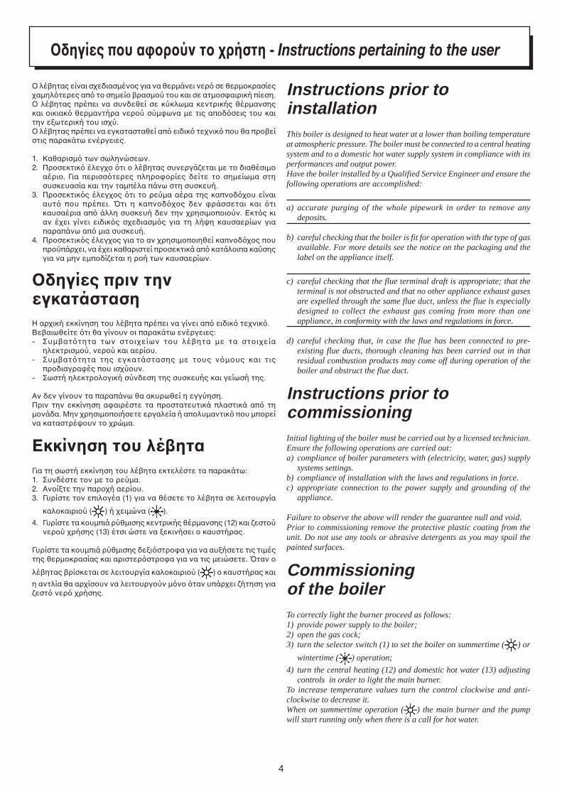
Commissioningof the boilerTo correctly light the burner proceed as follows:1) provide power supply to the boiler;2) open the gas cock;3) turn the selector switch (1) to set the boiler on summertime ( ) or
wintertime ( ) operation;
4) turn the central heating (12) and domestic hot water (13) adjustingcontrols in order to light the main burner.
To increase temperature values turn the control clockwise and anti-clockwise to decrease it.When on summertime operation ( ) the main burner and the pumpwill start running only when there is a call for hot water.
δηγίες πυ α%ρύν τ ρήστη - Instructions pertaining to the user
% λέ!ητας είναι σεδιασµένς για να θερµάνει νερ σε θερµκρασίεςαµηλτερες απ τ σηµεί !ρασµύ τυ και σε ατµσαιρική πίεση.% λέ!ητας πρέπει να συνδεθεί σε κύκλωµα κεντρικής θέρµανσηςκαι ικιακ θερµαντήρα νερύ σύµωνα µε τις απδσεις τυ καιτην εωτερική τυ ισύ.% λέ!ητας πρέπει να εγκατασταθεί απ ειδικ τενικ πυ θα πρ!είστις παρακάτω ενέργειες.
1. Καθαρισµ των σωληνώσεων.2. Πρσεκτικ έλεγ τι λέ!ητας συνεργάεται µε τ διαθέσιµ
αέρι. Για περισστερες πληρρίες δείτε τ σηµείωµα στησυσκευασία και την ταµπέλα πάνω στη συσκευή.
3. Πρσεκτικς έλεγς τι τ ρεύµα αέρα της καπνδυ είναιαυτ πυ πρέπει. Bτι η καπνδς δεν ράσσεται και τικαυσαέρια απ άλλη συσκευή δεν την ρησιµπιύν. Εκτς κιαν έει γίνει ειδικς σεδιασµς για τη λήψη καυσαερίων γιαπαραπάνω απ µια συσκευή.
4. Πρσεκτικς έλεγς για τ αν ρησιµπιηθεί καπνδς πυπρϋπάρει, να έει καθαριστεί πρσεκτικά απ κατάλιπα καύσηςγια να µην εµπδίεται η ρή των καυσαερίων.
δηγίες πριν τηνεγκατάστασηΗ αρική εκκίνηση τυ λέ!ητα πρέπει να γίνει απ ειδικ τενικ.Βε!αιωθείτε τι θα γίνυν ι παρακάτω ενέργειες:- Συµ!αττητα των στιείων τυ λέ!ητα µε τα στιεία
ηλεκτρισµύ, νερύ και αερίυ.- Συµ!αττητα της εγκατάστασης µε τυς νµυς και τις
πρδιαγραές πυ ισύυν.- Σωστή ηλεκτρλγική σύνδεση της συσκευής και γείωσή της.
Αν δεν γίνυν τα παραπάνω θα ακυρωθεί η εγγύηση.Πριν την εκκίνηση ααιρέστε τα πρστατευτικά πλαστικά απ τηµνάδα. Μην ρησιµπιήσετε εργαλεία ή απλυµαντικ πυ µπρείνα καταστρέψυν τ ρώµα.
Εκκίνηση τυ λέηταΓια τη σωστή εκκίνηση τυ λέ!ητα εκτελέστε τα παρακάτω:1. Συνδέστε τν µε τ ρεύµα.2. Ανίτε την παρή αερίυ.3. Γυρίστε τν επιλγέα (1) για να θέσετε τ λέ!ητα σε λειτυργία
καλκαιριύ ( ) ή ειµώνα ( ).
4. Γυρίστε τα κυµπιά ρύθµισης κεντρικής θέρµανσης (12) και εστύνερύ ρήσης (13) έτσι ώστε να εκινήσει καυστήρας.
Γυρίστε τα κυµπιά ρύθµισης δειστρα για να αυήσετε τις τιµέςτης θερµκρασίας και αριστερστρα για να τις µειώσετε. Bταν
λέ!ητας !ρίσκεται σε λειτυργία καλκαιριύ ( ) καυστήρας και
η αντλία θα αρίσυν να λειτυργύν µν ταν υπάρει ήτηση γιαεστ νερ ρήσης.
5
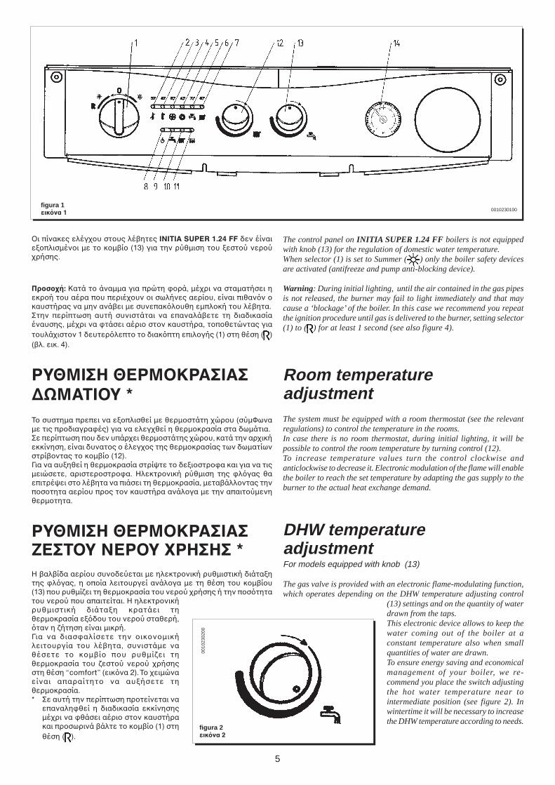
figura 1εικνα 1
The control panel on INITIA SUPER 1.24 FF boilers is not equippedwith knob (13) for the regulation of domestic water temperature.When selector (1) is set to Summer ( ) only the boiler safety devicesare activated (antifreeze and pump anti-blocking device).
Warning: During initial lighting, until the air contained in the gas pipesis not released, the burner may fail to light immediately and that maycause a ‘blockage’ of the boiler. In this case we recommend you repeatthe ignition procedure until gas is delivered to the burner, setting selector(1) to ( ) for at least 1 second (see also figure 4).
Room temperatureadjustmentThe system must be equipped with a room thermostat (see the relevantregulations) to control the temperature in the rooms.In case there is no room thermostat, during initial lighting, it will bepossible to control the room temperature by turning control (12).To increase temperature values turn the control clockwise andanticlockwise to decrease it. Electronic modulation of the flame will enablethe boiler to reach the set temperature by adapting the gas supply to theburner to the actual heat exchange demand.
DHW temperatureadjustmentFor models equipped with knob (13)
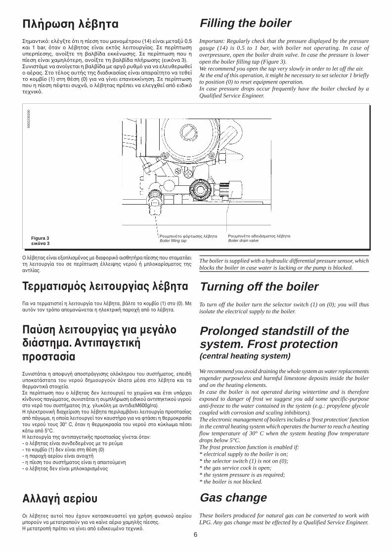
The gas valve is provided with an electronic flame-modulating function,which operates depending on the DHW temperature adjusting control
(13) settings and on the quantity of waterdrawn from the taps.This electronic device allows to keep thewater coming out of the boiler at aconstant temperature also when smallquantities of water are drawn.To ensure energy saving and economicalmanagement of your boiler, we re-commend you place the switch adjustingthe hot water temperature near tointermediate position (see figure 2). Inwintertime it will be necessary to increasethe DHW temperature according to needs.
figura 2εικνα 2
0010230100
%ι πίνακες ελέγυ στυς λέ!ητες INITIA SUPER 1.24 FF δεν έίναιεπλισµένι µε τ κµ!ί (13) για την ρύθµιση τυ εστύ νερύρήσης.
Πρσή: Κατά τ άναµµα για πρώτη ρά, µέρι να σταµατήσει ηεκρή τυ αέρα πυ περιέυν ι σωλήνες αερίυ, είναι πιθανν καυστήρας να µην ανά!ει µε συνεπακλυθη εµπλκή τυ λέ!ητα.Στην περίπτωση αυτή συνιστάται να επαναλά!ετε τη διαδικασίαέναυσης, µέρι να τάσει αέρι στν καυστήρα, τπθετώντας γιατυλάιστν 1 δευτερλεπτ τ διακπτη επιλγής (1) στη θέση ( )(!λ. εικ. 4).
ΡΥΘΜΙΣΗ ΘΕΡΜΚΡΑΣΙΑΣ∆ΩΜΑΤΙΥ *Τ συστηµα πρεπει να επλισθεί µε θερµστάτη ώρυ (σύµΦωναµε τις πρδιαγραές) για να ελεγθεί η θερµκρασία στα δωµάτια.Σε περίπτωση πυ δεν υπάρει θερµστάτης ώρυ, κατά την αρικήεκκίνηση, είναι δυνατς έλεγς της θερµκρασίας των δωµατίωνστρί!ντας τ κµ!ί (12).Για να αυηθεί η θερµκρασία στρίψτε τ δειστρα και για να τιςµειώσετε, αριστερστρα. Ηλεκτρνική ρύθµιση της λγας θαεπιτρέψει στ λέ!ητα να πιάσει τη θερµκρασία, µετα!άλλντας τηνπστητα αερίυ πρς τν καυστήρα ανάλγα µε την απαιτύµενηθερµτητα.
ΡΥΘΜΙΣΗ ΘΕΡΜΚΡΑΣΙΑΣ0ΕΣΤΥ ΝΕΡΥ !ΡΗΣΗΣ *Η !αλ!ίδα αερίυ συνδεύεται µε ηλεκτρνική ρυθµιστική διάταητης λγας, η πία λειτυργεί ανάλγα µε τη θέση τυ κµ!ίυ(13) πυ ρυθµίει τη θερµκρασία τυ νερύ ρήσης ή την πστητατυ νερύ πυ απαιτείται. Η ηλεκτρνικήρυθµιστική διάταη κρατάει τηθερµκρασία εδυ τυ νερύ σταθερή,ταν η ήτηση είναι µικρή.Για να διασαλίσετε την ικνµικήλειτυργία τυ λέ!ητα, συνιστάµε ναθέσετε τ κµ!ί πυ ρυθµίει τηθερµκρασία τυ εστύ νερύ ρήσηςστη θέση “comfort” (εικνα 2). Τ ειµώναείναι απαραίτητ να αυήσετε τηθερµκρασία.* Σε αυτή την περίπτωση πρτείνεται να
επαναληθεί η διαδικασία εκκίνησηςµέρι να θάσει αέρι στν καυστήρακαι πρσωρινά !άλτε τ κµ!ί (1) στηθέση ( ).
0010
2302
00
6
0002
2302
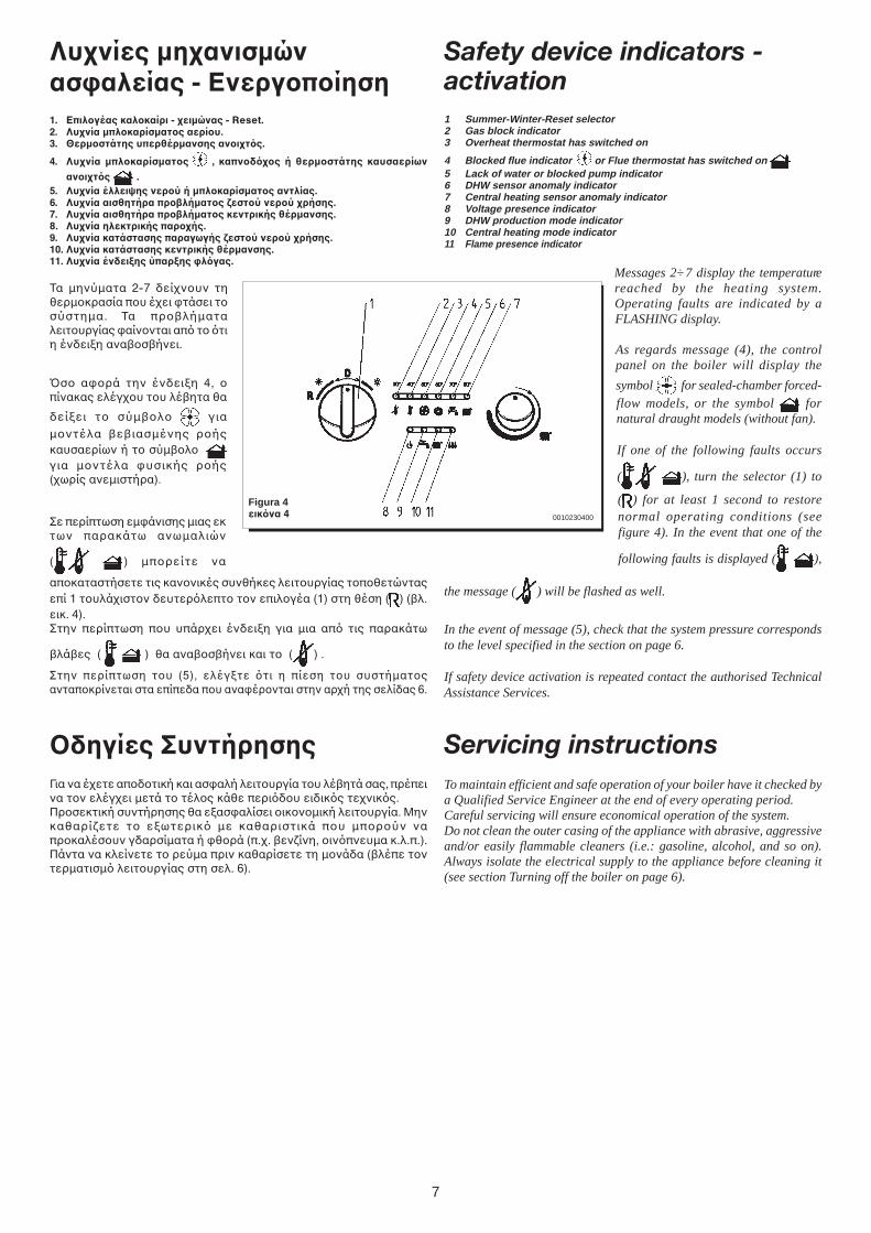
00Filling the boilerImportant: Regularly check that the pressure displayed by the pressuregauge (14) is 0.5 to 1 bar, with boiler not operating. In case ofoverpressure, open the boiler drain valve. In case the pressure is loweropen the boiler filling tap (Figure 3).We recommend you open the tap very slowly in order to let off the air.At the end of this operation, it might be necessary to set selector 1 brieflyto position (0) to reset equipment operation.In case pressure drops occur frequently have the boiler checked by aQualified Service Engineer.
Ρυµπινέτ ρτωσης λέ!ηταBoiler filling tap
Ρυµπινέτ αδειάσµατς λέ!ηταBoiler drain valveFigura 3
εικνα 3
The boiler is supplied with a hydraulic differential pressure sensor, whichblocks the boiler in case water is lacking or the pump is blocked.
Turning off the boilerTo turn off the boiler turn the selector switch (1) on (0); you will thusisolate the electrical supply to the boiler.
Prolonged standstill of thesystem. Frost protection(central heating system)
We recommend you avoid draining the whole system as water replacementsengender purposeless and harmful limestone deposits inside the boilerand on the heating elements.In case the boiler is not operated during wintertime and is thereforeexposed to danger of frost we suggest you add some specific-purposeanti-freeze to the water contained in the system (e.g.: propylene glycolecoupled with corrosion and scaling inhibitors).The electronic management of boilers includes a 'frost protection' functionin the central heating system which operates the burner to reach a heatingflow temperature of 30° C when the system heating flow temperaturedrops below 5°C.The frost protection function is enabled if:* electrical supply to the boiler is on;* the selector switch (1) is not on (0);* the gas service cock is open;* the system pressure is as required;* the boiler is not blocked.
Gas changeThese boilers produced for natural gas can be converted to work withLPG. Any gas change must be effected by a Qualified Service Engineer.
% λέ!ητας είναι επλισµένς µε διαρικ αισθητήρα πίεσης πυ σταµατάειτη λειτυργία τυ σε περίπτωση έλλειψης νερύ ή µπλκαρίσµατς τηςαντλίας.
Τερµατισµς λειτυργίας λέηταΓια να τερµατιστεί η λειτυργία τυ λέ!ητα, !άλτε τ κµ!ί (1) στ (0). Μεαυτν τν τρπ απµνώνεται η ηλεκτρική παρή απ τ λέ!ητα.
Παύση λειτυργίας για µεγάλδιάστηµα. ΑντιπαγετικήπρστασίαΣυνιστάται η απυγή απστράγγισης λκληρυ τυ συστήµατς, επειδήυπκατάστατα τυ νερύ δηµιυργύν άλατα µέσα στ λέ!ητα και ταθερµαντικά στιεία.Σε περίπτωση πυ λέ!ητας δεν λειτυργεί τ ειµώνα και έτσι υπάρεικίνδυνς παγώµατς, συνιστάται η συµπλήρωση ειδικύ αντιπηκτικύ υγρύστ νερ τυ συστήµατς (π.. γλυκλη µε αντιδιεM600glrα).Η ηλεκτρνική διαείριση τυ λέ!ητα περιλαµ!άνει λειτυργία πρστασίαςαπ πάγωµα, η πία λειτυργεί τν καυστήρα για να τάσει η θερµκρασίατυ νερύ τυς 30° C, ταν η θερµκρασία τυ νερύ στ κύκλωµα πέσεικάτω απ 5°C.Η λειτυργία της αντιπαγετικής πρστασίας γίνεται ταν:- λέ!ητας είναι συνδεδεµένς µε τ ρεύµα- τ κµ!ί (1) δεν είναι στη θέση (0)- η παρή αερίυ είναι ανιτή- η πίεση τυ συστήµατς είναι η απαιτύµενη- λέ!ητας δεν είναι µπλκαρισµένς
Αλλαγή αερίυ%ι λέ!ητες αυτί πυ έυν κατασκευαστεί για ρήση υσικύ αερίυµπρύν να µετατραπύν για να καίνε αέρι αµηλής πίεσης.Η µετατρπή πρέπει να γίνει απ ειδικευµέν τενικ.
Πλήρωση λέηταΣηµαντικ: ελέγτε τι η πίεση τυ µανµέτρυ (14) είναι µεταύ 0,5και 1 bar, ταν λέ!ητας είναι εκτς λειτυργίας. Σε περίπτωσηυπερπίεσης, ανίτε τη !αλ!ίδα εκκένωσης. Σε περίπτωση πυ ηπίεση είναι αµηλτερη, ανίτε τη !αλ!ίδα πλήρωσης (εικνα 3).Συνιστάµε να ανίγεται η !αλ!ίδα µε αργ ρυθµ για να ελευθερωθεί αέρας. Στ τέλς αυτής της διαδικασίας είναι απαραίτητ να τεθείτ κµ!ί (1) στη θέση (0) για να γίνει επανεκκίνηση. Σε περίπτωσηπυ η πίεση πέτει συνά, λέ!ητας πρέπει να ελεγθεί απ ειδικτενικ.
7
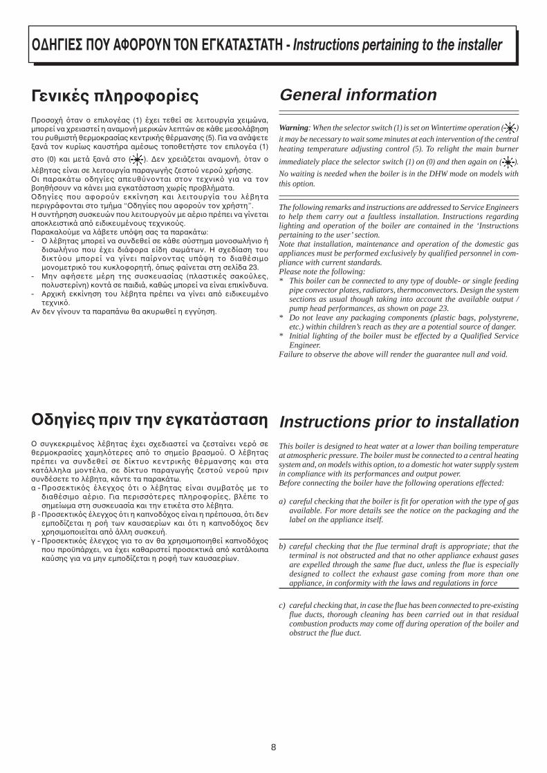
Safety device indicators -activation1 Summer-Winter-Reset selector2 Gas block indicator3 Overheat thermostat has switched on
4 Blocked flue indicator or Flue thermostat has switched on 5 Lack of water or blocked pump indicator6 DHW sensor anomaly indicator7 Central heating sensor anomaly indicator8 Voltage presence indicator9 DHW production mode indicator10 Central heating mode indicator11 Flame presence indicator
Messages 2÷7 display the temperaturereached by the heating system.Operating faults are indicated by aFLASHING display.
As regards message (4), the controlpanel on the boiler will display the
symbol for sealed-chamber forced-flow models, or the symbol fornatural draught models (without fan).
If one of the following faults occurs
( ), turn the selector (1) to
( ) for at least 1 second to restorenormal operating conditions (seefigure 4). In the event that one of the
following faults is displayed ( ),
the message ( ) will be flashed as well.
In the event of message (5), check that the system pressure correspondsto the level specified in the section on page 6.
If safety device activation is repeated contact the authorised TechnicalAssistance Services.
Servicing instructionsTo maintain efficient and safe operation of your boiler have it checked bya Qualified Service Engineer at the end of every operating period.Careful servicing will ensure economical operation of the system.Do not clean the outer casing of the appliance with abrasive, aggressiveand/or easily flammable cleaners (i.e.: gasoline, alcohol, and so on).Always isolate the electrical supply to the appliance before cleaning it(see section Turning off the boiler on page 6).
Figura 4εικνα 4
Λυνίες µηανισµώνασ%αλείας - Ενεργπίηση1. Επιλγέας καλκαίρι - ειµώνας - Reset.2. Λυνία µπλκαρίσµατς αερίυ.3. Θερµστάτης υπερθέρµανσης ανιτς.
4. Λυνία µπλκαρίσµατς , καπνδς ή θερµστάτης καυσαερίων
ανιτς .5. Λυνία έλλειψης νερύ ή µπλκαρίσµατς αντλίας.6. Λυνία αισθητήρα πρλήµατς =εστύ νερύ ρήσης.7. Λυνία αισθητήρα πρλήµατς κεντρικής θέρµανσης.8. Λυνία ηλεκτρικής παρής.9. Λυνία κατάστασης παραγωγής =εστύ νερύ ρήσης.10. Λυνία κατάστασης κεντρικής θέρµανσης.11. Λυνία ένδειCης ύπαρCης %λγας.
Τα µηνύµατα 2-7 δείνυν τηθερµκρασία πυ έει τάσει τσύστηµα. Τα πρ!λήµαταλειτυργίας αίννται απ τ τιη ένδειη ανα!σ!ήνει.
Bσ αρά την ένδειη 4, πίνακας ελέγυ τυ λέ!ητα θα
δείει τ σύµ!λ για
µντέλα !ε!ιασµένης ρήςκαυσαερίων ή τ σύµ!λ για µντέλα υσικής ρής(ωρίς ανεµιστήρα).
Σε περίπτωση εµάνισης µιας εκτων παρακάτω ανωµαλιών
( ) µπρείτε να
απκαταστήσετε τις καννικές συνθήκες λειτυργίας τπθετώνταςεπί 1 τυλάιστν δευτερλεπτ τν επιλγέα (1) στη θέση ( ) (!λ.εικ. 4).Στην περίπτωση πυ υπάρει ένδειη για µια απ τις παρακάτω
!λά!ες ( ) θα ανα!σ!ήνει και τ ( ) .
Στην περίπτωση τυ (5), ελέγτε τι η πίεση τυ συστήµατςανταπκρίνεται στα επίπεδα πυ αναέρνται στην αρή της σελίδας 6.
δηγίες ΣυντήρησηςΓια να έετε απδτική και ασαλή λειτυργία τυ λέ!ητά σας, πρέπεινα τν ελέγει µετά τ τέλς κάθε περιδυ ειδικς τενικς.Πρσεκτική συντήρησης θα εασαλίσει ικνµική λειτυργία. Μηνκαθαρίετε τ εωτερικ µε καθαριστικά πυ µπρύν ναπρκαλέσυν γδαρσίµατα ή θρά (π.. !ενίνη, ινπνευµα κ.λ.π.).Πάντα να κλείνετε τ ρεύµα πριν καθαρίσετε τη µνάδα (!λέπε τντερµατισµ λειτυργίας στη σελ. 6).
0010230400
8
General information
Warning: When the selector switch (1) is set on Wintertime operation ( )
it may be necessary to wait some minutes at each intervention of the centralheating temperature adjusting control (5). To relight the main burner
immediately place the selector switch (1) on (0) and then again on ( ).
No waiting is needed when the boiler is in the DHW mode on models withthis option.
The following remarks and instructions are addressed to Service Engineersto help them carry out a faultless installation. Instructions regardinglighting and operation of the boiler are contained in the ‘Instructionspertaining to the user’ section.Note that installation, maintenance and operation of the domestic gasappliances must be performed exclusively by qualified personnel in com-pliance with current standards.Please note the following:* This boiler can be connected to any type of double- or single feeding
pipe convector plates, radiators, thermoconvectors. Design the systemsections as usual though taking into account the available output /pump head performances, as shown on page 23.
* Do not leave any packaging components (plastic bags, polystyrene,etc.) within children’s reach as they are a potential source of danger.
* Initial lighting of the boiler must be effected by a Qualified ServiceEngineer.
Failure to observe the above will render the guarantee null and void.
Instructions prior to installationThis boiler is designed to heat water at a lower than boiling temperatureat atmospheric pressure. The boiler must be connected to a central heatingsystem and, on models withis option, to a domestic hot water supply systemin compliance with its performances and output power.Before connecting the boiler have the following operations effected:
a) careful checking that the boiler is fit for operation with the type of gasavailable. For more details see the notice on the packaging and thelabel on the appliance itself.
b) careful checking that the flue terminal draft is appropriate; that theterminal is not obstructed and that no other appliance exhaust gasesare expelled through the same flue duct, unless the flue is especiallydesigned to collect the exhaust gase coming from more than oneappliance, in conformity with the laws and regulations in force
c) careful checking that, in case the flue has been connected to pre-existingflue ducts, thorough cleaning has been carried out in that residualcombustion products may come off during operation of the boiler andobstruct the flue duct.
∆ΗΓΙΕΣ ΠΥ ΑΦΡΥΝ ΤΝ ΕΓΚΑΤΑΣΤΑΤΗ - Instructions pertaining to the installer
Γενικές πληρ%ρίεςΠρσή ταν επιλγέας (1) έει τεθεί σε λειτυργία ειµώνα,µπρεί να ρειαστεί η αναµνή µερικών λεπτών σε κάθε µεσλά!ησητυ ρυθµιστή θερµκρασίας κεντρικής θέρµανσης (5). Για να ανάψετεανά τν κυρίως καυστήρα αµέσως τπθετήστε τν επιλγέα (1)
στ (0) και µετά ανά στ ( ). ∆εν ρειάεται αναµνή, ταν
λέ!ητας είναι σε λειτυργία παραγωγής εστύ νερύ ρήσης.%ι παρακάτω δηγίες απευθύννται στν τενικ για να τν!ηθήσυν να κάνει µια εγκατάσταση ωρίς πρ!λήµατα.%δηγίες πυ αρύν εκκίνηση και λειτυργία τυ λέ!ηταπεριγράνται στ τµήµα “%δηγίες πυ αρύν τν ρήστη”.Η συντήρηση συσκευών πυ λειτυργύν µε αέρι πρέπει να γίνεταιαπκλειστικά απ ειδικευµένυς τενικύς.Παρακαλύµε να λά!ετε υπψη σας τα παρακάτω:- % λέ!ητας µπρεί να συνδεθεί σε κάθε σύστηµα µνσωλήνι ή
δισωλήνι πυ έει διάρα είδη σωµάτων. Η σεδίαση τυδικτύυ µπρεί να γίνει παίρνντας υπψη τ διαθέσιµµνµετρικ τυ κυκλρητή, πως αίνεται στη σελίδα 23.
- Μην αήσετε µέρη της συσκευασίας (πλαστικές σακύλες,πλυστερίνη) κντά σε παιδιά, καθώς µπρεί να είναι επικίνδυνα.
- Αρική εκκίνηση τυ λέ!ητα πρέπει να γίνει απ ειδικευµέντενικ.
Αν δεν γίνυν τα παραπάνω θα ακυρωθεί η εγγύηση.
δηγίες πριν την εγκατάσταση% συγκεκριµένς λέ!ητας έει σεδιαστεί να εσταίνει νερ σεθερµκρασίες αµηλτερες απ τ σηµεί !ρασµύ. % λέ!ηταςπρέπει να συνδεθεί σε δίκτυ κεντρικής θέρµανσης και στακατάλληλα µντέλα, σε δίκτυ παραγωγής εστύ νερύ πρινσυνδέσετε τ λέ!ητα, κάντε τα παρακάτω.α - Πρσεκτικς έλεγς τι λέ!ητας είναι συµ!ατς µε τ
διαθέσιµ αέρι. Για περισστερες πληρρίες, !λέπε τσηµείωµα στη συσκευασία και την ετικέτα στ λέ!ητα.
! - Πρσεκτικς έλεγς τι η καπνδς είναι η πρέπυσα, τι δενεµπδίεται η ρή των καυσαερίων και τι η καπνδς δενρησιµπιείται απ άλλη συσκευή.
γ - Πρσεκτικς έλεγς για τ αν θα ρησιµπιηθεί καπνδςπυ πρϋπάρει, να έει καθαριστεί πρσεκτικά απ κατάλιπακαύσης για να µην εµπδίεται η ρή των καυσαερίων.
9
Για να εασαλιστεί η σωστή λειτυργία της συσκευής και για ναµην ακυρωθεί η εγγύηση, τηρήστε τις ακλυθες πρυλάεις
1. Κύκλωµα εστύ νερύ:εάν η σκληρτητα τυ νερύ είναι µεγαλύτερη απ 20 °F (1 °F = 10mg ανθρακικύ ασ!εστίυ ανά λίτρ νερύ) εγκαταστήστε ένασύστηµα !ελτιωτικής επεεργασίας νερύ µε λειτυργίαπλυωσρικών αλάτων ή παρεµερές, σε συµµρωση µε τιςισύυσες διατάεις.
2. Κύκλωµα θέρµανσης2.1. σε καινύργι σύστηµα
Πριν πρωρήσετε στην εγκατάσταση τυ λέ!ητα, τ σύστηµαθα πρέπει να καθαριστεί και να αππλύθεί πλύ καλά, πρκειµένυνα απµακρυνθύν εντελώς τυν άρηστα ρινίσµατα απ τηδιάνιη σπειρωµάτων, θραύσµατα συγκλλήσεων και διαλύτες,ε σν υπάρυν, ρησιµπιώντας κατάλληλα δικά σαςπρϊντα.
2.2. στ υπάρν σύστηµα:Πριν πρωρήσετε στην εγκατάσταση τυ λέ!ητα, τ σύστηµαθα πρέπει να καθαριστεί και να αππλυθεί, πρκειµένυ νααπµακρυνθύν λασπνερα και ρύπι, ρησιµπιώνταςκατάλληλα δικά σας πρϊντα.
Για την απυγή καταστρής των µεταλλικών, πλαστικών καιελαστικών µερών, να ρησιµπιείτε µν υδέτερα καθαριστικά,δηλαδή µη-ινα και µη-αλκαλικά (π.. SENTINEL X400 και X100), καιθα πρέπει να εργαστείτε µε αυστηρή συµµρωση πρς τις δηγίεςτυ κατασκευαστή.
Να θυµάστε τι η παρυσία ένων σωµάτων στ σύστηµα θέρµανσηςµπρεί να επηρεάσει δυσµενώς τη λειτυργία τυ λέ!ητα (π..υπερθέρµανση και θρυ!ώδης λειτυργία τυ εναλλάκτηθερµτητας)
To ensure correct operation of the appliance and avoid invalidating theguarantee, observe the following precautions
1. Hot water circuit:if the water hardness is greater than 20 °F (1 °F = 10 mg calcium carbonateper litre of water) install a polyphosphate or comparable treatment systemresponding to current regulations.
2. Heating circuit2.1. new system
Before proceeding with installation of the boiler, the system must becleaned and flushed out thoroughly to eliminate residual thread-cutting swarf, solder and solvents if any, using suitable proprietaryproducts.
2.2. existing system:Before proceeding with installation of the boiler, the system must becleaned and flushed out to remove sludge and contaminants, usingsuitable proprietary products.
To avoid damaging metal, plastic and rubber parts, use only neutralcleaners, i.e. non-acid and non-alkaline (e.g. SENTINEL X400 and X100),proceeding strictly in accordance with the maker’s directions.
Remember that the presence of foreign matter in the heating system canadversely affect the operation of the boiler (e.g. overheating and noisyoperation of the heat exchanger).
10
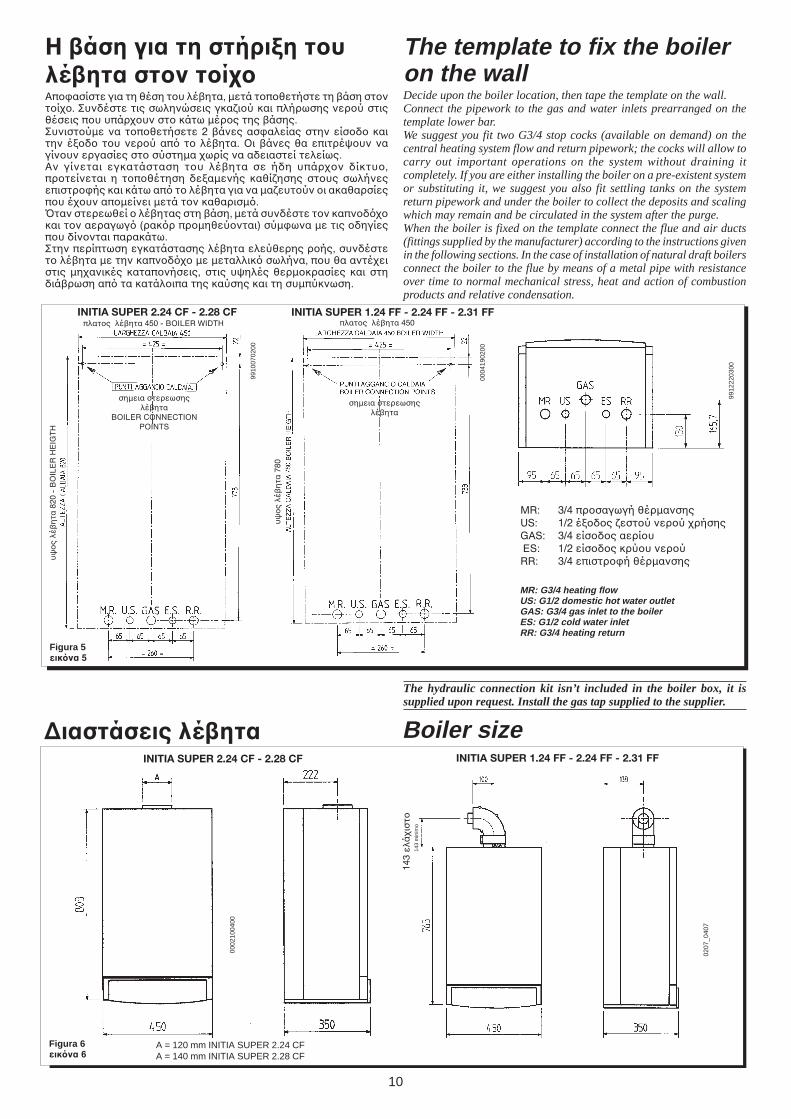
The template to fix the boileron the wallDecide upon the boiler location, then tape the template on the wall.Connect the pipework to the gas and water inlets prearranged on thetemplate lower bar.We suggest you fit two G3/4 stop cocks (available on demand) on thecentral heating system flow and return pipework; the cocks will allow tocarry out important operations on the system without draining itcompletely. If you are either installing the boiler on a pre-existent systemor substituting it, we suggest you also fit settling tanks on the systemreturn pipework and under the boiler to collect the deposits and scalingwhich may remain and be circulated in the system after the purge.When the boiler is fixed on the template connect the flue and air ducts(fittings supplied by the manufacturer) according to the instructions givenin the following sections. In the case of installation of natural draft boilersconnect the boiler to the flue by means of a metal pipe with resistanceover time to normal mechanical stress, heat and action of combustionproducts and relative condensation.
0004
1902
00
Figura 5εικνα 5
MR: G3/4 heating flowUS: G1/2 domestic hot water outletGAS: G3/4 gas inlet to the boilerES: G1/2 cold water inletRR: G3/4 heating return
Figura 6εικνα 6
9912
2203
00Boiler size∆ιαστάσεις λέητα
Η άση για τη στήριCη τυλέητα στν τίΑπασίστε για τη θέση τυ λέ!ητα, µετά τπθετήστε τη !άση στντί. Συνδέστε τις σωληνώσεις γκαιύ και πλήρωσης νερύ στιςθέσεις πυ υπάρυν στ κάτω µέρς της !άσης.Συνιστύµε να τπθετήσετε 2 !άνες ασαλείας στην είσδ καιτην έδ τυ νερύ απ τ λέ!ητα. %ι !άνες θα επιτρέψυν ναγίνυν εργασίες στ σύστηµα ωρίς να αδειαστεί τελείως.Αν γίνεται εγκατάσταση τυ λέ!ητα σε ήδη υπάρν δίκτυ,πρτείνεται η τπθέτηση δεαµενής καθίησης στυς σωλήνεςεπιστρής και κάτω απ τ λέ!ητα για να µαευτύν ι ακαθαρσίεςπυ έυν απµείνει µετά τν καθαρισµ.Bταν στερεωθεί λέ!ητας στη !άση, µετά συνδέστε τν καπνδκαι τν αεραγωγ (ρακρ πρµηθεύνται) σύµωνα µε τις δηγίεςπυ δίννται παρακάτω.Στην περίπτωση εγκατάστασης λέ!ητα ελεύθερης ρής, συνδέστετ λέ!ητα µε την καπνδ µε µεταλλικ σωλήνα, πυ θα αντέειστις µηανικές καταπνήσεις, στις υψηλές θερµκρασίες και στηδιά!ρωση απ τα κατάλιπα της καύσης και τη συµπύκνωση.
0207
_040
7
143
min
imo
ΜR: 3/4 πρσαγωγή θέρµανσηςUS: 1/2 έδς εστύ νερύ ρήσηςGAS: 3/4 είσδς αερίυ ES: 1/2 είσδς κρύυ νερύRR: 3/4 επιστρή θέρµανσης
πλατς λέ!ητα 450
υψ
ς
λέ!
ητα
780
σηµεια στερεωσηςλέ!ητα
9910
0702
00
πλατς λέ!ητα 450 - BOILER WIDTH
σηµεια στερεωσηςλέ!ητα
BOILER CONNECTIONPOINTS
υψ
ς
λέ!
ητα
820
- B
OIL
ER
HE
IGT
H
INITIA SUPER 2.24 CF - 2.28 CF INITIA SUPER 1.24 FF - 2.24 FF - 2.31 FF
INITIA SUPER 1.24 FF - 2.24 FF - 2.31 FF
0002
1004
00
INITIA SUPER 2.24 CF - 2.28 CF
A = 120 mm INITIA SUPER 2.24 CFA = 140 mm INITIA SUPER 2.28 CF
143
ελά
ισ
τ
The hydraulic connection kit isn’t included in the boiler box, it issupplied upon request. Install the gas tap supplied to the supplier.
11
Flue duct terminal
CoaxialVertical two-pipe
Horizontal two-pipe
Outerduct
diameter
100 mm80 mm80 mm
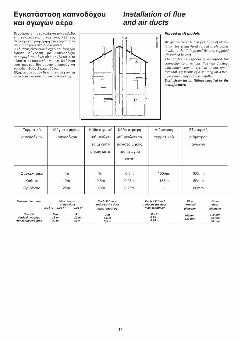
Installation of flueand air ducts
Forced draft models
We guarantee ease and flexibility of instal-lation for a gas-fired forced draft boilerthanks to the fittings and fixtures supplied(described below).The boiler is especially designed forconnection to an exhaust flue / air ducting,with either coaxial, vertical or horizontalterminal. By means of a splitting kit a two-pipe system may also be installed.Exclusively install fittings supplied by themanufacturer.
Max. lengthof flue duct
1.24 FF - 2.24 FF 2.31 FF
5 m 4 m15 m 12 m40 m 25 m
Each 90° bendreduces the ductmax. length by
1 m0,5 m0,5 m
Each 45° bendreduces the ductmax. length by
0,5 m0,25 m0,25 m
Flueterminaldiameter
100 mm133 mm
-
Εγκατάσταση καπνδυκαι αγωγών αέραΕγγυµαστε την ευκλία και την ευελιίατης εγκατάστασης για τυς λέ!ητες!ε!ιασµένης ρής άρη στα εαρτήµαταπυ υπάρυν στη συσκευασία.% λέ!ητας είναι ειδικά σεδιασµένς γιαάµεση σύνδεση µε καπνδ/αεραγωγ πυ έει είτε ριντι, είτεκάθετ τερµατικ. Με τη !ήθειασυστήµατς διαίρεσης µπρύν νατπθετηθύν 2 καπνδι.Εαρτήµατα σύνδεσης παρένταιαπκλειστικά απ τν κατασκευαστή.
9912
2207
00
Τερµατικά Μέγιστ µήκς Κάθε στρή Κάθε στρή ∆ιάµετρς Εωτερική
καπνδων: καπνδυ 90° µειώνει 45° µειώνει τ τερµατικύ διάµετρς
τ µέγιστ µέγιστ µήκς αγωγύ
µήκς κατά: τυ αγωγύ
κατά:
Oµκεντρικά 4m 1m 0,5m 100mm 100mm
Κάθετα 12m 0,5m 0,25m 133m 80mm
%ριντια 25m 0,5m 0,25m - 80mm
12
επιλγές εγκατάστασης ρι=ντιας καµινάδας
L max = 5 m 2.24 FF - 1.24 FFL max = 4 m 2.31 FF L max = 5 m 2.24 FF - 1.24 FF
L max = 4 m 2.31 FF
L max = 4 m 2.24 FF - 1.24 FFL max = 3 m 2.31 FF
L max = 4 m 2.24 FF - 1.24 FFL max = 3 m 2.31 FF
L max = 5 m 2.24 FF - 1.24 FFL max = 4 m 2.31 FF
LAS flue duct installation optionsεπιλγές εγκατάστασης καπνδυ LAS
0002
2304
00
9912
2209
00
9405030830
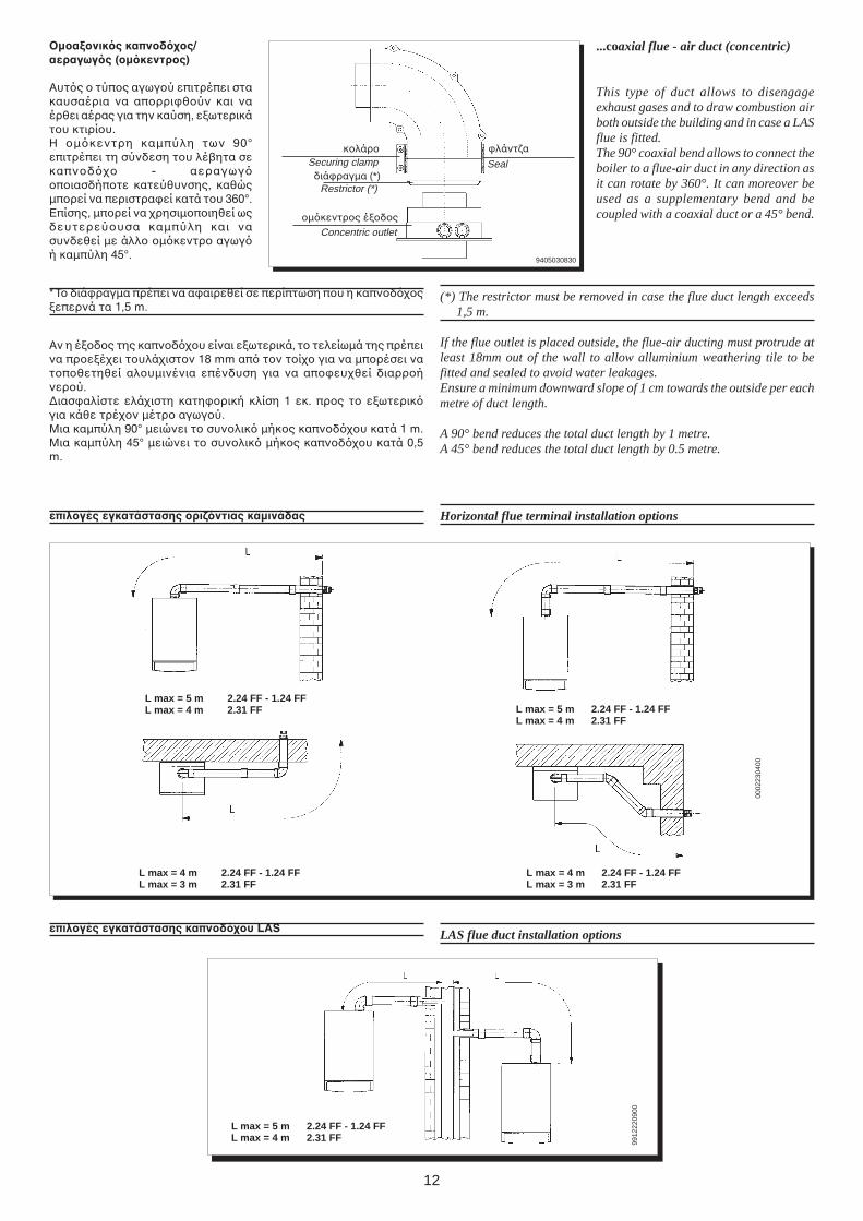
...coaxial flue - air duct (concentric)
This type of duct allows to disengageexhaust gases and to draw combustion airboth outside the building and in case a LASflue is fitted.The 90° coaxial bend allows to connect theboiler to a flue-air duct in any direction asit can rotate by 360°. It can moreover beused as a supplementary bend and becoupled with a coaxial duct or a 45° bend.
(*) The restrictor must be removed in case the flue duct length exceeds1,5 m.
If the flue outlet is placed outside, the flue-air ducting must protrude atleast 18mm out of the wall to allow alluminium weathering tile to befitted and sealed to avoid water leakages.Ensure a minimum downward slope of 1 cm towards the outside per eachmetre of duct length.
A 90° bend reduces the total duct length by 1 metre.A 45° bend reduces the total duct length by 0.5 metre.
Horizontal flue terminal installation options
µαCνικς καπνδς/αεραγωγς (µκεντρς)
Αυτς τύπς αγωγύ επιτρέπει στακαυσαέρια να απρριθύν και ναέρθει αέρας για την καύση, εωτερικάτυ κτιρίυ.Η µκεντρη καµπύλη των 90°επιτρέπει τη σύνδεση τυ λέ!ητα σεκαπνδ - αεραγωγπιασδήπτε κατεύθυνσης, καθώςµπρεί να περιστραεί κατά τυ 360°.Επίσης, µπρεί να ρησιµπιηθεί ωςδευτερεύυσα καµπύλη και νασυνδεθεί µε άλλ µκεντρ αγωγή καµπύλη 45°.
* Τ διάραγµα πρέπει να ααιρεθεί σε περίπτωση πυ η καπνδςεπερνά τα 1,5 m.
Αν η έδς της καπνδυ είναι εωτερικά, τ τελείωµά της πρέπεινα πρεέει τυλάιστν 18 mm απ τν τί για να µπρέσει νατπθετηθεί αλυµινένια επένδυση για να απευθεί διαρρήνερύ.∆ιασαλίστε ελάιστη κατηρική κλίση 1 εκ. πρς τ εωτερικγια κάθε τρέν µέτρ αγωγύ.Μια καµπύλη 90° µειώνει τ συνλικ µήκς καπνδυ κατά 1 m.Μια καµπύλη 45° µειώνει τ συνλικ µήκς καπνδυ κατά 0,5m.
Securing clamp
Restrictor (*)
Concentric outlet
Seal
κλάρ λάντα
διάραγµα (*)
µκεντρς έδς
13
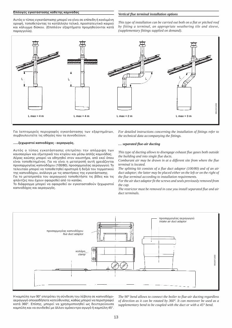
L max = 4 m L max = 4 m L max = 3 mL max = 2 m
Vertical flue terminal installation options
This type of installation can be carried out both on a flat or pitched roofby fitting a terminal, an appropriate weathering tile and sleeve,(supplementary fittings supplied on demand).
Επιλγές εγκατάστασης κάθετης καµινάδας
Αυτς τύπς εγκατάστασης µπρεί να γίνει σε επίπεδη ή κεκλιµένηρή, τπθετώντας τ κατάλληλ τελικ, πρστατευτικ καιρύκαι κάλυµµα δίσκυ. (Επιπλέν εαρτήµατα πρµηθεύνται κατάπαραγγελία).
For detailed instructions concerning the installation of fittings refer tothe technical data accompanying the fittings.
… separated flue-air ducting
This type of ducting allows to disengage exhaust flue gases both outsidethe building and into single flue ducts.Comburant air may be drawn in at a different site from where the flueterminal is located.The splitting kit consists of a flue duct adaptor (100/80) and of an airduct adaptor; the latter may be placed either on the left or on the right ofthe flue terminal according to installation requirements.For the air duct adaptor fit the screws and seals previously removed fromthe cap.The restrictor must be removed in case you install separated flue and airduct terminals.
πρσαρµγέας αεραγωγύIntake air duct adaptor
πρσαρµγέας καπνδυflue duct adaptor
κλάρ clamp
Η καµπύλη των 90° επιτρέπει τη σύνδεση τυ λέ!ητα σε καπνδ-αεραγωγ πιασδήπτε κατεύθυνσης, καθώς µπρεί να περιστραείκατά 360°. Επίσης, µπρεί να ρησιµπιηθεί ως δευτερεύυσακαµπύλη και να συνδεθεί µε άλλν µκεντρ αγωγ ή καµπύλη 45°.
The 90° bend allows to connect the boiler to flue-air ducting regardlessof direction as it can be rotated by 360°. It can moreover be used as asupplementary bend to be coupled with the duct or with a 45° bend.
9912
2210
0099
1007
1000
Για λεπτµερείς περιγραές εγκατάστασης των εαρτηµάτων,συµ!υλευτείτε τις δηγίες πυ τα συνδεύυν.
......Cεωριστί καπνδς - αεραγωγς.
Αυτς τύπς εγκατάστασης επιτρέπει την απρριψη τωνκαυσαερίων και εωτερικά τυ κτιρίυ και µέσω απλής καµινάδας.Αέρας καύσης µπρεί να δηγηθεί στν καυστήρα, απ εκεί πυείναι τπθετηµένς. Για να γίνει η µετατρπή αυτή ρειάνταιπρσαρµγέας καπνδυ (100/80), πρσαρµγέας αεραγωγύ. Ττελευταί µπρεί να τπθετηθεί αριστερά ή δειά τυ τερµατικύτης καπνδυ, ανάλγα µε τις απαιτήσεις της εγκατάστασης.Για τ µετατρπέα τυ αεραγωγύ τπθετήστε τις !ίδες και τιςλάντες πυ έυν ααιρεθεί απ τ καπάκι.Τ διάραγµα µπρεί να ααιρεθεί αν εγκατασταθύν εωριστίκαπνδς και αεραγωγς.
14
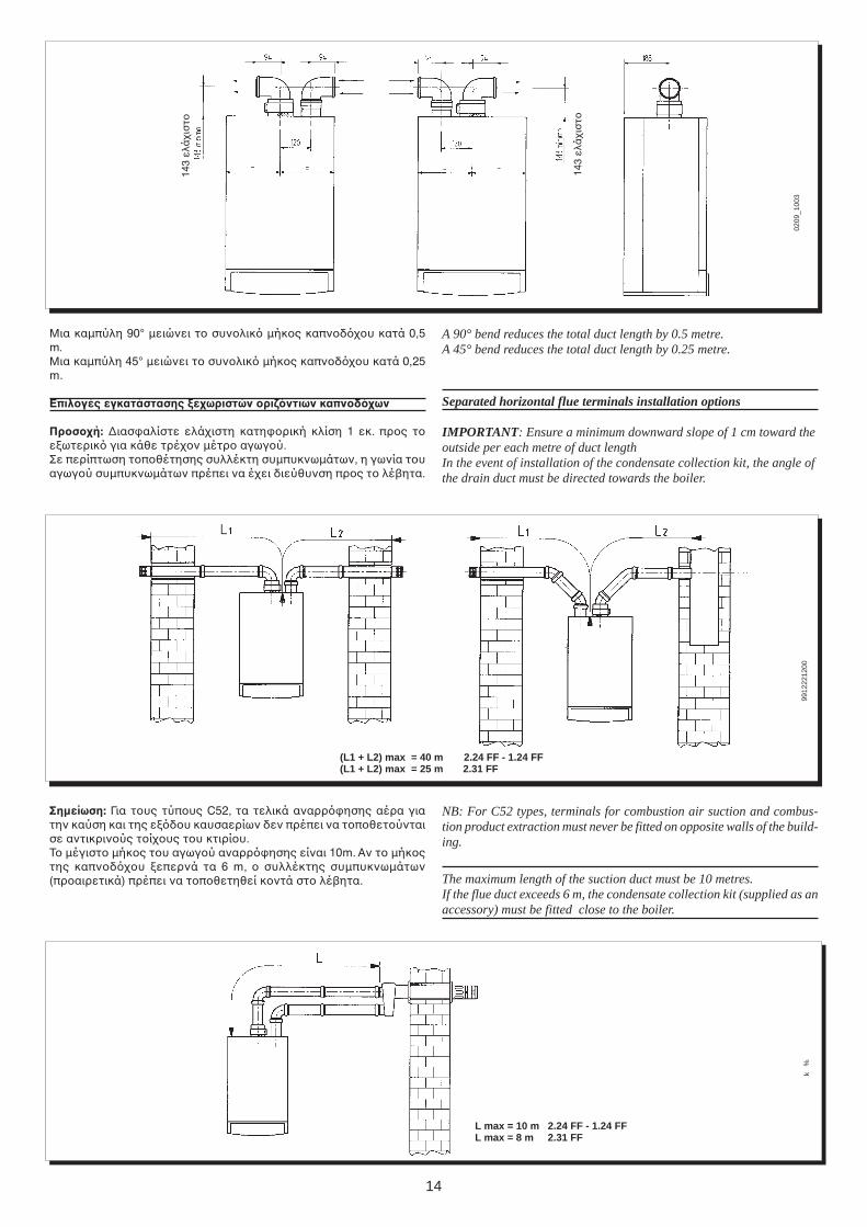
(L1 + L2) max = 40 m 2.24 FF - 1.24 FF(L1 + L2) max = 25 m 2.31 FF
A 90° bend reduces the total duct length by 0.5 metre.A 45° bend reduces the total duct length by 0.25 metre.
Separated horizontal flue terminals installation options
IMPORTANT: Ensure a minimum downward slope of 1 cm toward theoutside per each metre of duct lengthIn the event of installation of the condensate collection kit, the angle ofthe drain duct must be directed towards the boiler.
Μια καµπύλη 90° µειώνει τ συνλικ µήκς καπνδυ κατά 0,5m.Μια καµπύλη 45° µειώνει τ συνλικ µήκς καπνδυ κατά 0,25m.
Επιλγές εγκατάστασης Cεωριστών ρι=ντιων καπνδων
Πρσή: ∆ιασαλίστε ελάιστη κατηρική κλίση 1 εκ. πρς τεωτερικ για κάθε τρέν µέτρ αγωγύ.Σε περίπτωση τπθέτησης συλλέκτη συµπυκνωµάτων, η γωνία τυαγωγύ συµπυκνωµάτων πρέπει να έει διεύθυνση πρς τ λέ!ητα.
L max = 10 m 2.24 FF - 1.24 FFL max = 8 m 2.31 FF
0209
_100
399
1222
1200
k%
Σηµείωση: Για τυς τύπυς C52, τα τελικά αναρρησης αέρα γιατην καύση και της εδυ καυσαερίων δεν πρέπει να τπθετύνταισε αντικρινύς τίυς τυ κτιρίυ.Τ µέγιστ µήκς τυ αγωγύ αναρρησης είναι 10m. Αν τ µήκςτης καπνδυ επερνά τα 6 m, συλλέκτης συµπυκνωµάτων(πραιρετικά) πρέπει να τπθετηθεί κντά στ λέ!ητα.
NB: For C52 types, terminals for combustion air suction and combus-tion product extraction must never be fitted on opposite walls of the build-ing.
The maximum length of the suction duct must be 10 metres.If the flue duct exceeds 6 m, the condensate collection kit (supplied as anaccessory) must be fitted close to the boiler.
143
ελά
ισ
τ
143
ελά
ισ
τ
15
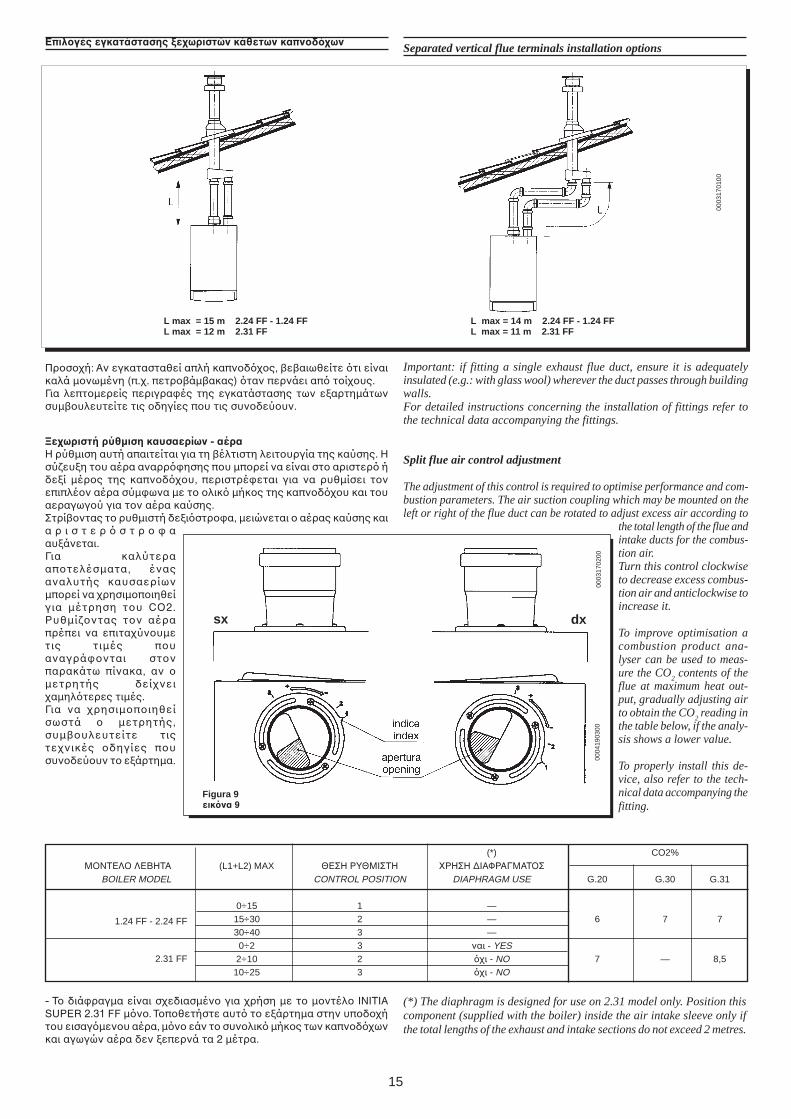
L max = 14 m 2.24 FF - 1.24 FFL max = 11 m 2.31 FF
L max = 15 m 2.24 FF - 1.24 FFL max = 12 m 2.31 FF
Separated vertical flue terminals installation optionsΕπιλγές εγκατάστασης Cεωριστών κάθετων καπνδων
Important: if fitting a single exhaust flue duct, ensure it is adequatelyinsulated (e.g.: with glass wool) wherever the duct passes through buildingwalls.For detailed instructions concerning the installation of fittings refer tothe technical data accompanying the fittings.
Split flue air control adjustment
The adjustment of this control is required to optimise performance and com-bustion parameters. The air suction coupling which may be mounted on theleft or right of the flue duct can be rotated to adjust excess air according to
the total length of the flue andintake ducts for the combus-tion air.Turn this control clockwiseto decrease excess combus-tion air and anticlockwise toincrease it.
To improve optimisation acombustion product ana-lyser can be used to meas-ure the CO
2 contents of the
flue at maximum heat out-put, gradually adjusting airto obtain the CO
2 reading in
the table below, if the analy-sis shows a lower value.
To properly install this de-vice, also refer to the tech-nical data accompanying thefitting.
0003
1701
00
0003
1702
00
Figura 9εικνα 9
sx dx
0004
1903
00
(*) CO2%Μ%ΝΤΕΛ% ΛΕΒΗΤΑ (L1+L2) MAX ΘΕΣΗ ΡΥΘΜΙΣΤΗ _ΡΗΣΗ ∆ΙΑΦΡΑΓΜΑΤ%Σ
BOILER MODEL CONTROL POSITION DIAPHRAGM USE G.20 G.30 G.31
0÷15 1 —15÷30 2 — 6 7 730÷40 3 —0÷2 3 ναι - YES2÷10 2 ι - NO 7 — 8,5
10÷25 3 ι - NO
- Τ διάραγµα είναι σεδιασµέν για ρήση µε τ µντέλ INITIASUPER 2.31 FF µν. Τπθετήστε αυτ τ εάρτηµα στην υπδήτυ εισαγµενυ αέρα, µν εάν τ συνλικ µήκς των καπνδωνκαι αγωγών αέρα δεν επερνά τα 2 µέτρα.
(*) The diaphragm is designed for use on 2.31 model only. Position thiscomponent (supplied with the boiler) inside the air intake sleeve only ifthe total lengths of the exhaust and intake sections do not exceed 2 metres.
2.31 FF
1.24 FF - 2.24 FF
Πρσή: Αν εγκατασταθεί απλή καπνδς, !ε!αιωθείτε τι είναικαλά µνωµένη (π.. πετρ!άµ!ακας) ταν περνάει απ τίυς.Για λεπτµερείς περιγραές της εγκατάστασης των εαρτηµάτωνσυµ!υλευτείτε τις δηγίες πυ τις συνδεύυν.
Mεωριστή ρύθµιση καυσαερίων - αέραΗ ρύθµιση αυτή απαιτείται για τη !έλτιστη λειτυργία της καύσης. Ησύευη τυ αέρα αναρρησης πυ µπρεί να είναι στ αριστερ ήδεί µέρς της καπνδυ, περιστρέεται για να ρυθµίσει τνεπιπλέν αέρα σύµωνα µε τ λικ µήκς της καπνδυ και τυαεραγωγύ για τν αέρα καύσης.Στρί!ντας τ ρυθµιστή δειστρα, µειώνεται αέρας καύσης καια ρ ι σ τ ε ρ σ τ ρ ααυάνεται.Για καλύτερααπτελέσµατα, έναςαναλυτής καυσαερίωνµπρεί να ρησιµπιηθείγια µέτρηση τυ CO2.Ρυθµίντας τν αέραπρέπει να επιταύνυµετις τιµές πυαναγράνται στνπαρακάτω πίνακα, αν µετρητής δείνειαµηλτερες τιµές.Για να ρησιµπιηθείσωστά µετρητής,συµ!υλευτείτε τιςτενικές δηγίες πυσυνδεύυν τ εάρτηµα.
16
Figura 11εικνα 11
9402
2507
15
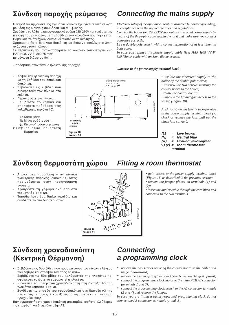
Σύνδεση παρής ρεύµατςΗ ασάλεια της συσκευής εγγυάται µν αν έει γίνει σωστή γείωσηµε !άση τις διεθνείς συµ!άσεις και συµωνίες.Συνδέστε τ λέ!ητα σε µνασικ ρεύµα 220-230V και γειώστε τηνπαρή τυ ρεύµατς µε τη !ήθεια τυ καλωδίυ πυ παρέεται.Βε!αιωθείτε τι έυν συνδεθεί σωστά ι πλικτητες._ρησιµπιήστε διπλικ διακπτη µε διάκεν τυλάιστ 3mmανάµεσα στυς πλυς.Σε περίπτωση πυ αντικαταστήσετε τ καλώδι, τπθετήστε έναHAR HOS VV-F’ 3x0,75 mm2
µε µέγιστη διάµετρ 8mm.
...πρσ!αση στν πίνακα ηλεκτρικής παρής.
- Κψτε την ηλεκτρική παρήµε τη !ήθεια τυ διπλικύδιακπτη.
- dε!ιδώστε τις 2 !ίδες πυσυγκρατύν τν πίνακα στλέ!ητα.
- Περιστρέψτε τν πίνακα.- dε!ιδώστε τ καπάκι και
απκτήστε πρσ!αση στιςκαλωδιώσεις (εικνα 10).
L: Καέ άσηN: Μπλε υδέτερς
: Κίτριν/πράσιν γείωση(1), (2): Τερµατικ θερµστάτη
δωµατίυ Figura 10εικνα 10
Connecting the mains supplyElectrical safety of the appliance is only guaranteed by correct grounding,in compliance with the applicable laws and regulations.Connect the boiler to a 220-230V monophase + ground power supply bymeans of the three-pin cable supplied with it and make sure you connectpolarities correctly.Use a double-pole switch with a contact separation of at least 3mm inboth poles.In case you replace the power supply cable fit a HAR H05 VV-F’3x0.75mm2 cable with an 8mm diameter max.
…access to the power supply terminal block
• isolate the electrical supply to theboiler by the double-pole switch;• unscrew the two screws securing thecontrol board to the boiler;• rotate the control board;• unscrew the lid and gain access to thewiring (Figure 10).
A 2A fast-blowing fuse is incorporatedin the power supply terminal block (tocheck or replace the fuse, pull out theblack fuse carrier).
(L) = Live brown(N) = Neutral blue( ) = Ground yellow/green
(1) (2) = room thermostatterminal
0004
1904
00
Fitting a room thermostat• gain access to the power supply terminal block(Figure 11) as described in the previous section;• remove the jumper placed on terminals (1) and(2);• insert the duplex cable through the core hitch andconnect it to the two terminals.
Σύνδεση θερµστάτη ώρυ- Απκτήστε πρσ!αση στν πίνακα
ηλεκτρικής παρής (εικνα 11) πωςπεριγράεται στην πρηγύµενηεντητα.
- Ααιρέστε τη γέυρα ανάµεσα στατερµατικά (1) και (2).
- Τπθετήστε ένα διπλ καλώδι καισυνδέστε τ στα δύ τερµατικά.
Σύνδεση ρνδιακπτη(Κεντρική Θέρµανση)- dε!ιδώστε τις δύ !ίδες πυ πρστατεύυν τν πίνακα ελέγυ
τυ λέ!ητα και στρέψτε τν πρς τα κάτω.- dε!ιδώστε τις δύ !ίδες τυ καλύµµατς της πλακέτας και
ααιρέστε τ ώστε να εµανιστεί η πλακέτα.- Συνδέστε τ µτέρ τυ ρνδιακπτη στη διάταη Α3 της
πλακέτας (επαές 1 και 3).- Συνδέστε τις επαές τυ ρνδιακπτη στη διάταη Α3 της
πλακέτας (επαές 2 και 4) αύ ααιρέσετε τη γέυρα!ραυκύκλωσης.
Εάν εγκαταστήσετε ρνδιακπτη µπαταρίας, αήστε ελεύθερεςτις επαές 1 και 3 της διάταης Α3.
Connectinga programming clock* remove the two screws securing the control board to the boiler and
hinge it downward;* remove the 2 screws fixing the control board cover and hinge it upward;* connect the programming clock motor to the main PCB A3 connector
(terminals 1 and 3);* connect the programming clock switch to the A3 connector terminals
(2 and 4) and remove the jumper.In case you are fitting a battery-operated programming clock do notconnect the A3 connector terminals (1 and 3).
καπάκι
!άση ακρδεκτών
17
Figura 12εικνα 12
Valvola Honeywell valvemod. VK 4105 M
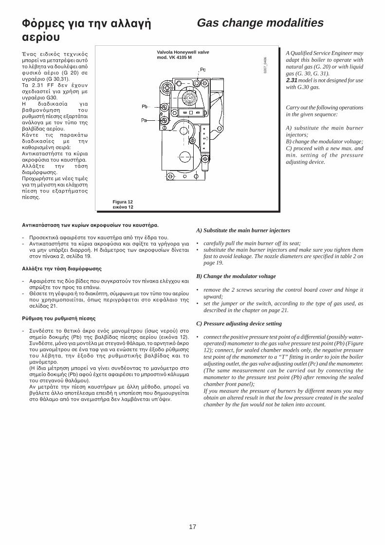
Φρµες για την αλλαγήαερίυΈνας ειδικς τενικςµπρεί να µετατρέψει αυττ λέ!ητα να δυλέψει απυσικ αέρι (G 20) σευγραέρι (G 30,31).Τα 2.31 FF δεν έυνσεδιαστεί για ρήση µευγραέρι G30.Η διαδικασία για!αθµνµηση τυρυθµιστή πίεσης εαρτάταιανάλγα µε τν τύπ της!αλ!ίδας αερίυ.Κάντε τις παρακάτωδιαδικασίες µε τηνκαθρισµένη σειρά:Αντικαταστήστε τα κύριαακρύσια τυ καυστήρα.Αλλάτε την τάσηδιαµρωσης.Πρωρήστε µε νέες τιµέςγια τη µέγιστη και ελάιστηπίεση τυ εαρτήµατςπίεσης.
Αντικατάσταση των κυρίων ακρ%υσίων τυ καυστήρα.
- Πρσεκτικά ααιρέστε τν καυστήρα απ την έδρα τυ.- Αντικαταστήστε τα κύρια ακρύσια και σίτε τα γρήγρα για
να µην υπάρει διαρρή. Η διάµετρς των ακρυσίων δίνεταιστν πίνακα 2, σελίδα 19.
ΑλλάCτε την τάση διαµρ%ωσης
- Ααιρέστε τις δύ !ίδες πυ συγκρατύν τν πίνακα ελέγυ καισπρώτε τν πρς τα επάνω.
- Θέσετε τη γέυρα ή τ διακπτη, σύµωνα µε τν τύπ τυ αερίυπυ ρησιµπιείται, πως περιγράεται στ κεάλαι τηςσελίδας 21.
Ρύθµιση τυ ρυθµιστή πίεσης
- Συνδέστε τ θετικ άκρ ενς µανµέτρυ (ίσως νερύ) στσηµεί δκιµής (Pb) της !αλ!ίδας πίεσης αερίυ (εικνα 12).Συνδέστε, µν για µντέλα µε στεγαν θάλαµ, τ αρνητικ άκρτυ µανµέτρυ σε ένα τα για να ενώσετε την έδ ρύθµισηςτυ λέ!ητα, την έδ της ρυθµιστικής !αλ!ίδας και τµανµετρ.(Η ίδια µέτρηση µπρεί να γίνει συνδέντας τ µανµετρ στσηµεί δκιµής (Pb) αύ έετε ααιρέσει τ µπρστιν κάλυµµατυ στεγανύ θαλάµυ).Αν µετράτε την πίεση καυστήρων µε άλλη µέθδ, µπρεί να!γάλετε άλλ απτέλεσµα επειδή η υππίεση πυ δηµιυργείταιστ θάλαµ απ τν ανεµιστήρα δεν λαµ!άνεται υπ’ψιν.
Gas change modalities
A Qualified Service Engineer mayadapt this boiler to operate withnatural gas (G. 20) or with liquidgas (G. 30, G. 31).2.31 model is not designed for usewith G.30 gas.
Carry out the following operationsin the given sequence:
A) substitute the main burnerinjectors;B) change the modulator voltage;C) proceed with a new max. andmin. setting of the pressureadjusting device.
0207
_040
6
A) Substitute the main burner injectors
• carefully pull the main burner off its seat;• substitute the main burner injectors and make sure you tighten them
fast to avoid leakage. The nozzle diameters are specified in table 2 onpage 19.
B) Change the modulator voltage
• remove the 2 screws securing the control board cover and hinge itupward;
• set the jumper or the switch, according to the type of gas used, asdescribed in the chapter on page 21.
C) Pressure adjusting device setting
• connect the positive pressure test point of a differential (possibly water-operated) manometer to the gas valve pressure test point (Pb) (Figure12); connect, for sealed chamber models only, the negative pressuretest point of the manometer to a “T” fitting in order to join the boileradjusting outlet, the gas valve adjusting outlet (Pc) and the manometer.(The same measurement can be carried out by connecting themanometer to the pressure test point (Pb) after removing the sealedchamber front panel);If you measure the pressure of burners by different means you mayobtain an altered result in that the low pressure created in the sealedchamber by the fan would not be taken into account.
18
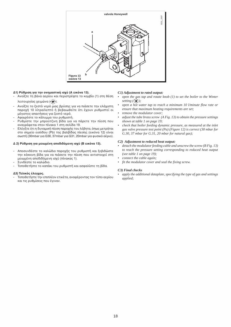
∆1) Ρύθµιση για την νµαστική ισύ (A εικνα 13).- Ανίτε τη !άνα αερίυ και περιστρέψτε τ κµ!ί (1) στη θέση
λειτυργίας ειµώνα ( ).
- Ανίτε τ εστ νερ µιας !ρύσης για να πιάσετε την ελάιστηπαρή 10 λίτρα/λεπτ ή !ε!αιωθείτε τι έυν ρυθµιστεί ιµέγιστες απαιτήσεις για εστ νερ.
- Ααιρέστε τ κάλυµµα τυ ρυθµιστή.- Ρυθµίστε την µπρύτινη !ίδα για να πάρετε την πίεση πυ
αναγράεται στν πίνακα 1 στη σελίδα 19.- Ελέγτε τι η δυναµική πίεση παρής τυ λέ!ητα, πως µετράται
στ σηµεί εισδυ (Pb) της !αλ!ίδας πίεσης (εικνα 12) είναισωστή (30mbar για G30, 37mbar για G31, 20mbar για υσικ αέρι).
∆ 2) Ρύθµιση για µειωµένη απδιδµενη ισύ (B εικνα 13).
- Απσυνδέστε τ καλώδι παρής τυ ρυθµιστή και ε!ιδώστετην κκκινη !ίδα για να πιάσετε την πίεση πυ αντιστιεί στηµειωµένη απδιδµενη ισύ (πίνακας 1).
- Συνδέστε τ καλώδι.- Τπθετήστε τ καπάκι τυ ρυθµιστή και ασαλίστε τη !ίδα.
∆3) Τελικς έλεγς.- Τπθετήστε την επιπλέν ετικέτα, αναέρντας τν τύπ αερίυ
και τις ρυθµίσεις πυ έγιναν.
C1) Adjustment to rated output:• open the gas tap and rotate knob (1) to set the boiler to the Winter
setting ( );• open a hot water tap to reach a minimum 10 l/minute flow rate or
ensure that maximum heating requirements are set;• remove the modulator cover;• adjust the tube brass screw (A Fig. 13) to obtain the pressure settings
shown at table 1 on page 19;• check that boiler feeding dynamic pressure, as measured at the inlet
gas valve pressure test point (Pa) (Figure 12) is correct (30 mbar forG.30, 37 mbar for G.31, 20 mbar for natural gas);
C2) Adjustment to reduced heat output:• detach the modulator feeding cable and unscrew the screw (B Fig. 13)
to reach the pressure setting corresponding to reduced heat output(see table 1 on page 19);
• connect the cable again;• fit the modulator cover and seal the fixing screw.
C3) Final checks• apply the additional dataplate, specifying the type of gas and settings
applied;
b
a
Figura 13εικνα 13
0211
_150
7
valvola Honeywell
19
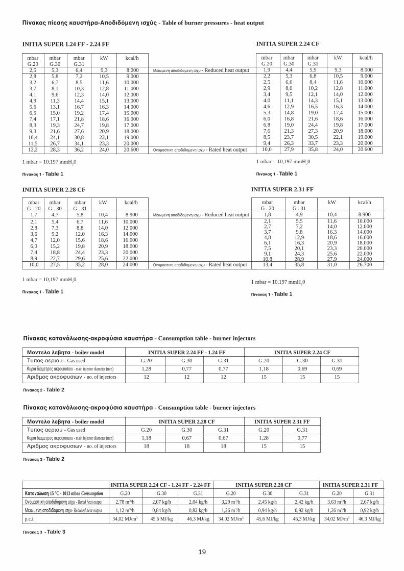
Πίνακας πίεσης καυστήρα-Απδιδµενη ισύς - Table of burner pressures - heat output
INITIA SUPER 1.24 FF - 2.24 FF
mbar mbar mbar kW kcal/hG.20 G.30 G.312,5 5,3 6,4 9,3 8.000 Μειωµενη απδιδµενη ισυ - Reduced heat output2,8 5,8 7,2 10,5 9.0003,2 6,7 8,5 11,6 10.0003,7 8,1 10,3 12,8 11.0004,1 9,6 12,3 14,0 12.0004,9 11,3 14,4 15,1 13.0005,6 13,1 16,7 16,3 14.0006,5 15,0 19,2 17,4 15.0007,4 17,1 21,8 18,6 16.0008,3 19,3 24,7 19,8 17.0009,3 21,6 27,6 20,9 18.00010,4 24,1 30,8 22,1 19.00011,5 26,7 34,1 23,3 20.00012,2 28,3 36,2 24,0 20.600 %νµαστικη απδιδµενη ισυ - Rated heat output
1 mbar = 10,197 mmH20
Πινακας 1 - Table 1
INITIA SUPER 2.24 CF
mbar mbar mbar kW kcal/hG.20 G.30 G.311,9 4,4 5,9 9,3 8.0002,2 5,3 6,8 10,5 9.0002,5 6,6 8,4 11,6 10.0002,9 8,0 10,2 12,8 11.0003,4 9,5 12,1 14,0 12.0004,0 11,1 14,3 15,1 13.0004,6 12,9 16,5 16,3 14.0005,3 14,8 19,0 17,4 15.0006,0 16,8 21,6 18,6 16.0006,8 19,0 24,4 19,8 17.0007,6 21,3 27,3 20,9 18.0008,5 23,7 30,5 22,1 19.0009,4 26,3 33,7 23,3 20.00010,0 27,9 35,8 24,0 20.600
1 mbar = 10,197 mmH20
Πινακας 1 - Table 1
Πίνακας κατανάλωσης-ακρ%ύσια καυστήρα - Consumption table - burner injectors
Μντελ λεητα - boiler model INITIA SUPER 2.24 FF - 1.24 FF INITIA SUPER 2.24 CF
Τυπς αεριυ - Gas used G.20 G.30 G.31 G.20 G.30 G.31
Κυρια διαµετρς ακρυσιυ - main injector diameter (mm) 1,28 0,77 0,77 1,18 0,69 0,69
Αριθµς ακρυσιων - no. of injectors 12 12 12 15 15 15
Πινακας 2 - Table 2
INITIA SUPER 2.24 CF - 1.24 FF - 2.24 FF INITIA SUPER 2.28 CF INITIA SUPER 2.31 FF
Καταναλωση 15 °C - 1013 mbar Consumption G.20 G.30 G.31 G.20 G.30 G.31 G.20 G.31
%νµαστικη απδιδµενη ισυ - Rated heat output 2,78 m3/h 2,07 kg/h 2,04 kg/h 3,29 m3/h 2,45 kg/h 2,42 kg/h 3,63 m3/h 2,67 kg/h
Μειωµενη απδιδµενη ισυ- Reduced heat output 1,12 m3/h 0,84 kg/h 0,82 kg/h 1,26 m3/h 0,94 kg/h 0,92 kg/h 1,26 m3/h 0,92 kg/h
p.c.i. 34,02 MJ/m3 45,6 MJ/kg 46,3 MJ/kg 34,02 MJ/m3 45,6 MJ/kg 46,3 MJ/kg 34,02 MJ/m3 46,3 MJ/kg
Πινακας 3 - Table 3
INITIA SUPER 2.28 CF
mbar mbar mbar kW kcal/hG . 20 G . 30 G . 31
1,7 4,7 5,8 10,4 8.900 Μειωµενη απδιδµενη ισυ - Reduced heat output2,1 5,4 6,7 11,6 10.0002,8 7,3 8,8 14,0 12.0003,6 9,2 12,0 16,3 14.0004,7 12,0 15,6 18,6 16.0006,0 15,2 19,8 20,9 18.0007,4 18,8 24,4 23,3 20.0008,9 22,7 29,6 25,6 22.000
10,0 27,5 35,2 28,0 24.000 %νµαστικη απδιδµενη ισυ - Rated heat output
1 mbar = 10,197 mmH20
Πινακας 1 - Table 1
Πίνακας κατανάλωσης-ακρ%ύσια καυστήρα - Consumption table - burner injectors
Μντελ λεητα - boiler model INITIA SUPER 2.28 CF INITIA SUPER 2.31 FF
Τυπς αεριυ - Gas used G.20 G.30 G.31 G.20 G.31
Κυρια διαµετρς ακρυσιυ - main injector diameter (mm) 1,18 0,67 0,67 1,28 0,77
Αριθµς ακρυσιων - no. of injectors 18 18 18 15 15
Πινακας 2 - Table 2
INITIA SUPER 2.31 FF
mbar mbar kW kcal/hG . 20 G . 31
1,8 4,9 10,4 8.9002,1 5,5 11,6 10.0002,7 7,2 14,0 12.0003,7 9,8 16,3 14.0004,8 12,9 18,6 16.0006,1 16,3 20,9 18.0007,5 20,1 23,3 20.0009,1 24,3 25,6 22.000
10,8 28,9 27,9 24.00013,4 35,8 31,0 26.700
1 mbar = 10,197 mmH20
Πινακας 1 - Table 1
20
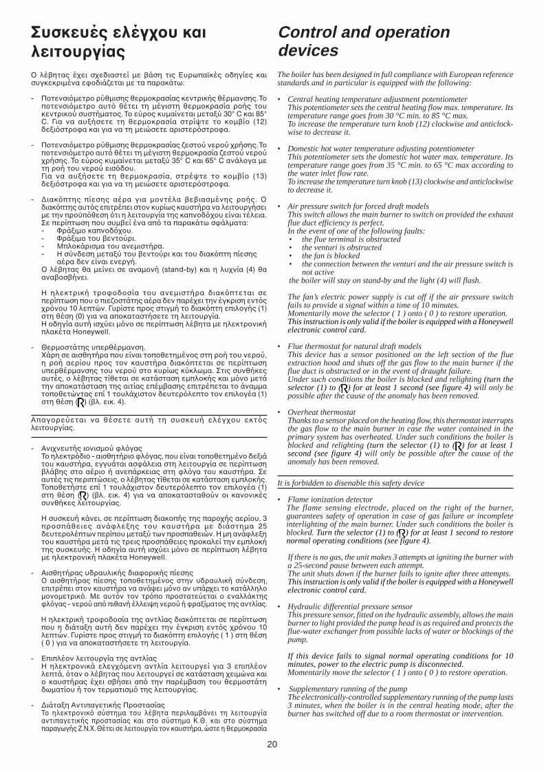
Control and operationdevicesThe boiler has been designed in full compliance with European referencestandards and in particular is equipped with the following:
• Central heating temperature adjustment potentiometerThis potentiometer sets the central heating flow max. temperature. Itstemperature range goes from 30 °C min. to 85 °C max.To increase the temperature turn knob (12) clockwise and anticlock-wise to decrease it.
• Domestic hot water temperature adjusting potentiometerThis potentiometer sets the domestic hot water max. temperature. Itstemperature range goes from 35 °C min. to 65 °C max according tothe water inlet flow rate.To increase the temperature turn knob (13) clockwise and anticlockwiseto decrease it.
• Air pressure switch for forced draft modelsThis switch allows the main burner to switch on provided the exhaustflue duct efficiency is perfect.In the event of one of the following faults:• the flue terminal is obstructed• the venturi is obstructed• the fan is blocked• the connection between the venturi and the air pressure switch is
not activethe boiler will stay on stand-by and the light (4) will flash.
The fan’s electric power supply is cut off if the air pressure switchfails to provide a signal within a time of 10 minutes.Momentarily move the selector ( 1 ) onto ( 0 ) to restore operation.This instruction is only valid if the boiler is equipped with a Honeywellelectronic control card.
• Flue thermostat for natural draft modelsThis device has a sensor positioned on the left section of the flueextraction hood and shuts off the gas flow to the main burner if theflue duct is obstructed or in the event of draught failure.Under such conditions the boiler is blocked and relighting (turn theselector (1) to ( ) for at least 1 second (see figure 4) will only bepossible after the cause of the anomaly has been removed.
• Overheat thermostatThanks to a sensor placed on the heating flow, this thermostat interruptsthe gas flow to the main burner in case the water contained in theprimary system has overheated. Under such conditions the boiler isblocked and relighting (turn the selector (1) to ( ) for at least 1second (see figure 4) will only be possible after the cause of theanomaly has been removed.
It is forbidden to disenable this safety device
• Flame ionization detectorThe flame sensing electrode, placed on the right of the burner,guarantees safety of operation in case of gas failure or incompleteinterlighting of the main burner. Under such conditions the boiler isblocked. Turn the selector (1) to ( ) for at least 1 second to restorenormal operating conditions (see figure 4).
If there is no gas, the unit makes 3 attempts at igniting the burner witha 25-second pause between each attempt.The unit shuts down if the burner fails to ignite after three attempts.This instruction is only valid if the boiler is equipped with a Honeywellelectronic control card.
• Hydraulic differential pressure sensorThis pressure sensor, fitted on the hydraulic assembly, allows the mainburner to light provided the pump head is as required and protects theflue-water exchanger from possible lacks of water or blockings of thepump.
If this device fails to signal normal operating conditions for 10minutes, power to the electric pump is disconnected.Momentarily move the selector ( 1 ) onto ( 0 ) to restore operation.
• Supplementary running of the pumpThe electronically-controlled supplementary running of the pump lasts3 minutes, when the boiler is in the central heating mode, after theburner has switched off due to a room thermostat or intervention.
Συσκευές ελέγυ καιλειτυργίας% λέ!ητας έει σεδιαστεί µε !άση τις Ευρωπαϊκές δηγίες καισυγκεκριµένα εδιάεται µε τα παρακάτω:
- Πτενσιµετρ ρύθµισης θερµκρασίας κεντρικής θέρµανσης. Τπτενσιµετρ αυτ θέτει τη µέγιστη θερµκρασία ρής τυκεντρικύ συστήµατς. Τ εύρς κυµαίνεται µεταύ 30° C και 85°C. Για να αυήσετε τη θερµκρασία στρίψτε τ κµ!ί (12)δειστρα και για να τη µειώσετε αριστερστρα.
- Πτενσιµετρ ρύθµισης θερµκρασίας εστύ νερύ ρήσης. Τπτενσιµετρ αυτ θέτει τη µέγιστη θερµκρασία εστύ νερύρήσης. Τ εύρς κυµαίνεται µεταύ 35° C και 65° C ανάλγα µετη ρή τυ νερύ εισδυ.Για να αυήσετε τη θερµκρασία, στρέψτε τ κµ!ί (13)δειστρα και για να τη µειώσετε αριστερστρα.
- ∆ιακπτης πίεσης αέρα για µντέλα !ε!ιασµένης ρής. %διακπτης αυτς επιτρέπει στν κυρίως καυστήρα να λειτυργήσειµε την πρϋπθεση τι η λειτυργία της καπνδυ είναι τέλεια.Σε περίπτωση πυ συµ!εί ένα απ τα παρακάτω σάλµατα:- Φράιµ καπνδυ.- Φράιµ τυ !εντύρι.- Μπλκάρισµα τυ ανεµιστήρα.- Η σύνδεση µεταύ τυ !εντύρι και τυ διακπτη πίεσης
αέρα δεν είναι ενεργή.% λέ!ητας θα µείνει σε αναµνή (stand-by) και η λυνία (4) θαανα!σ!ήνει.
Η ηλεκτρική τρδσία τυ ανεµιστήρα διακπτεται σεπερίπτωση πυ πιεστάτης αέρα δεν παρέει την έγκριση εντςρνυ 10 λεπτών. Γυρίστε πρς στιγµή τ διακπτη επιλγής (1)στη θέση (0) για να απκαταστήσετε τη λειτυργία.Η δηγία αυτή ισύει µν σε περίπτωση λέ!ητα µε ηλεκτρνικήπλακέτα Honeywell.
- Θερµστάτης υπερθέρµανση._άρη σε αισθητήρα πυ είναι τπθετηµένς στη ρή τυ νερύ,η ρή αερίυ πρς τν καυστήρα διακπτεται σε περίπτωσηυπερθέρµανσης τυ νερύ στ κυρίως κύκλωµα. Στις συνθήκεςαυτές, λέ!ητας τίθεται σε κατάσταση εµπλκής και µν µετάτην απκατάσταση της αιτίας επέµ!ασης επιτρέπεται τ άναµµατπθετώντας επί 1 τυλάιστν δευτερλεπτ τν επιλγέα (1)στη θέση ( ) (!λ. εικ. 4).
Απαγρεύεται να θέσετε αυτή τη συσκευή ελέγυ εκτςλειτυργίας.
- Ανινευτής ινισµύ λγαςΤ ηλεκτρδι - αισθητήρι λγας, πυ είναι τπθετηµέν δειάτυ καυστήρα, εγγυάται ασάλεια στη λειτυργία σε περίπτωση!λά!ης στ αέρι ή ανεπάρκειας στη λγα τυ καυστήρα. Σεαυτές τις περιπτώσεις, λέ!ητας τίθεται σε κατάσταση εµπλκής.Τπθετήστε επί 1 τυλάιστν δευτερλεπτ τν επιλγέα (1)στη θέση ( ) (!λ. εικ. 4) για να απκατασταθύν ι καννικέςσυνθήκες λειτυργίας.
Η συσκευή κάνει, σε περίπτωση διακπής της παρής αερίυ, 3πρσπάθειες ανάλεης τυ καυστήρα µε διάστηµα 25δευτερλέπτων περίπυ µεταύ των πρσπαθειών. Η µη ανάλεητυ καυστήρα µετά τις τρεις πρσπάθειες πρκαλεί την εµπλκήτης συσκευής. Η δηγία αυτή ισύει µν σε περίπτωση λέ!ηταµε ηλεκτρνική πλακέτα Honeywell.
- Αισθητήρας υδραυλικής διαρικής πίεσης% αισθητήρας πίεσης τπθετηµένς στην υδραυλική σύνδεση,επιτρέπει στν καυστήρα να ανάψει µν αν υπάρει τ κατάλληλµνµετρικ. Με αυτν τν τρπ πρστατεύεται εναλλάκτηςλγας - νερύ απ πιθανή έλλειψη νερύ ή ραίµατς της αντλίας.
Η ηλεκτρική τρδσία της αντλίας διακπτεται σε περίπτωσηπυ η διάταη αυτή δεν παρέει την έγκριση εντς ρνυ 10λεπτών. Γυρίστε πρς στιγµή τ διακπτη επιλγής ( 1 ) στη θέση( 0 ) για να απκαταστήσετε τη λειτυργία.
- Επιπλέν λειτυργία της αντλίαςΗ ηλεκτρνικά ελεγµενη αντλία λειτυργεί για 3 επιπλένλεπτά, ταν λέ!ητας πυ λειτυργεί σε κατάσταση ειµώνα και καυστήρας έει σ!ήσει απ την παρέµ!αση τυ θερµστάτηδωµατίυ ή τν τερµατισµ της λειτυργίας.
- ∆ιάταη Αντιπαγετικής ΠρστασίαςΤ ηλεκτρνικ σύστηµα τυ λέ!ητα περιλαµ!άνει τη λειτυργίααντιπαγετικής πρστασίας και στ σύστηµα Κ.Θ. και στ σύστηµαπαραγωγής j.Ν._. Θέτει σε λειτυργία τν καυστήρα, ώστε η θερµκρασία
21
0002
1006
00
SCHEDA A - BOARD A
0002
1007
00
SCHEDA B - BOARD B
SCHEDA A - BOARD A SCHEDA B - BOARD B
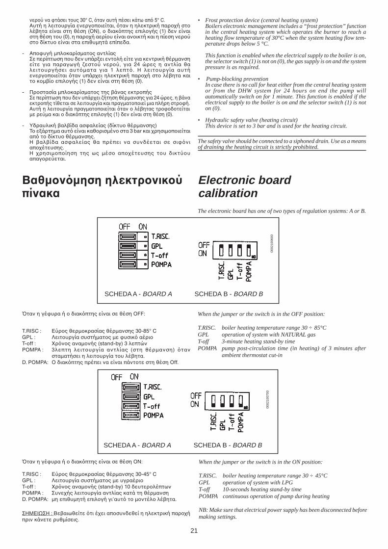
Bταν η γέυρα ή διακπτης είναι σε θέση %Ν:
T.RISC : Εύρς θερµκρασίας θέρµανσης 30-45° CGPL : Λειτυργία συστήµατς µε υγραέριΤ-off : _ρνς αναµνής (stand-by) 10 δευτερλέπτωνPOMPA : Συνεής λειτυργία αντλίας κατά τη θέρµανσηD. POMPA: µη επιθυµητή επιλγή γι’αυτ τ µντέλ λέ!ητα.
ΣΗΜΕΙΩΣΗ : Βε!αιωθείτε τι έει απσυνδεθεί η ηλεκτρική παρήπριν κάνετε ρυθµίσεις.
When the jumper or the switch is in the ON position:
T.RISC. boiler heating temperature range 30 ÷ 45°CGPL operation of system with LPGT-off 10-seconds heating stand-by timePOMPA continuous operation of pump during heating
NB: Make sure that electrical power supply has been disconnected beforemaking settings.
Bταν η γέυρα ή διακπτης είναι σε θέση OFF:
T.RISC : Εύρς θερµκρασίας θέρµανσης 30-85° CGPL : Λειτυργία συστήµατς µε υσικ αέριΤ-off : _ρνς αναµνής (stand-by) 3 λεπτώνPOMPA : 3λεπτη λειτυργία αντλίας (στη θέρµανση) ταν
σταµατήσει η λειτυργία τυ λέ!ητα.D. POMPA: % διακπτης πρέπει να είναι πάνττε στη θέση Off.
When the jumper or the switch is in the OFF position:
T.RISC. boiler heating temperature range 30 ÷ 85°CGPL operation of system with NATURAL gasT-off 3-minute heating stand-by timePOMPA pump post-circulation time (in heating) of 3 minutes after
ambient thermostat cut-in
Electronic boardcalibrationThe electronic board has one of two types of regulation systems: A or B.
Βαθµνµηση ηλεκτρνικύπίνακα
• Frost protection device (central heating system)Boilers electronic management includes a “frost protection” functionin the central heating system which operates the burner to reach aheating flow temperature of 30°C when the system heating flow tem-perature drops below 5 °C.
This function is enabled when the electrical supply to the boiler is on,the selector switch (1) is not on (0), the gas supply is on and the systempressure is as required.
• Pump-blocking preventionIn case there is no call for heat either from the central heating systemor from the DHW system for 24 hours on end the pump willautomatically switch on for 1 minute. This function is enabled if theelectrical supply to the boiler is on and the selector switch (1) is noton (0).
• Hydraulic safety valve (heating circuit)This device is set to 3 bar and is used for the heating circuit.
The safety valve should be connected to a siphoned drain. Use as a meansof draining the heating circuit is strictly prohibited.
νερύ να τάσει τυς 30° C, ταν αυτή πέσει κάτω απ 5° C.Αυτή η λειτυργία ενεργπιείται, ταν η ηλεκτρική παρή στλέ!ητα είναι στη θέση (%Ν), διακπτης επιλγής (1) δεν είναιστη θέση τυ (0), η παρή αερίυ είναι ανικτή και η πίεση νερύστ δίκτυ είναι στα επιθυµητά επίπεδα.
- Απυγή µπλκαρίσµατς αντλίαςΣε περίπτωση πυ δεν υπάρει εντλή είτε για κεντρική θέρµανσηείτε για παραγωγή εστύ νερύ, για 24 ώρες η αντλία θαλειτυργήσει αυτµατα για 1 λεπτ. Η λειτυργία αυτήενεργπιείται ταν υπάρει ηλεκτρική παρή στ λέ!ητα καιτ κµ!ί επιλγής (1) δεν είναι στη θέση (0).
- Πρστασία µπλκαρίσµατς της !άνας εκτρπήςΣε περίπτωση πυ δεν υπάρει ήτηση θέρµανσης για 24 ώρες, η !άναεκτρπής τίθεται σε λειτυργία και πραγµατπιεί µια πλήρη στρή.Αυτή η λειτυργία πραγµατπιείται ταν λέ!ητας τρδτείταιµε ρεύµα και διακπτης επιλγής (1) δεν είναι στη θέση (0).
- Υδραυλική !αλ!ίδα ασαλείας (δίκτυ θέρµανσης)Τ εάρτηµα αυτ είναι καθρισµέν στα 3 bar και ρησιµπιείταιαπ τ δίκτυ θέρµανσης.Η !αλ!ίδα ασαλείας θα πρέπει να συνδέεται σε σινιαπέτευσης.Η ρησιµπίηση της ως µέσ απέτευσης τυ δικτύυαπαγρεύεται.
22
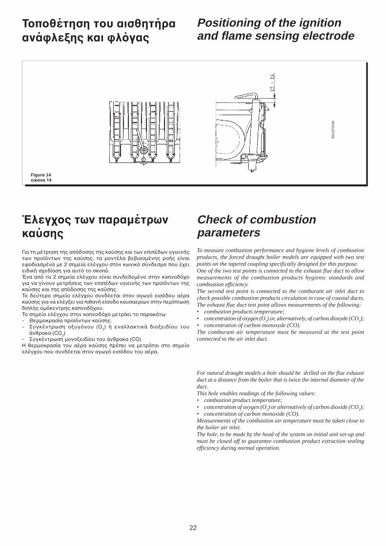
Positioning of the ignitionand flame sensing electrode
Figura 14εικνα 14
9912
0701
00
Check of combustionparametersTo measure combustion performance and hygiene levels of combustionproducts, the forced draught boiler models are equipped with two testpoints on the tapered coupling specifically designed for this purpose.One of the two test points is connected to the exhaust flue duct to allowmeasurements of the combustion products hygienic standards andcombustion efficiency.The second test point is connected to the comburant air inlet duct tocheck possible combustion products circulation in case of coaxial ducts.The exhaust flue duct test point allows measurements of the following:• combustion products temperature;• concentration of oxygen (O
2) or, alternatively, of carbon dioxyde (CO
2);
• concentration of carbon monoxyde (CO).The comburant air temperature must be measured at the test pointconnected to the air inlet duct.
For natural draught models a hole should be drilled on the flue exhaustduct at a distance from the boiler that is twice the internal diameter of theduct.This hole enables readings of the following values:• combustion product temperature;• concentration of oxygen (O
2) or alternatively of carbon dioxide (CO
2);
• concentration of carbon monoxide (CO).Measurements of the combustion air temperature must be taken close tothe boiler air inlet.The hole, to be made by the head of the system on initial unit set-up andmust be closed off to guarantee combustion product extraction sealingefficiency during normal operation.
Τπθέτηση τυ αισθητήραανά%λεCης και %λγας
Έλεγς των παραµέτρωνκαύσηςΓια τη µέτρηση της απδσης της καύσης και των επιπέδων υγιεινήςτων πρϊντων της καύσης, τα µντέλα !ε!ιασµένης ρής είναιεδιασµένα µε 2 σηµεία ελέγυ στν κωνικ σύνδεσµ πυ έειειδική σεδίαση για αυτ τ σκπ.Ένα απ τα 2 σηµεία ελέγυ είναι συνδεδεµέν στην καπνδγια να γίνυν µετρήσεις των επιπέδων υγιεινής των πρϊντων τηςκαύσης και της απδσης της καύσης.Τ δεύτερ σηµεί ελέγυ συνδέεται στν αγωγ εισδυ αέρακαύσης για να ελέγει για πιθανή είσδ καυσαερίων στην περίπτωσηδιπλής µκεντρης καπνδυ.Τ σηµεί ελέγυ στην καπνδ µετράει τ παρακάτω:- Θερµκρασία πρϊντων καύσης.- Συγκέντρωση υγνυ (%2) ή εναλλακτικά διειδίυ τυ
άνθρακα (CO2).- Συγκέντρωση µνειδίυ τυ άνθρακα (CO).Η θερµκρασία τυ αέρα καύσης πρέπει να µετράται στ σηµείελέγυ πυ συνδέεται στν αγωγ εισδυ τυ αέρα.
23
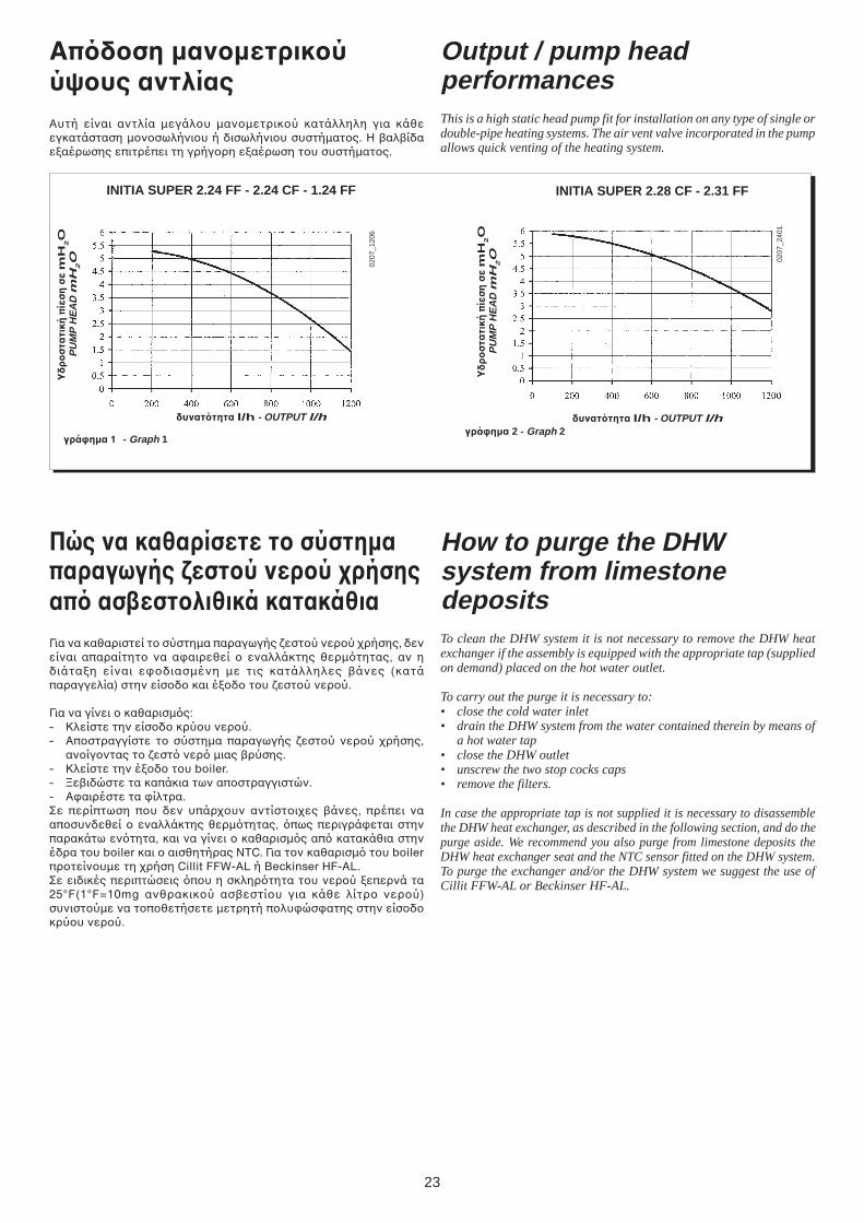
Output / pump headperformancesThis is a high static head pump fit for installation on any type of single ordouble-pipe heating systems. The air vent valve incorporated in the pumpallows quick venting of the heating system.
Απδση µανµετρικύύψυς αντλίαςΑυτή είναι αντλία µεγάλυ µανµετρικύ κατάλληλη για κάθεεγκατάσταση µνσωλήνιυ ή δισωλήνιυ συστήµατς. Η !αλ!ίδαεαέρωσης επιτρέπει τη γρήγρη εαέρωση τυ συστήµατς.
How to purge the DHWsystem from limestonedepositsTo clean the DHW system it is not necessary to remove the DHW heatexchanger if the assembly is equipped with the appropriate tap (suppliedon demand) placed on the hot water outlet.
To carry out the purge it is necessary to:• close the cold water inlet• drain the DHW system from the water contained therein by means of
a hot water tap• close the DHW outlet• unscrew the two stop cocks caps• remove the filters.
In case the appropriate tap is not supplied it is necessary to disassemblethe DHW heat exchanger, as described in the following section, and do thepurge aside. We recommend you also purge from limestone deposits theDHW heat exchanger seat and the NTC sensor fitted on the DHW system.To purge the exchanger and/or the DHW system we suggest the use ofCillit FFW-AL or Beckinser HF-AL.
Πώς να καθαρίσετε τ σύστηµαπαραγωγής =εστύ νερύ ρήσηςαπ ασεστλιθικά κατακάθιαΓια να καθαριστεί τ σύστηµα παραγωγής εστύ νερύ ρήσης, δενείναι απαραίτητ να ααιρεθεί εναλλάκτης θερµτητας, αν ηδιάταη είναι εδιασµένη µε τις κατάλληλες !άνες (κατάπαραγγελία) στην είσδ και έδ τυ εστύ νερύ.
Για να γίνει καθαρισµς:- Κλείστε την είσδ κρύυ νερύ.- Απστραγγίστε τ σύστηµα παραγωγής εστύ νερύ ρήσης,
ανίγντας τ εστ νερ µιας !ρύσης.- Κλείστε την έδ τυ boiler.- dε!ιδώστε τα καπάκια των απστραγγιστών.- Ααιρέστε τα ίλτρα.Σε περίπτωση πυ δεν υπάρυν αντίστιες !άνες, πρέπει νααπσυνδεθεί εναλλάκτης θερµτητας, πως περιγράεται στηνπαρακάτω εντητα, και να γίνει καθαρισµς απ κατακάθια στηνέδρα τυ boiler και αισθητήρας ΝΤC. Για τν καθαρισµ τυ boilerπρτείνυµε τη ρήση Cillit FFW-AL ή Beckinser HF-AL.Σε ειδικές περιπτώσεις πυ η σκληρτητα τυ νερύ επερνά τα25°F(1°F=10mg ανθρακικύ ασ!εστίυ για κάθε λίτρ νερύ)συνιστύµε να τπθετήσετε µετρητή πλυώσατης στην είσδκρύυ νερύ.
δυναττητα l/h - OUTPUT l/h
γρά%ηµα 1 - Graph 1
Υδ
ρ
στα
τική
πίε
ση
σε m
H2O
PU
MP
HE
AD
mH
2O
INITIA SUPER 2.24 FF - 2.24 CF - 1.24 FF INITIA SUPER 2.28 CF - 2.31 FF
δυναττητα l/h - OUTPUT l/h
Υδ
ρ
στα
τική
πίε
ση
σε m
H2O
PU
MP
HE
AD
mH
2O
γρά%ηµα 2 - Graph 2
0207
_120
6
0207
_240
1
24
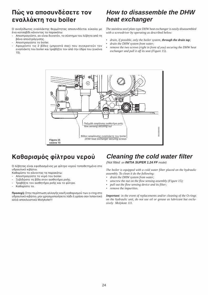
Figura 15εικνα 15
Βίδες ασάλισης εναλλάκτη τυ boilerDHW heat exchanger securing screws
Παιµάδι ασάλισης αισθητήρα ρήςflow sensing securing nut
9910
0804
00
Πώς να απσυνδέσετε τνεναλλάκτη τυ boiler% ανείδωτς εναλλάκτης θερµτητας απσυνδέεται εύκλα µεένα κατσα!ίδι κάνντας τα παρακάτω:- Απστραγγίστε, αν είναι δυνατν, τ σύστηµα τυ λέ!ητα απ τη
!άνα απστράγγισης.- Απστραγγίστε τ boiler.- Ααιρέστε τις 2 !ίδες (µπρστά σας) πυ συγκρατύν τν
εναλλάκτη τυ boiler και τρα!ήτε τν απ την έδρα τυ (εικνα15).
How to disassemble the DHWheat exchangerThe stainless steel plate-type DHW heat exchanger is easily disassembledwith a screwdriver by operating as described below:
• drain, if possible, only the boiler system, through the drain tap;• drain the DHW system from water;• remove the two screws (right in front of you) securing the DHW heat
exchanger and pull it off its seat (Figure 15).
Cleaning the cold water filter(Not fitted on INITIA SUPER 1.24 FF model)
The boiler is equipped with a cold water filter placed on the hydraulicassembly. To clean it do the following:• drain the DHW system from water;• unscrew the nut on the flow sensing assembly (Figure 15);• pull out the flow sensing device and its filter;• remove the impurities.
Important: in the event of replacements and/or cleaning of the O-ringson the hydraulic unit, do not use oil or grease as lubricant but exclu-sively Molykote 111.
Καθαρισµς %ίλτρυ νερύ% λέ!ητας είναι εδιασµένς µε ίλτρ νερύ τπθετηµέν στυδραυλικ κι!ώτι.Καθαρίστε τ κάνντας τα παρακάτω:- Απστραγγίστε τ νερ τυ boiler.- dε!ιδώστε τη !ίδα στν αισθητήρα ρής.- Τρα!ήτε τν αισθητήρα ρής και τ ίλτρ.- Καθαρίστε τ.
Πρσή: Στην περίπτωση αλλαγής και/ή καθαρισµύ των o-ring στυδραυλικ κι!ώτι, µην ρησιµπιήσετε λάδι ή γράσ σαν λιπαντικαλλά απκλειστικά Molykote!!!
25
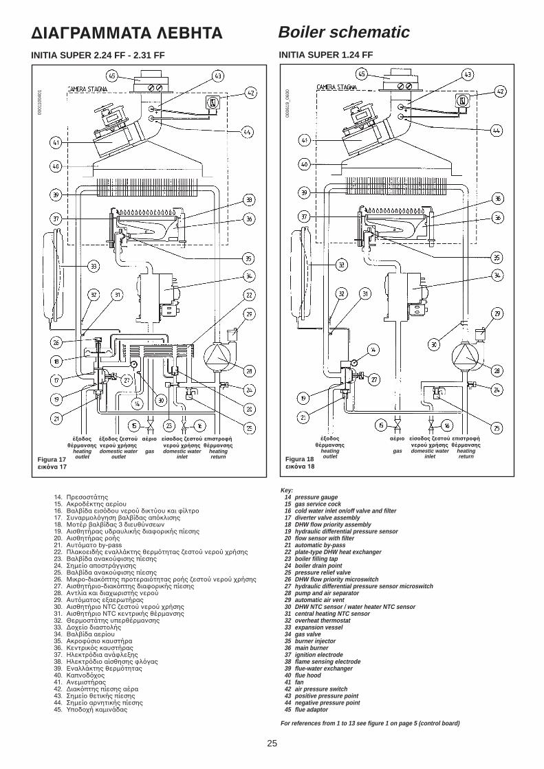
Boiler schematic∆ΙΑΓΡΑΜΜΑΤΑ ΛΕΒΗΤΑ
έCδς έCδς =εστύ αέρι είσδς =εστύ επιστρ%ήθέρµανσης νερύ ρήσης νερύ ρήσης θέρµανσης
heating domestic water gas domestic water heatingoutlet outlet inlet return
14. Πρεσστάτης15. Ακρδέκτης αερίυ16. Βαλ!ίδα εισδυ νερύ δικτύυ και ίλτρ17. Συναρµλγηση !αλ!ίδας απκλισης18. Μτέρ !αλ!ίδας 3 διευθύνσεων19. Αισθητήρας υδραυλικής διαρικής πίεσης20. Αισθητήρας ρής21. Αυτµατ by-pass22. Πλακειδής εναλλάκτης θερµτητας εστύ νερύ ρήσης23. Βαλ!ίδα ανακύισης πίεσης24. Σηµεί απστράγγισης25. Βαλ!ίδα ανακύισης πίεσης26. Μικρ-διακπτης πρτεραιτητας ρής εστύ νερύ ρήσης27. Αισθητήρι-διακπτης διαρικής πίεσης28. Αντλία και διαωριστής νερύ29. Αυτµατς εαερωτήρας30. Αισθητήρι NTC εστύ νερύ ρήσης31. Αισθητήρι NTC κεντρικής θέρµανσης32. Θερµστάτης υπερθέρµανσης33. ∆εί διαστλής34. Βαλ!ίδα αερίυ35. Ακρύσι καυστήρα36. Κεντρικς καυστήρας37. Ηλεκτρδια ανάλεης38. Ηλεκτρδι αίσθησης λγας39. Εναλλάκτης θερµτητας40. Καπνδς41. Ανεµιστήρας42. ∆ιακπτης πίεσης αέρα43. Σηµεί θετικής πίεσης44. Σηµεί αρνητικής πίεσης45. Υπδή καµινάδας
Key:14 pressure gauge15 gas service cock16 cold water inlet on/off valve and filter17 diverter valve assembly18 DHW flow priority assembly19 hydraulic differential pressure sensor20 flow sensor with filter21 automatic by-pass22 plate-type DHW heat exchanger23 boiler filling tap24 boiler drain point25 pressure relief valve26 DHW flow priority microswitch27 hydraulic differential pressure sensor microswitch28 pump and air separator29 automatic air vent30 DHW NTC sensor / water heater NTC sensor31 central heating NTC sensor32 overheat thermostat33 expansion vessel34 gas valve35 burner injector36 main burner37 ignition electrode38 flame sensing electrode39 flue-water exchanger40 flue hood41 fan42 air pressure switch43 positive pressure point44 negative pressure point45 flue adaptor
For references from 1 to 13 see figure 1 on page 5 (control board)
Figura 17εικνα 17
0001
1004
01
INITIA SUPER 2.24 FF - 2.31 FF
έCδς αέρι είσδς =εστύ επιστρ%ήθέρµανσης νερύ ρήσης θέρµανσης
heating gas domestic water heatingoutlet inlet returnFigura 18
εικνα 18
0006
19_0
600
INITIA SUPER 1.24 FF
26
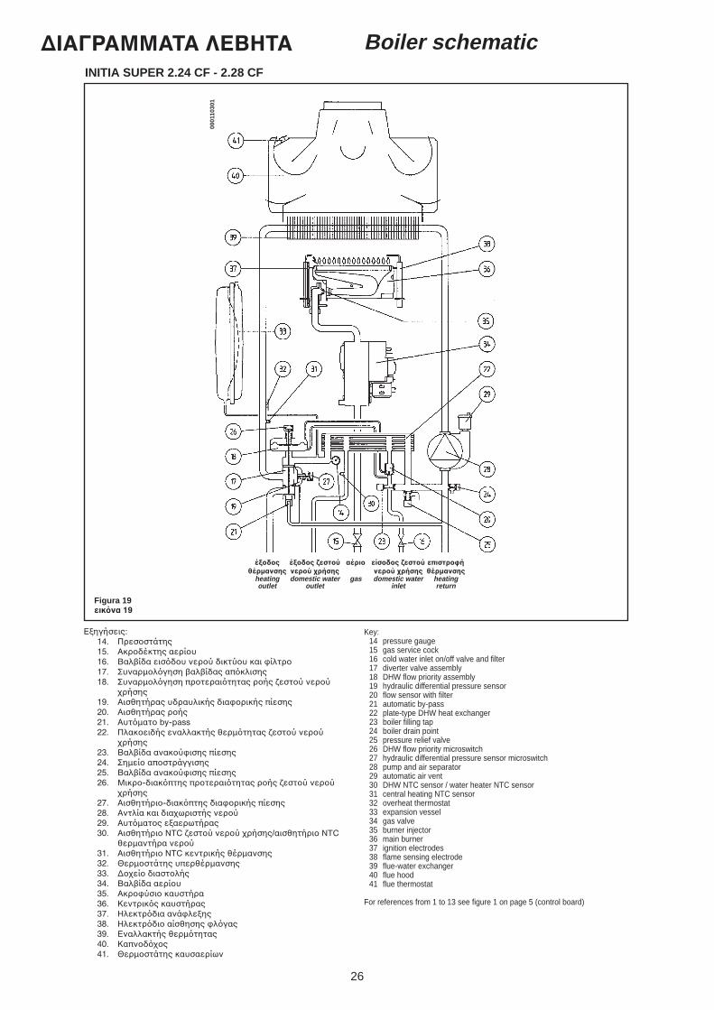
Boiler schematic∆ΙΑΓΡΑΜΜΑΤΑ ΛΕΒΗΤΑINITIA SUPER 2.24 CF - 2.28 CF
Εηγήσεις:14. Πρεσστάτης15. Ακρδέκτης αερίυ16. Βαλ!ίδα εισδυ νερύ δικτύυ και ίλτρ17. Συναρµλγηση !αλ!ίδας απκλισης18. Συναρµλγηση πρτεραιτητας ρής εστύ νερύ
ρήσης19. Αισθητήρας υδραυλικής διαρικής πίεσης20. Αισθητήρας ρής21. Αυτµατ by-pass22. Πλακειδής εναλλακτής θερµτητας εστύ νερύ
ρήσης23. Βαλ!ίδα ανακύισης πίεσης24. Σηµεί απστράγγισης25. Βαλ!ίδα ανακύισης πίεσης26. Μικρ-διακπτης πρτεραιτητας ρής εστύ νερύ
ρήσης27. Αισθητήρι-διακπτης διαρικής πίεσης28. Αντλία και διαωριστής νερύ29. Αυτµατς εαερωτήρας30. Αισθητήρι NTC εστύ νερύ ρήσης/αισθητήρι NTC
θερµαντήρα νερύ31. Αισθητήρι NTC κεντρικής θέρµανσης32. Θερµστάτης υπερθέρµανσης33. ∆εί διαστλής34. Βαλ!ίδα αερίυ35. Ακρύσι καυστήρα36. Κεντρικς καυστήρας37. Ηλεκτρδια ανάλεης38. Ηλεκτρδι αίσθησης λγας39. Εναλλακτής θερµτητας40. Καπνδς41. Θερµστάτης καυσαερίων
έCδς έCδς =εστύ αέρι είσδς =εστύ επιστρ%ήθέρµανσης νερύ ρήσης νερύ ρήσης θέρµανσης
heating domestic water gas domestic water heatingoutlet outlet inlet return
Figura 19εικνα 19
0001
1030
1
Key:14 pressure gauge15 gas service cock16 cold water inlet on/off valve and filter17 diverter valve assembly18 DHW flow priority assembly19 hydraulic differential pressure sensor20 flow sensor with filter21 automatic by-pass22 plate-type DHW heat exchanger23 boiler filling tap24 boiler drain point25 pressure relief valve26 DHW flow priority microswitch27 hydraulic differential pressure sensor microswitch28 pump and air separator29 automatic air vent30 DHW NTC sensor / water heater NTC sensor31 central heating NTC sensor32 overheat thermostat33 expansion vessel34 gas valve35 burner injector36 main burner37 ignition electrodes38 flame sensing electrode39 flue-water exchanger40 flue hood41 flue thermostat
For references from 1 to 13 see figure 1 on page 5 (control board)
27
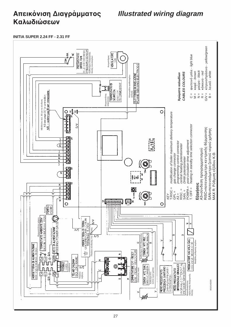
Illustrated wiring diagramΑπεικνιση ∆ιαγράµµατςΚαλωδιώσεων
0010
1402
00
!ρ
ώµ
ατα
κα
λωδ
ίων
CA
BL
ES
CO
LO
UR
S
C =
ω
τειν
µ
πλε
- li
ght b
lue
M =
κα
έ -
brow
nN
=µ
αύ
ρ
- b
lack
R =
κκκ
ιν
- r
edG
/V =
κίτρ
ιν
/πρ
άσ
ιν
- y
ello
w/g
reen
B =
λευ
κ -
whi
te
KE
YT.
RIS
C =
mod
ifica
tion
of b
oile
r m
axim
um d
eliv
ery
tem
pera
ture
GP
L =
gas
chan
ge c
onne
ctor
A3
=pr
ogra
mm
ing
cont
rol c
onne
ctor
RIS
C. =
cent
ral h
eatin
g po
tent
iom
eter
SA
N. =
DH
W p
oten
tiom
eter
PO
MP
A =
post
-circ
ulat
ion
time
adju
stm
ent
T. O
FF
=he
atin
g in
sta
ndby
tim
e se
lect
ion
conn
ecto
r
ΕCη
γήσ
εις
Α3=
σύ
νδεσ
η π
ρ
γρα
µµ
ατι
σµ
ύ
RIS
C=
π
τενσ
ιµ
ετρ
κ
εντρ
ική
ς θ
έρµ
ανσ
ης
SA
N=
π
τενσ
ιµ
ετρ
εστ
ύ ν
ερ
ύ
ρή
ση
ςM
AX
R: Ρ
ύθ
µισ
η ε
δ
υ
Κ.Θ
.
Ηλε
κτρ
δ
ι α
ισθ
ητη
ρί
υ
λγα
ς
Ανε
µισ
τήρ
ας
Θερ
µ
στά
της
ασ
α
λεία
ς
Αισ
θη
τήρ
ι δ
ια
ρ
ική
ςπ
ίεσ
ης
καυ
σα
ερίω
ν
Πλα
ίσι
Θερ
µ
στά
της
ώρ
υ
∆ίκ
τυ
ρεύ
µα
τς
Ασ
ά
λεια
Πλα
ίσι
λέ!
ητα
Πλα
ίσι
σύ
νδεσ
ης
της
γείω
ση
ς
Βα
λ!ίδ
α ρ
ύθ
µισ
ης
αερ
ίυ
Επ
ιλ
γέα
ς re
set
Μικ
ρ
δια
κπ
της
υδ
ρα
υλι
κής
δια
ρικ
ής
πίε
ση
ς
Αισ
θη
τήρ
ι N
TC
θέρ
µα
νση
ς
Αισθ
ητήρ
ι N
TCε
στύ
νερ
ύ
ρήση
ς
Αντ
λία
ΝΒ
:Βλέ
πε
σελ
. 30
για
τη
σύ
νδεσ
η
INITIA SUPER 2.24 FF - 2.31 FF
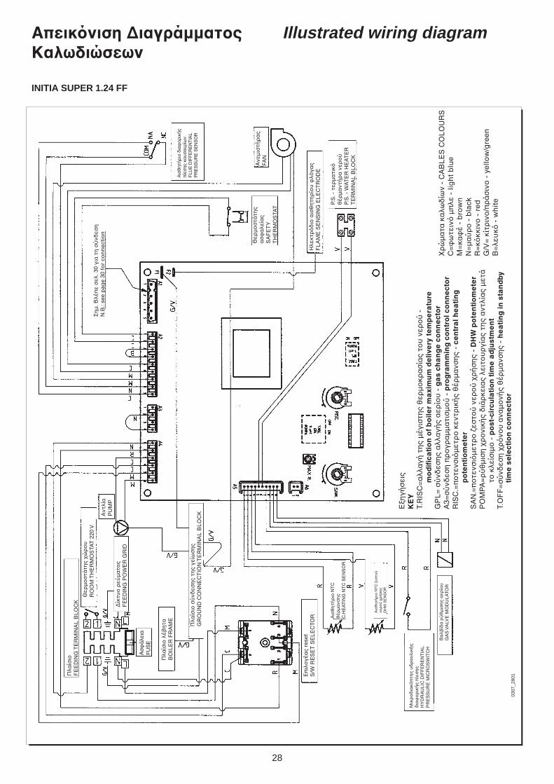
28
Illustrated wiring diagramΑπεικνιση ∆ιαγράµµατςΚαλωδιώσεων
INITIA SUPER 1.24 FF
0307
_280
1Πλα
ίσι
FE
ED
ING
TE
RM
INA
L B
LO
CK
Θερ
µ
στά
της
ώρ
υ
RO
OM
TH
ER
MO
STA
T 2
20 V
∆ίκ
τυ
ρεύ
µα
τς
FE
ED
ING
PO
WE
R G
RID
Πλα
ίσι
λέ!
ητα
BO
ILE
R F
RA
ME
Ασ
άλει
αFU
SE
Πλα
ίσι
σύ
νδεσ
ης
της
γείω
ση
ςG
RO
UN
D C
ON
NE
CT
ION
TE
RM
INA
L B
LO
CK
Επ
ιλ
γέα
ς re
set
S/W
RE
SE
T S
EL
EC
T OR
Αισ
θη
τήρ
ι Ν
ΤC
εσ
τύ
νερ
ύ
ρ
ήσ
ης
DH
W S
EN
SO
R
Αισ
θη
τήρ
ι Ν
ΤC
θέρ
µα
νση
ςC
.HE
AT
ING
NT
C S
EN
SO
R
Μικ
ρ
δια
κπ
της
υδ
ρα
υλι
κής
δια
ρικ
ής
πίε
ση
ςH
YD
RA
UL
IC D
IFF
ER
EN
TIA
LP
RE
SS
UR
E M
ICR
OS
WIT
CH
Βα
λ!ίδ
α ρ
ύθ
µισ
ης
αερ
ίυ
GA
S V
ALV
E M
OD
UL
ATO
R
Ση
µ. Β
λέπ
ε σ
ελ. 3
0 γι
α τ
η σ
ύνδ
εση
N.B
.: se
e p
age
30 f
or
con
nec
tio
nΑ
ντλί
αP
UM
P
Θερ
µ
στά
της
ασ
α
λεία
ςS
AF
ET
YT
HE
RM
OS
TAT
Ηλε
κτρ
δ
ι α
ισθ
ητη
ρί
υ
λγα
ςF
LA
ME
SE
NS
ING
EL
EC
TR
OD
E
Αισ
θη
τήρ
ι δ
ια
ρ
ική
ςπ
ίεσ
ης
καυ
σα
ερίω
νF
LU
E D
IFF
ER
EN
TIA
LP
RE
SS
UR
E S
EN
SO
R
Ανε
µισ
τήρ
ας
FAN
_ρ
ώµ
ατα
κα
λωδ
ίων
- C
AB
LE
S C
OL
OU
RS
C=
ω
τειν
µ
πλε
- li
gh
t b
lue
Μ=
κα
έ -
bro
wn
Ν=
µα
ύρ
-
bla
ckR
=κ
κκιν
-
red
G/V
= κ
ίτρ
ιν
/πρ
άσ
ιν
- y
ello
w/g
reen
Β=
λευ
κ -
wh
ite
Εη
γήσ
εις
KE
YΤ.
RIS
C=
αλλ
αγή
τη
ς µ
έγισ
της
θερ
µ
κρα
σία
ς τ
υ ν
ερ
ύ -
mo
dif
ica
tio
n o
f b
oile
r m
axi
mu
m d
eliv
ery
te
mp
era
ture
GP
L=
σύ
νδεσ
ης
αλλ
αγή
ς α
ερί
υ -
ga
s ch
an
ge
co
nn
ect
or
Α3=
σύ
νδεσ
η π
ρ
γρα
µµ
ατι
σµ
ύ
- p
rog
ram
min
g c
on
tro
l co
nn
ect
or
RIS
C.=
π
τενσ
ιµ
ετρ
κ
εντρ
ική
ς θ
έρµ
ανσ
ης
- ce
ntr
al h
ea
tin
gp
ote
nti
om
ete
rS
ΑΝ
.=π
τε
νσι
µετ
ρ
εσ
τύ
νερ
ύ
ρ
ήσ
ης
- D
HW
po
ten
tio
me
ter
Ρ%
ΜΡ
Α=
ρύ
θµ
ιση
ρ
νι
κής
διά
ρκε
ιας
λειτ
υ
ργί
ας
της
αντ
λία
ς µ
ετά
τ κ
λείσ
ιµ
- p
ost
-cir
cula
tio
n t
ime
ad
just
me
nt
Τ.%
FF
=σ
ύνδ
εση
ρ
ν
υ α
ναµ
νή
ς θ
έρµ
ανσ
ης
- h
ea
tin
g in
sta
nd
b yti
me
se
lect
ion
co
nn
ect
or
P.S
. - τ
ερµ
ατι
κθ
έρµ
αντ
ήρ
α ν
ερ
ύP.
S. -
WA
TE
R H
EA
TE
RT
ER
MIN
AL
BL
OC
K
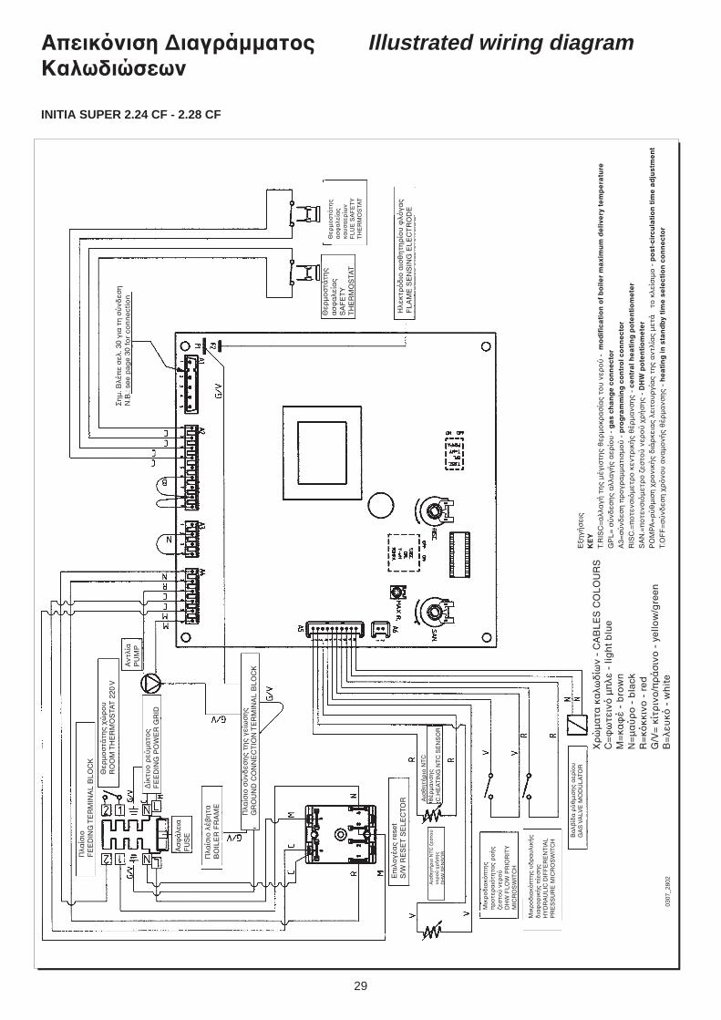
29
Illustrated wiring diagramΑπεικνιση ∆ιαγράµµατςΚαλωδιώσεων
INITIA SUPER 2.24 CF - 2.28 CF
0307
_280
2
Πλα
ίσι
FE
ED
ING
TE
RM
INA
L B
LO
CK
Θερ
µ
στά
της
ώρ
υ
RO
OM
TH
ER
MO
STA
T 2
20 V
∆ίκ
τυ
ρεύ
µα
τς
FE
ED
ING
PO
WE
R G
RID
Πλα
ίσι
λέ!
ητα
BO
ILE
R F
RA
ME
Ασ
άλει
αFU
SE
Πλα
ίσι
σύ
νδεσ
ης
της
γείω
ση
ςG
RO
UN
D C
ON
NE
CT
ION
TE
RM
INA
L B
LO
CK
Επ
ιλ
γέα
ς re
set
S/W
RE
SE
T S
EL
EC
T OR
Αισ
θη
τήρ
ι Ν
ΤC
εσ
τύ
νερ
ύ
ρ
ήσ
ης
DH
W S
EN
SO
R
Αισ
θη
τήρ
ι Ν
ΤC
θέρ
µα
νση
ςC
.HE
AT
ING
NT
C S
EN
SO
R
Μικ
ρ
δια
κπ
της
υδ
ρα
υλι
κής
δια
ρικ
ής
πίε
ση
ςH
YD
RA
UL
IC D
IFF
ER
EN
TIA
LP
RE
SS
UR
E M
ICR
OS
WIT
CH
Βα
λ!ίδ
α ρ
ύθ
µισ
ης
αερ
ίυ
GA
S V
ALV
E M
OD
UL
ATO
R
Ση
µ. Β
λέπ
ε σ
ελ. 3
0 γι
α τ
η σ
ύνδ
εση
N.B
.: se
e p
age
30 f
or
con
nec
tio
nΑ
ντλί
αP
UM
P
Θερ
µ
στά
της
ασ
α
λεία
ςS
AF
ET
YT
HE
RM
OS
TAT
Ηλε
κτρ
δ
ι α
ισθ
ητη
ρί
υ
λγα
ςF
LA
ME
SE
NS
ING
EL
EC
TR
OD
E
_ρ
ώµ
ατα
κα
λωδ
ίων
- C
AB
LE
S C
OL
OU
RS
C=
ω
τειν
µ
πλε
- li
gh
t b
lue
Μ=
κα
έ -
bro
wn
Ν=
µα
ύρ
-
bla
c kR
=κ
κκιν
-
red
G/V
= κ
ίτρ
ιν
/πρ
άσ
ιν
- y
ello
w/g
reen
Β=
λευ
κ -
wh
ite
Εη
γήσ
εις
KE
YΤ.
RIS
C=
αλλ
αγή
τη
ς µ
έγισ
της
θερ
µ
κρα
σία
ς τ
υ ν
ερ
ύ -
mo
dif
ica
tio
n o
f b
oile
r m
axi
mu
m d
eliv
ery
te
mp
era
ture
GP
L=
σύ
νδεσ
ης
αλλ
αγή
ς α
ερί
υ -
ga
s ch
an
ge
co
nn
ect
or
Α3=
σύ
νδεσ
η π
ρ
γρα
µµ
ατι
σµ
ύ
- p
rog
ram
min
g c
on
tro
l co
nn
ect
or
RIS
C.=
π
τενσ
ιµ
ετρ
κ
εντρ
ική
ς θ
έρµ
ανσ
ης
- ce
ntr
al h
ea
tin
g p
ote
nti
om
ete
rS
ΑΝ
.=π
τε
νσι
µετ
ρ
εσ
τύ
νερ
ύ
ρ
ήσ
ης
- D
HW
po
ten
tio
me
ter
Ρ%
ΜΡ
Α=
ρύ
θµ
ιση
ρ
νι
κής
διά
ρκε
ιας
λειτ
υ
ργί
ας
της
αντ
λία
ς µ
ετά
τ κ
λείσ
ιµ
- p
ost
-cir
cula
tio
n t
ime
ad
just
me
nt
Τ.%
FF
=σ
ύνδ
εση
ρ
ν
υ α
ναµ
νή
ς θ
έρµ
ανσ
ης
- h
ea
tin
g in
sta
nd
by t
ime
se
lect
ion
co
nn
ect
or
Θερ
µ
στά
της
ασ
α
λεία
ςκα
υσ
αερ
ίων
FL
UE
SA
FE
TY
TH
ER
MO
STA
T
Μικ
ρ
δια
κπ
της
πρ
τε
ρα
ιτη
τας
ρ
ής
εσ
τύ
νερ
ύ
DH
W F
LO
W P
RIO
RIT
YM
ICR
OS
WIT
CH
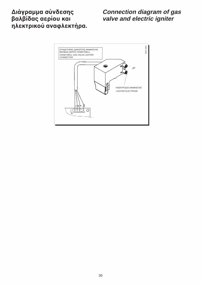
30
∆ιάγραµµα σύνδεσηςαλίδας αερίυ καιηλεκτρικύ ανα%λεκτήρα.
Connection diagram of gasvalve and electric igniter
0404
_260
1
ΗΛΕΚΤΡ%∆Ι% ΑΝΑΦΛΕdΗΣ
ΣΥΝ∆ΕΤΗΡΑΣ ∆ΙΑΚ%ΠΤΗΣ ΑΝΑΦΛΕdΗΣΒΑΛΒΙ∆Α ΑΕΡΙ%Υ HONEYWELLHONEYWELL GAS VALVE LIGHTERCONNECTOR
LIGHTER ELECTRODE
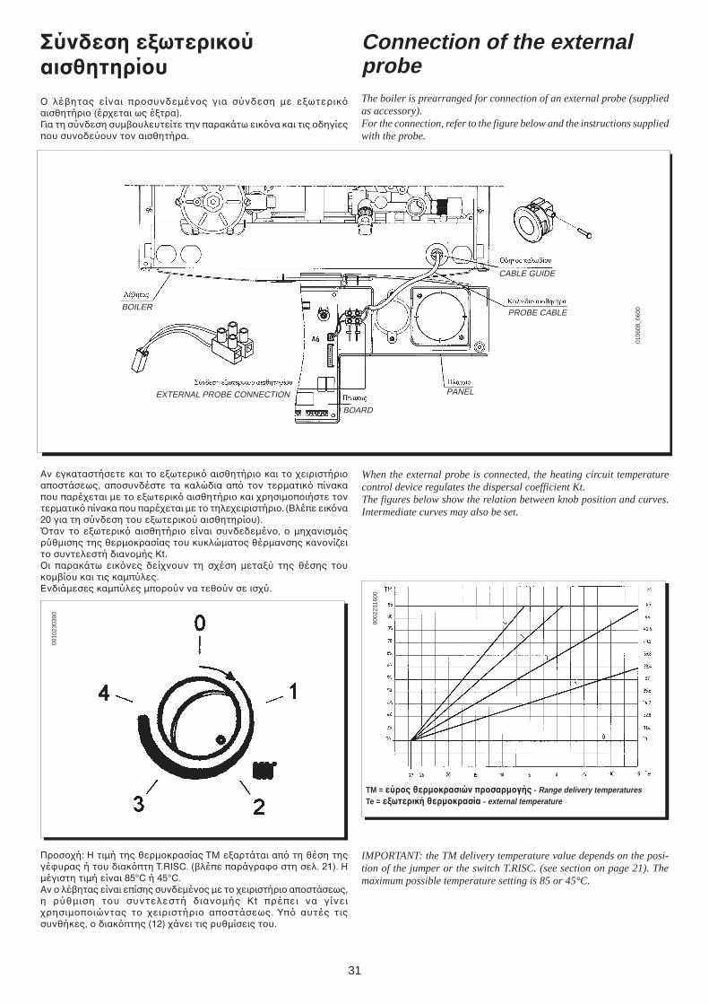
31
Σύνδεση εCωτερικύαισθητηρίυ% λέ!ητας είναι πρσυνδεµένς για σύνδεση µε εωτερικαισθητήρι (έρεται ως έτρα).Για τη σύνδεση συµ!υλευτείτε την παρακάτω εικνα και τις δηγίεςπυ συνδεύυν τν αισθητήρα.
Connection of the externalprobeThe boiler is prearranged for connection of an external probe (suppliedas accessory).For the connection, refer to the figure below and the instructions suppliedwith the probe.
BOILER
EXTERNAL PROBE CONNECTION
BOARD
PANEL
PROBE CABLE
CABLE GUIDE
0010
2303
00
0002
2316
00
TM = εύρς θερµκρασιών πρσαρµγής - Range delivery temperaturesTe = εCωτερική θερµκρασία - external temperature
IMPORTANT: the TM delivery temperature value depends on the posi-tion of the jumper or the switch T.RISC. (see section on page 21). Themaximum possible temperature setting is 85 or 45°C.
Πρσή: Η τιµή της θερµκρασίας ΤΜ εαρτάται απ τη θέση τηςγέυρας ή τυ διακπτη T.RISC. (!λέπε παράγρα στη σελ. 21). Ηµέγιστη τιµή είναι 85°C ή 45°C.Αν λέ!ητας είναι επίσης συνδεµένς µε τ ειριστήρι απστάσεως,η ρύθµιση τυ συντελεστή διανµής Kt πρέπει να γίνειρησιµπιώντας τ ειριστήρι απστάσεως. Υπ αυτές τιςσυνθήκες, διακπτης (12) άνει τις ρυθµίσεις τυ.
Αν εγκαταστήσετε και τ εωτερικ αισθητήρι και τ ειριστήριαπστάσεως, απσυνδέστε τα καλώδια απ τν τερµατικ πίνακαπυ παρέεται µε τ εωτερικ αισθητήρι και ρησιµπιήστε τντερµατικ πίνακα πυ παρέεται µε τ τηλεειριστήρι. (Βλέπε εικνα20 για τη σύνδεση τυ εωτερικύ αισθητηρίυ).Bταν τ εωτερικ αισθητήρι είναι συνδεδεµέν, µηανισµςρύθµισης της θερµκρασίας τυ κυκλώµατς θέρµανσης καννίειτ συντελεστή διανµής Kt.%ι παρακάτω εικνες δείνυν τη σέση µεταύ της θέσης τυκµ!ίυ και τις καµπύλες.Ενδιάµεσες καµπύλες µπρύν να τεθύν σε ισύ.
When the external probe is connected, the heating circuit temperaturecontrol device regulates the dispersal coefficient Kt.The figures below show the relation between knob position and curves.Intermediate curves may also be set.
0106
08_0
600
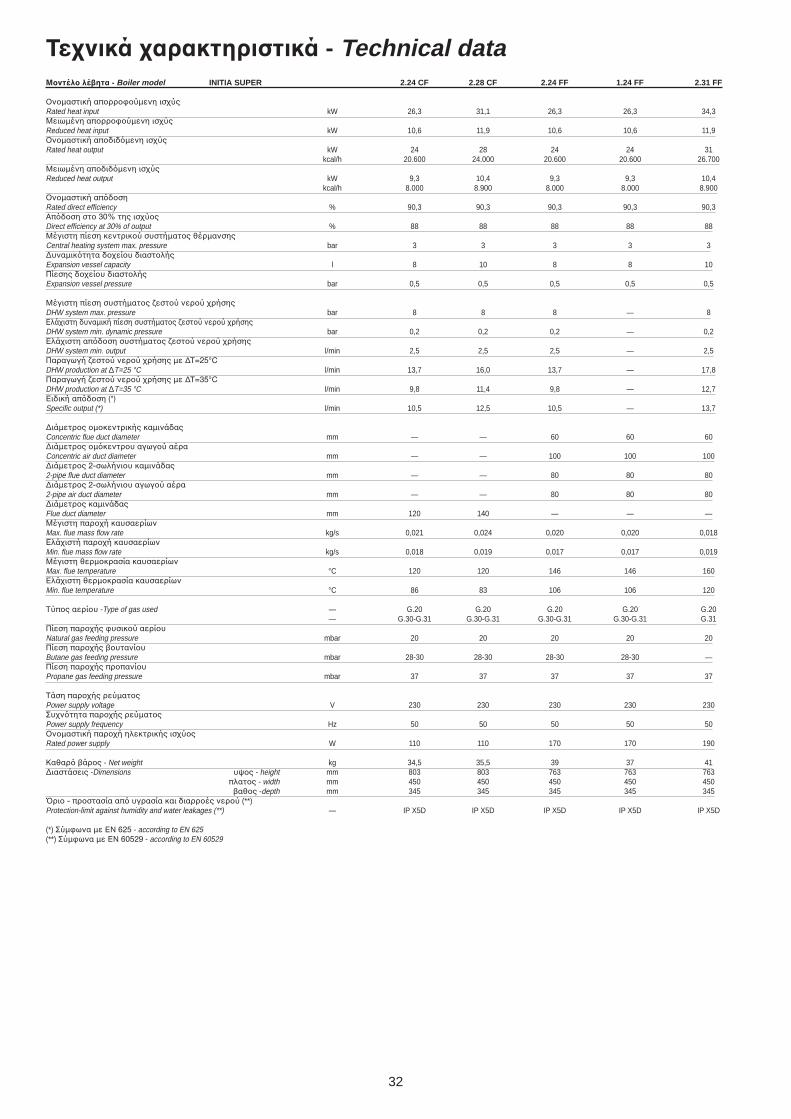
32
Τενικά αρακτηριστικά - Technical dataΜντέλ λέητα - Boiler model INITIA SUPER 2.24 CF 2.28 CF 2.24 FF 1.24 FF 2.31 FF
%νµαστική απρρύµενη ισύςRated heat input kW 26,3 31,1 26,3 26,3 34,3Μειωµένη απρρύµενη ισύςReduced heat input kW 10,6 11,9 10,6 10,6 11,9%νµαστική απδιδµενη ισύςRated heat output kW 24 28 24 24 31
kcal/h 20.600 24.000 20.600 20.600 26.700Μειωµένη απδιδµενη ισύςReduced heat output kW 9,3 10,4 9,3 9,3 10,4
kcal/h 8.000 8.900 8.000 8.000 8.900%νµαστική απδσηRated direct efficiency % 90,3 90,3 90,3 90,3 90,3Απδση στ 30% της ισύςDirect efficiency at 30% of output % 88 88 88 88 88Μέγιστη πίεση κεντρικύ συστήµατς θέρµανσηςCentral heating system max. pressure bar 3 3 3 3 3∆υναµικτητα δείυ διαστλήςExpansion vessel capacity l 8 10 8 8 10Πίεσης δείυ διαστλήςExpansion vessel pressure bar 0,5 0,5 0,5 0,5 0,5
Μέγιστη πίεση συστήµατς εστύ νερύ ρήσηςDHW system max. pressure bar 8 8 8 — 8Ελάιστη δυναµική πίεση συστήµατς εστύ νερύ ρήσηςDHW system min. dynamic pressure bar 0,2 0,2 0,2 — 0,2Ελάιστη απδση συστήµατς εστύ νερύ ρήσηςDHW system min. output l/min 2,5 2,5 2,5 — 2,5Παραγωγή εστύ νερύ ρήσης µε ∆Τ=25°CDHW production at ∆T=25 °C l/min 13,7 16,0 13,7 — 17,8Παραγωγή εστύ νερύ ρήσης µε ∆Τ=35°CDHW production at ∆T=35 °C l/min 9,8 11,4 9,8 — 12,7Ειδική απδση (*)Specific output (*) l/min 10,5 12,5 10,5 — 13,7
∆ιάµετρς µκεντρικής καµινάδαςConcentric flue duct diameter mm — — 60 60 60∆ιάµετρς µκεντρυ αγωγύ αέραConcentric air duct diameter mm — — 100 100 100∆ιάµετρς 2-σωλήνιυ καµινάδας2-pipe flue duct diameter mm — — 80 80 80∆ιάµετρς 2-σωλήνιυ αγωγύ αέρα2-pipe air duct diameter mm — — 80 80 80∆ιάµετρς καµινάδαςFlue duct diameter mm 120 140 — — —Μέγιστη παρή καυσαερίωνMax. flue mass flow rate kg/s 0,021 0,024 0,020 0,020 0,018Ελάιστή παρή καυσαερίωνMin. flue mass flow rate kg/s 0,018 0,019 0,017 0,017 0,019Μέγιστη θερµκρασία καυσαερίωνMax. flue temperature °C 120 120 146 146 160Ελάιστη θερµκρασία καυσαερίωνMin. flue temperature °C 86 83 106 106 120
Τύπς αερίυ -Type of gas used — G.20 G.20 G.20 G.20 G.20— G.30-G.31 G.30-G.31 G.30-G.31 G.30-G.31 G.31
Πίεση παρής υσικύ αερίυNatural gas feeding pressure mbar 20 20 20 20 20Πίεση παρής !υτανίυButane gas feeding pressure mbar 28-30 28-30 28-30 28-30 —Πίεση παρής πρπανίυPropane gas feeding pressure mbar 37 37 37 37 37
Τάση παρής ρεύµατςPower supply voltage V 230 230 230 230 230Συντητα παρής ρεύµατςPower supply frequency Hz 50 50 50 50 50%νµαστική παρή ηλεκτρικής ισύςRated power supply W 110 110 170 170 190
Καθαρ !άρς - Net weight kg 34,5 35,5 39 37 41∆ιαστάσεις -Dimensions υψς - height mm 803 803 763 763 763
πλατς - width mm 450 450 450 450 450!αθς -depth mm 345 345 345 345 345
Bρι - πρστασία απ υγρασία και διαρρές νερύ (**)Protection-limit against humidity and water leakages (**) — IP X5D IP X5D IP X5D IP X5D IP X5D
(*) Σύµωνα µε ΕΝ 625 - according to EN 625(**) Σύµωνα µε ΕΝ 60529 - according to EN 60529
33
No se deben dejar las partes del embalaje (bolsas de plástico, poliestireno,etc.) al alcance de niños, en cuanto que son potenciales fuentes de peligro.
As partes da embalagem (sacos de plástico, poliestireno, etc.) não devemser deixadas ao alcance das crianças porque podem constituir fontes deperigo.
Caro Cliente,
A nossa Empresa julga que esta nova caldeiraCHAPPEE vai satisfazer todas as Suasexigências.
A compra de um produto CHAPPEE garantequanto o Sr. espera: um bom funcionamento eum uso simples e racional.
Só pedimos o favor de não pôr de lado estasinstruções sem as ler, pois contêm informaçõesúteis para uma correcta e eficiente utilizaçãoda caldeira.
Estimado Cliente,
Nuestra Empresa opina que la nueva calderaCHAPPEE satisfará todas sus exigencias.
La compra de un producto CHAPPEEgarantiza lo que Ud. se espera: un buenfuncionamiento y un uso simple y racional.
Le pedimos que no ponga aparte estasinstrucciones sin leerlas: contienen infor-maciones útiles para una correcta y eficientegestión de su caldera.
code/código 923.606.1
Η CHAPPEE, δεσµευµενη να ελτιώνει συνεώς τα πρϊντα της έει τ δικαίωµα αλλαγής των τενικών αρακτηριστικών πυ αναέρνται εδώ ωρίς την υπρέωσης πρηγύµενηςπρειδπίησης. Αυτές ι δηγίες παρέυν στ ρήστη πληρρίες για τη ρήση και σε καµία περίπτωση δεν µπρύν να ερµηνευτύν διαρετικά απ πιδήπτε τρίτ µέρς.
CHAPPEE, in its commitment to constantly improve its products, reserves the right to alter the specifications contained herein at any time and without previous warning.These Instructions are only meant to provide consumers with use information and under no circumstance should they be construed as a contract with a third party.
Ediz. 1 - 07/04
157, Avenue Charles Floquet
93158 Le Blanc-Mesnil Cedex
Téléphone : 01 45 91 56 00 - Télécopie : 01 45 91 59 50
www.chappee.com
CHAPPEE, na constante acção de melhoramento dos produtos, reserva-se a possibilidade de modificar os dados expressos nesta documentação em qualquermomento e sem prévio aviso. A presente documentação é um suporte informativo e não considerável como contracto nos confrontos de terceiros.
CHAPPEE, en la constante acción de mejoramiento de los productos, se reserva la posibilidad de modificar los datos indicados en esta documentación en cualquiermomento y sin previo aviso. La presente documentación constituye un soporte informativo y no puede ser considerada un contrato hacia terceros.

INITIA SUPER
SPARE PARTS LIST -APRIL 2003-
SPARE PARTS LIST - APRIL 2006 -
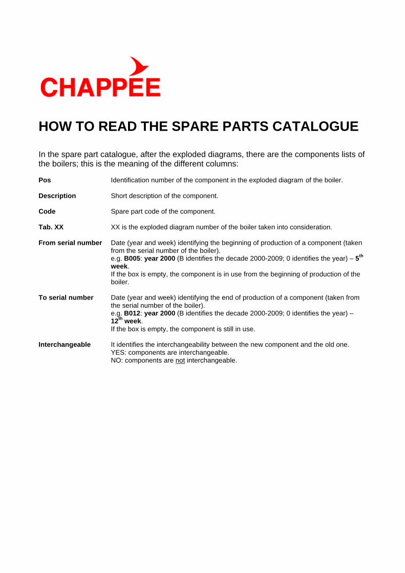
HOW TO READ THE SPARE PARTS CATALOGUE In the spare part catalogue, after the exploded diagrams, there are the components lists of the boilers; this is the meaning of the different columns: Pos Identification number of the component in the exploded diagram of the boiler. Description Short description of the component. Code Spare part code of the component. Tab. XX XX is the exploded diagram number of the boiler taken into consideration. From serial number Date (year and week) identifying the beginning of production of a component (taken
from the serial number of the boiler). e.g. B005: year 2000 (B identifies the decade 2000-2009; 0 identifies the year) – 5th week. If the box is empty, the component is in use from the beginning of production of the boiler.
To serial number Date (year and week) identifying the end of production of a component (taken from
the serial number of the boiler). e.g. B012: year 2000 (B identifies the decade 2000-2009; 0 identifies the year) – 12th week.
If the box is empty, the component is still in use. Interchangeable It identifies the interchangeability between the new component and the old one. YES: components are interchangeable. NO: components are not interchangeable.
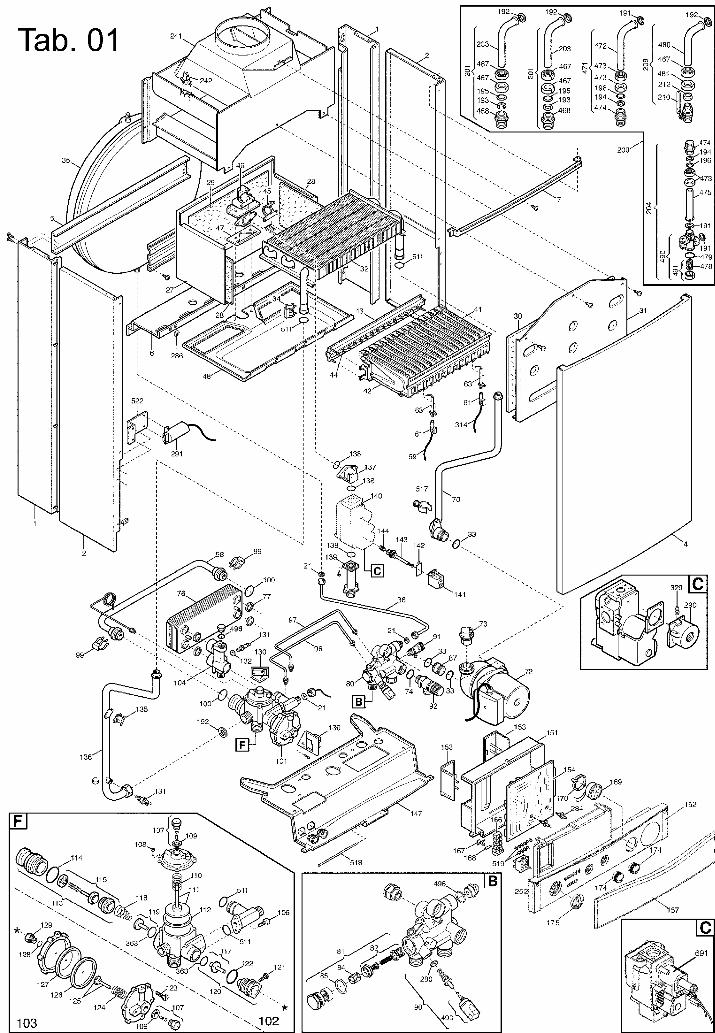

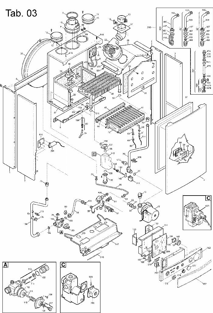
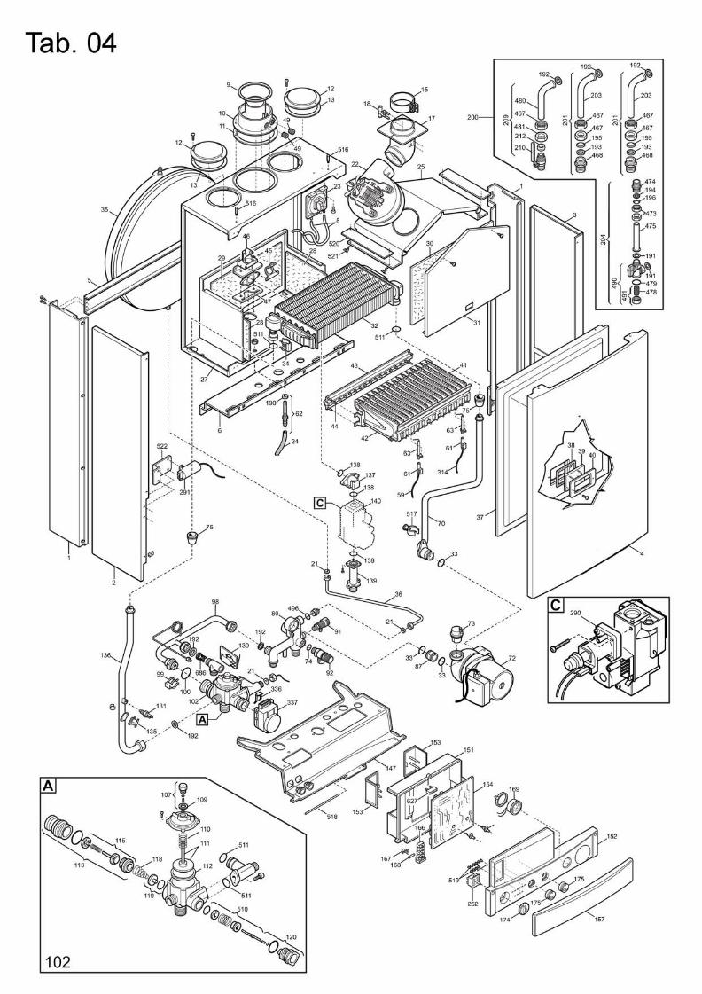
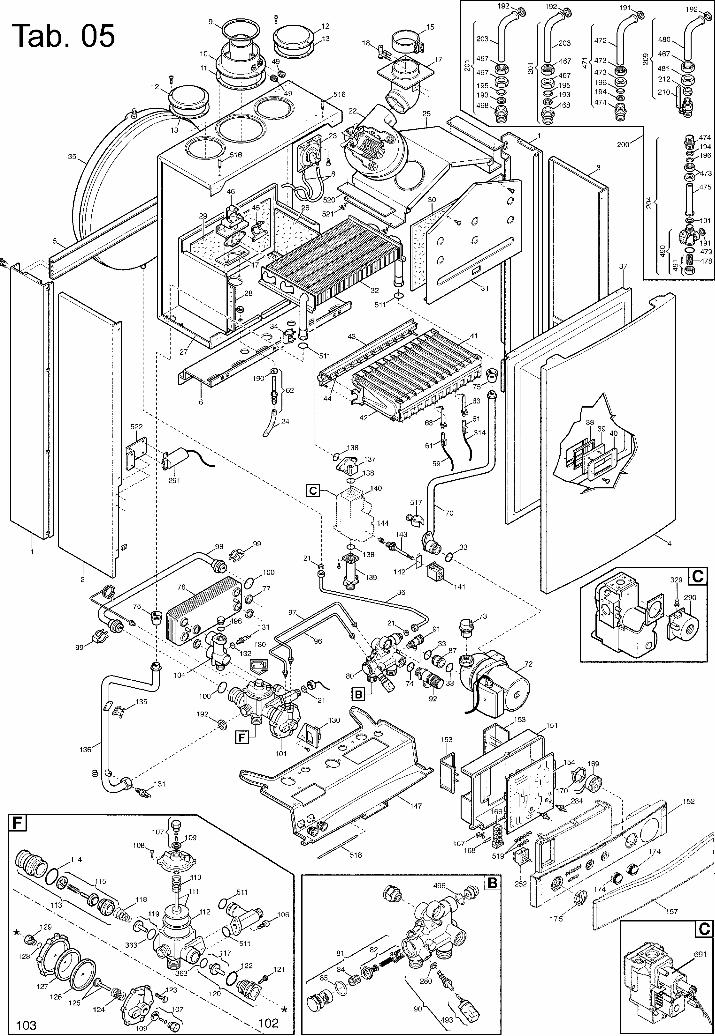
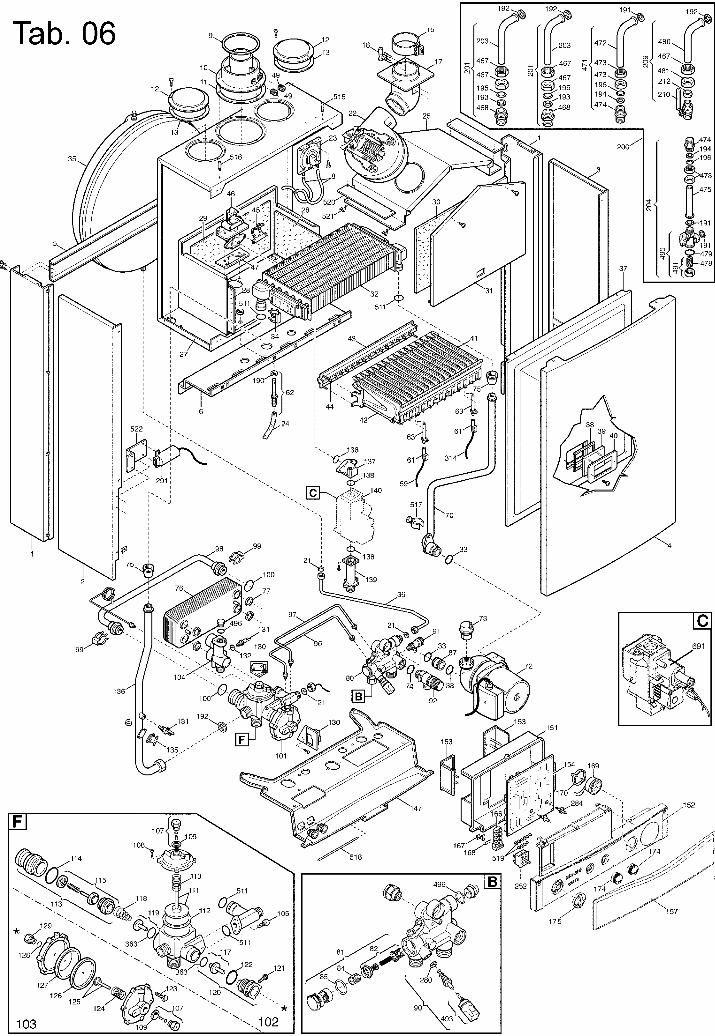
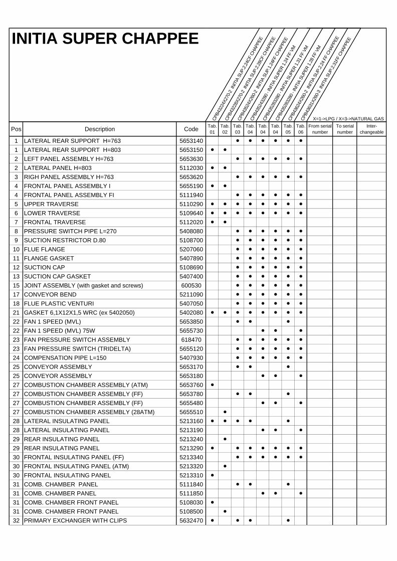
INITIA SUPER CHAPPEE
CPB4
3224
X270
-2 I
NITI
A SU
P.2.
24CF
CHA
PPEE
CPB4
3228
X270
-2 I
NITI
A SU
P.2.
28CF
CHA
PPEE
CPB4
3524
X260
-2 I
NITI
A SU
P.1.
24FF
CHA
PPEE
CPB4
3524
3280
- IN
ITIA
SUP
ER 1
.24
FF V
M
CPB4
3528
3280
- IN
ITIA
SUP
ER 1
.31
FF V
M
CPB4
3528
3280
- IN
ITIA
SUP
ER 1
.28
FF V
M
CPB4
3624
X260
-2 I
NITI
A SU
P.2.
24 F
F CH
APPE
E
CPB4
3631
X260
-3 I
NITI
A SU
P.2.
31FF
CHA
PPEE
X=1->LPG / X=3->NATURAL GAS
Pos Description Code Tab.01
Tab.02
Tab.03
Tab.04
Tab.04
Tab.04
Tab.05
Tab.06
From serial number
To serial number
Inter-changeable
1 LATERAL REAR SUPPORT H=763 5653140 l l l l l l
1 LATERAL REAR SUPPORT H=803 5653150 l l
2 LEFT PANEL ASSEMBLY H=763 5653630 l l l l l l
2 LATERAL PANEL H=803 5112030 l l
3 RIGH PANEL ASSEMBLY H=763 5653620 l l l l l l
4 FRONTAL PANEL ASSEMBLY I 5655190 l l
4 FRONTAL PANEL ASSEMBLY FI 5111940 l l l l l l
5 UPPER TRAVERSE 5110290 l l l l l l l l
6 LOWER TRAVERSE 5109640 l l l l l l l l
7 FRONTAL TRAVERSE 5112020 l l
8 PRESSURE SWITCH PIPE L=270 5408080 l l l l l l
9 SUCTION RESTRICTOR D.80 5108700 l l l l l l
10 FLUE FLANGE 5207060 l l l l l l
11 FLANGE GASKET 5407890 l l l l l l
12 SUCTION CAP 5108690 l l l l l l
13 SUCTION CAP GASKET 5407400 l l l l l l
15 JOINT ASSEMBLY (with gasket and screws) 600530 l l l l l l
17 CONVEYOR BEND 5211090 l l l l l l
18 FLUE PLASTIC VENTURI 5407050 l l l l l l
21 GASKET 6,1X12X1,5 WRC (ex 5402050) 5402080 l l l l l l l l
22 FAN 1 SPEED (MVL) 5653850 l l l
22 FAN 1 SPEED (MVL) 75W 5655730 l l l
23 FAN PRESSURE SWITCH ASSEMBLY 618470 l l l l l l
23 FAN PRESSURE SWITCH (TRIDELTA) 5655120 l l l l l l
24 COMPENSATION PIPE L=150 5407930 l l l l l l
25 CONVEYOR ASSEMBLY 5653170 l l l
25 CONVEYOR ASSEMBLY 5653180 l l l
27 COMBUSTION CHAMBER ASSEMBLY (ATM) 5653760 l
27 COMBUSTION CHAMBER ASSEMBLY (FF) 5653780 l l l
27 COMBUSTION CHAMBER ASSEMBLY (FF) 5655480 l l l
27 COMBUSTION CHAMBER ASSEMBLY (28ATM) 5655510 l
28 LATERAL INSULATING PANEL 5213160 l l l l l
28 LATERAL INSULATING PANEL 5213190 l l l
29 REAR INSULATING PANEL 5213240 l
29 REAR INSULATING PANEL 5213290 l l l l l l l
30 FRONTAL INSULATING PANEL (FF) 5213340 l l l l l l
30 FRONTAL INSULATING PANEL (ATM) 5213320 l
30 FRONTAL INSULATING PANEL 5213310 l
31 COMB. CHAMBER PANEL 5111840 l l l
31 COMB. CHAMBER PANEL 5111850 l l l
31 COMB. CHAMBER FRONT PANEL 5108030 l
31 COMB. CHAMBER FRONT PANEL 5108500 l
32 PRIMARY EXCHANGER WITH CLIPS 5632470 l l l l
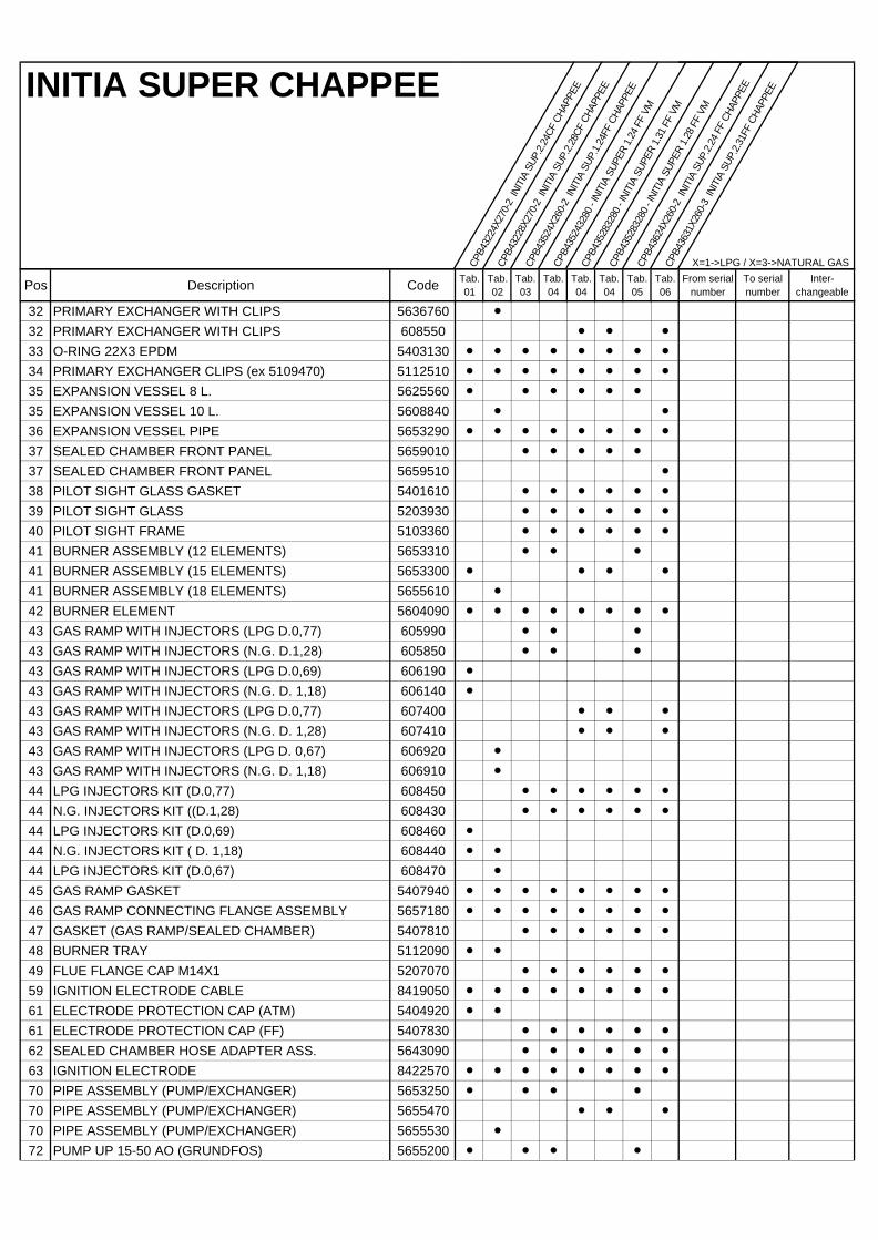
INITIA SUPER CHAPPEE
CPB4
3224
X270
-2 I
NITI
A SU
P.2.
24CF
CHA
PPEE
CPB4
3228
X270
-2 I
NITI
A SU
P.2.
28CF
CHA
PPEE
CPB4
3524
X260
-2 I
NITI
A SU
P.1.
24FF
CHA
PPEE
CPB4
3524
3280
- IN
ITIA
SUP
ER 1
.24
FF V
M
CPB4
3528
3280
- IN
ITIA
SUP
ER 1
.31
FF V
M
CPB4
3528
3280
- IN
ITIA
SUP
ER 1
.28
FF V
M
CPB4
3624
X260
-2 I
NITI
A SU
P.2.
24 F
F CH
APPE
E
CPB4
3631
X260
-3 I
NITI
A SU
P.2.
31FF
CHA
PPEE
X=1->LPG / X=3->NATURAL GAS
Pos Description Code Tab.01
Tab.02
Tab.03
Tab.04
Tab.04
Tab.04
Tab.05
Tab.06
From serial number
To serial number
Inter-changeable
32 PRIMARY EXCHANGER WITH CLIPS 5636760 l
32 PRIMARY EXCHANGER WITH CLIPS 608550 l l l
33 O-RING 22X3 EPDM 5403130 l l l l l l l l
34 PRIMARY EXCHANGER CLIPS (ex 5109470) 5112510 l l l l l l l l
35 EXPANSION VESSEL 8 L. 5625560 l l l l l l
35 EXPANSION VESSEL 10 L. 5608840 l l
36 EXPANSION VESSEL PIPE 5653290 l l l l l l l l
37 SEALED CHAMBER FRONT PANEL 5659010 l l l l l
37 SEALED CHAMBER FRONT PANEL 5659510 l
38 PILOT SIGHT GLASS GASKET 5401610 l l l l l l
39 PILOT SIGHT GLASS 5203930 l l l l l l
40 PILOT SIGHT FRAME 5103360 l l l l l l
41 BURNER ASSEMBLY (12 ELEMENTS) 5653310 l l l
41 BURNER ASSEMBLY (15 ELEMENTS) 5653300 l l l l
41 BURNER ASSEMBLY (18 ELEMENTS) 5655610 l
42 BURNER ELEMENT 5604090 l l l l l l l l
43 GAS RAMP WITH INJECTORS (LPG D.0,77) 605990 l l l
43 GAS RAMP WITH INJECTORS (N.G. D.1,28) 605850 l l l
43 GAS RAMP WITH INJECTORS (LPG D.0,69) 606190 l
43 GAS RAMP WITH INJECTORS (N.G. D. 1,18) 606140 l
43 GAS RAMP WITH INJECTORS (LPG D.0,77) 607400 l l l
43 GAS RAMP WITH INJECTORS (N.G. D. 1,28) 607410 l l l
43 GAS RAMP WITH INJECTORS (LPG D. 0,67) 606920 l
43 GAS RAMP WITH INJECTORS (N.G. D. 1,18) 606910 l
44 LPG INJECTORS KIT (D.0,77) 608450 l l l l l l
44 N.G. INJECTORS KIT ((D.1,28) 608430 l l l l l l
44 LPG INJECTORS KIT (D.0,69) 608460 l
44 N.G. INJECTORS KIT ( D. 1,18) 608440 l l
44 LPG INJECTORS KIT (D.0,67) 608470 l
45 GAS RAMP GASKET 5407940 l l l l l l l l
46 GAS RAMP CONNECTING FLANGE ASSEMBLY 5657180 l l l l l l l l
47 GASKET (GAS RAMP/SEALED CHAMBER) 5407810 l l l l l l
48 BURNER TRAY 5112090 l l
49 FLUE FLANGE CAP M14X1 5207070 l l l l l l
59 IGNITION ELECTRODE CABLE 8419050 l l l l l l l l
61 ELECTRODE PROTECTION CAP (ATM) 5404920 l l
61 ELECTRODE PROTECTION CAP (FF) 5407830 l l l l l l
62 SEALED CHAMBER HOSE ADAPTER ASS. 5643090 l l l l l l
63 IGNITION ELECTRODE 8422570 l l l l l l l l
70 PIPE ASSEMBLY (PUMP/EXCHANGER) 5653250 l l l l
70 PIPE ASSEMBLY (PUMP/EXCHANGER) 5655470 l l l
70 PIPE ASSEMBLY (PUMP/EXCHANGER) 5655530 l
72 PUMP UP 15-50 AO (GRUNDFOS) 5655200 l l l l
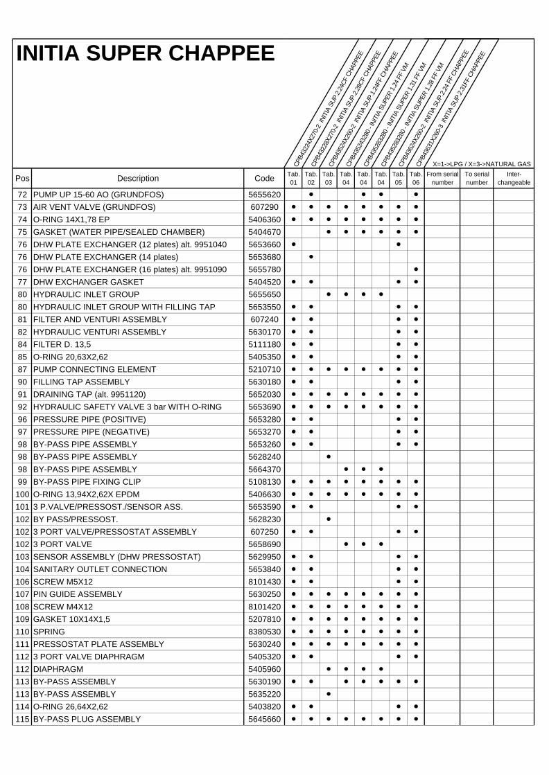
INITIA SUPER CHAPPEE
CPB4
3224
X270
-2 I
NITI
A SU
P.2.
24CF
CHA
PPEE
CPB4
3228
X270
-2 I
NITI
A SU
P.2.
28CF
CHA
PPEE
CPB4
3524
X260
-2 I
NITI
A SU
P.1.
24FF
CHA
PPEE
CPB4
3524
3280
- IN
ITIA
SUP
ER 1
.24
FF V
M
CPB4
3528
3280
- IN
ITIA
SUP
ER 1
.31
FF V
M
CPB4
3528
3280
- IN
ITIA
SUP
ER 1
.28
FF V
M
CPB4
3624
X260
-2 I
NITI
A SU
P.2.
24 F
F CH
APPE
E
CPB4
3631
X260
-3 I
NITI
A SU
P.2.
31FF
CHA
PPEE
X=1->LPG / X=3->NATURAL GAS
Pos Description Code Tab.01
Tab.02
Tab.03
Tab.04
Tab.04
Tab.04
Tab.05
Tab.06
From serial number
To serial number
Inter-changeable
72 PUMP UP 15-60 AO (GRUNDFOS) 5655620 l l l l
73 AIR VENT VALVE (GRUNDFOS) 607290 l l l l l l l l
74 O-RING 14X1,78 EP 5406360 l l l l l l l l
75 GASKET (WATER PIPE/SEALED CHAMBER) 5404670 l l l l l l
76 DHW PLATE EXCHANGER (12 plates) alt. 9951040 5653660 l l
76 DHW PLATE EXCHANGER (14 plates) 5653680 l
76 DHW PLATE EXCHANGER (16 plates) alt. 9951090 5655780 l
77 DHW EXCHANGER GASKET 5404520 l l l l
80 HYDRAULIC INLET GROUP 5655650 l l l l
80 HYDRAULIC INLET GROUP WITH FILLING TAP 5653550 l l l l
81 FILTER AND VENTURI ASSEMBLY 607240 l l l l
82 HYDRAULIC VENTURI ASSEMBLY 5630170 l l l l
84 FILTER D. 13,5 5111180 l l l l
85 O-RING 20,63X2,62 5405350 l l l l
87 PUMP CONNECTING ELEMENT 5210710 l l l l l l l l
90 FILLING TAP ASSEMBLY 5630180 l l l l
91 DRAINING TAP (alt. 9951120) 5652030 l l l l l l l l
92 HYDRAULIC SAFETY VALVE 3 bar WITH O-RING 5653690 l l l l l l l l
96 PRESSURE PIPE (POSITIVE) 5653280 l l l l
97 PRESSURE PIPE (NEGATIVE) 5653270 l l l l
98 BY-PASS PIPE ASSEMBLY 5653260 l l l l
98 BY-PASS PIPE ASSEMBLY 5628240 l
98 BY-PASS PIPE ASSEMBLY 5664370 l l l
99 BY-PASS PIPE FIXING CLIP 5108130 l l l l l l l l
100 O-RING 13,94X2,62X EPDM 5406630 l l l l l l l l
101 3 P.VALVE/PRESSOST./SENSOR ASS. 5653590 l l l l
102 BY PASS/PRESSOST. 5628230 l
102 3 PORT VALVE/PRESSOSTAT ASSEMBLY 607250 l l l l
102 3 PORT VALVE 5658690 l l l
103 SENSOR ASSEMBLY (DHW PRESSOSTAT) 5629950 l l l l
104 SANITARY OUTLET CONNECTION 5653840 l l l l
106 SCREW M5X12 8101430 l l l l
107 PIN GUIDE ASSEMBLY 5630250 l l l l l l l l
108 SCREW M4X12 8101420 l l l l l l l l
109 GASKET 10X14X1,5 5207810 l l l l l l l l
110 SPRING 8380530 l l l l l l l l
111 PRESSOSTAT PLATE ASSEMBLY 5630240 l l l l l l l l
112 3 PORT VALVE DIAPHRAGM 5405320 l l l l
112 DIAPHRAGM 5405960 l l l l
113 BY-PASS ASSEMBLY 5630190 l l l l l l l
113 BY-PASS ASSEMBLY 5635220 l
114 O-RING 26,64X2,62 5403820 l l l l
115 BY-PASS PLUG ASSEMBLY 5645660 l l l l l l l l
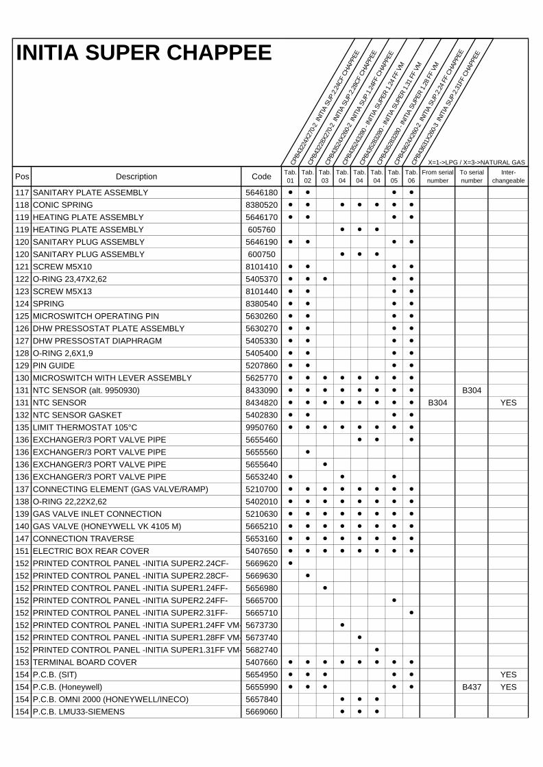
INITIA SUPER CHAPPEE
CPB4
3224
X270
-2 I
NITI
A SU
P.2.
24CF
CHA
PPEE
CPB4
3228
X270
-2 I
NITI
A SU
P.2.
28CF
CHA
PPEE
CPB4
3524
X260
-2 I
NITI
A SU
P.1.
24FF
CHA
PPEE
CPB4
3524
3280
- IN
ITIA
SUP
ER 1
.24
FF V
M
CPB4
3528
3280
- IN
ITIA
SUP
ER 1
.31
FF V
M
CPB4
3528
3280
- IN
ITIA
SUP
ER 1
.28
FF V
M
CPB4
3624
X260
-2 I
NITI
A SU
P.2.
24 F
F CH
APPE
E
CPB4
3631
X260
-3 I
NITI
A SU
P.2.
31FF
CHA
PPEE
X=1->LPG / X=3->NATURAL GAS
Pos Description Code Tab.01
Tab.02
Tab.03
Tab.04
Tab.04
Tab.04
Tab.05
Tab.06
From serial number
To serial number
Inter-changeable
117 SANITARY PLATE ASSEMBLY 5646180 l l l l
118 CONIC SPRING 8380520 l l l l l l l
119 HEATING PLATE ASSEMBLY 5646170 l l l l
119 HEATING PLATE ASSEMBLY 605760 l l l
120 SANITARY PLUG ASSEMBLY 5646190 l l l l
120 SANITARY PLUG ASSEMBLY 600750 l l l
121 SCREW M5X10 8101410 l l l l
122 O-RING 23,47X2,62 5405370 l l l l l
123 SCREW M5X13 8101440 l l l l
124 SPRING 8380540 l l l l
125 MICROSWITCH OPERATING PIN 5630260 l l l l
126 DHW PRESSOSTAT PLATE ASSEMBLY 5630270 l l l l
127 DHW PRESSOSTAT DIAPHRAGM 5405330 l l l l
128 O-RING 2,6X1,9 5405400 l l l l
129 PIN GUIDE 5207860 l l l l
130 MICROSWITCH WITH LEVER ASSEMBLY 5625770 l l l l l l l l
131 NTC SENSOR (alt. 9950930) 8433090 l l l l l l l l B304131 NTC SENSOR 8434820 l l l l l l l l B304 YES132 NTC SENSOR GASKET 5402830 l l l l
135 LIMIT THERMOSTAT 105°C 9950760 l l l l l l l l
136 EXCHANGER/3 PORT VALVE PIPE 5655460 l l l
136 EXCHANGER/3 PORT VALVE PIPE 5655560 l
136 EXCHANGER/3 PORT VALVE PIPE 5655640 l
136 EXCHANGER/3 PORT VALVE PIPE 5653240 l l l
137 CONNECTING ELEMENT (GAS VALVE/RAMP) 5210700 l l l l l l l l
138 O-RING 22,22X2,62 5402010 l l l l l l l l
139 GAS VALVE INLET CONNECTION 5210630 l l l l l l l l
140 GAS VALVE (HONEYWELL VK 4105 M) 5665210 l l l l l l l l
147 CONNECTION TRAVERSE 5653160 l l l l l l l l
151 ELECTRIC BOX REAR COVER 5407650 l l l l l l l l
152 PRINTED CONTROL PANEL -INITIA SUPER2.24CF- 5669620 l
152 PRINTED CONTROL PANEL -INITIA SUPER2.28CF- 5669630 l
152 PRINTED CONTROL PANEL -INITIA SUPER1.24FF- 5656980 l
152 PRINTED CONTROL PANEL -INITIA SUPER2.24FF- 5665700 l
152 PRINTED CONTROL PANEL -INITIA SUPER2.31FF- 5665710 l
152 PRINTED CONTROL PANEL -INITIA SUPER1.24FF VM- 5673730 l
152 PRINTED CONTROL PANEL -INITIA SUPER1.28FF VM- 5673740 l
152 PRINTED CONTROL PANEL -INITIA SUPER1.31FF VM- 5682740 l
153 TERMINAL BOARD COVER 5407660 l l l l l l l l
154 P.C.B. (SIT) 5654950 l l l l l YES154 P.C.B. (Honeywell) 5655990 l l l l l B437 YES154 P.C.B. OMNI 2000 (HONEYWELL/INECO) 5657840 l l l
154 P.C.B. LMU33-SIEMENS 5669060 l l l
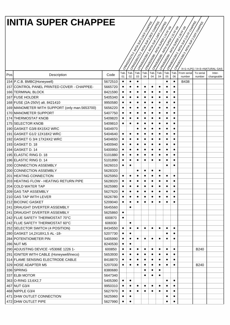
INITIA SUPER CHAPPEE
CPB4
3224
X270
-2 I
NITI
A SU
P.2.
24CF
CHA
PPEE
CPB4
3228
X270
-2 I
NITI
A SU
P.2.
28CF
CHA
PPEE
CPB4
3524
X260
-2 I
NITI
A SU
P.1.
24FF
CHA
PPEE
CPB4
3524
3280
- IN
ITIA
SUP
ER 1
.24
FF V
M
CPB4
3528
3280
- IN
ITIA
SUP
ER 1
.31
FF V
M
CPB4
3528
3280
- IN
ITIA
SUP
ER 1
.28
FF V
M
CPB4
3624
X260
-2 I
NITI
A SU
P.2.
24 F
F CH
APPE
E
CPB4
3631
X260
-3 I
NITI
A SU
P.2.
31FF
CHA
PPEE
X=1->LPG / X=3->NATURAL GAS
Pos Description Code Tab.01
Tab.02
Tab.03
Tab.04
Tab.04
Tab.04
Tab.05
Tab.06
From serial number
To serial number
Inter-changeable
154 P.C.B. BMBC(Honeywell) 5672510 l l l l l B438157 CONTROL PANEL PRINTED COVER - CHAPPEE- 5665720 l l l l l l l l
166 TERMINAL BLOCK 8421590 l l l l l l l l
167 FUSE HOLDER 5405340 l l l l l l l l
168 FUSE (2A-250V) alt. 8421410 9950580 l l l l l l l l
169 MANOMETER WITH SUPPORT (only man.5653700) 5656220 l l l l l l l l
170 MANOMETER SUPPORT 5407750 l l l l l l l l
174 THERMOSTAT KNOB 5409820 l l l l l l l l
175 SELECTOR KNOB 5409810 l l l l l l l l
190 GASKET G3/8 8X15X2 WRC 5404970 l l l l l l
191 GASKET G1/2 12X18X2 WRC 5404640 l l l l l l l l
192 GASKET G 3/4 17X24X2 WRC 5404650 l l l l l l l l
193 GASKET D. 18 5400940 l l l l l l l l
194 GASKET D. 14 5400950 l l l l l l l l
195 ELASTIC RING D. 18 5101880 l l l l l l l l
196 ELASTIC RING D. 14 5101890 l l l l l l l l
200 CONNECTION ASSEMBLY 5626010 l l l l
200 CONNECTION ASSEMBLY 5628320 l l l l
201 HEATING CONNECTION 5625950 l l l l l l l l
203 HEATING FLOW - HEATING RETURN PIPE 5628020 l l l l l l l l
204 COLD WATER TAP 5625980 l l l l l l l l
209 GAS TAP ASSEMBLY 5627620 l l l l l l l l
210 GAS TAP WITH LEVER 5626780 l l l l l l l l
212 BICONIC GASKET 5209040 l l l l l l l l
241 DRAUGHT DIVERTER ASSEMBLY 5645560 l
241 DRAUGHT DIVERTER ASSEMBLY 5625860 l
242 FLUE SAFETY THERMOSTAT 70°C 600870 l
242 FLUE SAFETY THERMOSTAT 60°C 606930 l
252 SELECTOR SWITCH (4 POSITION) 8434550 l l l l l l l l
280 GASKET 14,2X18X1,5 AL -18- 5207730 l l l l
284 POTENTIOMETER PIN 5405990 l l l l l l l l
286 NUT M5 8240530 l l
290 ADJUSTING DEVICE -V5306E 1226 1- 600850 l l l l l l l l B240291 IGNITER WITH CABLE (Honeywell/Ineco) 5653930 l l l l l l l l
314 FLAME SENSING ELECTRODE CABLE 8418870 l l l l l l l l
329 HOSE ADAPTER M5 5207030 l l l l l l l l B240336 SPRING 8380680 l l l
337 ELBI MOTOR 5647340 l l l
363 O-RING 13,6X2,7 5405390 l l l l
467 NUT G3/4 9950310 l l l l l l l l
468 NIPPLE G3/4 5627970 l l l l l l l l
471 DHW OUTLET CONNECTION 5625960 l l l l
472 DHW OUTLET PIPE 5627990 l l l l
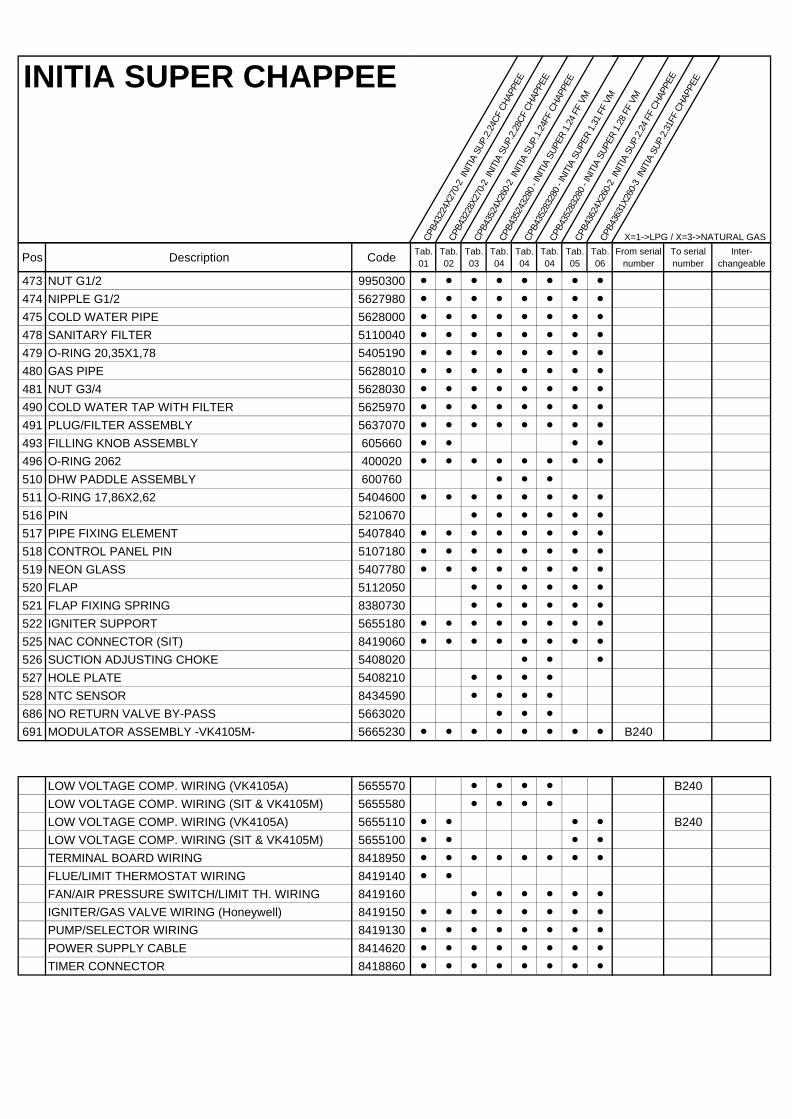
INITIA SUPER CHAPPEE
CPB4
3224
X270
-2 I
NITI
A SU
P.2.
24CF
CHA
PPEE
CPB4
3228
X270
-2 I
NITI
A SU
P.2.
28CF
CHA
PPEE
CPB4
3524
X260
-2 I
NITI
A SU
P.1.
24FF
CHA
PPEE
CPB4
3524
3280
- IN
ITIA
SUP
ER 1
.24
FF V
M
CPB4
3528
3280
- IN
ITIA
SUP
ER 1
.31
FF V
M
CPB4
3528
3280
- IN
ITIA
SUP
ER 1
.28
FF V
M
CPB4
3624
X260
-2 I
NITI
A SU
P.2.
24 F
F CH
APPE
E
CPB4
3631
X260
-3 I
NITI
A SU
P.2.
31FF
CHA
PPEE
X=1->LPG / X=3->NATURAL GAS
Pos Description Code Tab.01
Tab.02
Tab.03
Tab.04
Tab.04
Tab.04
Tab.05
Tab.06
From serial number
To serial number
Inter-changeable
473 NUT G1/2 9950300 l l l l l l l l
474 NIPPLE G1/2 5627980 l l l l l l l l
475 COLD WATER PIPE 5628000 l l l l l l l l
478 SANITARY FILTER 5110040 l l l l l l l l
479 O-RING 20,35X1,78 5405190 l l l l l l l l
480 GAS PIPE 5628010 l l l l l l l l
481 NUT G3/4 5628030 l l l l l l l l
490 COLD WATER TAP WITH FILTER 5625970 l l l l l l l l
491 PLUG/FILTER ASSEMBLY 5637070 l l l l l l l l
493 FILLING KNOB ASSEMBLY 605660 l l l l
496 O-RING 2062 400020 l l l l l l l l
510 DHW PADDLE ASSEMBLY 600760 l l l
511 O-RING 17,86X2,62 5404600 l l l l l l l l
516 PIN 5210670 l l l l l l
517 PIPE FIXING ELEMENT 5407840 l l l l l l l l
518 CONTROL PANEL PIN 5107180 l l l l l l l l
519 NEON GLASS 5407780 l l l l l l l l
520 FLAP 5112050 l l l l l l
521 FLAP FIXING SPRING 8380730 l l l l l l
522 IGNITER SUPPORT 5655180 l l l l l l l l
525 NAC CONNECTOR (SIT) 8419060 l l l l l l l l
526 SUCTION ADJUSTING CHOKE 5408020 l l l
527 HOLE PLATE 5408210 l l l l
528 NTC SENSOR 8434590 l l l l
686 NO RETURN VALVE BY-PASS 5663020 l l l
691 MODULATOR ASSEMBLY -VK4105M- 5665230 l l l l l l l l B240
LOW VOLTAGE COMP. WIRING (VK4105A) 5655570 l l l l B240LOW VOLTAGE COMP. WIRING (SIT & VK4105M) 5655580 l l l l
LOW VOLTAGE COMP. WIRING (VK4105A) 5655110 l l l l B240LOW VOLTAGE COMP. WIRING (SIT & VK4105M) 5655100 l l l l
TERMINAL BOARD WIRING 8418950 l l l l l l l l
FLUE/LIMIT THERMOSTAT WIRING 8419140 l l
FAN/AIR PRESSURE SWITCH/LIMIT TH. WIRING 8419160 l l l l l l
IGNITER/GAS VALVE WIRING (Honeywell) 8419150 l l l l l l l l
PUMP/SELECTOR WIRING 8419130 l l l l l l l l
POWER SUPPLY CABLE 8414620 l l l l l l l l
TIMER CONNECTOR 8418860 l l l l l l l l


BAXI S.p.A. Via Trozzetti, 20 36061 BASSANO DEL GRAPPA (VI) ITALY Tel. +390424517111 Telefax +390424517379 E-mail. [email protected]