STRUCTURAL CALCULATIONS - Cloud Object … Pad Foundation ..... 26 10. Concrete Frame Design ........
56
© MasterSeries PowerPad - Project Title PowerPadSampleOutput.docx © Civil and Structural Computer Services Limited, 1 Circular Road, Newtownabbey, Co. Antrim BT37 0RA, Tel : 028 9036 5950 Fax : 028 9036 5102 STRUCTURAL CALCULATIONS Using MASTERSERIES POWERPAD Project Name1 Address 1 Address 2 Address 3 ARCHITECT ARCHITECT NAME Location Location Location STRUCTURAL ENGINEERS MASTERSERIES USER COMPANY To place your details here please copy your custom user title block file to the MasterSeries application directory. Fax: (028) 9036 5102 PROJECT NO: P12345 December 2016 V.A.T. Reg. No. ___ ____ __
Transcript of STRUCTURAL CALCULATIONS - Cloud Object … Pad Foundation ..... 26 10. Concrete Frame Design ........
© MasterSeries PowerPad - Project Title PowerPadSampleOutput.docx
© Civil and Structural Computer Services Limited, 1 Circular Road, Newtownabbey, Co. Antrim BT37 0RA, Tel : 028 9036 5950 Fax : 028 9036 5102
STRUCTURAL CALCULATIONS Using
MASTERSERIES POWERPAD
Project Name1 Address 1 Address 2 Address 3
ARCHITECT
ARCHITECT NAME Location Location Location
STRUCTURAL ENGINEERS
MASTERSERIES USER COMPANY To place your details here please copy your custom
user title block file to the MasterSeries application directory.
Fax: (028) 9036 5102
PROJECT NO: P12345
December 2016
V.A.T. Reg. No. ___ ____ __
© MasterSeries PowerPad - Project Title PowerPadSampleOutput.docx
Your logo here
MasterSeries Sales Team 3 Castle Street
Carrickfergus
Co. Antrim BT38 7BE
Job ref : J12345/S
Sheet : Sheet Ref / 2 - Page | 2
Made By : ATW
Date : 22 August 2017 Version 2017.08
Checked :
Approved : Tel : 028 9036 5950
© Civil and Structural Computer Services Limited, 1 Circular Road, Newtownabbey, Co. Antrim BT37 0RA, Tel : 028 9036 5950 Fax : 028 9036 5102
Table of Contents
1. Table of Contents ...................................................................................................................................... 2
2. Steel Beam ................................................................................................................................................ 3
3. Timber Floor Joist Design.......................................................................................................................... 5
4. Timber Flitch Beam Design ....................................................................................................................... 6
5. Timber Attic Truss Design ......................................................................................................................... 8
6. 2 Span Portal Frame ............................................................................................................................... 11
7. Portal Connections – Full Output ............................................................................................................ 17
8. Portal Connections Summerised Output ................................................................................................. 23
9. Portal Pad Foundation ............................................................................................................................. 26
10. Concrete Frame Design .......................................................................................................................... 28
11. Bar Schedule ........................................................................................................................................... 36
12. Composite Beam Design ......................................................................................................................... 41
13. Masonry Walls ......................................................................................................................................... 44
14. Retaining Walls ........................................................................................................................................ 47
15. Pile Cap Design ....................................................................................................................................... 50
16. Two-Way Slab ......................................................................................................................................... 52
17. Simple continuous Slab ........................................................................................................................... 53
18. Typical PowerPad Frames ...................................................................................................................... 54
© MasterSeries PowerPad - Project Title PowerPadSampleOutput.docx
Your logo here
MasterSeries Sales Team 3 Castle Street
Carrickfergus
Co. Antrim BT38 7BE
Job ref : J12345/S
Sheet : Sheet Ref / 3 - Page | 3
Made By : ATW
Date : 22 August 2017 Version 2017.08
Checked :
Approved : Tel : 028 9036 5950
© Civil and Structural Computer Services Limited, 1 Circular Road, Newtownabbey, Co. Antrim BT37 0RA, Tel : 028 9036 5950 Fax : 028 9036 5102
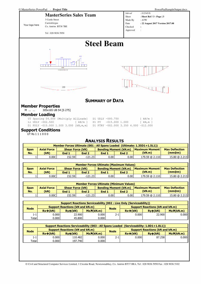
Steel Beam
SUMMARY OF DATA Member Properties M ... ... 305x165 UB 54 [S 275]
Member Loading UT Spacing 04.000 [Multiply AllLoads] D1 UDLY -000.750 [ kN/m ]
L1 UDLY -002.500 [ kN/m ] D1 PY -015.000 1.000 [ kN,m ]
D1 PDLY -015.000 1.500 3.000 [kN,m,m] D1 PTRY -002.000 3.350 4.000 -012.000
Support Conditions UT Rs 1 1 1 0 0 0
ANALYSIS RESULTS Member Forces Ultimate (001 : All Spans Loaded (Ultimate: 1.35D1+1.5L1))
Span
No.
Axial Force
(kN)
Shear Force (kN) Bending Moment (kN.m) Maximum Moment (kN.m)
Max Deflection (mm@m) End 1 End 2 End 1 End 2
1 0.00C 152.59 -121.23 0.00 0.00 179.59 @ 2.110 15.80 @ 2.213
Member Forces Ultimate (Maximum Values)
Span
No.
Axial Force
(kN)
Shear Force (kN) Bending Moment (kN.m) Maximum Moment (kN.m)
Max Deflection (mm@m) End 1 End 2 End 1 End 2
1 0.00C 152.59 -121.23 0.00 0.00 179.59 @ 2.110 15.80 @ 2.213
Member Forces Ultimate (Minimum Values)
Span
No.
Axial Force
(kN)
Shear Force (kN) Bending Moment (kN.m) Maximum Moment (kN.m)
Max Deflection (mm@m) End 1 End 2 End 1 End 2
1 0.00C 152.59 -121.23 0.00 0.00 179.59 @ 2.110 15.80 @ 2.213
Support Reactions Serviceability (002 : Live Only (Serviceability))
Node Support Reactions (kN and kN.m)
Node Support Reactions (kN and kN.m)
Rx�(kN) Ry�(kN) Mz�(kN.m) Rx�(kN) Ry�(kN) Mz�(kN.m)
1-1 0.000 22.900 0.000 2-1 0.000 22.900 0.000 Total 0.000 45.800 0.000
Support Reactions Serviceability (003 : All Spans Loaded (Serviceability: 1.0D1+1.0L1))
Node Support Reactions (kN and kN.m)
Node Support Reactions (kN and kN.m)
Rx�(kN) Ry�(kN) Mz�(kN.m) Rx�(kN) Ry�(kN) Mz�(kN.m)
1-1 0.000 110.482 0.000 2-1 0.000 87.258 0.000 Total 0.000 197.740 0.000
© MasterSeries PowerPad - Project Title PowerPadSampleOutput.docx
Your logo here
MasterSeries Sales Team 3 Castle Street
Carrickfergus
Co. Antrim BT38 7BE
Job ref : J12345/S
Sheet : Sheet Ref / 4 - Page | 4
Made By : ATW
Date : 22 August 2017 Version 2017.08
Checked :
Approved : Tel : 028 9036 5950
© Civil and Structural Computer Services Limited, 1 Circular Road, Newtownabbey, Co. Antrim BT37 0RA, Tel : 028 9036 5950 Fax : 028 9036 5102
Support Reactions Serviceability (Maximum Values)
Node Support Reactions (kN and kN.m)
Node Support Reactions (kN and kN.m)
Rx�(kN) Ry�(kN) Mz�(kN.m) Rx�(kN) Ry�(kN) Mz�(kN.m)
1-1 0.000 110.482 0.000 2-1 0.000 87.258 0.000 Total 0.000 197.740 0.000
Support Reactions Serviceability (Minimum Values)
Node Support Reactions (kN and kN.m)
Node Support Reactions (kN and kN.m)
Rx�(kN) Ry�(kN) Mz�(kN.m) Rx�(kN) Ry�(kN) Mz�(kN.m)
1-1 0.000 22.900 0.000 2-1 0.000 22.900 0.000 Total 0.000 45.800 0.000
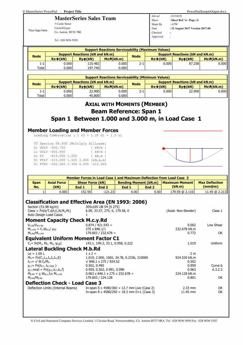
AXIAL WITH MOMENTS (MEMBER)
Beam Reference: Span 1
Span 1 Between 1.000 and 3.000 m, in Load Case 1
Member Loading and Member Forces Loading Combination : 1 UT + 1.35 D1 + 1.5 L1
UT Spacing 04.000 [Multiply AllLoads]
D1 UDLY -000.750 [ kN/m ]
L1 UDLY -002.500 [ kN/m ]
D1 PY -015.000 1.000 [ kN,m ]
D1 PDLY -015.000 1.500 3.000 [kN,m,m]
D1 PTRY -002.000 3.350 4.000 -012.000
Member Forces in Load Case 1 and Maximum Deflection from Load Case 3
Span
No.
Axial Force
(kN)
Shear Force (kN) Bending Moment (kN.m) Maximum Moment (kN.m)
Max Deflection (mm@m) End 1 End 2 End 1 End 2
1 0.00C 152.59 -121.23 0.00 0.00 179.59 @ 2.110 11.45 @ 2.213
Classification and Effective Area (EN 1993: 2006) Section (53.98 kg/m) 305x165 UB 54 [S 275] Class = Fn(b/T,d/t,fy,N,My,Mz) 6.09, 33.57, 275, 0, 179.58, 0 (Axial: Non-Slender) Class 1 Auto Design Load Cases 1
Moment Capacity Check M.c.y.Rd Vy.Ed/Vpl.y.Rd 0.874 / 421.543 = 0.002 Low Shear Mc.y.Rd = fy.Wpl.y/ γM0 275 x 846.1/1 232.678 kN.m My.Ed/Mc.y.Rd 179.603 / 232.678 = 0.772 OK
Equivalent Uniform Moment Factor C1 C1= fn(M1, M2, Mo, ψ,µ) 143.1, 149.3, 33.1, 0.958, 0.222 1.019 Uniform
Lateral Buckling Check M.b.Rd Le = 1.00 L 1 x 2 = 2 m Mcr= Fn(C1,Le,Iz,It,Iw,E) 1.019, 2.000, 1065, 34.78, 0.2336, 210000 924.520 kN.m λLT= √ W.fy/Mcr √ 846.1 x 275 / 924.52 0.502 χLT= Fn(λLT, λLT5950 ) 0.502, 0.495 0.959 Curve b χLT.mod = Fn(χLT,λLT,kc,f) 0.959, 0.502, 0.991, 0.996 0.963 6.3.2.3 Mb.Rd = χ Wpl.y.fy≤ Mc.y.Rd 0.963 x 846.1 x 275 ≤ 232.678 = 224.128 kN.m My.Ed/Mb.Rd 179.603 / 224.128 0.801 OK
Deflection Check - Load Case 3 Deflection Limits (Internal Beams) In-span δ ≤ 4580/360 = 12.7 mm Live (Case 2) 2.33 mm OK In-span δ ≤ 4580/250 = 18.3 mm D+L (Case 3) 11.45 mm OK
© MasterSeries PowerPad - Project Title PowerPadSampleOutput.docx
Your logo here
MasterSeries Sales Team 3 Castle Street
Carrickfergus
Co. Antrim BT38 7BE
Job ref : J12345/S
Sheet : Sheet Ref / 5 - Page | 5
Made By : ATW
Date : 22 August 2017 Version 2017.08
Checked :
Approved : Tel : 028 9036 5950
© Civil and Structural Computer Services Limited, 1 Circular Road, Newtownabbey, Co. Antrim BT37 0RA, Tel : 028 9036 5950 Fax : 028 9036 5102
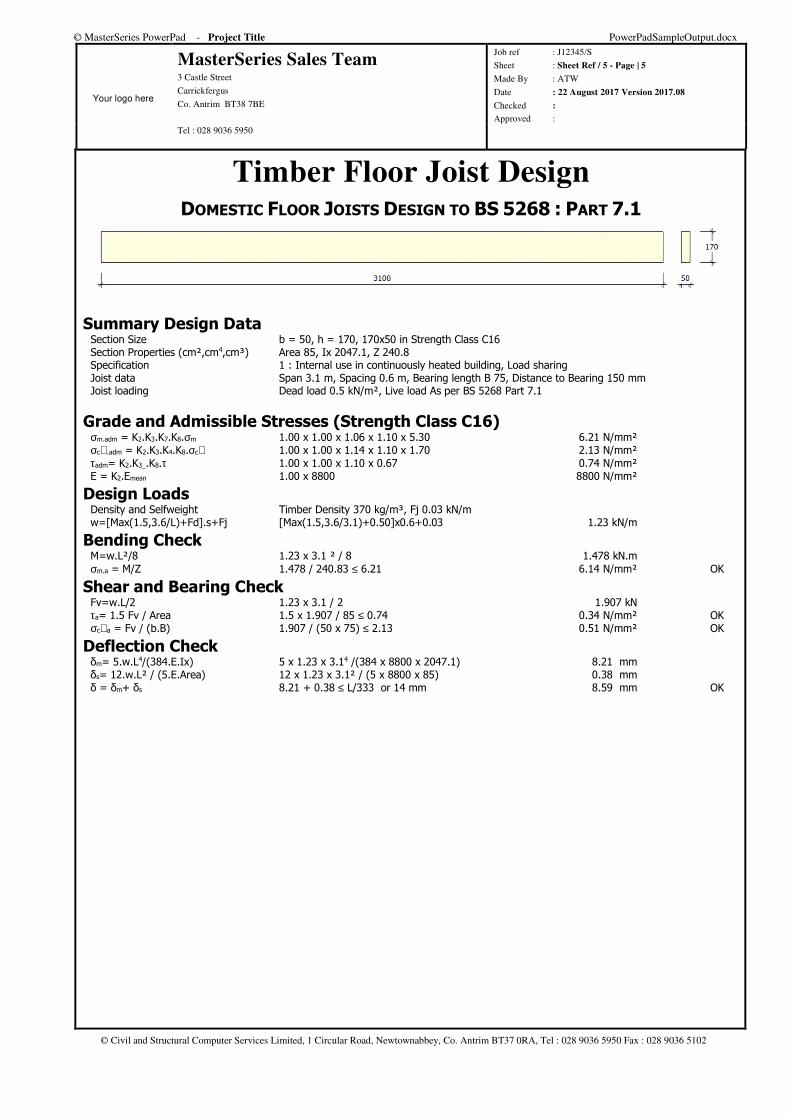
Timber Floor Joist Design DOMESTIC FLOOR JOISTS DESIGN TO BS 5268 : PART 7.1
Summary Design Data Section Size b = 50, h = 170, 170x50 in Strength Class C16 Section Properties (cm²,cm4,cm³) Area 85, Ix 2047.1, Z 240.8 Specification 1 : Internal use in continuously heated building, Load sharing Joist data Span 3.1 m, Spacing 0.6 m, Bearing length B 75, Distance to Bearing 150 mm Joist loading Dead load 0.5 kN/m², Live load As per BS 5268 Part 7.1
Grade and Admissible Stresses (Strength Class C16) σm.adm = K2.K3.K7.K8.σm 1.00 x 1.00 x 1.06 x 1.10 x 5.30 6.21 N/mm² σc⊥.adm = K2.K3.K4.K8.σc⊥ 1.00 x 1.00 x 1.14 x 1.10 x 1.70 2.13 N/mm² τadm= K2.K3_.K8.τ 1.00 x 1.00 x 1.10 x 0.67 0.74 N/mm² E = K2.Emean 1.00 x 8800 8800 N/mm²
Design Loads Density and Selfweight Timber Density 370 kg/m³, Fj 0.03 kN/m w=[Max(1.5,3.6/L)+Fd].s+Fj [Max(1.5,3.6/3.1)+0.50]x0.6+0.03 1.23 kN/m
Bending Check M=w.L²/8 1.23 x 3.1 ² / 8 1.478 kN.m σm.a = M/Z 1.478 / 240.83 ≤ 6.21 6.14 N/mm² OK
Shear and Bearing Check Fv=w.L/2 1.23 x 3.1 / 2 1.907 kN τa= 1.5 Fv / Area 1.5 x 1.907 / 85 ≤ 0.74 0.34 N/mm² OK σc⊥a = Fv / (b.B) 1.907 / (50 x 75) ≤ 2.13 0.51 N/mm² OK
Deflection Check δm= 5.w.L4/(384.E.Ix) 5 x 1.23 x 3.14 /(384 x 8800 x 2047.1) 8.21 mm δs= 12.w.L² / (5.E.Area) 12 x 1.23 x 3.1² / (5 x 8800 x 85) 0.38 mm δ = δm+ δs 8.21 + 0.38 ≤ L/333 or 14 mm 8.59 mm OK
© MasterSeries PowerPad - Project Title PowerPadSampleOutput.docx
Your logo here
MasterSeries Sales Team 3 Castle Street
Carrickfergus
Co. Antrim BT38 7BE
Job ref : J12345/S
Sheet : Sheet Ref / 6 - Page | 6
Made By : ATW
Date : 22 August 2017 Version 2017.08
Checked :
Approved : Tel : 028 9036 5950
© Civil and Structural Computer Services Limited, 1 Circular Road, Newtownabbey, Co. Antrim BT37 0RA, Tel : 028 9036 5950 Fax : 028 9036 5102
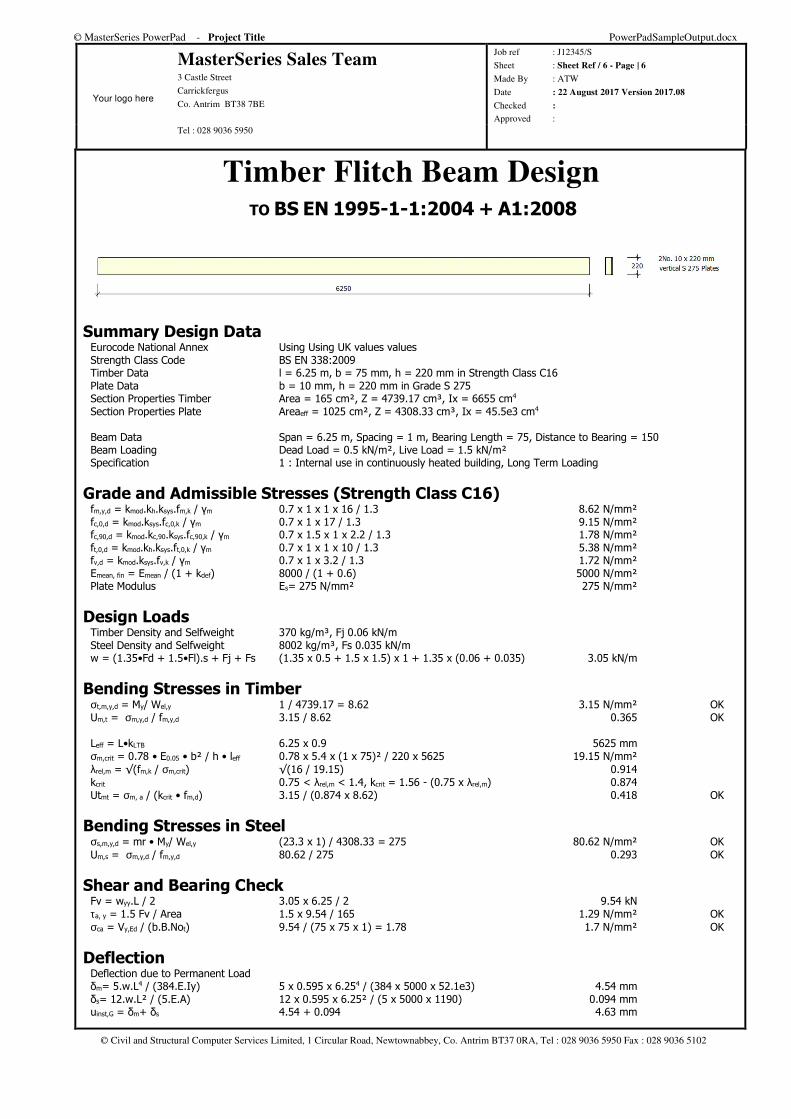
Timber Flitch Beam Design TO BS EN 1995-1-1:2004 + A1:2008
Summary Design Data Eurocode National Annex Using Using UK values values Strength Class Code BS EN 338:2009 Timber Data l = 6.25 m, b = 75 mm, h = 220 mm in Strength Class C16 Plate Data b = 10 mm, h = 220 mm in Grade S 275 Section Properties Timber Area = 165 cm², Z = 4739.17 cm³, Ix = 6655 cm4 Section Properties Plate Areaeff = 1025 cm², Z = 4308.33 cm³, Ix = 45.5e3 cm4 Beam Data Span = 6.25 m, Spacing = 1 m, Bearing Length = 75, Distance to Bearing = 150 Beam Loading Dead Load = 0.5 kN/m², Live Load = 1.5 kN/m² Specification 1 : Internal use in continuously heated building, Long Term Loading
Grade and Admissible Stresses (Strength Class C16) fm,y,d = kmod.kh.ksys.fm,k / γm 0.7 x 1 x 1 x 16 / 1.3 8.62 N/mm² fc,0,d = kmod.ksys.fc,0,k / γm 0.7 x 1 x 17 / 1.3 9.15 N/mm² fc,90,d = kmod.kc,90.ksys.fc,90,k / γm 0.7 x 1.5 x 1 x 2.2 / 1.3 1.78 N/mm² ft,0,d = kmod.kh.ksys.ft,0,k / γm 0.7 x 1 x 1 x 10 / 1.3 5.38 N/mm² fv,d = kmod.ksys.fv,k / γm 0.7 x 1 x 3.2 / 1.3 1.72 N/mm² Emean, fin = Emean / (1 + kdef) 8000 / (1 + 0.6) 5000 N/mm² Plate Modulus Es= 275 N/mm² 275 N/mm²
Design Loads Timber Density and Selfweight 370 kg/m³, Fj 0.06 kN/m Steel Density and Selfweight 8002 kg/m³, Fs 0.035 kN/m w = (1.35•Fd + 1.5•Fl).s + Fj + Fs (1.35 x 0.5 + 1.5 x 1.5) x 1 + 1.35 x (0.06 + 0.035) 3.05 kN/m
Bending Stresses in Timber σt,m,y,d = My/ Wel,y 1 / 4739.17 = 8.62 3.15 N/mm² OK Um,t = σm,y,d / fm,y,d 3.15 / 8.62 0.365 OK Leff = L•kLTB 6.25 x 0.9 5625 mm σm,crit = 0.78 • E0.05 • b² / h • leff 0.78 x 5.4 x (1 x 75)² / 220 x 5625 19.15 N/mm² λrel,m = √(fm,k / σm,crit) √(16 / 19.15) 0.914 kcrit 0.75 < λrel,m < 1.4, kcrit = 1.56 - (0.75 x λrel,m) 0.874 Utmt = σm, a / (kcrit • fm,d) 3.15 / (0.874 x 8.62) 0.418 OK
Bending Stresses in Steel σs,m,y,d = mr • My/ Wel,y (23.3 x 1) / 4308.33 = 275 80.62 N/mm² OK Um,s = σm,y,d / fm,y,d 80.62 / 275 0.293 OK
Shear and Bearing Check Fv = wyy.L / 2 3.05 x 6.25 / 2 9.54 kN τa, y = 1.5 Fv / Area 1.5 x 9.54 / 165 1.29 N/mm² OK σca = Vy,Ed / (b.B.Not) 9.54 / (75 x 75 x 1) = 1.78 1.7 N/mm² OK
Deflection Deflection due to Permanent Load δm= 5.w.L4 / (384.E.Iy) 5 x 0.595 x 6.254 / (384 x 5000 x 52.1e3) 4.54 mm δs= 12.w.L² / (5.E.A) 12 x 0.595 x 6.25² / (5 x 5000 x 1190) 0.094 mm uinst,G = δm+ δs 4.54 + 0.094 4.63 mm
© MasterSeries PowerPad - Project Title PowerPadSampleOutput.docx
Your logo here
MasterSeries Sales Team 3 Castle Street
Carrickfergus
Co. Antrim BT38 7BE
Job ref : J12345/S
Sheet : Sheet Ref / 7 - Page | 7
Made By : ATW
Date : 22 August 2017 Version 2017.08
Checked :
Approved : Tel : 028 9036 5950
© Civil and Structural Computer Services Limited, 1 Circular Road, Newtownabbey, Co. Antrim BT37 0RA, Tel : 028 9036 5950 Fax : 028 9036 5102
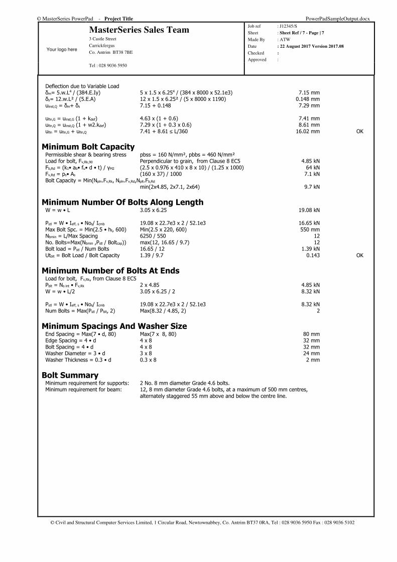
Deflection due to Variable Load δm= 5.w.L4 / (384.E.Iy) 5 x 1.5 x 6.254 / (384 x 8000 x 52.1e3) 7.15 mm δs= 12.w.L² / (5.E.A) 12 x 1.5 x 6.25² / (5 x 8000 x 1190) 0.148 mm uinst,Q = δm+ δs 7.15 + 0.148 7.29 mm ufin,G = uinst,G (1 + kdef) 4.63 x (1 + 0.6) 7.41 mm ufin,Q = uinst,Q (1 + w2.kdef) 7.29 x (1 + 0.3 x 0.6) 8.61 mm ufin = ufin,G + ufin,Q 7.41 + 8.61 ≤ L/360 16.02 mm OK
Minimum Bolt Capacity Permissible shear & bearing stress pbss = 160 N/mm², pbbs = 460 N/mm² Load for bolt, Fv,Rk,90 Perpendicular to grain, from Clause 8 EC5 4.85 kN Fb,Rd = (k1• ab• fu• d • t) / γM2 (2.5 x 0.976 x 410 x 8 x 10) / (1.25 x 1000) 64 kN Fv,Rd = ps• As (160 x 37) / 1000 7.1 kN Bolt Capacity = Min(Npln.Fv,Rk, Npln.Fv,Rd,Nplt.Fb,Rd min(2x4.85, 2x7.1, 2x64) 9.7 kN
Minimum Number Of Bolts Along Length W = w • L 3.05 x 6.25 19.08 kN Pstl = W • Ieff, s • Nos/ Icmb 19.08 x 22.7e3 x 2 / 52.1e3 16.65 kN Max Bolt Spc. = Min(2.5 • ht, 600) Min(2.5 x 220, 600) 550 mm Nbmin = L/Max Spacing 6250 / 550 12 No. Bolts=Max(Nbmin ,Pstl / Boltcap)) max(12, 16.65 / 9.7) 12 Bolt load = Pstl / Num Bolts 16.65 / 12 1.39 kN Utblt = Bolt Load / Bolt Capacity 1.39 / 9.7 0.143 OK
Minimum Number of Bolts At Ends Load for bolt, Fv,Rk, from Clause 8 EC5 Pblt = Ns int • Fv,Rk 2 x 4.85 4.85 kN W = w • L/2 3.05 x 6.25 / 2 8.32 kN Pstl = W • Ieff, s • Nos/ Icmb 19.08 x 22.7e3 x 2 / 52.1e3 8.32 kN Num Bolts = Max(Pstl / Pblt, 2) Max(8.32 / 4.85, 2) 2
Minimum Spacings And Washer Size End Spacing = Max(7 • d, 80) Max(7 x 8, 80) 80 mm Edge Spacing = 4 • d 4 x 8 32 mm Bolt Spacing = 4 • d 4 x 8 32 mm Washer Diameter = 3 • d 3 x 8 24 mm Washer Thickness = 0.3 • d 0.3 x 8 2 mm
Bolt Summary Minimum requirement for supports: 2 No. 8 mm diameter Grade 4.6 bolts. Minimum requirement for beam: 12, 8 mm diameter Grade 4.6 bolts, at a maximum of 500 mm centres, alternately staggered 55 mm above and below the centre line.
© MasterSeries PowerPad - Project Title PowerPadSampleOutput.docx
Your logo here
MasterSeries Sales Team 3 Castle Street
Carrickfergus
Co. Antrim BT38 7BE
Job ref : J12345/S
Sheet : Sheet Ref / 8 - Page | 8
Made By : ATW
Date : 22 August 2017 Version 2017.08
Checked :
Approved : Tel : 028 9036 5950
© Civil and Structural Computer Services Limited, 1 Circular Road, Newtownabbey, Co. Antrim BT37 0RA, Tel : 028 9036 5950 Fax : 028 9036 5102
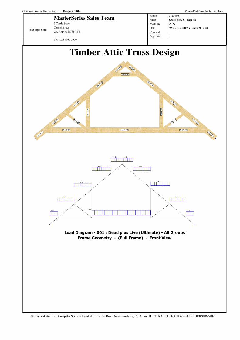
Timber Attic Truss Design
Load Diagram - 001 : Dead plus Live (Ultimate) - All Groups
Frame Geometry - (Full Frame) - Front View
© MasterSeries PowerPad - Project Title PowerPadSampleOutput.docx
Your logo here
MasterSeries Sales Team 3 Castle Street
Carrickfergus
Co. Antrim BT38 7BE
Job ref : J12345/S
Sheet : Sheet Ref / 9 - Page | 9
Made By : ATW
Date : 22 August 2017 Version 2017.08
Checked :
Approved : Tel : 028 9036 5950
© Civil and Structural Computer Services Limited, 1 Circular Road, Newtownabbey, Co. Antrim BT37 0RA, Tel : 028 9036 5950 Fax : 028 9036 5102
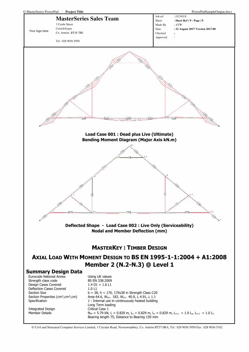
Load Case 001 : Dead plus Live (Ultimate)
Bending Moment Diagram (Major Axis kN.m)
Deflected Shape - Load Case 002 : Live Only (Serviceability)
Nodal and Member Deflection (mm)
MASTERKEY : TIMBER DESIGN
AXIAL LOAD WITH MOMENT DESIGN TO BS EN 1995-1-1:2004 + A1:2008
Member 2 (N.2-N.3) @ Level 1 Summary Design Data Eurocode National Annex Using UK values Strength class code BS EN 338:2009 Design Cases Covered 1.4 D1 + 1.6 L1 Deflection Cases Covered 1.0 L1 Section Size b = 38, h = 170, 170x38 in Strength Class C20 Section Properties (cm²,cm³,cm) Area 64.6, Wel.y 183, Wel.z 40.9, iy 4.91, iz 1.1 Specification 1 : Internal use in continuously heated building Long Term loading Integrated Design Critical Case 1 Member Details NEd = 5.79 kN, L = 0.829 m, Ly = 0.829 m, Lz = 0.829 m, Lcr.y = 1.0 Ly, Lcr.z = 1.0 Lz Bearing length 75, Distance to Bearing 150 mm
© MasterSeries PowerPad - Project Title PowerPadSampleOutput.docx
Your logo here
MasterSeries Sales Team 3 Castle Street
Carrickfergus
Co. Antrim BT38 7BE
Job ref : J12345/S
Sheet : Sheet Ref / 10 - Page | 10
Made By : ATW
Date : 22 August 2017 Version 2017.08
Checked :
Approved : Tel : 028 9036 5950
© Civil and Structural Computer Services Limited, 1 Circular Road, Newtownabbey, Co. Antrim BT37 0RA, Tel : 028 9036 5950 Fax : 028 9036 5102
Grade and Admissible Stresses (Strength Class C20) fm.y.d = Kmod.Khy.Ksys.fm.k/γm 0.70 x 1.00 x 1.00 x 20.00/1.3 10.77 N/mm² fm.z.d = Kmod.Khz.Ksys.fm.k/γm 0.70 x 1.30 x 1.00 x 20.00/1.3 14.00 N/mm² fc.0.d = Kmod.Ksys.fc.0.k/γm 0.70 x 1.00 x 19.00/1.3 10.23 N/mm² fc.90.d = Kmod.Kc.90.Ksys.fc.90.k/γm 0.70 x 1.50 x 1.00 x 2.30/1.3 1.86 N/mm² fv.d = Kmod.Ksys.fv.k/γm 0.70 x 1.00 x 3.60/1.3 1.94 N/mm² Emean Instantaneous Deflection 9500 N/mm² Deflection
Compression Resistance λy= Ley/iy 83/4.907 ≤ 180 16.9 OK λrel.y= λy/π √ (fc.0.k/E0.05) 16.9/π √ 19/6400 0.293 kc.y = fn( βc, λrel.y, ky) 0.2, 0.293, 0.542 1.002 fc.y.0.d = kc.y . fc.0.d 1.002 x 10.23 10.25 N/mm² λz= Lez/iz 83/1.097 ≤ 180 75.6 OK λrel.z= λz/π √ (fc.0.k/E0.05) 75.6/π √ 19/6400 1.311 kc.z = fn( βc, λrel.z, kz) 0.2, 1.311, 1.460 0.475 fc.z.0.d = kc.z . fc.0.d 0.475 x 10.23 4.86 N/mm² σc.a = NEd/Area 5.79 / 64.6 ≤ 4.86 0.90 N/mm² OK
Axial Load with Moments Check Critical Design Location X = 0.000 σm.y.d = My/Wel.y 0.841 / 183.03 ≤ 10.77 4.59 N/mm² OK Uc.y = σc.0.d/(kc.y•fc.0.d) 0.896/(1.002x10.231) 0.087 OK Uc.z = σc.0.d/(kc.z•fc.0.d) 0.896/(0.475x10.231) 0.184 OK Um.y = σm.y.d/fm.y.d 4.590/10.769 0.426 OK Uc.z+Um.y 0.184+0.426 0.610 OK kCrit Full restrained on compression side 1.0
Shear and Bearing Check Critical Design Location X = 0.818 τa= 1.5 Vy.Ed / Area / kcr 1.5 x 1.469 / 64.6 / 0.67 ≤ 1.94 0.51 N/mm² OK σc⊥ax = Vy.Ed / (b.ly) 1.469 / (38 x 75) ≤ 1.86 0.52 N/mm² OK
Deflection Check (Shear Deflection NOT Included) Critical Load Case 002 : Live Only (Serviceability) δ = δm In-span 0.06 ≤ L/250 0.06 mm OK
MASTERKEY : TIMBER DESIGN
AXIAL LOAD WITH MOMENT DESIGN TO BS EN 1995-1-1:2004 + A1:2008
Member 12 (N.6-N.8) @ Level 1 Summary Design Data Eurocode National Annex Using UK values Strength class code BS EN 338:2009 Design Cases Covered 1.4 D1 + 1.6 L1 Deflection Cases Covered 1.0 L1 Section Size b = 38, h = 170, 170x38 in Strength Class C20 Section Properties (cm²,cm³,cm) Area 64.6, Wel.y 183, Wel.z 40.9, iy 4.91, iz 1.1 Specification 1 : Internal use in continuously heated building Long Term loading, One piece Integrated Design Critical Case 1 Member Details NEd = -2.953 kN, L = 2.271 m, Ly = 2.271 m, Lz = 2.271 m, Lcr.y = 1.0 Ly, Lcr.z = 1.0 Lz Bearing length 75, Distance to Bearing 150 mm
Grade and Admissible Stresses (Strength Class C20) fm.y.d = Kmod.Khy.Ksys.fm.k/γm 0.70 x 1.00 x 1.10 x 20.00/1.3 11.85 N/mm² fm.z.d = Kmod.Khz.Ksys.fm.k/γm 0.70 x 1.30 x 1.10 x 20.00/1.3 15.40 N/mm² ft.0.d = Kmod.Kh.Ksys.ft.0.k/γm 0.70 x 1.00 x 1.10 x 12.00/1.3 7.11 N/mm² fc.90.d = Kmod.Kc.90.Ksys.fc.90.k/γm 0.70 x 1.50 x 1.10 x 2.30/1.3 2.04 N/mm² fv.d = Kmod.Ksys.fv.k/γm 0.70 x 1.10 x 3.60/1.3 2.13 N/mm² Emean Instantaneous Deflection 9500 N/mm² Deflection
Tensile Resistance σt.a = NEd/Area 2.953 / 64.6 ≤ 7.11 0.46 N/mm² OK
© MasterSeries PowerPad - Project Title PowerPadSampleOutput.docx
Your logo here
MasterSeries Sales Team 3 Castle Street
Carrickfergus
Co. Antrim BT38 7BE
Job ref : J12345/S
Sheet : Sheet Ref / 11 - Page | 11
Made By : ATW
Date : 22 August 2017 Version 2017.08
Checked :
Approved : Tel : 028 9036 5950
© Civil and Structural Computer Services Limited, 1 Circular Road, Newtownabbey, Co. Antrim BT37 0RA, Tel : 028 9036 5950 Fax : 028 9036 5102
Axial Load with Moments Check Critical Design Location X = 1.136 σm.y.d = My/Wel.y 0.428 / 183.03 ≤ 11.85 2.34 N/mm² OK Ut= σc.0.d/ft.0.d 0.457/7.108 0.064 OK Um.y = σm.y.d/fm.y.d 2.340/11.846 0.198 OK Ut+Um.y 0.064+0.198 0.262 OK
Shear and Bearing Check Critical Design Location X = 0.000 τa= 1.5 Vy.Ed / Area / kcr 1.5 x 1.044 / 64.6 / 0.67 ≤ 2.13 0.36 N/mm² OK σc⊥ax = Vy.Ed / (b.ly) 1.044 / (38 x 75) ≤ 2.04 0.37 N/mm² OK
Deflection Check (Shear Deflection NOT Included) Critical Load Case 002 : Live Only (Serviceability) δ = δm In-span 0.63 ≤ L/250 0.63 mm OK
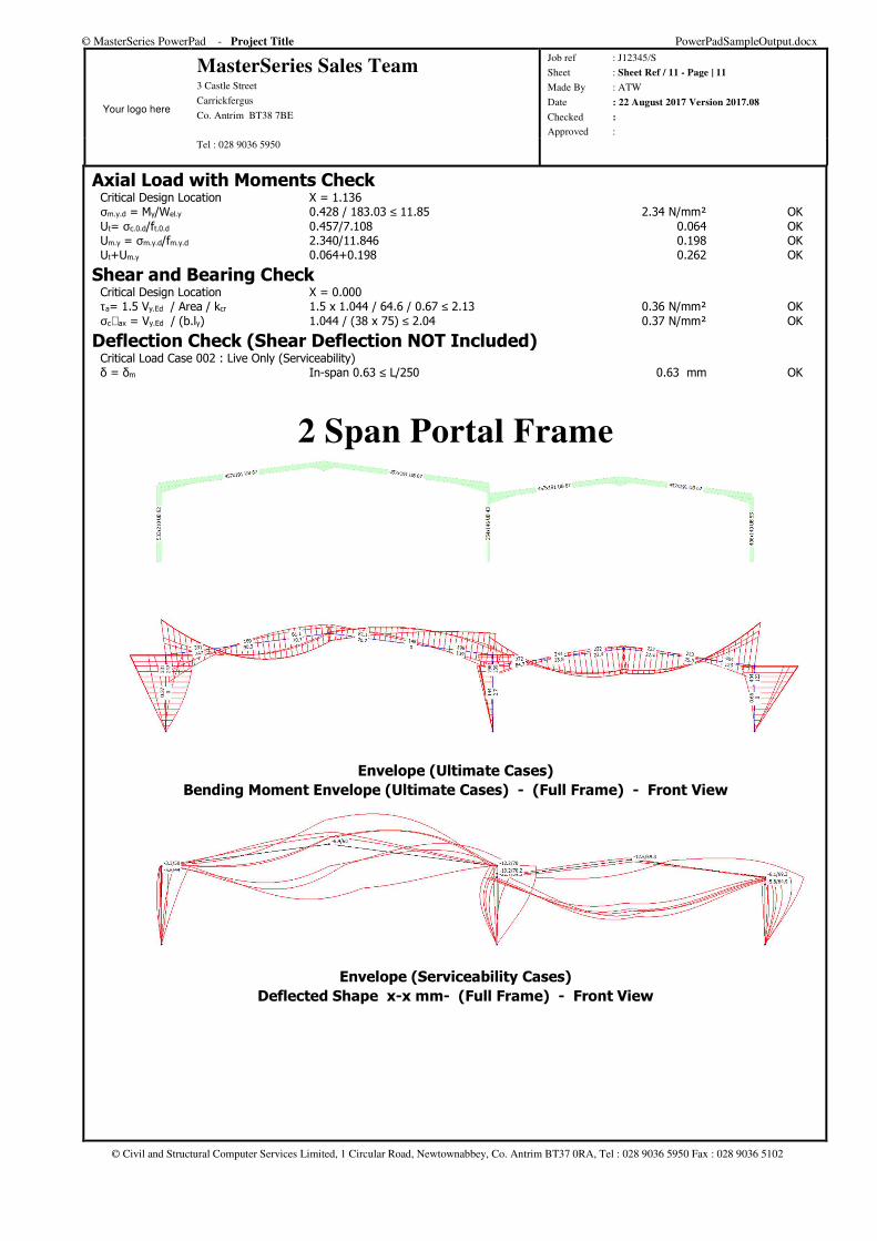
2 Span Portal Frame
Envelope (Ultimate Cases)
Bending Moment Envelope (Ultimate Cases) - (Full Frame) - Front View
Envelope (Serviceability Cases)
Deflected Shape x-x mm- (Full Frame) - Front View
© MasterSeries PowerPad - Project Title PowerPadSampleOutput.docx
Your logo here
MasterSeries Sales Team 3 Castle Street
Carrickfergus
Co. Antrim BT38 7BE
Job ref : J12345/S
Sheet : Sheet Ref / 12 - Page | 12
Made By : ATW
Date : 22 August 2017 Version 2017.08
Checked :
Approved : Tel : 028 9036 5950
© Civil and Structural Computer Services Limited, 1 Circular Road, Newtownabbey, Co. Antrim BT37 0RA, Tel : 028 9036 5950 Fax : 028 9036 5102
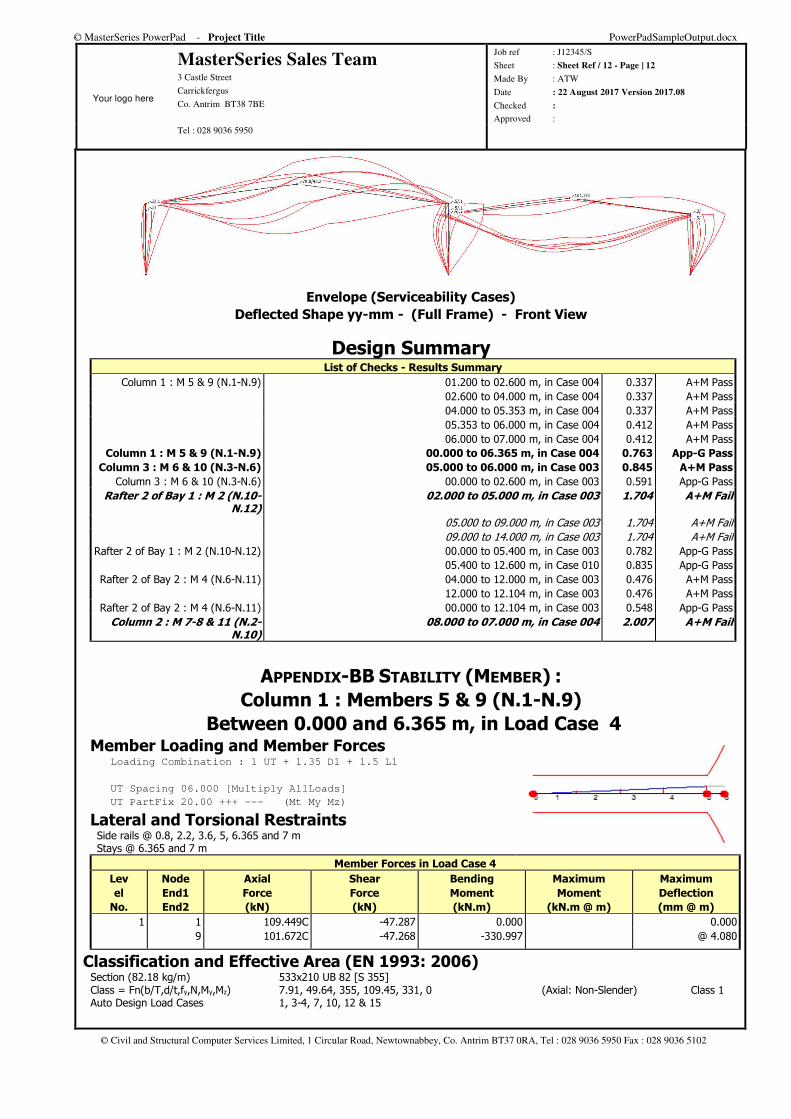
Envelope (Serviceability Cases)
Deflected Shape yy-mm - (Full Frame) - Front View
Design Summary List of Checks - Results Summary
Column 1 : M 5 & 9 (N.1-N.9) 01.200 to 02.600 m, in Case 004 0.337 A+M Pass 02.600 to 04.000 m, in Case 004 0.337 A+M Pass 04.000 to 05.353 m, in Case 004 0.337 A+M Pass 05.353 to 06.000 m, in Case 004 0.412 A+M Pass 06.000 to 07.000 m, in Case 004 0.412 A+M Pass
Column 1 : M 5 & 9 (N.1-N.9) 00.000 to 06.365 m, in Case 004 0.763 App-G Pass
Column 3 : M 6 & 10 (N.3-N.6) 05.000 to 06.000 m, in Case 003 0.845 A+M Pass
Column 3 : M 6 & 10 (N.3-N.6) 00.000 to 02.600 m, in Case 003 0.591 App-G Pass Rafter 2 of Bay 1 : M 2 (N.10-
N.12) 02.000 to 05.000 m, in Case 003 1.704 A+M Fail
05.000 to 09.000 m, in Case 003 1.704 A+M Fail 09.000 to 14.000 m, in Case 003 1.704 A+M Fail
Rafter 2 of Bay 1 : M 2 (N.10-N.12) 00.000 to 05.400 m, in Case 003 0.782 App-G Pass 05.400 to 12.600 m, in Case 010 0.835 App-G Pass
Rafter 2 of Bay 2 : M 4 (N.6-N.11) 04.000 to 12.000 m, in Case 003 0.476 A+M Pass 12.000 to 12.104 m, in Case 003 0.476 A+M Pass
Rafter 2 of Bay 2 : M 4 (N.6-N.11) 00.000 to 12.104 m, in Case 003 0.548 App-G Pass Column 2 : M 7-8 & 11 (N.2-
N.10) 08.000 to 07.000 m, in Case 004 2.007 A+M Fail
APPENDIX-BB STABILITY (MEMBER) :
Column 1 : Members 5 & 9 (N.1-N.9)
Between 0.000 and 6.365 m, in Load Case 4 Member Loading and Member Forces Loading Combination : 1 UT + 1.35 D1 + 1.5 L1
UT Spacing 06.000 [Multiply AllLoads]
UT PartFix 20.00 +++ --- (Mt My Mz)
Lateral and Torsional Restraints Side rails @ 0.8, 2.2, 3.6, 5, 6.365 and 7 m Stays @ 6.365 and 7 m
Member Forces in Load Case 4
Lev
el
No.
Node
End1
End2
Axial
Force
(kN)
Shear
Force
(kN)
Bending
Moment
(kN.m)
Maximum
Moment
(kN.m @ m)
Maximum
Deflection
(mm @ m)
1 1 109.449C -47.287 0.000 0.000
9 101.672C -47.268 -330.997 @ 4.080
Classification and Effective Area (EN 1993: 2006) Section (82.18 kg/m) 533x210 UB 82 [S 355] Class = Fn(b/T,d/t,fy,N,My,Mz) 7.91, 49.64, 355, 109.45, 331, 0 (Axial: Non-Slender) Class 1 Auto Design Load Cases 1, 3-4, 7, 10, 12 & 15
© MasterSeries PowerPad - Project Title PowerPadSampleOutput.docx
Your logo here
MasterSeries Sales Team 3 Castle Street
Carrickfergus
Co. Antrim BT38 7BE
Job ref : J12345/S
Sheet : Sheet Ref / 13 - Page | 13
Made By : ATW
Date : 22 August 2017 Version 2017.08
Checked :
Approved : Tel : 028 9036 5950
© Civil and Structural Computer Services Limited, 1 Circular Road, Newtownabbey, Co. Antrim BT37 0RA, Tel : 028 9036 5950 Fax : 028 9036 5102
Tension Side Lateral Restraint Spacing Check, Lm Lm= fn(NEd, A, C1, Wpl,y, IT) 109.4, 104.7,1.11, 2058.6, 51.5 1.149m Lm< s 1.149<1.400 - Effect of tension side lateral restraints ignored
Compression Resistance N.b.Rd λz = √A.fy/Ncrz √104.69x355/1030.45 1.898 Nb.z.Rd = Area.χ.fy/ γM1 104.69x0.23x355/10/1 = 854.355 kN Curve b is= Fn(iy, iz, a) 213.1, 43.9, 317.0 217.6 mm NcrT= Fn(E, Iz, It, Iw, Lt, a, is) 210, 2014, 52, 1.328, 6365, 0, 218 2314.6 kN λT = √A.fy/NcrT √104.69x355/ 10 /2314.63 1.267 Nb.T.Rd= Area.χ.fy/ γM1 104.69x0.443x355/10/1 = 1646.575 kN Curve b
Lateral Buckling Resistance Moment Mb Mcr0 = fn(Lt, E, Iz, IT, Iw) 6.365, 210, 2014, 51.52, 1.328 336.018 kN.m Mcr = C1• Mcr0 1.750 • 336.0 587.976 kN.m λLT= √ W.fy/Mcr √ 2058.6 x 355 / 123.2 1.115 χLT= Fn(λLT, φLT, β) 1.115, 1.141, 0.750 0.572 Curve c χLT.mod = Fn(χLT,λLT,kc,f) 0.572, 1.115, 0.756, 0.902 0.633 6.3.2.3 Mb.Rd = χ Wpl.y.fy 0.633 x 2059 x 355 462.963 kN.m
Combined Axial and Bending 6.62 kzy 1- {0.1λT/(CmLT-0.25)}• NEd/Nb,z,Rd 0.976 NEd/Nb,z,Rd+kzy.My,Ed/Mb,Rd 109.449 / 854.355 + 0.976 x 300.982 / 462.963 = 0.763 OK
AXIAL WITH MOMENTS (MEMBER)
Column 3 : Members 6 & 10 (N.3-N.6)
Between 1.200 and 2.600 m, in Load Case 3 Member Loading and Member Forces Loading Combination : 1 UT + 1.35 D1 + 1.5 L1
UT Spacing 06.000 [Multiply AllLoads]
UT PartFix 20.00 +++ --- (Mt My Mz)
Member Forces in Load Case 3 and Maximum Deflection from Load Case 9
Lev
el
No.
Node
End1
End2
Axial
Force
(kN)
Shear
Force
(kN)
Bending
Moment
(kN.m)
Maximum
Moment
(kN.m @ m)
Maximum
Deflection
(mm @ m)
1 3 120.267C -67.343 0.000 14.079
6 115.927C -67.332 -404.051 @ 3.587
Classification and Effective Area (EN 1993: 2006) Section (53.33 kg/m) 406x140 UB 53 [S 355] Class = Fn(b/T,d/t,fy,N,My,Mz) 5.55, 45.62, 355, 120.27, 404.05, 0 (Axial: Non-Slender) Class 1 Auto Design Load Cases 1, 3-4, 7, 10, 12 & 15
Local Capacity Check Vy.Ed/Vpl.y.Rd 67.343 / 709.555 = 0.095 Low Shear Mc.y.Rd = fy.Wpl.y/ γM0 355 x 1031/1 366.005 kN.m Npl.Rd = Ag.fy/ γM0 67.94 x 355/1 = 2411.87 kN n = NEd/Npl.Rd 115.927 / 2411.87 = 0.048 OK Wpl.N.y = Fn(Wpl.y, Avy, n) 1031, 34.619, 0.048 1031 cm³ MN.y.Rd = Wpl.N.y.fy/ γM0 1031 x 355/1 366.005 kN.m (My.Ed/MN.y.Rd)+(Mz.Ed/MN.z.Rd) (175.095/366.005)²+(0)1= 0.229 OK
Compression Resistance N.b.Rd λy = √A.fy/Ncr √67.94x355/10525.96 0.479 Nb.y.Rd = Area.χ.fy/ γM1 67.94x0.931x355/10/1 = 2244.786 kN Curve a λz = √A.fy/Ncrz √67.94x355/6710.63 0.599 Nb.z.Rd = Area.χ.fy/ γM1 67.94x0.838x355/10/1 = 2020.363 kN Curve b Let = Kt.Lx 1x6 = 6 λT = √A.fy/NcrT √67.94x355/1347.43 1.338 Nb.T.Rd= Area.χ.fy/ γM1 67.94x0.409x355/10/1 = 986.586 kN Curve b
© MasterSeries PowerPad - Project Title PowerPadSampleOutput.docx
Your logo here
MasterSeries Sales Team 3 Castle Street
Carrickfergus
Co. Antrim BT38 7BE
Job ref : J12345/S
Sheet : Sheet Ref / 14 - Page | 14
Made By : ATW
Date : 22 August 2017 Version 2017.08
Checked :
Approved : Tel : 028 9036 5950
© Civil and Structural Computer Services Limited, 1 Circular Road, Newtownabbey, Co. Antrim BT37 0RA, Tel : 028 9036 5950 Fax : 028 9036 5102
Equivalent Uniform Moment Factor C1 C1= fn(M1, M2, ψ) -80.9, -175.0, 0.462 1.329 Not Loaded CmLT=Max(0.6+0.4ψ, 0.4) M = -175.03, ψ = 0.462 0.785 Table B.3 Cmz=Max(0.6+0.4ψ, 0.4) M = 0, ψ = 1.000 1 Table B.3 Cmy=Max(0.6+0.4ψ, 0.4) M = -404.05, ψ = 0.000 0.6 Table B.3
Lateral Buckling Check M.b.Rd Le = 1.00 L 1 x 1.4 = 1.4 m Mcr= Fn(C1,Le,Iz,It,Iw,E) 1.329, 1.400, 634.6, 28.96, 0.2452, 210000 1830.086 kN.m λLT= √ W.fy/Mcr √ 1031 x 355 / 1830.086 0.447 χLT= Fn(λLT, λLT5950 ) 0.447, 0.510 0.974 Curve c χLT.mod = Fn(χLT,λLT,kc,f) 0.974, 0.447, 0.867, 0.950 1.000 6.3.2.3 Mb.Rd = χ Wpl.y.fy≤ Mc.y.Rd 1.000 x 1031 x 355 ≤ 366.005 = 366.005 kN.m
Buckling Resistance UN.y = NEd/(χy.NRk/γM1) 120.267 / 2244.786 0.054 OK UN.z = NEd/(χz.NRk/γM1) 120.267 / 2020.363 0.060 OK UM.y = My.Ed/(χLT.My.Rk/γM1) 175.095 / 366.005 0.478 OK UM.z = Mz.Ed/(Mz.Rk/γM1) 0 / 49.31 0.000 OK kyy=Cmy{1+(λy-0.2)UN.y} 0.609 kzz=Cmz{1+(2λz-0.6)UN.z} 1.036 kyz=0.6 kzz 0.621 kzy=0.6 kyy 0.365 UNy+kyy.UM.y+kyz.UM.z 0.054+0.609x0.478+0.621x0.000 0.345 OK UNz+kzy.UM.y+kzz.UM.z 0.060+0.365x0.478+1.036x0.000 0.234 OK
Deflection Check - Load Case 9 In-span δ ≤ Span/360 14.08 ≤ 6000 / 360 14.08 mm OK
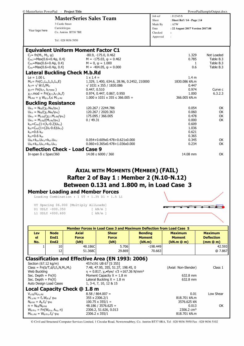
AXIAL WITH MOMENTS (MEMBER) (FAIL)
Rafter 2 of Bay 1 : Member 2 (N.10-N.12)
Between 0.131 and 1.800 m, in Load Case 3 Member Loading and Member Forces Loading Combination : 1 UT + 1.35 D1 + 1.5 L1
UT Spacing 06.000 [Multiply AllLoads]
D1 UDLY -000.350 [ kN/m ]
L1 UDLY +000.600 [ kN/m ]
Member Forces in Load Case 3 and Maximum Deflection from Load Case 5
Lev
el
No.
Node
End1
End2
Axial
Force
(kN)
Shear
Force
(kN)
Bending
Moment
(kN.m)
Maximum
Moment
(kN.m @ m)
Maximum
Deflection
(mm @ m)
1 10 48.186C 5.706 -198.449 42.593
12 51.368C 29.869 70.663 @ 7.867
Classification and Effective Area (EN 1993: 2006) Section (67.12 kg/m) 457x191 UB 67 [S 355] Class = Fn(b/T,d/t,fy,N,My,Mz) 7.48, 47.95, 355, 51.37, 198.45, 0 (Axial: Non-Slender) Class 1 Web Buckling η = 0.817, χw•fyw/ √3 =167.36 N/mm² Sec. Depth = Fn(X) Moment Capacity X = 1.8 m 632.8 mm Sec. Depth = Fn(X) Lateral Buckling X = 1.8 m 632.8 mm Auto Design Load Cases 1, 3-4, 7, 10, 12 & 15
Local Capacity Check @ 1.8 m Vy.Ed/Vpl.y.Rd 8.58 / 864.007 = 0.01 Low Shear Mc.y.Rd = fy.Wpl.y/ γM0 355 x 2306.2/1 818.701 kN.m Npl.Rd = Ag.fy/ γM0 100.75 x 355/1 = 3576.625 kN n = NEd/Npl.Rd 48.186 / 3576.625 = 0.013 OK Wpl.N.y = Fn(Wpl.y, Avy, n) 2306.2, 51.626, 0.013 2306.2 cm³ MN.y.Rd = Wpl.N.y.fy/ γM0 2306.2 x 355/1 818.701 kN.m
© MasterSeries PowerPad - Project Title PowerPadSampleOutput.docx
Your logo here
MasterSeries Sales Team 3 Castle Street
Carrickfergus
Co. Antrim BT38 7BE
Job ref : J12345/S
Sheet : Sheet Ref / 15 - Page | 15
Made By : ATW
Date : 22 August 2017 Version 2017.08
Checked :
Approved : Tel : 028 9036 5950
© Civil and Structural Computer Services Limited, 1 Circular Road, Newtownabbey, Co. Antrim BT37 0RA, Tel : 028 9036 5950 Fax : 028 9036 5102
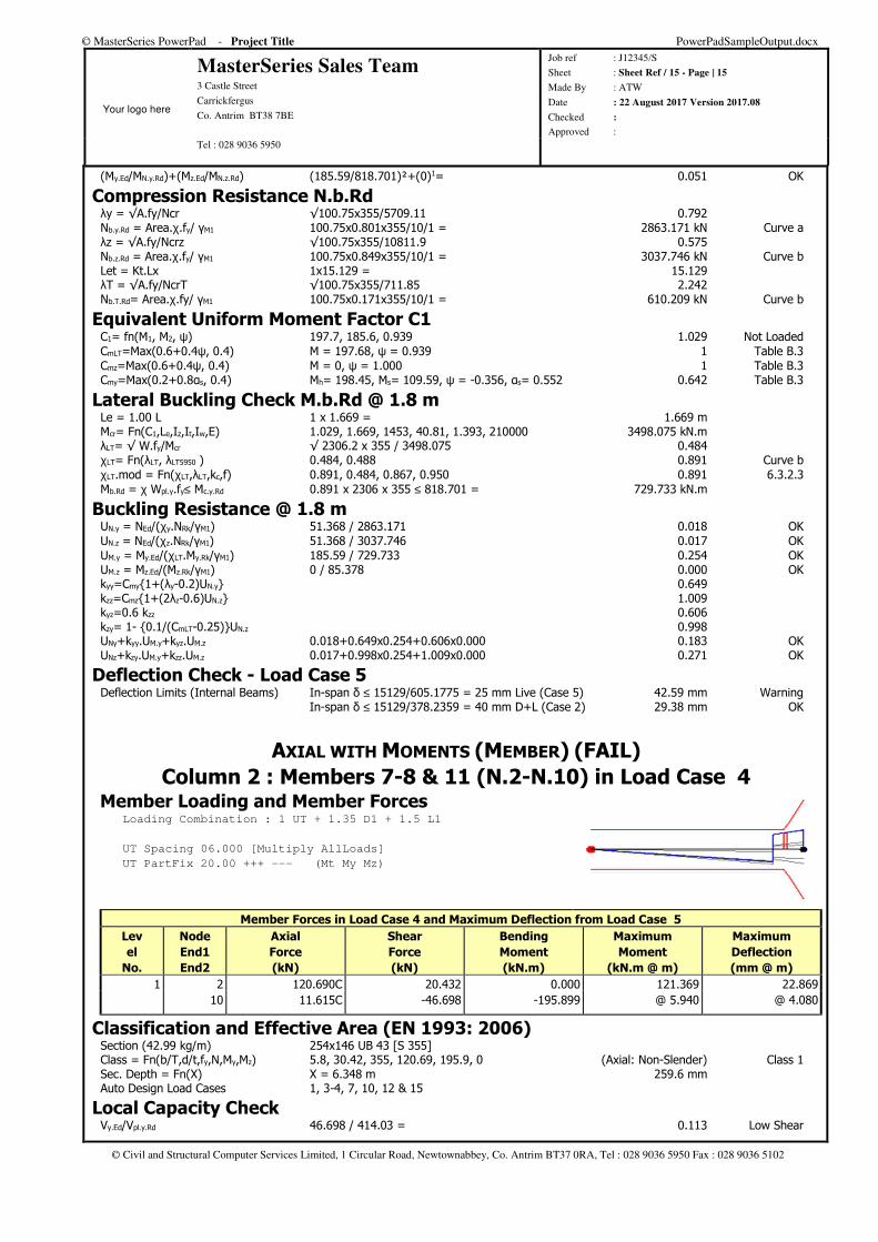
(My.Ed/MN.y.Rd)+(Mz.Ed/MN.z.Rd) (185.59/818.701)²+(0)1= 0.051 OK
Compression Resistance N.b.Rd λy = √A.fy/Ncr √100.75x355/5709.11 0.792 Nb.y.Rd = Area.χ.fy/ γM1 100.75x0.801x355/10/1 = 2863.171 kN Curve a λz = √A.fy/Ncrz √100.75x355/10811.9 0.575 Nb.z.Rd = Area.χ.fy/ γM1 100.75x0.849x355/10/1 = 3037.746 kN Curve b Let = Kt.Lx 1x15.129 = 15.129 λT = √A.fy/NcrT √100.75x355/711.85 2.242 Nb.T.Rd= Area.χ.fy/ γM1 100.75x0.171x355/10/1 = 610.209 kN Curve b
Equivalent Uniform Moment Factor C1 C1= fn(M1, M2, ψ) 197.7, 185.6, 0.939 1.029 Not Loaded CmLT=Max(0.6+0.4ψ, 0.4) M = 197.68, ψ = 0.939 1 Table B.3 Cmz=Max(0.6+0.4ψ, 0.4) M = 0, ψ = 1.000 1 Table B.3 Cmy=Max(0.2+0.8αs, 0.4) Mh= 198.45, Ms= 109.59, ψ = -0.356, αs= 0.552 0.642 Table B.3
Lateral Buckling Check M.b.Rd @ 1.8 m Le = 1.00 L 1 x 1.669 = 1.669 m Mcr= Fn(C1,Le,Iz,It,Iw,E) 1.029, 1.669, 1453, 40.81, 1.393, 210000 3498.075 kN.m λLT= √ W.fy/Mcr √ 2306.2 x 355 / 3498.075 0.484 χLT= Fn(λLT, λLT5950 ) 0.484, 0.488 0.891 Curve b χLT.mod = Fn(χLT,λLT,kc,f) 0.891, 0.484, 0.867, 0.950 0.891 6.3.2.3 Mb.Rd = χ Wpl.y.fy≤ Mc.y.Rd 0.891 x 2306 x 355 ≤ 818.701 = 729.733 kN.m
Buckling Resistance @ 1.8 m UN.y = NEd/(χy.NRk/γM1) 51.368 / 2863.171 0.018 OK UN.z = NEd/(χz.NRk/γM1) 51.368 / 3037.746 0.017 OK UM.y = My.Ed/(χLT.My.Rk/γM1) 185.59 / 729.733 0.254 OK UM.z = Mz.Ed/(Mz.Rk/γM1) 0 / 85.378 0.000 OK kyy=Cmy{1+(λy-0.2)UN.y} 0.649 kzz=Cmz{1+(2λz-0.6)UN.z} 1.009 kyz=0.6 kzz 0.606 kzy= 1- {0.1/(CmLT-0.25)}UN.z 0.998 UNy+kyy.UM.y+kyz.UM.z 0.018+0.649x0.254+0.606x0.000 0.183 OK UNz+kzy.UM.y+kzz.UM.z 0.017+0.998x0.254+1.009x0.000 0.271 OK
Deflection Check - Load Case 5 Deflection Limits (Internal Beams) In-span δ ≤ 15129/605.1775 = 25 mm Live (Case 5) 42.59 mm Warning In-span δ ≤ 15129/378.2359 = 40 mm D+L (Case 2) 29.38 mm OK
AXIAL WITH MOMENTS (MEMBER) (FAIL)
Column 2 : Members 7-8 & 11 (N.2-N.10) in Load Case 4 Member Loading and Member Forces Loading Combination : 1 UT + 1.35 D1 + 1.5 L1
UT Spacing 06.000 [Multiply AllLoads]
UT PartFix 20.00 +++ --- (Mt My Mz)
Member Forces in Load Case 4 and Maximum Deflection from Load Case 5
Lev
el
No.
Node
End1
End2
Axial
Force
(kN)
Shear
Force
(kN)
Bending
Moment
(kN.m)
Maximum
Moment
(kN.m @ m)
Maximum
Deflection
(mm @ m)
1 2 120.690C 20.432 0.000 121.369 22.869
10 11.615C -46.698 -195.899 @ 5.940 @ 4.080
Classification and Effective Area (EN 1993: 2006) Section (42.99 kg/m) 254x146 UB 43 [S 355] Class = Fn(b/T,d/t,fy,N,My,Mz) 5.8, 30.42, 355, 120.69, 195.9, 0 (Axial: Non-Slender) Class 1 Sec. Depth = Fn(X) X = 6.348 m 259.6 mm Auto Design Load Cases 1, 3-4, 7, 10, 12 & 15
Local Capacity Check Vy.Ed/Vpl.y.Rd 46.698 / 414.03 = 0.113 Low Shear
© MasterSeries PowerPad - Project Title PowerPadSampleOutput.docx
Your logo here
MasterSeries Sales Team 3 Castle Street
Carrickfergus
Co. Antrim BT38 7BE
Job ref : J12345/S
Sheet : Sheet Ref / 16 - Page | 16
Made By : ATW
Date : 22 August 2017 Version 2017.08
Checked :
Approved : Tel : 028 9036 5950
© Civil and Structural Computer Services Limited, 1 Circular Road, Newtownabbey, Co. Antrim BT37 0RA, Tel : 028 9036 5950 Fax : 028 9036 5102
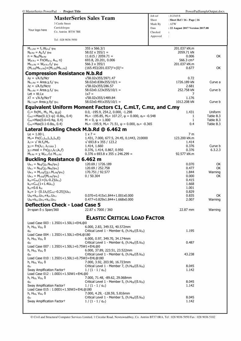
Mc.y.Rd = fy.Wpl.y/ γM0 355 x 566.3/1 201.037 kN.m Npl.Rd = Ag.fy/ γM0 58.02 x 355/1 = 2059.71 kN n = NEd/Npl.Rd 11.615 / 2059.71 = 0.006 OK Wpl.N.y = Fn(Wpl.y, Avy, n) 693.8, 20.201, 0.006 566.3 cm³ MN.y.Rd = Wpl.N.y.fy/ γM0 566.3 x 355/1 201.037 kN.m (My.Ed/MN.y.Rd)+(Mz.Ed/MN.z.Rd) (165.453/201.037)²+(0)1= 0.677 OK
Compression Resistance N.b.Rd λy = √A.fy/Ncr √58.02x355/3971.47 0.72 Nb.y.Rd = Area.χ.fy/ γM1 58.02x0.838x355/10/1 = 1726.189 kN Curve a λz = √A.fy/Ncrz √58.02x355/286.57 2.681 Nb.z.Rd = Area.χ.fy/ γM1 58.02x0.123x355/10/1 = 252.758 kN Curve b Let = Kt.Lx 1x7 = 7 λT = √A.fy/NcrT √58.02x355/1489.84 1.176 Nb.T.Rd= Area.χ.fy/ γM1 58.02x0.491x355/10/1 = 1012.208 kN Curve b
Equivalent Uniform Moment Factors C1, C.mLT, C.mz, and C.my C1= fn(M1, M2, Mo, ψ,µ) 0.0, -195.9, 254.2, 0.000, -1.298 1.431 Uniform CmLT=Max(0.1(1-ψ) -0.8αs, 0.4) Mh= -195.85, Ms= 107.27, ψ = 0.000, αs= -0.548 1 Table B.3 Cmz=Max(0.6+0.4ψ, 0.4) M = 0, ψ = 1.000 1 Table B.3 Cmy=Max(0.1-0.8αs, 0.4) Mh= -195.9, Ms= 71.51, ψ = 0.000, αs= -0.365 0.4 Table B.3
Lateral Buckling Check M.b.Rd @ 6.462 m Le = 1.00 L 1 x 7 = 7 m Mcr= Fn(C1,Le,Iz,It,Iw,E) 1.431, 7.000, 677.5, 24.45, 0.1443, 210000 123.200 kN.m λLT= √ W.fy/Mcr √ 693.8 x 355 / 123.2 1.414 χLT= Fn(λLT, λLT5950 ) 1.414, 1.660 0.376 Curve b χLT.mod = Fn(χLT,λLT,kc,f) 0.376, 1.414, 0.867, 0.950 0.376 6.3.2.3 Mb.Rd = χ Wpl.y.fy≤ Mc.y.Rd 0.376 x 693.8 x 355 ≤ 246.299 = 92.577 kN.m
Buckling Resistance @ 6.462 m UN.y = NEd/(χy.NRk/γM1) 120.69 / 1726.189 0.070 OK UN.z = NEd/(χz.NRk/γM1) 120.69 / 252.758 0.477 OK UM.y = My.Ed/(χLT.My.Rk/γM1) 170.751 / 92.577 1.844 Warning UM.z = Mz.Ed/(Mz.Rk/γM1) 0 / 50.304 0.000 OK kyy=Cmy{1+(λy-0.2)UN.y} 0.415 kzz=Cmz{1+1.4UN.z} 1.668 kyz=0.6 kzz 1.001 kzy= 1- {0.1λz/(CmLT-0.25)}UN.z 0.829 UNy+kyy.UM.y+kyz.UM.z 0.070+0.415x1.844+1.001x0.000 0.835 OK UNz+kzy.UM.y+kzz.UM.z 0.477+0.829x1.844+1.668x0.000 2.007 Warning
Deflection Check - Load Case 5 In-span δ ≤ Span/360 22.87 ≤ 7000 / 360 22.87 mm Warning
ELASTIC CRITICAL LOAD FACTOR Load Case 003 : 1.35D1+1.50L1+EHL@0 h, HEd, VEd, δ 6.000, 2.83, 349.53, 40.572mm αcr Critical Level 1 - Member 6, (h.HEd/(δ.VEd) 1.195 Load Case 004 : 1.35D1+1.50L1+EHL@180 h, HEd, VEd, δ 6.000, 0.97, 349.70, 34.174mm αcr Critical Level 1 - Member 6, (h.HEd/(δ.VEd) 0.487 Load Case 007 : 1.35D1+1.50L1+0.75W1+EHL@0 h, HEd, VEd, δ 6.000, 37.89, 223.51, 23.522mm αcr Critical Level 1 - Member 6, (h.HEd/(δ.VEd) 43.238 Load Case 010 : 1.35D1+1.50L1+0.75W3+EHL@180 h, HEd, VEd, δ 7.000, 3.92, 203.90, 16.723mm αcr Critical Level 1 - Member 7, (h.HEd/(δ.VEd) 8.045 Sway Amplfication Factor† 1 / (1 - 1 / αcr) 1.142 Load Case 012 : 1.00D1+1.50W1+EHL@0 h, HEd, VEd, δ 7.000, 71.48, -89.62, 29.068mm αcr Critical Level 1 - Member 5, (h.HEd/(δ.VEd) 8.045 Sway Amplfication Factor† 1 / (1 - 1 / αcr) 1.142 Load Case 015 : 1.00D1+1.50W3+EHL@180 h, HEd, VEd, δ 7.000, 4.29, -128.59, 5.816mm αcr Critical Level 1 - Member 5, (h.HEd/(δ.VEd) 8.045 Sway Amplfication Factor† 1 / (1 - 1 / αcr) 1.142
© MasterSeries PowerPad - Project Title PowerPadSampleOutput.docx
Your logo here
MasterSeries Sales Team 3 Castle Street
Carrickfergus
Co. Antrim BT38 7BE
Job ref : J12345/S
Sheet : Sheet Ref / 17 - Page | 17
Made By : ATW
Date : 22 August 2017 Version 2017.08
Checked :
Approved : Tel : 028 9036 5950
© Civil and Structural Computer Services Limited, 1 Circular Road, Newtownabbey, Co. Antrim BT37 0RA, Tel : 028 9036 5950 Fax : 028 9036 5102
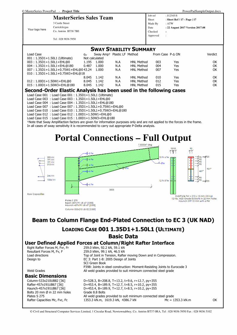
SWAY STABILITY SUMMARY Load Case αcr Sway Amp† Plastic LF Method From Case P-∆ ON Verdict 001 : 1.35D1+1.50L1 (Ultimate) Not calculated 003 : 1.35D1+1.50L1+EHL@0 1.195 1.000 N.A HNL Method 003 Yes OK 004 : 1.35D1+1.50L1+EHL@180 0.487 1.000 N.A HNL Method 004 Yes OK 007 : 1.35D1+1.50L1+0.75W1+EHL@0 43.24 1.000 N.A HNL Method 007 Yes OK 010 : 1.35D1+1.50L1+0.75W3+EHL@18 8.045 1.142 N.A HNL Method 010 Yes OK 012 : 1.00D1+1.50W1+EHL@0 8.045 1.142 N.A HNL Method 012 Yes OK 015 : 1.00D1+1.50W3+EHL@180 8.045 1.142 N.A HNL Method 015 Yes OK
Second-Order Elastic Analysis has been used in the following cases Load Case 001 : Load Case 001 : 1.35D1+1.50L1 (Ultimate) Load Case 003 : Load Case 003 : 1.35D1+1.50L1+EHL@0 Load Case 004 : Load Case 004 : 1.35D1+1.50L1+EHL@180 Load Case 007 : Load Case 007 : 1.35D1+1.50L1+0.75W1+EHL@0 Load Case 010 : Load Case 010 : 1.35D1+1.50L1+0.75W3+EHL@180 Load Case 012 : Load Case 012 : 1.00D1+1.50W1+EHL@0 Load Case 015 : Load Case 015 : 1.00D1+1.50W3+EHL@180 †Note that Sway Amplifaction factors are given for information purposes only and are not applied to the forces in the frame. In all cases of sway sensitivity it is recommended to carry out appropriate P-Delta analysis.
Portal Connections – Full Output
Beam to Column Flange End-Plated Connection to EC 3 (UK NAD)
LOADING CASE 001 1.35D1+1.50L1 (ULTIMATE)
Basic Data User Defined Applied Forces at Column/Right Rafter Interface Right Rafter Forces M, Fvr, Fr 259.0 kNm, 92.2 kN, 59.1 kN Resultant Forces M, Fv, F 259.0 kNm, 99.1 kN, 46.5 kN Load directions Top of Joint in Tension, Rafter moving Down and in Compression. Design to EC 3: Part 1-8: 2005 Design of Joints SCI Green Book P398: Joints in steel construction: Moment-Resisting Joints to Eurocode 3 Weld Grades All weld grades provided to suit minimum connected steel grade
Basic Dimensions Column-533x210UB82 [36] D=528.3, B=208.8, T=13.2, t=9.6, r=12.7, py=355 Rafter-457x191UB67 [36] D=453.4, B=189.9, T=12.7, t=8.5, r=10.2, py=355 Haunch-457x191UB67 [36] D=453.4, B=189.9, T=12.7, t=8.5, r=10.2, py=355 Bolts 20 mm Ø in 22 mm holes Grade 8.8 Bolts Plates S 275 All weld grades provided to suit minimum connected steel grade Rafter Capacities Mc, Fvc, Fc 1353.3 kN.m, 1619.3 kN, 4386.7 kN Mc = 1353.3 kN.m OK
© MasterSeries PowerPad - Project Title PowerPadSampleOutput.docx
Your logo here
MasterSeries Sales Team 3 Castle Street
Carrickfergus
Co. Antrim BT38 7BE
Job ref : J12345/S
Sheet : Sheet Ref / 18 - Page | 18
Made By : ATW
Date : 22 August 2017 Version 2017.08
Checked :
Approved : Tel : 028 9036 5950
© Civil and Structural Computer Services Limited, 1 Circular Road, Newtownabbey, Co. Antrim BT37 0RA, Tel : 028 9036 5950 Fax : 028 9036 5102
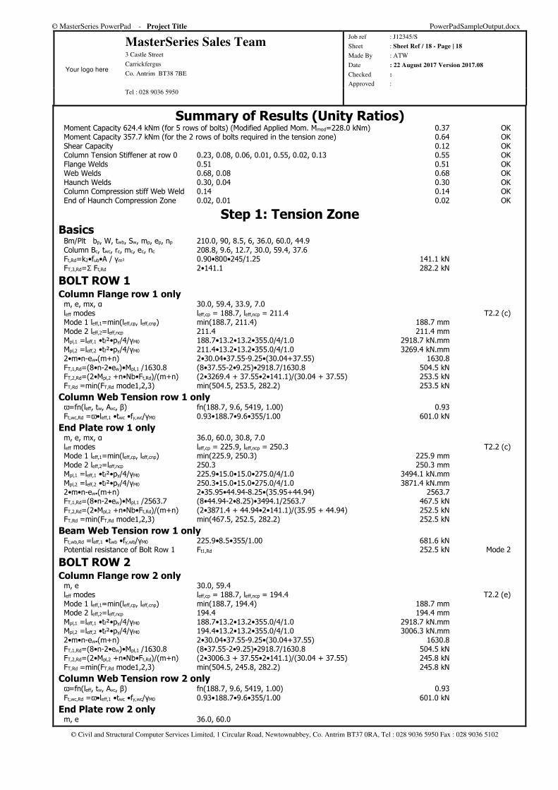
Summary of Results (Unity Ratios) Moment Capacity 624.4 kNm (for 5 rows of bolts) (Modified Applied Mom. Mmod=228.0 kNm) 0.37 OK Moment Capacity 357.7 kNm (for the 2 rows of bolts required in the tension zone) 0.64 OK Shear Capacity 0.12 OK Column Tension Stiffener at row 0 0.23, 0.08, 0.06, 0.01, 0.55, 0.02, 0.13 0.55 OK Flange Welds 0.51 0.51 OK Web Welds 0.68, 0.08 0.68 OK Haunch Welds 0.30, 0.04 0.30 OK Column Compression stiff Web Weld 0.14 0.14 OK End of Haunch Compression Zone 0.02, 0.01 0.02 OK
Step 1: Tension Zone Basics Bm/Plt bp, W, twb, Sw, mp, ep, np 210.0, 90, 8.5, 6, 36.0, 60.0, 44.9 Column Bc, twc, rc, mc, ec, nc 208.8, 9.6, 12.7, 30.0, 59.4, 37.6 Ft,Rd=k2•fub•A / γm² 0.90•800•245/1.25 141.1 kN FT,3,Rd=Σ Ft,Rd 2•141.1 282.2 kN
BOLT ROW 1 Column Flange row 1 only m, e, mx, α 30.0, 59.4, 33.9, 7.0 leff modes leff,cp = 188.7, leff,ncp = 211.4 T2.2 (c) Mode 1 leff,1=min(leff,cp, leff,cnp) min(188.7, 211.4) 188.7 mm Mode 2 leff,2=leff,ncp 211.4 211.4 mm Mpl,1 =leff,1 •tf²•py/4/γM0 188.7•13.2•13.2•355.0/4/1.0 2918.7 kN.mm Mpl,2 =leff,2 •tf²•py/4/γM0 211.4•13.2•13.2•355.0/4/1.0 3269.4 kN.mm 2•m•n-ew•(m+n) 2•30.04•37.55-9.25•(30.04+37.55) 1630.8 FT,1,Rd=(8•n-2•ew)•Mpl,1 /1630.8 (8•37.55-2•9.25)•2918.7/1630.8 504.5 kN FT,2,Rd=(2•Mpl,2 +n•Nb•Ft,Rd)/(m+n) (2•3269.4 + 37.55•2•141.1)/(30.04 + 37.55) 253.5 kN FT,Rd =min(FT,Rd mode1,2,3) min(504.5, 253.5, 282.2) 253.5 kN
Column Web Tension row 1 only ω=fn(leff, tw, Avc, β) fn(188.7, 9.6, 5419, 1.00) 0.93 Ft,wc,Rd =ω•leff,1 •twc •fy,wc/γM0 0.93•188.7•9.6•355/1.00 601.0 kN
End Plate row 1 only m, e, mx, α 36.0, 60.0, 30.8, 7.0 leff modes leff,cp = 225.9, leff,ncp = 250.3 T2.2 (c) Mode 1 leff,1=min(leff,cp, leff,cnp) min(225.9, 250.3) 225.9 mm Mode 2 leff,2=leff,ncp 250.3 250.3 mm Mpl,1 =leff,1 •tf²•py/4/γM0 225.9•15.0•15.0•275.0/4/1.0 3494.1 kN.mm Mpl,2 =leff,2 •tf²•py/4/γM0 250.3•15.0•15.0•275.0/4/1.0 3871.4 kN.mm 2•m•n-ew•(m+n) 2•35.95•44.94-8.25•(35.95+44.94) 2563.7 FT,1,Rd=(8•n-2•ew)•Mpl,1 /2563.7 (8•44.94-2•8.25)•3494.1/2563.7 467.5 kN FT,2,Rd=(2•Mpl,2 +n•Nb•Ft,Rd)/(m+n) (2•3871.4 + 44.94•2•141.1)/(35.95 + 44.94) 252.5 kN FT,Rd =min(FT,Rd mode1,2,3) min(467.5, 252.5, 282.2) 252.5 kN
Beam Web Tension row 1 only Ft,wb,Rd =leff,1 •twb •fy,wb/γM0 225.9•8.5•355/1.00 681.6 kN Potential resistance of Bolt Row 1 Ft1,Rd 252.5 kN Mode 2
BOLT ROW 2 Column Flange row 2 only m, e 30.0, 59.4 leff modes leff,cp = 188.7, leff,ncp = 194.4 T2.2 (e) Mode 1 leff,1=min(leff,cp, leff,cnp) min(188.7, 194.4) 188.7 mm Mode 2 leff,2=leff,ncp 194.4 194.4 mm Mpl,1 =leff,1 •tf²•py/4/γM0 188.7•13.2•13.2•355.0/4/1.0 2918.7 kN.mm Mpl,2 =leff,2 •tf²•py/4/γM0 194.4•13.2•13.2•355.0/4/1.0 3006.3 kN.mm 2•m•n-ew•(m+n) 2•30.04•37.55-9.25•(30.04+37.55) 1630.8 FT,1,Rd=(8•n-2•ew)•Mpl,1 /1630.8 (8•37.55-2•9.25)•2918.7/1630.8 504.5 kN FT,2,Rd=(2•Mpl,2 +n•Nb•Ft,Rd)/(m+n) (2•3006.3 + 37.55•2•141.1)/(30.04 + 37.55) 245.8 kN FT,Rd =min(FT,Rd mode1,2,3) min(504.5, 245.8, 282.2) 245.8 kN
Column Web Tension row 2 only ω=fn(leff, tw, Avc, β) fn(188.7, 9.6, 5419, 1.00) 0.93 Ft,wc,Rd =ω•leff,1 •twc •fy,wc/γM0 0.93•188.7•9.6•355/1.00 601.0 kN
End Plate row 2 only m, e 36.0, 60.0
© MasterSeries PowerPad - Project Title PowerPadSampleOutput.docx
Your logo here
MasterSeries Sales Team 3 Castle Street
Carrickfergus
Co. Antrim BT38 7BE
Job ref : J12345/S
Sheet : Sheet Ref / 19 - Page | 19
Made By : ATW
Date : 22 August 2017 Version 2017.08
Checked :
Approved : Tel : 028 9036 5950
© Civil and Structural Computer Services Limited, 1 Circular Road, Newtownabbey, Co. Antrim BT37 0RA, Tel : 028 9036 5950 Fax : 028 9036 5102
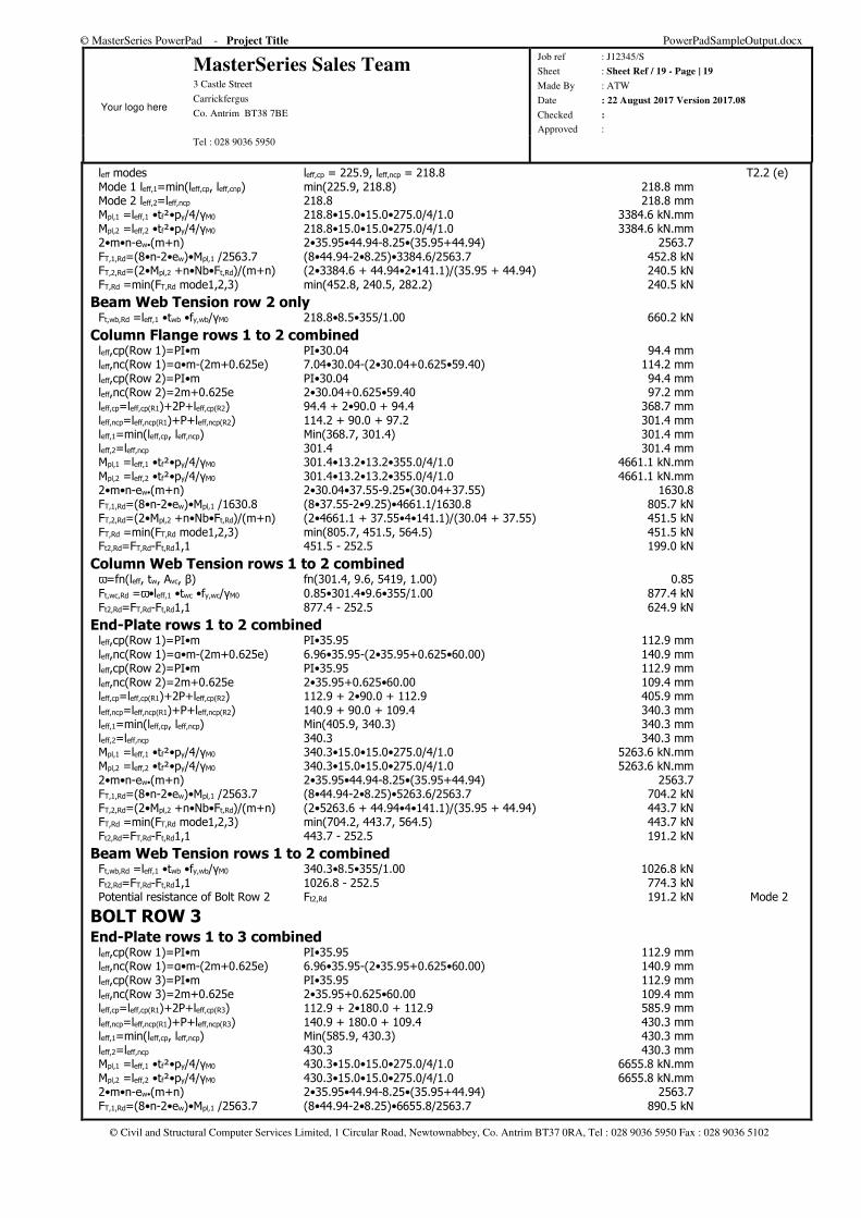
leff modes leff,cp = 225.9, leff,ncp = 218.8 T2.2 (e) Mode 1 leff,1=min(leff,cp, leff,cnp) min(225.9, 218.8) 218.8 mm Mode 2 leff,2=leff,ncp 218.8 218.8 mm Mpl,1 =leff,1 •tf²•py/4/γM0 218.8•15.0•15.0•275.0/4/1.0 3384.6 kN.mm Mpl,2 =leff,2 •tf²•py/4/γM0 218.8•15.0•15.0•275.0/4/1.0 3384.6 kN.mm 2•m•n-ew•(m+n) 2•35.95•44.94-8.25•(35.95+44.94) 2563.7 FT,1,Rd=(8•n-2•ew)•Mpl,1 /2563.7 (8•44.94-2•8.25)•3384.6/2563.7 452.8 kN FT,2,Rd=(2•Mpl,2 +n•Nb•Ft,Rd)/(m+n) (2•3384.6 + 44.94•2•141.1)/(35.95 + 44.94) 240.5 kN FT,Rd =min(FT,Rd mode1,2,3) min(452.8, 240.5, 282.2) 240.5 kN
Beam Web Tension row 2 only Ft,wb,Rd =leff,1 •twb •fy,wb/γM0 218.8•8.5•355/1.00 660.2 kN
Column Flange rows 1 to 2 combined leff,cp(Row 1)=PI•m PI•30.04 94.4 mm leff,nc(Row 1)=α•m-(2m+0.625e) 7.04•30.04-(2•30.04+0.625•59.40) 114.2 mm leff,cp(Row 2)=PI•m PI•30.04 94.4 mm leff,nc(Row 2)=2m+0.625e 2•30.04+0.625•59.40 97.2 mm leff,cp=leff,cp(R1)+2P+leff,cp(R2) 94.4 + 2•90.0 + 94.4 368.7 mm leff,ncp=leff,ncp(R1)+P+leff,ncp(R2) 114.2 + 90.0 + 97.2 301.4 mm leff,1=min(leff,cp, leff,ncp) Min(368.7, 301.4) 301.4 mm leff,2=leff,ncp 301.4 301.4 mm Mpl,1 =leff,1 •tf²•py/4/γM0 301.4•13.2•13.2•355.0/4/1.0 4661.1 kN.mm Mpl,2 =leff,2 •tf²•py/4/γM0 301.4•13.2•13.2•355.0/4/1.0 4661.1 kN.mm 2•m•n-ew•(m+n) 2•30.04•37.55-9.25•(30.04+37.55) 1630.8 FT,1,Rd=(8•n-2•ew)•Mpl,1 /1630.8 (8•37.55-2•9.25)•4661.1/1630.8 805.7 kN FT,2,Rd=(2•Mpl,2 +n•Nb•Ft,Rd)/(m+n) (2•4661.1 + 37.55•4•141.1)/(30.04 + 37.55) 451.5 kN FT,Rd =min(FT,Rd mode1,2,3) min(805.7, 451.5, 564.5) 451.5 kN Ft2,Rd=FT,Rd-Ft,Rd1,1 451.5 - 252.5 199.0 kN
Column Web Tension rows 1 to 2 combined ω=fn(leff, tw, Avc, β) fn(301.4, 9.6, 5419, 1.00) 0.85 Ft,wc,Rd =ω•leff,1 •twc •fy,wc/γM0 0.85•301.4•9.6•355/1.00 877.4 kN Ft2,Rd=FT,Rd-Ft,Rd1,1 877.4 - 252.5 624.9 kN
End-Plate rows 1 to 2 combined leff,cp(Row 1)=PI•m PI•35.95 112.9 mm leff,nc(Row 1)=α•m-(2m+0.625e) 6.96•35.95-(2•35.95+0.625•60.00) 140.9 mm leff,cp(Row 2)=PI•m PI•35.95 112.9 mm leff,nc(Row 2)=2m+0.625e 2•35.95+0.625•60.00 109.4 mm leff,cp=leff,cp(R1)+2P+leff,cp(R2) 112.9 + 2•90.0 + 112.9 405.9 mm leff,ncp=leff,ncp(R1)+P+leff,ncp(R2) 140.9 + 90.0 + 109.4 340.3 mm leff,1=min(leff,cp, leff,ncp) Min(405.9, 340.3) 340.3 mm leff,2=leff,ncp 340.3 340.3 mm Mpl,1 =leff,1 •tf²•py/4/γM0 340.3•15.0•15.0•275.0/4/1.0 5263.6 kN.mm Mpl,2 =leff,2 •tf²•py/4/γM0 340.3•15.0•15.0•275.0/4/1.0 5263.6 kN.mm 2•m•n-ew•(m+n) 2•35.95•44.94-8.25•(35.95+44.94) 2563.7 FT,1,Rd=(8•n-2•ew)•Mpl,1 /2563.7 (8•44.94-2•8.25)•5263.6/2563.7 704.2 kN FT,2,Rd=(2•Mpl,2 +n•Nb•Ft,Rd)/(m+n) (2•5263.6 + 44.94•4•141.1)/(35.95 + 44.94) 443.7 kN FT,Rd =min(FT,Rd mode1,2,3) min(704.2, 443.7, 564.5) 443.7 kN Ft2,Rd=FT,Rd-Ft,Rd1,1 443.7 - 252.5 191.2 kN
Beam Web Tension rows 1 to 2 combined Ft,wb,Rd =leff,1 •twb •fy,wb/γM0 340.3•8.5•355/1.00 1026.8 kN Ft2,Rd=FT,Rd-Ft,Rd1,1 1026.8 - 252.5 774.3 kN Potential resistance of Bolt Row 2 Ft2,Rd 191.2 kN Mode 2
BOLT ROW 3 End-Plate rows 1 to 3 combined leff,cp(Row 1)=PI•m PI•35.95 112.9 mm leff,nc(Row 1)=α•m-(2m+0.625e) 6.96•35.95-(2•35.95+0.625•60.00) 140.9 mm leff,cp(Row 3)=PI•m PI•35.95 112.9 mm leff,nc(Row 3)=2m+0.625e 2•35.95+0.625•60.00 109.4 mm leff,cp=leff,cp(R1)+2P+leff,cp(R3) 112.9 + 2•180.0 + 112.9 585.9 mm leff,ncp=leff,ncp(R1)+P+leff,ncp(R3) 140.9 + 180.0 + 109.4 430.3 mm leff,1=min(leff,cp, leff,ncp) Min(585.9, 430.3) 430.3 mm leff,2=leff,ncp 430.3 430.3 mm Mpl,1 =leff,1 •tf²•py/4/γM0 430.3•15.0•15.0•275.0/4/1.0 6655.8 kN.mm Mpl,2 =leff,2 •tf²•py/4/γM0 430.3•15.0•15.0•275.0/4/1.0 6655.8 kN.mm 2•m•n-ew•(m+n) 2•35.95•44.94-8.25•(35.95+44.94) 2563.7 FT,1,Rd=(8•n-2•ew)•Mpl,1 /2563.7 (8•44.94-2•8.25)•6655.8/2563.7 890.5 kN
© MasterSeries PowerPad - Project Title PowerPadSampleOutput.docx
Your logo here
MasterSeries Sales Team 3 Castle Street
Carrickfergus
Co. Antrim BT38 7BE
Job ref : J12345/S
Sheet : Sheet Ref / 20 - Page | 20
Made By : ATW
Date : 22 August 2017 Version 2017.08
Checked :
Approved : Tel : 028 9036 5950
© Civil and Structural Computer Services Limited, 1 Circular Road, Newtownabbey, Co. Antrim BT37 0RA, Tel : 028 9036 5950 Fax : 028 9036 5102
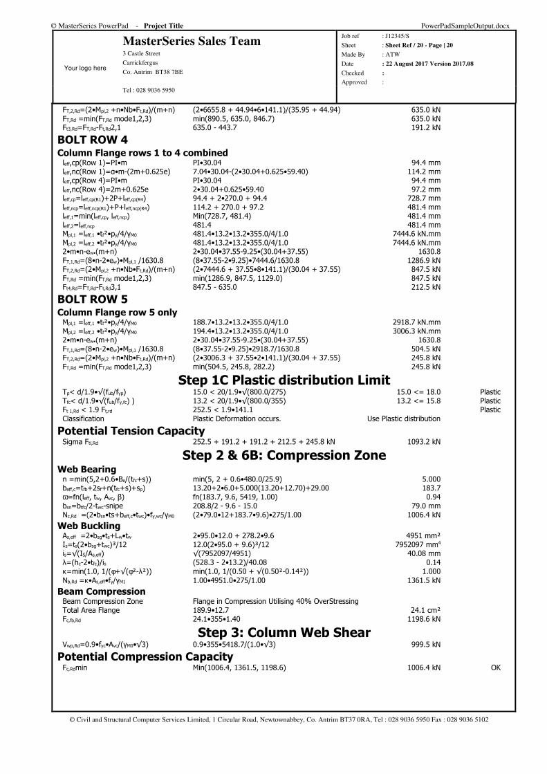
FT,2,Rd=(2•Mpl,2 +n•Nb•Ft,Rd)/(m+n) (2•6655.8 + 44.94•6•141.1)/(35.95 + 44.94) 635.0 kN FT,Rd =min(FT,Rd mode1,2,3) min(890.5, 635.0, 846.7) 635.0 kN Ft3,Rd=FT,Rd-Ft,Rd2,1 635.0 - 443.7 191.2 kN
BOLT ROW 4 Column Flange rows 1 to 4 combined leff,cp(Row 1)=PI•m PI•30.04 94.4 mm leff,nc(Row 1)=α•m-(2m+0.625e) 7.04•30.04-(2•30.04+0.625•59.40) 114.2 mm leff,cp(Row 4)=PI•m PI•30.04 94.4 mm leff,nc(Row 4)=2m+0.625e 2•30.04+0.625•59.40 97.2 mm leff,cp=leff,cp(R1)+2P+leff,cp(R4) 94.4 + 2•270.0 + 94.4 728.7 mm leff,ncp=leff,ncp(R1)+P+leff,ncp(R4) 114.2 + 270.0 + 97.2 481.4 mm leff,1=min(leff,cp, leff,ncp) Min(728.7, 481.4) 481.4 mm leff,2=leff,ncp 481.4 481.4 mm Mpl,1 =leff,1 •tf²•py/4/γM0 481.4•13.2•13.2•355.0/4/1.0 7444.6 kN.mm Mpl,2 =leff,2 •tf²•py/4/γM0 481.4•13.2•13.2•355.0/4/1.0 7444.6 kN.mm 2•m•n-ew•(m+n) 2•30.04•37.55-9.25•(30.04+37.55) 1630.8 FT,1,Rd=(8•n-2•ew)•Mpl,1 /1630.8 (8•37.55-2•9.25)•7444.6/1630.8 1286.9 kN FT,2,Rd=(2•Mpl,2 +n•Nb•Ft,Rd)/(m+n) (2•7444.6 + 37.55•8•141.1)/(30.04 + 37.55) 847.5 kN FT,Rd =min(FT,Rd mode1,2,3) min(1286.9, 847.5, 1129.0) 847.5 kN Ft4,Rd=FT,Rd-Ft,Rd3,1 847.5 - 635.0 212.5 kN
BOLT ROW 5 Column Flange row 5 only Mpl,1 =leff,1 •tf²•py/4/γM0 188.7•13.2•13.2•355.0/4/1.0 2918.7 kN.mm Mpl,2 =leff,2 •tf²•py/4/γM0 194.4•13.2•13.2•355.0/4/1.0 3006.3 kN.mm 2•m•n-ew•(m+n) 2•30.04•37.55-9.25•(30.04+37.55) 1630.8 FT,1,Rd=(8•n-2•ew)•Mpl,1 /1630.8 (8•37.55-2•9.25)•2918.7/1630.8 504.5 kN FT,2,Rd=(2•Mpl,2 +n•Nb•Ft,Rd)/(m+n) (2•3006.3 + 37.55•2•141.1)/(30.04 + 37.55) 245.8 kN FT,Rd =min(FT,Rd mode1,2,3) min(504.5, 245.8, 282.2) 245.8 kN
Step 1C Plastic distribution Limit Tp< d/1.9•√(fub/fyp) 15.0 < 20/1.9•√(800.0/275) 15.0 <= 18.0 Plastic Tfc< d/1.9•√(fub/fy,fc) ) 13.2 < 20/1.9•√(800.0/355) 13.2 <= 15.8 Plastic Ft 1,Rd < 1.9 Ft,rd 252.5 < 1.9•141.1 Plastic Classification Plastic Deformation occurs. Use Plastic distribution
Potential Tension Capacity Sigma Fti,Rd 252.5 + 191.2 + 191.2 + 212.5 + 245.8 kN 1093.2 kN
Step 2 & 6B: Compression Zone Web Bearing n =min(5,2+0.6•Be/(tfc+s)) min(5, 2 + 0.6•480.0/25.9) 5.000 beff,c=tfb+2sf+n(tfc+s)+sp) 13.20+2•6.0+5.000(13.20+12.70)+29.00 183.7 ω=fn(leff, tw, Avc, β) fn(183.7, 9.6, 5419, 1.00) 0.94 bsn=btfc/2-twc-snipe 208.8/2 - 9.6 - 15.0 79.0 mm Nc,Rd =(2•bsn•ts+beff,c•twc)•fy,wc/γM0 (2•79.0•12+183.7•9.6)•275/1.00 1006.4 kN
Web Buckling As,eff =2•bsg•ts+Lw•tw 2•95.0•12.0 + 278.2•9.6 4951 mm² Is=ts(2•bsg+twc)³/12 12.0(2•95.0 + 9.6)³/12 7952097 mm4 is=√(IS/As,eff) √(7952097/4951) 40.08 mm λ=(hc-2•tfc)/is (528.3 - 2•13.2)/40.08 0.14 κ=min(1.0, 1/(φ+√(φ²-λ²)) min(1.0, 1/(0.50 + √(0.50²-0.14²)) 1.000 Nb,Rd =κ•As,eff•fy/γM1 1.00•4951.0•275/1.00 1361.5 kN
Beam Compression Beam Compression Zone Flange in Compression Utilising 40% OverStressing Total Area Flange 189.9•12.7 24.1 cm² Fc,fb,Rd 24.1•355•1.40 1198.6 kN
Step 3: Column Web Shear Vwp,Rd=0.9•fyc•Avc/(γM0•√3) 0.9•355•5418.7/(1.0•√3) 999.5 kN
Potential Compression Capacity Fc,Rdmin Min(1006.4, 1361.5, 1198.6) 1006.4 kN OK
© MasterSeries PowerPad - Project Title PowerPadSampleOutput.docx
Your logo here
MasterSeries Sales Team 3 Castle Street
Carrickfergus
Co. Antrim BT38 7BE
Job ref : J12345/S
Sheet : Sheet Ref / 21 - Page | 21
Made By : ATW
Date : 22 August 2017 Version 2017.08
Checked :
Approved : Tel : 028 9036 5950
© Civil and Structural Computer Services Limited, 1 Circular Road, Newtownabbey, Co. Antrim BT37 0RA, Tel : 028 9036 5950 Fax : 028 9036 5102
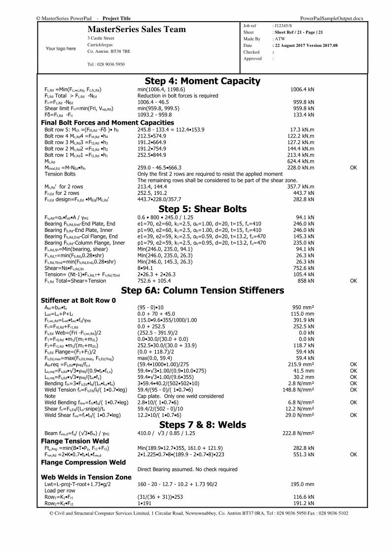
Step 4: Moment Capacity Fc,Rd =Min(Fc,wc,Rd, Fc,fc,Rd) min(1006.4, 1198.6) 1006.4 kN Ft,Rd Total > Fc,Rd -NEd Reduction in bolt forces is required Fri=Fc,Rd -NEd 1006.4 - 46.5 959.8 kN Shear limit Fri=min(Fri, Vwp,Rd) min(959.8, 999.5) 959.8 kN Fδ=Ft,Rd -Fri 1093.2 - 959.8 133.4 kN
Final Bolt Forces and Moment Capacities Bolt row 5: Mc5 =(Ft5,Rd -Fδ )• h5 245.8 - 133.4 = 112.4•153.9 17.3 kN.m Bolt row 4 Mc,Rd4 =Ft4,Rd •h4 212.5•574.9 122.2 kN.m Bolt row 3 Mc,Rd3 =Ft3,Rd •h3 191.2•664.9 127.2 kN.m Bolt row 2 Mc,Rd2 =Ft2,Rd •h2 191.2•754.9 144.4 kN.m Bolt row 1 Mc,Rd1 =Ft1,Rd •h1 252.5•844.9 213.4 kN.m Mc,Rd 624.4 kN.m Mmod,Ed =M-NEd•hn 259.0 - 46.5•666.3 228.0 kN.m OK Tension Bolts Only the first 2 rows are required to resist the applied moment The remaining rows shall be considered to be part of the shear zone. Mc,Rd' for 2 rows 213.4, 144.4 357.7 kN.m Fri,Ed for 2 rows 252.5, 191.2 443.7 kN Fri,Ed design=Fri,Ed •MEd/Mc,Rd' 443.7•228.0/357.7 282.8 kN
Step 5: Shear Bolts Fv,Rd=αv•fub•A / γM2 0.6 • 800 • 245.0 / 1.25 94.1 kN Bearing Fb,Rd,End-End Plate, End e1=70, e2=60, k1=2.5, αb=1.00, d=20, t=15, fu=410 246.0 kN Bearing Fb,Rd-End Plate, Inner p1=90, e2=60, k1=2.5, αb=1.00, d=20, t=15, fu=410 246.0 kN Bearing Fb,Rd,End-Col Flange, End e1=39, e2=59, k1=2.5, αb=0.59, d=20, t=13.2, fu=470 145.3 kN Bearing Fb,Rd-Column Flange, Inner p1=79, e2=59, k1=2.5, αb=0.95, d=20, t=13.2, fu=470 235.0 kN Fv,Rd,Sh=Min(bearing, shear) Min(246.0, 235.0, 94.1) 94.1 kN Fv,Rd,T=min(Fb,Rd,0.28•shr) Min(246.0, 235.0, 26.3) 26.3 kN Fv,Rd,TEnd=min(Fb,Rd,End,0.28•shr) Min(246.0, 145.3, 26.3) 26.3 kN Shear=Ns•Fv,Rd,Sh 8•94.1 752.6 kN Tension= (Nt-1)•Fv,Rd,T+ Fv,Rd,TEnd 2•26.3 + 2•26.3 105.4 kN Fv,Rd Total=Shear+Tension 752.6 + 105.4 858 kN OK
Step 6A: Column Tension Stiffeners Stiffener at Bolt Row 0 Asn=bsn•ts (95 - 0)•10 950 mm² Lwt=Lu+P+Ll 0.0 + 70 + 45.0 115.0 mm Ft,wc,Rd=Lwt•twc•fy/γM0 115.0•9.6•355/1000/1.00 391.9 kN Fri=Fr0,Rd+Fr1,Rd 0.0 + 252.5 252.5 kN Fs,Ed Web=(Fri -Ft,wc,Rd)/2 (252.5 - 391.9)/2 0.0 kN F1=Fr0,Rd •m1/(m1+m2L) 0.0•30.0/(30.0 + 0.0) 0.0 kN F2=Fr1,Rd •m1/(m1+m2U) 252.5•30.0/(30.0 + 33.9) 118.7 kN Fs,Ed Flange=(F1+F2)/2 (0.0 + 118.7)/2 59.4 kN Fs,Ed,max=max(Fs,Ed,Web, Fs,Ed,Flng) max(0.0, 59.4) 59.4 kN Asnreq =Fs,Ed•γM0/fy,s (59.4•1000•1.00)/275 215.9 mm² OK Ls,req=Fs,Ed•√3•γM0/(0.9•ts•fy,s) 59.4•√3•1.00/(0.9•10.0•275) 41.5 mm OK Ls,req=Fs,Ed•√3•γM0/(tw•fy) 59.4•√3•1.00/(9.6•355) 30.2 mm OK Bending fm=3•Fs,Ed•la/(Ls•Ls•ts) 3•59.4•40.2/(502•502•10) 2.8 N/mm² OK Weld Tension fs=Fs,Ed/lt/( 1•0.7•leg) 59.4/(95 - 0)/( 1•0.7•6) 148.8 N/mm² OK Note Cap plate. Only one weld considered Weld Bending fmw=fm•ts/( 1•0.7•leg) 2.8•10/( 1•0.7•6) 6.8 N/mm² OK Shear fv=Fs,Ed/(Ls-snipe)/ts 59.4/2/(502 - 0)/10 12.2 N/mm² Weld Shear fvw=fv•ts/( 1•0.7•leg) 12.2•10/( 1•0.7•6) 29.0 N/mm² OK
Steps 7 & 8: Welds Beam fvw,d=fu/ (√3•ßw) / γM2 410.0 / √3 / 0.85 / 1.25 222.8 N/mm²
Flange Tension Weld Ft,,flng =min(B•T•Py, Fr1+Fr2) Min(189.9•12.7•355, 161.0 + 121.9) 282.8 kN Fvw,Rd =2•K•0.7•ts•L•fvw,d 2•1.225•0.7•8•(189.9 - 2•0.7•8)•223 551.3 kN OK
Flange Compression Weld Direct Bearing assumed. No check required
Web Welds in Tension Zone Lwt=L-proj-T-root+1.73•g/2 160 - 20 - 12.7 - 10.2 + 1.73 90/2 195.0 mm Load per row Row1=K1•Fr1 (31/(36 + 31))•253 116.6 kN Row2=K2•Fr2 1•191 191.2 kN
© MasterSeries PowerPad - Project Title PowerPadSampleOutput.docx
Your logo here
MasterSeries Sales Team 3 Castle Street
Carrickfergus
Co. Antrim BT38 7BE
Job ref : J12345/S
Sheet : Sheet Ref / 22 - Page | 22
Made By : ATW
Date : 22 August 2017 Version 2017.08
Checked :
Approved : Tel : 028 9036 5950
© Civil and Structural Computer Services Limited, 1 Circular Road, Newtownabbey, Co. Antrim BT37 0RA, Tel : 028 9036 5950 Fax : 028 9036 5102
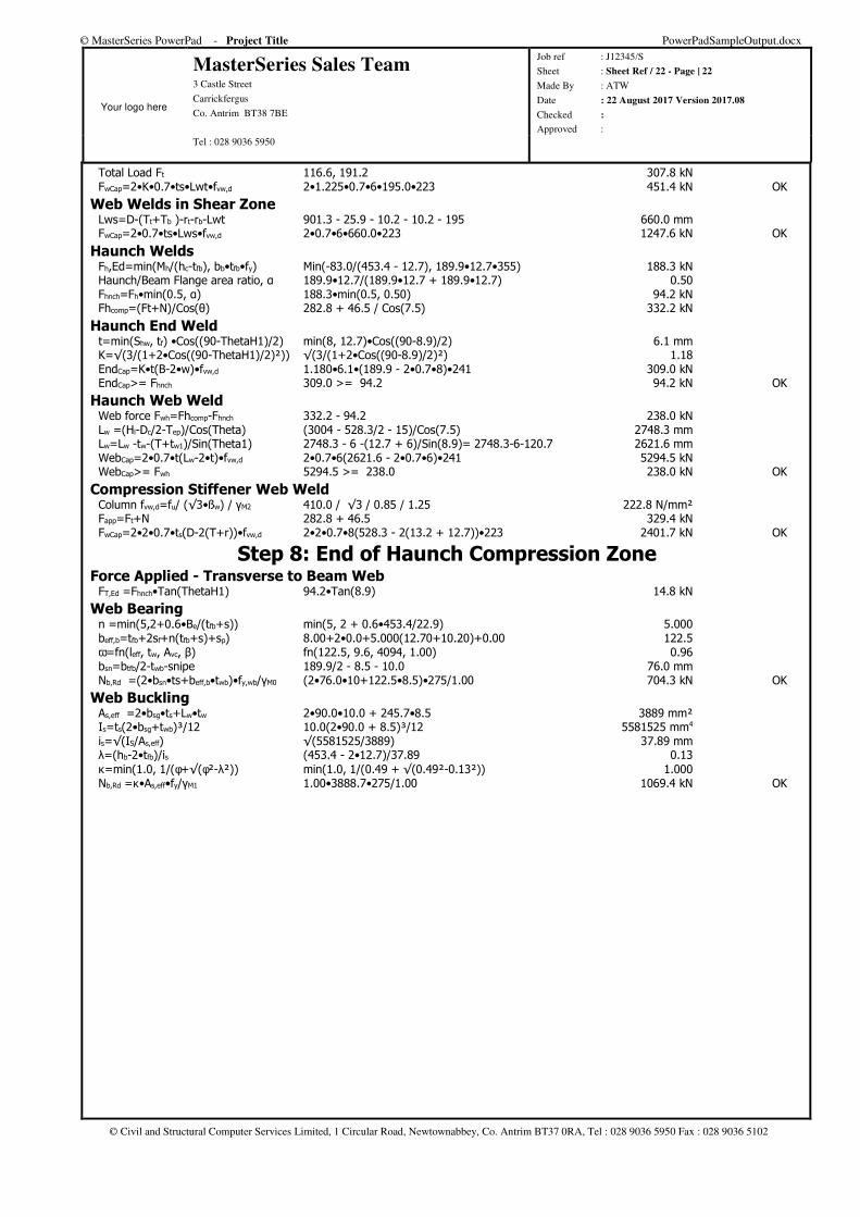
Total Load Ft 116.6, 191.2 307.8 kN FwCap=2•K•0.7•ts•Lwt•fvw,d 2•1.225•0.7•6•195.0•223 451.4 kN OK
Web Welds in Shear Zone Lws=D-(Tt+Tb )-rt-rb-Lwt 901.3 - 25.9 - 10.2 - 10.2 - 195 660.0 mm FwCap=2•0.7•ts•Lws•fvw,d 2•0.7•6•660.0•223 1247.6 kN OK
Haunch Welds Fh,Ed=min(Mh/(hc-tfb), bb•tfb•fy) Min(-83.0/(453.4 - 12.7), 189.9•12.7•355) 188.3 kN Haunch/Beam Flange area ratio, α 189.9•12.7/(189.9•12.7 + 189.9•12.7) 0.50 Fhnch=Fh•min(0.5, α) 188.3•min(0.5, 0.50) 94.2 kN Fhcomp=(Ft+N)/Cos(θ) 282.8 + 46.5 / Cos(7.5) 332.2 kN
Haunch End Weld t=min(Shw, tf) •Cos((90-ThetaH1)/2) min(8, 12.7)•Cos((90-8.9)/2) 6.1 mm K=√(3/(1+2•Cos((90-ThetaH1)/2)²)) √(3/(1+2•Cos((90-8.9)/2)²) 1.18 EndCap=K•t(B-2•w)•fvw,d 1.180•6.1•(189.9 - 2•0.7•8)•241 309.0 kN EndCap>= Fhnch 309.0 >= 94.2 94.2 kN OK
Haunch Web Weld Web force Fwh=Fhcomp-Fhnch 332.2 - 94.2 238.0 kN Lw =(Hl-Dc/2-Tep)/Cos(Τheta) (3004 - 528.3/2 - 15)/Cos(7.5) 2748.3 mm Lw=Lw -tw-(T+tw1)/Sin(Theta1) 2748.3 - 6 -(12.7 + 6)/Sin(8.9)= 2748.3-6-120.7 2621.6 mm WebCap=2•0.7•t(Lw-2•t)•fvw,d 2•0.7•6(2621.6 - 2•0.7•6)•241 5294.5 kN WebCap>= Fwh 5294.5 >= 238.0 238.0 kN OK
Compression Stiffener Web Weld Column fvw,d=fu/ (√3•ßw) / γM2 410.0 / √3 / 0.85 / 1.25 222.8 N/mm² Fapp=Ft+N 282.8 + 46.5 329.4 kN FwCap=2•2•0.7•ts(D-2(T+r))•fvw,d 2•2•0.7•8(528.3 - 2(13.2 + 12.7))•223 2401.7 kN OK
Step 8: End of Haunch Compression Zone Force Applied - Transverse to Beam Web FT,Ed =Fhnch•Tan(ThetaH1) 94.2•Tan(8.9) 14.8 kN
Web Bearing n =min(5,2+0.6•Be/(tfb+s)) min(5, 2 + 0.6•453.4/22.9) 5.000 beff,b=tfb+2sf+n(tfb+s)+sp) 8.00+2•0.0+5.000(12.70+10.20)+0.00 122.5 ω=fn(leff, tw, Avc, β) fn(122.5, 9.6, 4094, 1.00) 0.96 bsn=btfb/2-twb-snipe 189.9/2 - 8.5 - 10.0 76.0 mm Nb,Rd =(2•bsn•ts+beff,b•twb)•fy,wb/γM0 (2•76.0•10+122.5•8.5)•275/1.00 704.3 kN OK
Web Buckling As,eff =2•bsg•ts+Lw•tw 2•90.0•10.0 + 245.7•8.5 3889 mm² Is=ts(2•bsg+twb)³/12 10.0(2•90.0 + 8.5)³/12 5581525 mm4 is=√(IS/As,eff) √(5581525/3889) 37.89 mm λ=(hb-2•tfb)/is (453.4 - 2•12.7)/37.89 0.13 κ=min(1.0, 1/(φ+√(φ²-λ²)) min(1.0, 1/(0.49 + √(0.49²-0.13²)) 1.000 Nb,Rd =κ•As,eff•fy/γM1 1.00•3888.7•275/1.00 1069.4 kN OK
© MasterSeries PowerPad - Project Title PowerPadSampleOutput.docx
Your logo here
MasterSeries Sales Team 3 Castle Street
Carrickfergus
Co. Antrim BT38 7BE
Job ref : J12345/S
Sheet : Sheet Ref / 23 - Page | 23
Made By : ATW
Date : 22 August 2017 Version 2017.08
Checked :
Approved : Tel : 028 9036 5950
© Civil and Structural Computer Services Limited, 1 Circular Road, Newtownabbey, Co. Antrim BT37 0RA, Tel : 028 9036 5950 Fax : 028 9036 5102
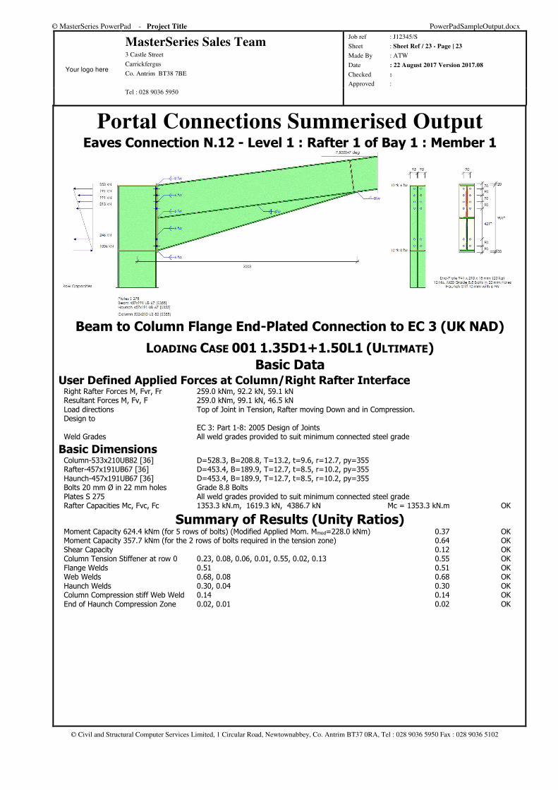
Portal Connections Summerised Output Eaves Connection N.12 - Level 1 : Rafter 1 of Bay 1 : Member 1
Beam to Column Flange End-Plated Connection to EC 3 (UK NAD)
LOADING CASE 001 1.35D1+1.50L1 (ULTIMATE)
Basic Data User Defined Applied Forces at Column/Right Rafter Interface Right Rafter Forces M, Fvr, Fr 259.0 kNm, 92.2 kN, 59.1 kN Resultant Forces M, Fv, F 259.0 kNm, 99.1 kN, 46.5 kN Load directions Top of Joint in Tension, Rafter moving Down and in Compression. Design to EC 3: Part 1-8: 2005 Design of Joints Weld Grades All weld grades provided to suit minimum connected steel grade
Basic Dimensions Column-533x210UB82 [36] D=528.3, B=208.8, T=13.2, t=9.6, r=12.7, py=355 Rafter-457x191UB67 [36] D=453.4, B=189.9, T=12.7, t=8.5, r=10.2, py=355 Haunch-457x191UB67 [36] D=453.4, B=189.9, T=12.7, t=8.5, r=10.2, py=355 Bolts 20 mm Ø in 22 mm holes Grade 8.8 Bolts Plates S 275 All weld grades provided to suit minimum connected steel grade Rafter Capacities Mc, Fvc, Fc 1353.3 kN.m, 1619.3 kN, 4386.7 kN Mc = 1353.3 kN.m OK
Summary of Results (Unity Ratios) Moment Capacity 624.4 kNm (for 5 rows of bolts) (Modified Applied Mom. Mmod=228.0 kNm) 0.37 OK Moment Capacity 357.7 kNm (for the 2 rows of bolts required in the tension zone) 0.64 OK Shear Capacity 0.12 OK Column Tension Stiffener at row 0 0.23, 0.08, 0.06, 0.01, 0.55, 0.02, 0.13 0.55 OK Flange Welds 0.51 0.51 OK Web Welds 0.68, 0.08 0.68 OK Haunch Welds 0.30, 0.04 0.30 OK Column Compression stiff Web Weld 0.14 0.14 OK End of Haunch Compression Zone 0.02, 0.01 0.02 OK
© MasterSeries PowerPad - Project Title PowerPadSampleOutput.docx
Your logo here
MasterSeries Sales Team 3 Castle Street
Carrickfergus
Co. Antrim BT38 7BE
Job ref : J12345/S
Sheet : Sheet Ref / 24 - Page | 24
Made By : ATW
Date : 22 August 2017 Version 2017.08
Checked :
Approved : Tel : 028 9036 5950
© Civil and Structural Computer Services Limited, 1 Circular Road, Newtownabbey, Co. Antrim BT37 0RA, Tel : 028 9036 5950 Fax : 028 9036 5102
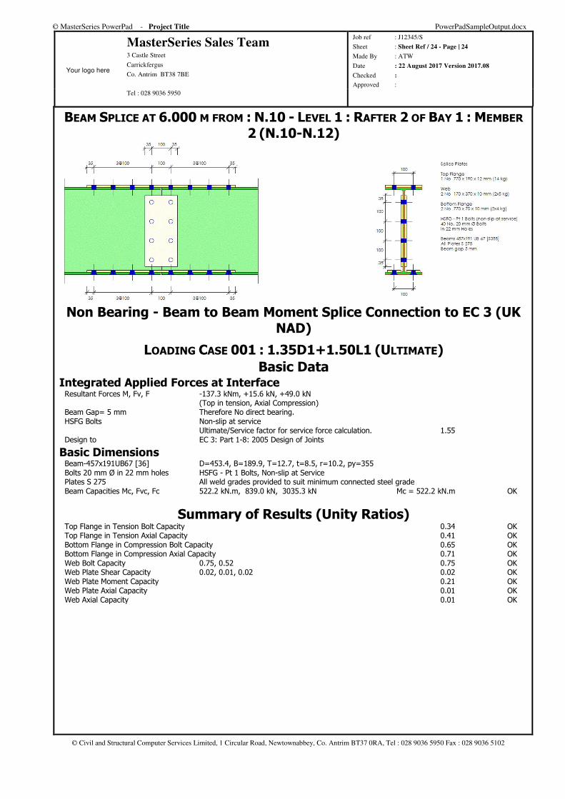
BEAM SPLICE AT 6.000 M FROM : N.10 - LEVEL 1 : RAFTER 2 OF BAY 1 : MEMBER
2 (N.10-N.12)
Non Bearing - Beam to Beam Moment Splice Connection to EC 3 (UK NAD)
LOADING CASE 001 : 1.35D1+1.50L1 (ULTIMATE)
Basic Data Integrated Applied Forces at Interface Resultant Forces M, Fv, F -137.3 kNm, +15.6 kN, +49.0 kN (Top in tension, Axial Compression) Beam Gap= 5 mm Therefore No direct bearing. HSFG Bolts Non-slip at service Ultimate/Service factor for service force calculation. 1.55 Design to EC 3: Part 1-8: 2005 Design of Joints
Basic Dimensions Beam-457x191UB67 [36] D=453.4, B=189.9, T=12.7, t=8.5, r=10.2, py=355 Bolts 20 mm Ø in 22 mm holes HSFG - Pt 1 Bolts, Non-slip at Service Plates S 275 All weld grades provided to suit minimum connected steel grade Beam Capacities Mc, Fvc, Fc 522.2 kN.m, 839.0 kN, 3035.3 kN Mc = 522.2 kN.m OK
Summary of Results (Unity Ratios) Top Flange in Tension Bolt Capacity 0.34 OK Top Flange in Tension Axial Capacity 0.41 OK Bottom Flange in Compression Bolt Capacity 0.65 OK Bottom Flange in Compression Axial Capacity 0.71 OK Web Bolt Capacity 0.75, 0.52 0.75 OK Web Plate Shear Capacity 0.02, 0.01, 0.02 0.02 OK Web Plate Moment Capacity 0.21 OK Web Plate Axial Capacity 0.01 OK Web Axial Capacity 0.01 OK
© MasterSeries PowerPad - Project Title PowerPadSampleOutput.docx
Your logo here
MasterSeries Sales Team 3 Castle Street
Carrickfergus
Co. Antrim BT38 7BE
Job ref : J12345/S
Sheet : Sheet Ref / 25 - Page | 25
Made By : ATW
Date : 22 August 2017 Version 2017.08
Checked :
Approved : Tel : 028 9036 5950
© Civil and Structural Computer Services Limited, 1 Circular Road, Newtownabbey, Co. Antrim BT37 0RA, Tel : 028 9036 5950 Fax : 028 9036 5102
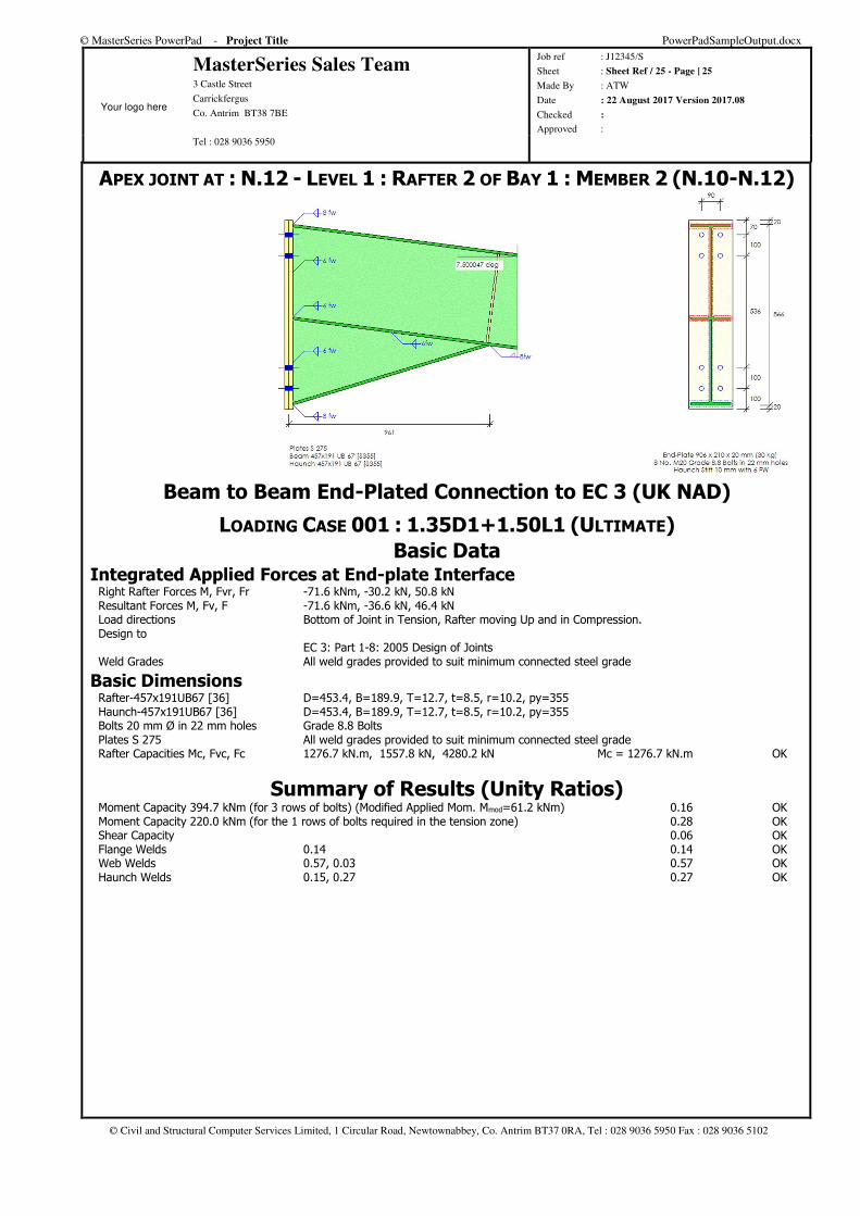
APEX JOINT AT : N.12 - LEVEL 1 : RAFTER 2 OF BAY 1 : MEMBER 2 (N.10-N.12)
Beam to Beam End-Plated Connection to EC 3 (UK NAD)
LOADING CASE 001 : 1.35D1+1.50L1 (ULTIMATE)
Basic Data Integrated Applied Forces at End-plate Interface Right Rafter Forces M, Fvr, Fr -71.6 kNm, -30.2 kN, 50.8 kN Resultant Forces M, Fv, F -71.6 kNm, -36.6 kN, 46.4 kN Load directions Bottom of Joint in Tension, Rafter moving Up and in Compression. Design to EC 3: Part 1-8: 2005 Design of Joints Weld Grades All weld grades provided to suit minimum connected steel grade
Basic Dimensions Rafter-457x191UB67 [36] D=453.4, B=189.9, T=12.7, t=8.5, r=10.2, py=355 Haunch-457x191UB67 [36] D=453.4, B=189.9, T=12.7, t=8.5, r=10.2, py=355 Bolts 20 mm Ø in 22 mm holes Grade 8.8 Bolts Plates S 275 All weld grades provided to suit minimum connected steel grade Rafter Capacities Mc, Fvc, Fc 1276.7 kN.m, 1557.8 kN, 4280.2 kN Mc = 1276.7 kN.m OK
Summary of Results (Unity Ratios) Moment Capacity 394.7 kNm (for 3 rows of bolts) (Modified Applied Mom. Mmod=61.2 kNm) 0.16 OK Moment Capacity 220.0 kNm (for the 1 rows of bolts required in the tension zone) 0.28 OK Shear Capacity 0.06 OK Flange Welds 0.14 0.14 OK Web Welds 0.57, 0.03 0.57 OK Haunch Welds 0.15, 0.27 0.27 OK
© MasterSeries PowerPad - Project Title PowerPadSampleOutput.docx
Your logo here
MasterSeries Sales Team 3 Castle Street
Carrickfergus
Co. Antrim BT38 7BE
Job ref : J12345/S
Sheet : Sheet Ref / 26 - Page | 26
Made By : ATW
Date : 22 August 2017 Version 2017.08
Checked :
Approved : Tel : 028 9036 5950
© Civil and Structural Computer Services Limited, 1 Circular Road, Newtownabbey, Co. Antrim BT37 0RA, Tel : 028 9036 5950 Fax : 028 9036 5102
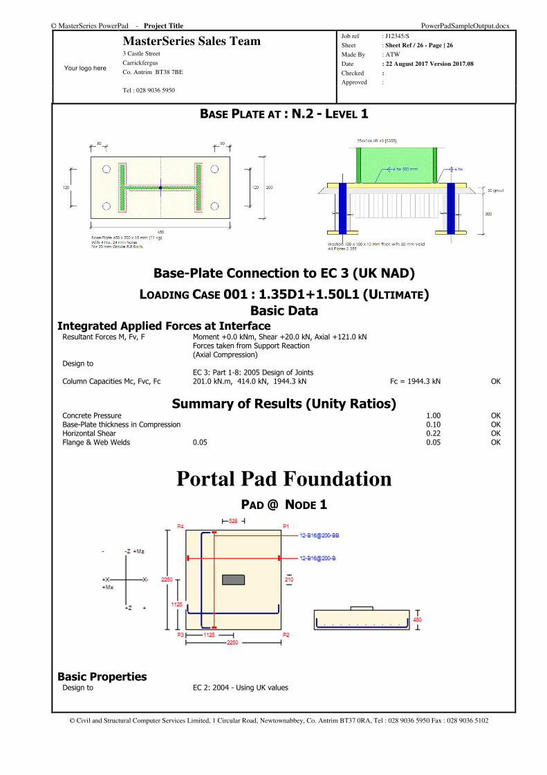
BASE PLATE AT : N.2 - LEVEL 1
Base-Plate Connection to EC 3 (UK NAD)
LOADING CASE 001 : 1.35D1+1.50L1 (ULTIMATE)
Basic Data Integrated Applied Forces at Interface Resultant Forces M, Fv, F Moment +0.0 kNm, Shear +20.0 kN, Axial +121.0 kN Forces taken from Support Reaction (Axial Compression) Design to EC 3: Part 1-8: 2005 Design of Joints Column Capacities Mc, Fvc, Fc 201.0 kN.m, 414.0 kN, 1944.3 kN Fc = 1944.3 kN OK
Summary of Results (Unity Ratios) Concrete Pressure 1.00 OK Base-Plate thickness in Compression 0.10 OK Horizontal Shear 0.22 OK Flange & Web Welds 0.05 0.05 OK
Portal Pad Foundation PAD @ NODE 1
Basic Properties Design to EC 2: 2004 - Using UK values
© MasterSeries PowerPad - Project Title PowerPadSampleOutput.docx
Your logo here
MasterSeries Sales Team 3 Castle Street
Carrickfergus
Co. Antrim BT38 7BE
Job ref : J12345/S
Sheet : Sheet Ref / 27 - Page | 27
Made By : ATW
Date : 22 August 2017 Version 2017.08
Checked :
Approved : Tel : 028 9036 5950
© Civil and Structural Computer Services Limited, 1 Circular Road, Newtownabbey, Co. Antrim BT37 0RA, Tel : 028 9036 5950 Fax : 028 9036 5102
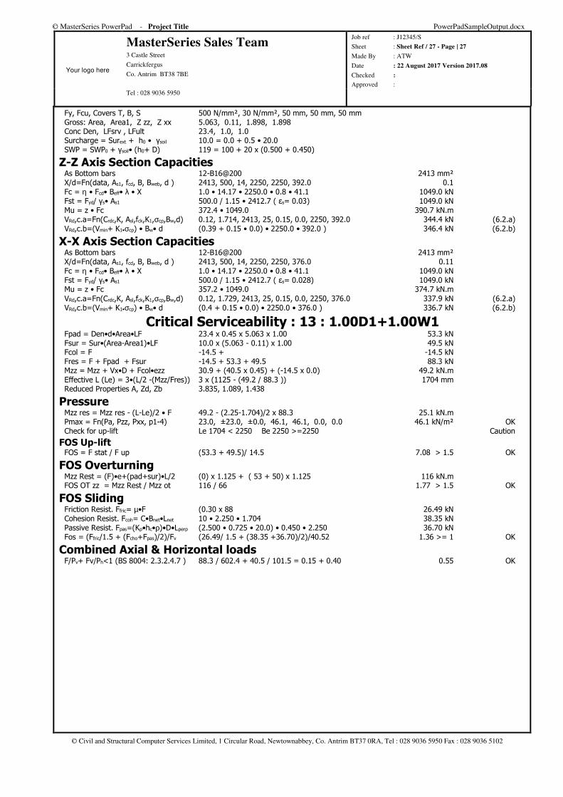
Fy, Fcu, Covers T, B, S 500 N/mm², 30 N/mm², 50 mm, 50 mm, 50 mm Gross: Area, Area1, Z zz, Z xx 5.063, 0.11, 1.898, 1.898 Conc Den, LFsrv , LFult 23.4, 1.0, 1.0 Surcharge = Surext + h0 • γsoil 10.0 = 0.0 + 0.5 • 20.0 SWP = SWP0 + γsoil• (h0+ D) 119 = 100 + 20 x (0.500 + 0.450)
Z-Z Axis Section Capacities As Bottom bars 12-B16@200 2413 mm² X/d=Fn(data, As1, fcd, B, Bweb, d ) 2413, 500, 14, 2250, 2250, 392.0 0.1 Fc = η • Fcd• Beff• λ • X 1.0 • 14.17 • 2250.0 • 0.8 • 41.1 1049.0 kN Fst = Fyd/ γs• As1 500.0 / 1.15 • 2412.7 ( εs= 0.03) 1049.0 kN Mu = z • Fc 372.4 • 1049.0 390.7 kN.m VRd,c.a=Fn(Crdc,K, Asl,fck,K1,σcp,Bw,d) 0.12, 1.714, 2413, 25, 0.15, 0.0, 2250, 392.0 344.4 kN (6.2.a) VRd,c.b=(Vmin+ K1•σcp) • Bw• d (0.39 + 0.15 • 0.0) • 2250.0 • 392.0 ) 346.4 kN (6.2.b)
X-X Axis Section Capacities As Bottom bars 12-B16@200 2413 mm² X/d=Fn(data, As1, fcd, B, Bweb, d ) 2413, 500, 14, 2250, 2250, 376.0 0.11 Fc = η • Fcd• Beff• λ • X 1.0 • 14.17 • 2250.0 • 0.8 • 41.1 1049.0 kN Fst = Fyd/ γs• As1 500.0 / 1.15 • 2412.7 ( εs= 0.028) 1049.0 kN Mu = z • Fc 357.2 • 1049.0 374.7 kN.m VRd,c.a=Fn(Crdc,K, Asl,fck,K1,σcp,Bw,d) 0.12, 1.729, 2413, 25, 0.15, 0.0, 2250, 376.0 337.9 kN (6.2.a) VRd,c.b=(Vmin+ K1•σcp) • Bw• d (0.4 + 0.15 • 0.0) • 2250.0 • 376.0 ) 336.7 kN (6.2.b)
Critical Serviceability : 13 : 1.00D1+1.00W1 Fpad = Den•d•Area•LF 23.4 x 0.45 x 5.063 x 1.00 53.3 kN Fsur = Sur•(Area-Area1)•LF 10.0 x (5.063 - 0.11) x 1.00 49.5 kN Fcol = F -14.5 + -14.5 kN Fres = F + Fpad + Fsur -14.5 + 53.3 + 49.5 88.3 kN Mzz = Mzz + Vx•D + Fcol•ezz 30.9 + (40.5 x 0.45) + (-14.5 x 0.0) 49.2 kN.m Effective L (Le) = 3•(L/2 -(Mzz/Fres)) 3 x (1125 - (49.2 / 88.3 )) 1704 mm Reduced Properties A, Zd, Zb 3.835, 1.089, 1.438
Pressure Mzz res = Mzz res - (L-Le)/2 • F 49.2 - (2.25-1.704)/2 x 88.3 25.1 kN.m Pmax = Fn(Pa, Pzz, Pxx, p1-4) 23.0, ±23.0, ±0.0, 46.1, 46.1, 0.0, 0.0 46.1 kN/m² OK Check for up-lift Le 1704 < 2250 Be 2250 >=2250 Caution
FOS Up-lift FOS = F stat / F up (53.3 + 49.5)/ 14.5 7.08 > 1.5 OK
FOS Overturning Mzz Rest = (F)•e+(pad+sur)•L/2 (0) x 1.125 + ( 53 + 50) x 1.125 116 kN.m FOS OT zz = Mzz Rest / Mzz ot 116 / 66 1.77 > 1.5 OK
FOS Sliding Friction Resist. Ffric= µ•F (0.30 x 88 26.49 kN Cohesion Resist. Fcoh= C•Bnet•Lnet 10 • 2.250 • 1.704 38.35 kN Passive Resist. Fpas=(Kp•hc•ρ)•D•Lperp (2.500 • 0.725 • 20.0) • 0.450 • 2.250 36.70 kN Fos = (Ffric/1.5 + (Fcho+Fpas)/2)/Fv (26.49/ 1.5 + (38.35 +36.70)/2)/40.52 1.36 >= 1 OK
Combined Axial & Horizontal loads F/Pv+ Fv/Ph<1 (BS 8004: 2.3.2.4.7 ) 88.3 / 602.4 + 40.5 / 101.5 = 0.15 + 0.40 0.55 OK
© MasterSeries PowerPad - Project Title PowerPadSampleOutput.docx
Your logo here
MasterSeries Sales Team 3 Castle Street
Carrickfergus
Co. Antrim BT38 7BE
Job ref : J12345/S
Sheet : Sheet Ref / 28 - Page | 28
Made By : ATW
Date : 22 August 2017 Version 2017.08
Checked :
Approved : Tel : 028 9036 5950
© Civil and Structural Computer Services Limited, 1 Circular Road, Newtownabbey, Co. Antrim BT37 0RA, Tel : 028 9036 5950 Fax : 028 9036 5102
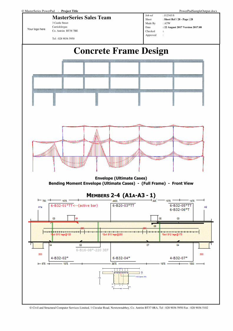
Concrete Frame Design
Envelope (Ultimate Cases)
Bending Moment Envelope (Ultimate Cases) - (Full Frame) - Front View
MEMBERS 2-4 (A1A-A3 - 1)
© MasterSeries PowerPad - Project Title PowerPadSampleOutput.docx
Your logo here
MasterSeries Sales Team 3 Castle Street
Carrickfergus
Co. Antrim BT38 7BE
Job ref : J12345/S
Sheet : Sheet Ref / 29 - Page | 29
Made By : ATW
Date : 22 August 2017 Version 2017.08
Checked :
Approved : Tel : 028 9036 5950
© Civil and Structural Computer Services Limited, 1 Circular Road, Newtownabbey, Co. Antrim BT37 0RA, Tel : 028 9036 5950 Fax : 028 9036 5102
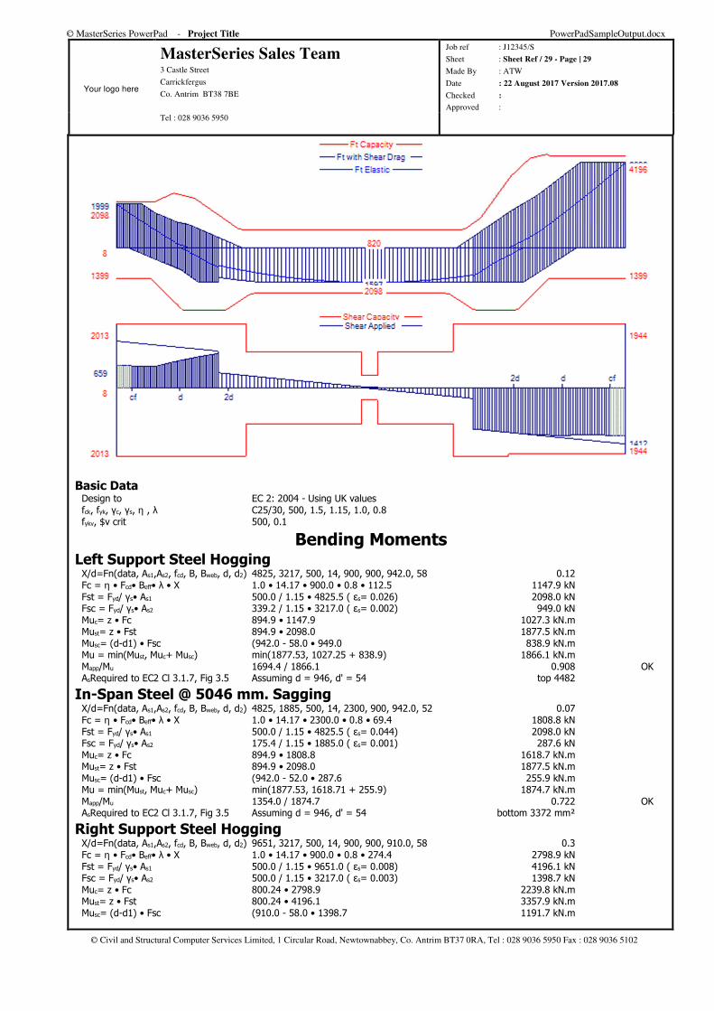
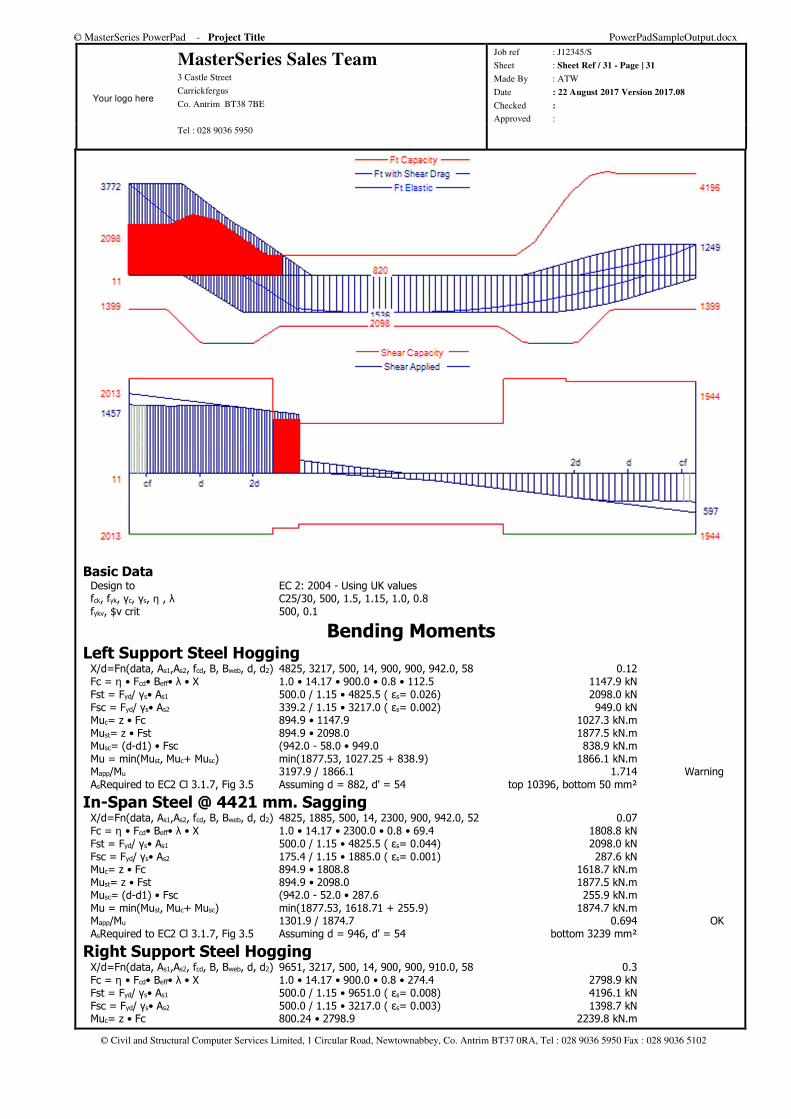
Basic Data Design to EC 2: 2004 - Using UK values fck, fyk, γc, γs, η , λ C25/30, 500, 1.5, 1.15, 1.0, 0.8 fykv, $v crit 500, 0.1
Bending Moments Left Support Steel Hogging X/d=Fn(data, As1,As2, fcd, B, Bweb, d, d2) 4825, 3217, 500, 14, 900, 900, 942.0, 58 0.12 Fc = η • Fcd• Beff• λ • X 1.0 • 14.17 • 900.0 • 0.8 • 112.5 1147.9 kN Fst = Fyd/ γs• As1 500.0 / 1.15 • 4825.5 ( εs= 0.026) 2098.0 kN Fsc = Fyd/ γs• As2 339.2 / 1.15 • 3217.0 ( εs= 0.002) 949.0 kN Muc= z • Fc 894.9 • 1147.9 1027.3 kN.m Must= z • Fst 894.9 • 2098.0 1877.5 kN.m Musc= (d-d1) • Fsc (942.0 - 58.0 • 949.0 838.9 kN.m Mu = min(Must, Muc+ Musc) min(1877.53, 1027.25 + 838.9) 1866.1 kN.m Mapp/Mu 1694.4 / 1866.1 0.908 OK AsRequired to EC2 Cl 3.1.7, Fig 3.5 Assuming d = 946, d' = 54 top 4482
In-Span Steel @ 5046 mm. Sagging X/d=Fn(data, As1,As2, fcd, B, Bweb, d, d2) 4825, 1885, 500, 14, 2300, 900, 942.0, 52 0.07 Fc = η • Fcd• Beff• λ • X 1.0 • 14.17 • 2300.0 • 0.8 • 69.4 1808.8 kN Fst = Fyd/ γs• As1 500.0 / 1.15 • 4825.5 ( εs= 0.044) 2098.0 kN Fsc = Fyd/ γs• As2 175.4 / 1.15 • 1885.0 ( εs= 0.001) 287.6 kN Muc= z • Fc 894.9 • 1808.8 1618.7 kN.m Must= z • Fst 894.9 • 2098.0 1877.5 kN.m Musc= (d-d1) • Fsc (942.0 - 52.0 • 287.6 255.9 kN.m Mu = min(Must, Muc+ Musc) min(1877.53, 1618.71 + 255.9) 1874.7 kN.m Mapp/Mu 1354.0 / 1874.7 0.722 OK AsRequired to EC2 Cl 3.1.7, Fig 3.5 Assuming d = 946, d' = 54 bottom 3372 mm²
Right Support Steel Hogging X/d=Fn(data, As1,As2, fcd, B, Bweb, d, d2) 9651, 3217, 500, 14, 900, 900, 910.0, 58 0.3 Fc = η • Fcd• Beff• λ • X 1.0 • 14.17 • 900.0 • 0.8 • 274.4 2798.9 kN Fst = Fyd/ γs• As1 500.0 / 1.15 • 9651.0 ( εs= 0.008) 4196.1 kN Fsc = Fyd/ γs• As2 500.0 / 1.15 • 3217.0 ( εs= 0.003) 1398.7 kN Muc= z • Fc 800.24 • 2798.9 2239.8 kN.m Must= z • Fst 800.24 • 4196.1 3357.9 kN.m Musc= (d-d1) • Fsc (910.0 - 58.0 • 1398.7 1191.7 kN.m
© MasterSeries PowerPad - Project Title PowerPadSampleOutput.docx
Your logo here
MasterSeries Sales Team 3 Castle Street
Carrickfergus
Co. Antrim BT38 7BE
Job ref : J12345/S
Sheet : Sheet Ref / 30 - Page | 30
Made By : ATW
Date : 22 August 2017 Version 2017.08
Checked :
Approved : Tel : 028 9036 5950
© Civil and Structural Computer Services Limited, 1 Circular Road, Newtownabbey, Co. Antrim BT37 0RA, Tel : 028 9036 5950 Fax : 028 9036 5102
Mu = min(Must, Muc+ Musc) min(3357.86, 2239.79 + 1191.7) 3357.9 kN.m Mapp/Mu 3192.7 / 3357.9 0.951 OK AsRequired to EC2 Cl 3.1.7, Fig 3.5 Assuming d = 882, d' = 54 top 10385, bottom 39 mm²
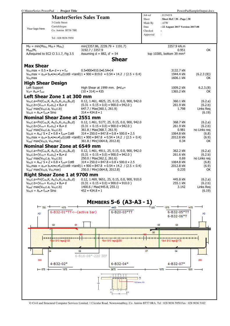
Shear Max Shear VRd,max = 0.5 • Bw• d • v • fcd 0.5•900•910.0•0.54•14 3132.7 kN VRd,max = αcw• bw•z•v1•fcd/(cotθ +tanθ) 1 • 900 • 819.0 • 0.54 • 14.2 / (2.5 + 0.4) 1944.4 kN (6.2.3 (8)) VEd,max 1606.1 kN OK
High Shear Design Left Support High Shear at 1999 mm. β•Ved= 1009.2 kN 6.2.3.(8) Vrd= Asw• fywd (10 • 314) • 435 1365.2 kN OK
Left Shear Zone 1 at 300 mm VRd,c.a=Fn(Crdc,K, Asl,fck,K1,σcp,Bw,d) 0.12, 1.461, 4825, 25, 0.15, 0.0, 900, 942.0 360.1 kN (6.2.a) VRd,c.b=(Vmin+ K1•σcp) • Bw• d (0.31 + 0.15 • 0.0) • 900.0 • 942.0 ) 261.9 kN (6.2.b) Vapp/ max(VRd,c.a, VRd,c.b) 647.7 / Max(360.1, 261.9) 1.798 Links Req VRd,s = Asw• fywd• Sinα 314 • 434.8 • 1 (6.19)
Nominal Shear Zone at 2551 mm VRd,c.a=Fn(Crdc,K, Asl,fck,K1,σcp,Bw,d) 0.12, 1.461, 5177, 25, 0.15, 0.0, 900, 942.0 368.7 kN (6.2.a) VRd,c.b=(Vmin+ K1•σcp) • Bw• d (0.31 + 0.15 • 0.0) • 900.0 • 942.0 ) 261.9 kN (6.2.b) Vapp/ max(VRd,c.a, VRd,c.b) 361.8 / Max(368.7, 261.9) 0.981 no Links req VRd,s = Asw/ S • Z • 0.8 • fywk• Cotθ 314 • 250.0 • 847.8 • 0.8 • 500.0 • 2.5 1064.8 kN (6.8) VRd,max = αcw• bw•z•v1•fcd/(cotθ +tanθ) 1 • 900 • 847.8 • 0.54 • 14.2 / (2.5 + 0.4) 2012.8 kN (6.9) Vapp/ max(VRd,s, VRd,max) 361.8 / Min(1064.8, 2012.8) 0.34 OK
Nominal Shear Zone at 6549 mm VRd,c.a=Fn(Crdc,K, Asl,fck,K1,σcp,Bw,d) 0.12, 1.461, 4911, 25, 0.15, 0.0, 900, 942.0 362.2 kN (6.2.a) VRd,c.b=(Vmin+ K1•σcp) • Bw• d (0.31 + 0.15 • 0.0) • 900.0 • 942.0 ) 261.6 kN (6.2.b) Vapp/ max(VRd,c.a, VRd,c.b) 250.0 / Max(362.2, 261.6) 0.69 no Links req VRd,s = Asw/ S • Z • 0.8 • fywk• Cotθ 314 • 250.0 • 847.8 • 0.8 • 500.0 • 2.5 1064.8 kN (6.8) VRd,max = αcw• bw•z•v1•fcd/(cotθ +tanθ) 1 • 900 • 847.8 • 0.54 • 14.2 / (2.5 + 0.4) 2012.8 kN (6.9) Vapp/ max(VRd,s, VRd,max) 250.0 / Min(1064.8, 2012.8) 0.235 OK
Right Shear Zone 1 at 9700 mm VRd,c.a=Fn(Crdc,K, Asl,fck,K1,σcp,Bw,d) 0.12, 1.469, 9651, 25, 0.15, 0.0, 900, 910.0 445.8 kN (6.2.a) VRd,c.b=(Vmin+ K1•σcp) • Bw• d (0.31 + 0.15 • 0.0) • 900.0 • 910.0 ) 255.1 kN (6.2.b) Vapp/ max(VRd,c.a, VRd,c.b) 1400.6 / Max(445.8, 255.1) 3.142 Links Req VRd,s = Asw• fywd• Sinα 452 • 434.8 • 1 (6.19)
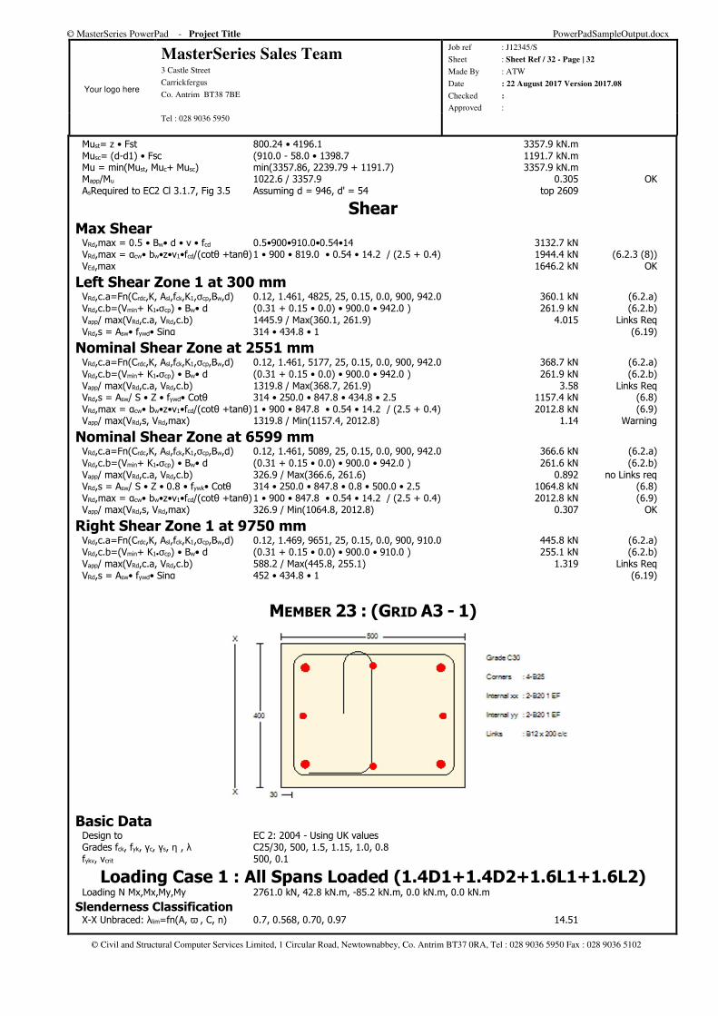
MEMBERS 5-6 (A3-A3 - 1)
© MasterSeries PowerPad - Project Title PowerPadSampleOutput.docx
Your logo here
MasterSeries Sales Team 3 Castle Street
Carrickfergus
Co. Antrim BT38 7BE
Job ref : J12345/S
Sheet : Sheet Ref / 31 - Page | 31
Made By : ATW
Date : 22 August 2017 Version 2017.08
Checked :
Approved : Tel : 028 9036 5950
© Civil and Structural Computer Services Limited, 1 Circular Road, Newtownabbey, Co. Antrim BT37 0RA, Tel : 028 9036 5950 Fax : 028 9036 5102
Basic Data Design to EC 2: 2004 - Using UK values fck, fyk, γc, γs, η , λ C25/30, 500, 1.5, 1.15, 1.0, 0.8 fykv, $v crit 500, 0.1
Bending Moments Left Support Steel Hogging X/d=Fn(data, As1,As2, fcd, B, Bweb, d, d2) 4825, 3217, 500, 14, 900, 900, 942.0, 58 0.12 Fc = η • Fcd• Beff• λ • X 1.0 • 14.17 • 900.0 • 0.8 • 112.5 1147.9 kN Fst = Fyd/ γs• As1 500.0 / 1.15 • 4825.5 ( εs= 0.026) 2098.0 kN Fsc = Fyd/ γs• As2 339.2 / 1.15 • 3217.0 ( εs= 0.002) 949.0 kN Muc= z • Fc 894.9 • 1147.9 1027.3 kN.m Must= z • Fst 894.9 • 2098.0 1877.5 kN.m Musc= (d-d1) • Fsc (942.0 - 58.0 • 949.0 838.9 kN.m Mu = min(Must, Muc+ Musc) min(1877.53, 1027.25 + 838.9) 1866.1 kN.m Mapp/Mu 3197.9 / 1866.1 1.714 Warning AsRequired to EC2 Cl 3.1.7, Fig 3.5 Assuming d = 882, d' = 54 top 10396, bottom 50 mm²
In-Span Steel @ 4421 mm. Sagging X/d=Fn(data, As1,As2, fcd, B, Bweb, d, d2) 4825, 1885, 500, 14, 2300, 900, 942.0, 52 0.07 Fc = η • Fcd• Beff• λ • X 1.0 • 14.17 • 2300.0 • 0.8 • 69.4 1808.8 kN Fst = Fyd/ γs• As1 500.0 / 1.15 • 4825.5 ( εs= 0.044) 2098.0 kN Fsc = Fyd/ γs• As2 175.4 / 1.15 • 1885.0 ( εs= 0.001) 287.6 kN Muc= z • Fc 894.9 • 1808.8 1618.7 kN.m Must= z • Fst 894.9 • 2098.0 1877.5 kN.m Musc= (d-d1) • Fsc (942.0 - 52.0 • 287.6 255.9 kN.m Mu = min(Must, Muc+ Musc) min(1877.53, 1618.71 + 255.9) 1874.7 kN.m Mapp/Mu 1301.9 / 1874.7 0.694 OK AsRequired to EC2 Cl 3.1.7, Fig 3.5 Assuming d = 946, d' = 54 bottom 3239 mm²
Right Support Steel Hogging X/d=Fn(data, As1,As2, fcd, B, Bweb, d, d2) 9651, 3217, 500, 14, 900, 900, 910.0, 58 0.3 Fc = η • Fcd• Beff• λ • X 1.0 • 14.17 • 900.0 • 0.8 • 274.4 2798.9 kN Fst = Fyd/ γs• As1 500.0 / 1.15 • 9651.0 ( εs= 0.008) 4196.1 kN Fsc = Fyd/ γs• As2 500.0 / 1.15 • 3217.0 ( εs= 0.003) 1398.7 kN Muc= z • Fc 800.24 • 2798.9 2239.8 kN.m
© MasterSeries PowerPad - Project Title PowerPadSampleOutput.docx
Your logo here
MasterSeries Sales Team 3 Castle Street
Carrickfergus
Co. Antrim BT38 7BE
Job ref : J12345/S
Sheet : Sheet Ref / 32 - Page | 32
Made By : ATW
Date : 22 August 2017 Version 2017.08
Checked :
Approved : Tel : 028 9036 5950
© Civil and Structural Computer Services Limited, 1 Circular Road, Newtownabbey, Co. Antrim BT37 0RA, Tel : 028 9036 5950 Fax : 028 9036 5102
Must= z • Fst 800.24 • 4196.1 3357.9 kN.m Musc= (d-d1) • Fsc (910.0 - 58.0 • 1398.7 1191.7 kN.m Mu = min(Must, Muc+ Musc) min(3357.86, 2239.79 + 1191.7) 3357.9 kN.m Mapp/Mu 1022.6 / 3357.9 0.305 OK AsRequired to EC2 Cl 3.1.7, Fig 3.5 Assuming d = 946, d' = 54 top 2609
Shear Max Shear VRd,max = 0.5 • Bw• d • v • fcd 0.5•900•910.0•0.54•14 3132.7 kN VRd,max = αcw• bw•z•v1•fcd/(cotθ +tanθ) 1 • 900 • 819.0 • 0.54 • 14.2 / (2.5 + 0.4) 1944.4 kN (6.2.3 (8)) VEd,max 1646.2 kN OK
Left Shear Zone 1 at 300 mm VRd,c.a=Fn(Crdc,K, Asl,fck,K1,σcp,Bw,d) 0.12, 1.461, 4825, 25, 0.15, 0.0, 900, 942.0 360.1 kN (6.2.a) VRd,c.b=(Vmin+ K1•σcp) • Bw• d (0.31 + 0.15 • 0.0) • 900.0 • 942.0 ) 261.9 kN (6.2.b) Vapp/ max(VRd,c.a, VRd,c.b) 1445.9 / Max(360.1, 261.9) 4.015 Links Req VRd,s = Asw• fywd• Sinα 314 • 434.8 • 1 (6.19)
Nominal Shear Zone at 2551 mm VRd,c.a=Fn(Crdc,K, Asl,fck,K1,σcp,Bw,d) 0.12, 1.461, 5177, 25, 0.15, 0.0, 900, 942.0 368.7 kN (6.2.a) VRd,c.b=(Vmin+ K1•σcp) • Bw• d (0.31 + 0.15 • 0.0) • 900.0 • 942.0 ) 261.9 kN (6.2.b) Vapp/ max(VRd,c.a, VRd,c.b) 1319.8 / Max(368.7, 261.9) 3.58 Links Req VRd,s = Asw/ S • Z • fywd• Cotθ 314 • 250.0 • 847.8 • 434.8 • 2.5 1157.4 kN (6.8) VRd,max = αcw• bw•z•v1•fcd/(cotθ +tanθ) 1 • 900 • 847.8 • 0.54 • 14.2 / (2.5 + 0.4) 2012.8 kN (6.9) Vapp/ max(VRd,s, VRd,max) 1319.8 / Min(1157.4, 2012.8) 1.14 Warning
Nominal Shear Zone at 6599 mm VRd,c.a=Fn(Crdc,K, Asl,fck,K1,σcp,Bw,d) 0.12, 1.461, 5089, 25, 0.15, 0.0, 900, 942.0 366.6 kN (6.2.a) VRd,c.b=(Vmin+ K1•σcp) • Bw• d (0.31 + 0.15 • 0.0) • 900.0 • 942.0 ) 261.6 kN (6.2.b) Vapp/ max(VRd,c.a, VRd,c.b) 326.9 / Max(366.6, 261.6) 0.892 no Links req VRd,s = Asw/ S • Z • 0.8 • fywk• Cotθ 314 • 250.0 • 847.8 • 0.8 • 500.0 • 2.5 1064.8 kN (6.8) VRd,max = αcw• bw•z•v1•fcd/(cotθ +tanθ) 1 • 900 • 847.8 • 0.54 • 14.2 / (2.5 + 0.4) 2012.8 kN (6.9) Vapp/ max(VRd,s, VRd,max) 326.9 / Min(1064.8, 2012.8) 0.307 OK
Right Shear Zone 1 at 9750 mm VRd,c.a=Fn(Crdc,K, Asl,fck,K1,σcp,Bw,d) 0.12, 1.469, 9651, 25, 0.15, 0.0, 900, 910.0 445.8 kN (6.2.a) VRd,c.b=(Vmin+ K1•σcp) • Bw• d (0.31 + 0.15 • 0.0) • 900.0 • 910.0 ) 255.1 kN (6.2.b) Vapp/ max(VRd,c.a, VRd,c.b) 588.2 / Max(445.8, 255.1) 1.319 Links Req VRd,s = Asw• fywd• Sinα 452 • 434.8 • 1 (6.19)
MEMBER 23 : (GRID A3 - 1)
Basic Data Design to EC 2: 2004 - Using UK values Grades fck, fyk, γc, γs, η , λ C25/30, 500, 1.5, 1.15, 1.0, 0.8 fykv, vcrit 500, 0.1
Loading Case 1 : All Spans Loaded (1.4D1+1.4D2+1.6L1+1.6L2) Loading N Mx,Mx,My,My 2761.0 kN, 42.8 kN.m, -85.2 kN.m, 0.0 kN.m, 0.0 kN.m
Slenderness Classification X-X Unbraced: λlim=fn(A, ω , C, n) 0.7, 0.568, 0.70, 0.97 14.51
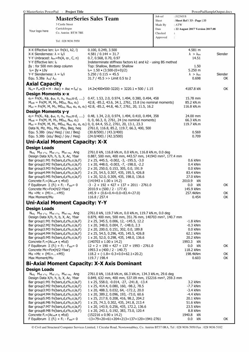
© MasterSeries PowerPad - Project Title PowerPadSampleOutput.docx
Your logo here
MasterSeries Sales Team 3 Castle Street
Carrickfergus
Co. Antrim BT38 7BE
Job ref : J12345/S
Sheet : Sheet Ref / 33 - Page | 33
Made By : ATW
Date : 22 August 2017 Version 2017.08
Checked :
Approved : Tel : 028 9036 5950
© Civil and Structural Computer Services Limited, 1 Circular Road, Newtownabbey, Co. Antrim BT37 0RA, Tel : 028 9036 5950 Fax : 028 9036 5102
X-X Effective len: l0= fn(k1, k2, l) 0.100, 0.249, 3.500 4.581 m X-X Slenderness: λ = l0/i 4.581 / 0.144 = 31.7 λ > λlim Slender Y-Y Unbraced: λlim=fn(A, ω , C, n) 0.7, 0.568, 0.70, 0.97 14.51 Y-Y Effective len: l0 Indeterminate stiffness factors k1 and k2 - using BS method βy : for 500 mm deep column Top: Shallow, Bottom: Shallow 1.50 l0= βy • L0y l0= 1.50 • (3.500-(0+0)/2) 5.250 m Y-Y Slenderness: λ = l0/i 5.250 / 0.115 = 45.5 λ > λlim Slender Equ. 5.38a λxx/ λyy 31.7 / 45.5 >> Limit 0.5 to 2 0.698 OK
Axial Capacity Nuz= Fav•(B • H - Asc) + Asc • fyk/ γs 14.2•(400•500-3220) + 3220.1 • 500 / 1.15 4187.8 kN OK
Design Moments x-x e2= Fn(Kr, Kϕ, ϕeff, n, nu, nbal,ω d, ....) 0.47, 1.53, 2.0, 0.974, 1.494, 0.380, 0.494, 458 15.78 mm Med0 = Fn(M, M, M2, M0ed, Ned, e2) 42.8, -85.2, 43.6, 34.1, 2761, 15.8 (no nominal moments) 85.2 kN.m Med = Fn(M, M, M2, M0ed, Ned, e0, ei, e2) 42.8, -85.2, 44.8, 46.7, 2761, 20, 11.5, 16.2 116.8 kN.m
Design Moments y-y e2= Fn(Kr, Kϕ, ϕeff, n, nu, nbal,ω d, ....) 0.48, 1.34, 2.0, 0.974, 1.494, 0.410, 0.494, 358 24.00 mm Med0 = Fn(M, M, M2, M0ed, Ned, e2) 0, 0, 66.3, 0, 2761, 24 (no nominal moments) 66.3 kN.m Med = Fn(M, M, M2, M0ed, Ned, e0, ei, e2) 0, 0, 64.4, 55.2, 2761, 20, 13.1, 23.3 119.7 kN.m Data N, Mz, Mz0, My, My0, Beq, heq 2761.0, 116.8, 85.2, 119.7, 66.3, 400, 500 Equ. 5.38b (ey0/ Heq) / (ez / Beq) (30.8/500) / (43.3/400) 0.569 Equ. 5.38b (ez0/ Beq) / (ey / Heq) (24.0/400) / (42.3/500) 0.709
Uni-Axial Moment Capacity: X-X Design Loads Ned, Med x-x, Med y-y, Med res, Ang 2761.0 kN, 116.8 kN.m, 0.0 kN.m, 116.8 kN.m, 0.0 deg Design Data X/h, h, b, X, Ac, Ybar 0.887, 500 mm, 400 mm, 443.57 mm, 141943 mm², 177.4 mm Bar group1:M1 fn(bars,d,ε%,σ,la,F) 2 x 25, 445.5, -0.002, -3, -195.5, -3.0 0.6 kNm Bar group2:M2 fn(bars,d,ε%,σ,la,F) 1 x 20, 448.0, -0.003, -7, -198.0, -2.2 0.4 kNm Bar group3:M3 fn(bars,d,ε%,σ,la,F) 2 x 20, 250.0, 0.153, 305, 0.0, 191.9 0.0 kNm Bar group4:M4 fn(bars,d,ε%,σ,la,F) 2 x 25, 54.5, 0.307, 435, 195.5, 426.8 83.4 kNm Bar group5:M5 fn(bars,d,ε%,σ,la,F) 1 x 20, 52.0, 0.309, 435, 198.0, 136.6 27.0 kNm Concrete Fc=(Acnet• η •fcd) (141943 x 1.00 x 14.2) 2010.9 kN F Equlibrum Σ (Ft) + FC - Fapp= 0 -3 - 2 + 192 + 427 + 137 + 2011 - 2761.0 0.0 kN OK Concrete Mc=Fc•(H/2-Ybar) 2010.9 x (500 / 2 - 177.4) 145.9 kNm Mu =Mc + (M1+...+M5) 145.9 + (0.6+0.4+0.0+83.4+27.0) 257.4kNm OK Max Moment/Mu 116.8 / 257.4 0.454 OK
Uni-Axial Moment Capacity: Y-Y Design Loads Ned, Med y-y, Med x-x, Med res, Ang 2761.0 kN, 119.7 kN.m, 0.0 kN.m, 119.7 kN.m, 0.0 deg Design Data X/h, h, b, X, Ac, Ybar 0.879, 400 mm, 500 mm, 351.76 mm, 140703 mm², 140.7 mm Bar group1:M1 fn(bars,d,ε%,σ,la,F) 2 x 25, 345.5, 0.006, 12, -145.5, 12.2 -1.8 kNm Bar group2:M2 fn(bars,d,ε%,σ,la,F) 1 x 20, 348.0, 0.004, 7, -148.0, 2.3 -0.3 kNm Bar group3:M3 fn(bars,d,ε%,σ,la,F) 2 x 20, 200.0, 0.151, 302, 0.0, 189.8 0.0 kNm Bar group4:M4 fn(bars,d,ε%,σ,la,F) 2 x 25, 54.5, 0.296, 435, 145.5, 426.8 62.1 kNm Bar group5:M5 fn(bars,d,ε%,σ,la,F) 1 x 20, 52.0, 0.298, 435, 148.0, 136.6 20.2 kNm Concrete Fc=(Acnet• η •fcd) (140703 x 1.00 x 14.2) 1993.3 kN F Equlibrum Σ (Ft) + FC - Fapp= 0 12 + 2 + 190 + 427 + 137 + 1993 - 2761.0 0.0 kN OK Concrete Mc=Fc•(H/2-Ybar) 1993.3 x (400 / 2 - 140.7) 118.2 kNm Mu =Mc + (M1+...+M5) 118.2 + (-1.8+-0.3+0.0+62.1+20.2) 198.4kNm OK Max Moment/Mu 119.7 / 198.4 0.603 OK
Bi-Axial Moment Capacity: X-X Axis Dominant Design Loads Ned, Med x-x, Med y-y, Med res, Ang 2761.0 kN, 116.8 kN.m, 66.3 kN.m, 134.3 kN.m, 29.6 deg Design Data X/h, h, b, X, Ac, Ybar 0.849, 632 mm, 400 mm, 537.09 mm, 152216 mm², 259.3 mm Bar group1:M1 fn(bars,d,ε%,σ,la,F) 1 x 25, 558.0, -0.014, -27, -241.8, -13.4 3.2 kNm Bar group2:M2 fn(bars,d,ε%,σ,la,F) 1 x 25, 414.4, 0.080, 160, -98.2, 78.5 -7.7 kNm Bar group3:M3 fn(bars,d,ε%,σ,la,F) 1 x 20, 488.3, 0.032, 64, -172.2, 20.0 -3.4 kNm Bar group4:M4 fn(bars,d,ε%,σ,la,F) 1 x 20, 389.2, 0.096, 193, -73.0, 60.6 -4.4 kNm Bar group5:M5 fn(bars,d,ε%,σ,la,F) 1 x 25, 217.9, 0.208, 416, 98.2, 204.2 20.1 kNm Bar group6:M6 fn(bars,d,ε%,σ,la,F) 1 x 25, 74.3, 0.302, 435, 241.8, 213.4 51.6 kNm Bar group7:M7 fn(bars,d,ε%,σ,la,F) 1 x 20, 143.9, 0.256, 435, 172.2, 136.6 23.5 kNm Bar group8:M8 fn(bars,d,ε%,σ,la,F) 1 x 20, 243.1, 0.192, 383, 73.0, 120.4 8.8 kNm Concrete Fc=(Acnet• η •fcd) (152216 x 0.90 x 14.2) 1940.8 kN F Equlibrum Σ (Ft) + FC - Fapp= 0 -13+79+20+61+204+213+137+120+1941-2761 0.0 kN OK
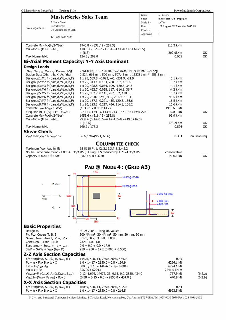
© MasterSeries PowerPad - Project Title PowerPadSampleOutput.docx
Your logo here
MasterSeries Sales Team 3 Castle Street
Carrickfergus
Co. Antrim BT38 7BE
Job ref : J12345/S
Sheet : Sheet Ref / 34 - Page | 34
Made By : ATW
Date : 22 August 2017 Version 2017.08
Checked :
Approved : Tel : 028 9036 5950
© Civil and Structural Computer Services Limited, 1 Circular Road, Newtownabbey, Co. Antrim BT37 0RA, Tel : 028 9036 5950 Fax : 028 9036 5102
Concrete Mc=Fc•(H/2-Ybar) 1940.8 x (632 / 2 - 259.3) 110.3 kNm Mu =Mc + (M1+...+M8) 110.3 + (3.2+-7.7+-3.4+-4.4+20.1+51.6+23.5) + (8.8) 202.0kNm OK Max Moment/Mu 134.3 / 202.0 0.665 OK
Bi-Axial Moment Capacity: Y-Y Axis Dominant Design Loads Ned, Med y-y, Med x-x, Med res, Ang 2761.0 kN, 119.7 kN.m, 85.2 kN.m, 146.9 kN.m, 35.4 deg Design Data X/h, h, b, X, Ac, Ybar 0.824, 616 mm, 500 mm, 507.42 mm, 153381 mm², 256.8 mm Bar group1:M1 fn(bars,d,ε%,σ,la,F) 1 x 25, 539.8, -0.022, -45, -231.9, -21.9 5.1 kNm Bar group2:M2 fn(bars,d,ε%,σ,la,F) 1 x 25, 313.1, 0.134, 268, -5.2, 131.6 -0.7 kNm Bar group3:M3 fn(bars,d,ε%,σ,la,F) 1 x 20, 428.5, 0.054, 109, -120.6, 34.2 -4.1 kNm Bar group4:M4 fn(bars,d,ε%,σ,la,F) 1 x 20, 422.7, 0.058, 117, -114.8, 36.7 -4.2 kNm Bar group5:M5 fn(bars,d,ε%,σ,la,F) 1 x 25, 302.7, 0.141, 282, 5.2, 138.6 0.7 kNm Bar group6:M6 fn(bars,d,ε%,σ,la,F) 1 x 25, 76.0, 0.298, 435, 231.9, 213.4 49.5 kNm Bar group7:M7 fn(bars,d,ε%,σ,la,F) 1 x 20, 187.3, 0.221, 435, 120.6, 136.6 16.5 kNm Bar group8:M8 fn(bars,d,ε%,σ,la,F) 1 x 20, 193.1, 0.217, 434, 114.8, 136.2 15.6 kNm Concrete Fc=(Acnet• η •fcd) (153381 x 0.90 x 14.2) 1955.6 kN F Equlibrum Σ (Ft) + FC - Fapp= 0 -22+132+34+37+139+213+137+136+1956-2761 0.0 kN OK Concrete Mc=Fc•(H/2-Ybar) 1955.6 x (616 / 2 - 256.8) 99.9 kNm Mu =Mc + (M1+...+M8) 99.9 + (5.1+-0.7+-4.1+-4.2+0.7+49.5+16.5) + (15.6) 178.2kNm OK Max Moment/Mu 146.9 / 178.2 0.824 OK
Shear Check Vapp/ max(VRd,c.a, VRd,c.b) 36.6 / Max(95.1, 68.6) 0.384 no Links req
COLUMN TIE CHECK Maximum floor load in lift BS 8110 Pt 1: CL 3.12.3.7 & 2.4.3.2 No Tie Force case found (1.05D+0.35/1.05L). Using ULS reduced by 1.28=1.35/1.05 conservative Capacity = 0.87 • fy• Asc 0.87 • 500 • 3220 1400.1 kN OK
PAD @ NODE 4 : (GRID A3)
Basic Properties Design to EC 2: 2004 - Using UK values Fy, Fcu, Covers T, B, S 500 N/mm², 30 N/mm², 50 mm, 50 mm, 50 mm Gross: Area, Area1, Z zz, Z xx 8.123, 0.2, 3.858, 3.858 Conc Den, LFsrv , LFult 23.4, 1.0, 1.0 Surcharge = Surext + h0 • γsoil 0.0 = 0.0 + 0.0 • 17.0 SWP = SWP0 + γsoil• (h0+ D) 258 = 250 + 17 x (0.000 + 0.500)
Z-Z Axis Section Capacities X/d=Fn(data, As1, fcd, B, Bweb, d ) 14476, 500, 14, 2850, 2850, 434.0 0.45 Fc = η • Fcd• Beff• λ • X 1.0 • 14.17 • 2850.0 • 0.8 • 194.9 6294.1 kN Fst = Fyd/ γs• As1 500.0 / 1.15 • 14476.5 ( εs= 0.004) 6294.1 kN Mu = z • Fc 356.05 • 6294.1 2241.0 kN.m VRd,c.a=Fn(Crdc,K, Asl,fck,K1,σcp,Bw,d) 0.12, 1.679, 14476, 25, 0.15, 0.0, 2850, 434.0 767.9 kN (6.2.a) VRd,c.b=(Vmin+ K1•σcp) • Bw• d (0.38 + 0.15 • 0.0) • 2850.0 • 434.0 ) 470.9 kN (6.2.b)
X-X Axis Section Capacities X/d=Fn(data, As1, fcd, B, Bweb, d ) 16085, 500, 14, 2850, 2850, 402.0 0.54 Fc = η • Fcd• Beff• λ • X 1.0 • 14.17 • 2850.0 • 0.8 • 216.5 6993.5 kN
© MasterSeries PowerPad - Project Title PowerPadSampleOutput.docx
Your logo here
MasterSeries Sales Team 3 Castle Street
Carrickfergus
Co. Antrim BT38 7BE
Job ref : J12345/S
Sheet : Sheet Ref / 35 - Page | 35
Made By : ATW
Date : 22 August 2017 Version 2017.08
Checked :
Approved : Tel : 028 9036 5950
© Civil and Structural Computer Services Limited, 1 Circular Road, Newtownabbey, Co. Antrim BT37 0RA, Tel : 028 9036 5950 Fax : 028 9036 5102
Fst = Fyd/ γs• As1 500.0 / 1.15 • 16085.0 ( εs= 0.003) 6993.5 kN Mu = z • Fc 315.39 • 6993.5 2205.7 kN.m VRd,c.a=Fn(Crdc,K, Asl,fck,K1,σcp,Bw,d) 0.12, 1.705, 16085, 25, 0.15, 0.0, 2850, 402.0 767.6 kN (6.2.a) VRd,c.b=(Vmin+ K1•σcp) • Bw• d (0.39 + 0.15 • 0.0) • 2850.0 • 402.0 ) 446.5 kN (6.2.b)
Critical Serviceability : 4 : All Spans Loaded (D1+D2+L1+L2) Pressure Pmax = Fn(Pa, Pzz, Pxx, p1-4) 243.2, ±11.0, ±0.0, 254.2, 254.2, 232.2, 232.2 254.2 kN/m² OK Check for up-lift Le 2850 >=2850 Be 2850 >=2850 OK
FOS Overturning FOS OT zz = Mzz Rest / Mzz ot 2815 / 42 66.43 > 1.5 OK
FOS Sliding FOS Sliding = 0.30 • F / Fv (0.30 x 1975) / 25 23.36 > 1.5 OK
Combined Axial & Horizontal loads F/Pv+ Fv/Ph<1 (BS 8004: 2.3.2.4.7 ) 1975.5 / 2095.6 + 25.4 / 592.6 = 0.94 + 0.04 0.99 OK
Critical Ultimate : 1 : All Spans Loaded (1.4D1+1.4D2+1.6L1+1.6L2) Pressure eccx= Mzz/F 61.1 / 2856.1 about centre of base 21.4 mm eccz= Mxx/F 0.0 / 2856.1 about centre of base 0.0 mm Area = Lxeff • Lzeff 2807.2 • 2850.0 8.0 m² Pressure = F / Area 2856.1 / 8.0 357.0 kN/m² Pressures P1to P9 P4=0.0 , P8=357.0 , P1=357.0 P7=0.0 , P9=357.0 , P5=357.0 P3=0.0 , P6=357.0 , P2=357.0 357.0 kN/m² Max
Moments and Shears Static load reduction w=(Sur + Den•D)•L
(0.0 + 23.4 x 0.5) x 1.00 11.7kN/m² Check for up-lift (ULS)
FOS Overturning FOS OT zz = Mzz Rest / Mzz ot 4070 / 61 66.66 > 1.0 OK
FOS Sliding FOS Sliding = 0.30 • F / Fv (0.30 x 2856) / 37 23.44 > 1.0 OK
Moments at Column Face X-X Moment LowerM - w•B•la²/2 751.9 - 11.7 • 2.9 • 1.2² / 2 726.9 kN.m OK X-X Moment UpperM - w•B•la²/2 751.9 - 11.7 • 2.9 • 1.2² / 2 726.9 kN.m OK Z-Z Moment Left UpperM - w•B•la²/2 652.1 - 11.7 • 2.9 • 1.2² / 2 629.1 kN.m OK Z-Z Moment Right UpperM - w•B•la²/2 702.3 - 11.7 • 2.9 • 1.2² / 2 679.3 kN.m OK
'Beam' Shear at d from Column Face X-X Lower Vd- w•B•la 792.7 - 11.7 • 2.9 • 0.8 766.3 kN OK X-X Upper Vd- w•B•la 792.7 - 11.7 • 2.9 • 0.8 766.3 kN OK Z-Z Left Vd- w•B•la 742.9 - 11.7 • 2.9 • 0.8 717.2 kN OK Z-Z Right Vd- w•B•la 786.4 - 11.7 • 2.9 • 0.8 760.7 kN OK
Punching Shear at Column Head vRd,max (stress) 3.825 N/mm² Zone 0: Column Head Inner Load Fin= Area • (Pmax- Pstatic) 0.2 • (356.98 - 11.7) 69.1 kN Shear stress (Fnet- Fin) / Perim / d (2761.04 - 69.056) / 1800 / 418 3.578 N/mm² OK
Punching Shear at 1 d vRd,c (stress) • 2 av = d thus Β = av/2d >>> x 2 (cl 6.2.2.6) 1.291 N/mm² Zone 1: Full Punching Inner Load Fin= Area • (Pmax- Pstatic) 1.487 • (356.98 - 11.7) 513.5 kN Shear stress (Fnet- Fin) / Perim / d (2761.04 - 513.539) / 4426.371 / 418 1.215 N/mm² OK Zone 2: Left Side Free (2761.04 - 846.047) / 5063.186 / 418 0.905 N/mm² OK Zone 3: Right Side Free (2761.04 - 864.912) / 5063.186 / 418 0.896 N/mm² OK Zone 4: Top Side Free (2761.04 - 914.114) / 5063.186 / 418 0.873 N/mm² OK Zone 5: Bottom Side Free (2761.04 - 914.114) / 5063.186 / 418 0.873 N/mm² OK Zone 6: Left & Bottom Sides Free (2761.04 - 1431.081) / 3956.593 / 418 0.804 N/mm² OK Zone 7: Left & Top Sides Free (2761.04 - 1431.081) / 3956.593 / 418 0.804 N/mm² OK Zone 8: Right & Top Sides Free (2761.04 - 1462.262) / 3956.593 / 418 0.785 N/mm² OK Zone 9: Right & Bottom Sides Free (2761.04 - 1462.262) / 3956.593 / 418 0.785 N/mm² OK
© MasterSeries PowerPad - Project Title PowerPadSampleOutput.docx
Your logo here
MasterSeries Sales Team 3 Castle Street
Carrickfergus
Co. Antrim BT38 7BE
Job ref : J12345/S
Sheet : Sheet Ref / 36 - Page | 36
Made By : ATW
Date : 22 August 2017 Version 2017.08
Checked :
Approved : Tel : 028 9036 5950
© Civil and Structural Computer Services Limited, 1 Circular Road, Newtownabbey, Co. Antrim BT37 0RA, Tel : 028 9036 5950 Fax : 028 9036 5102
Punching Shear at 2 d vRd,c (stress) av = 2d Β = 1 (cl 6.2.2.6) 0.645 N/mm² Zone 1: Full Punching Inner Load Fin= Area • (Pmax- Pstatic) 3.844 • (356.98 - 11.7) 1327.4 kN Shear stress (Fnet- Fin) / Perim / d (2761.04 - 1327.411) / 7052.743 / 418 0.486 N/mm² OK Zone 2: Left Side Free (2761.04 - 1651.556) / 6376.371 / 418 0.416 N/mm² OK Zone 3: Right Side Free (2761.04 - 1683.18) / 6376.371 / 418 0.404 N/mm² OK Zone 4: Top Side Free (2761.04 - 1732.382) / 6376.371 / 418 0.386 N/mm² OK Zone 5: Bottom Side Free (2761.04 - 1732.382) / 6376.371 / 418 0.386 N/mm² OK Zone 6: Left & Bottom Sides Free (2761.04 - 2039.502) / 4613.186 / 418 0.374 N/mm² OK Zone 7: Left & Top Sides Free (2761.04 - 2039.502) / 4613.186 / 418 0.374 N/mm² OK Zone 8: Right & Top Sides Free (2761.04 - 2077.063) / 4613.186 / 418 0.355 N/mm² OK Zone 9: Right & Bottom Sides Free (2761.04 - 2077.063) / 4613.186 / 418 0.355 N/mm² OK
Bar Schedule Bar Schedule
Member Bar mark
Type and size
No. of
mbrs
No.of bars in each
Total no.
Length of each bar + mm
Shape code
A* mm B* mm C* mm D* mm E/R* mm
R e v
Beams A1-A3 - 1 01 B20 1 6 6 5425 11 5020 460 02 B12 1 6 6 5075 11 4620 460 03 B16 1 6 6 4400 00 4400 04 B10 1 89 89 3700 51 835 935 130 130 05 B10 1 89 89 2600 51 275 935 130 130 06 B32 1 6 6 3550 00 3550 07 B32 1 4 4 1775 00 1775 08 B20 1 6 6 6000 00 6000 09 B32 1 6 6 6150 00 6150 10 B16 1 6 6 9300 00 9300 11 B12 1 38 38 3750 51 835 935 160 160 12 B12 1 38 38 2650 51 275 935 160 160 13 B32 1 12 12 5650 00 5650 14 B32 1 4 4 6125 00 6125 15 B20 1 6 6 7225 00 7225 16 B32 1 6 6 9350 00 9350 17 B16 1 6 6 9350 00 9350 18 B32 1 4 4 1400 11 1020 465 19 B32 1 9 9 850 00 850 20 B32 1 12 12 4850 00 4850 21 B32 1 4 4 5950 00 5950 22 B16 1 4 4 5300 00 5300 23 B25 1 4 4 4775 00 4775 24 B10 1 55 55 2100 51 335 635 130 130 25 B10 1 55 55 900 22 130 635 60 130 26 B12 1 6 6 2150 51 335 635 160 160 27 B12 1 6 6 975 22 160 635 70 160 28 B32 1 6 6 350 00 350 29 B32 1 4 4 5000 00 5000 30 B16 1 5 5 950 00 950 31 B12 1 5 5 3775 00 3775 32 B25 1 4 4 6250 00 6250 33 B16 1 4 4 1450 11 1170 310 34 B20 1 5 5 1225 11 970 310
Beams A1-A3 - 2 24 B10 1 192 192 2100 51 335 635 130 130 25 B10 1 165 165 900 22 130 635 60 130 26 B12 1 6 6 2150 51 335 635 160 160
© MasterSeries PowerPad - Project Title PowerPadSampleOutput.docx
Your logo here
MasterSeries Sales Team 3 Castle Street
Carrickfergus
Co. Antrim BT38 7BE
Job ref : J12345/S
Sheet : Sheet Ref / 37 - Page | 37
Made By : ATW
Date : 22 August 2017 Version 2017.08
Checked :
Approved : Tel : 028 9036 5950
© Civil and Structural Computer Services Limited, 1 Circular Road, Newtownabbey, Co. Antrim BT37 0RA, Tel : 028 9036 5950 Fax : 028 9036 5102
Bar Schedule Member Bar
mark Type and size
No. of
mbrs
No.of bars in each
Total no.
Length of each bar + mm
Shape code
A* mm B* mm C* mm D* mm E/R* mm
R e v
27 B12 1 6 6 975 22 160 635 70 160 34 B20 1 5 5 1225 11 970 310 35 B12 1 4 4 1400 11 1095 310 36 B16 1 5 5 3675 11 3395 310 37 B12 1 4 4 5825 00 5825 38 B16 1 4 4 4150 00 4150 39 B20 1 4 4 5950 00 5950 40 B16 1 5 5 5475 00 5475 41 B25 1 4 4 4125 00 4125 42 B20 1 5 5 3450 00 3450 43 B12 1 10 10 3675 00 3675 44 B20 1 4 4 3650 00 3650 45 B25 1 4 4 2975 00 2975 46 B12 1 5 5 1275 00 1275 47 B12 1 5 5 3575 00 3575 48 B20 1 4 4 6500 00 6500 49 B32 1 4 4 5475 00 5475 50 B12 1 5 5 900 00 900 51 B12 1 5 5 3150 00 3150 52 B25 1 4 4 7500 00 7500 53 B32 1 4 4 5250 00 5250 54 B16 1 5 5 1050 00 1050 55 B25 1 4 4 6150 00 6150 56 B16 1 4 4 1550 11 1270 310
Beams A2-A3 - 3 24 B10 1 19 19 2100 51 335 635 130 130 25 B10 1 140 140 900 22 130 635 60 130 35 B12 1 8 8 1400 11 1095 310 50 B12 1 5 5 900 00 900 51 B12 1 4 4 3150 00 3150 57 B12 1 9 9 925 11 620 310 58 B12 1 4 4 4225 00 4225 59 B12 1 4 4 3100 00 3100 60 B16 1 4 4 5875 00 5875 61 B16 1 4 4 1725 21 725 315 725 62 B12 1 4 4 5000 00 5000 63 B12 1 340 340 600 11 440 170 64 B16 1 4 4 2150 00 2150 65 B12 1 5 5 5500 00 5500 66 B12 1 4 4 5100 00 5100 67 B16 1 4 4 7400 00 7400 68 B12 1 4 4 6000 00 6000 69 B10 1 140 140 2725 63 335 635 130 130 70 B16 1 4 4 2850 00 2850 71 B12 1 4 4 4450 00 4450 72 B12 1 10 10 6125 00 6125 73 B16 1 4 4 8400 00 8400 74 B12 1 8 8 7000 00 7000 75 B20 1 4 4 4450 00 4450 76 B12 1 4 4 1600 00 1600 77 B12 1 4 4 4025 00 4025 78 B16 1 4 4 7100 00 7100 79 B16 1 4 4 9400 00 9400 80 B12 1 4 4 8000 00 8000
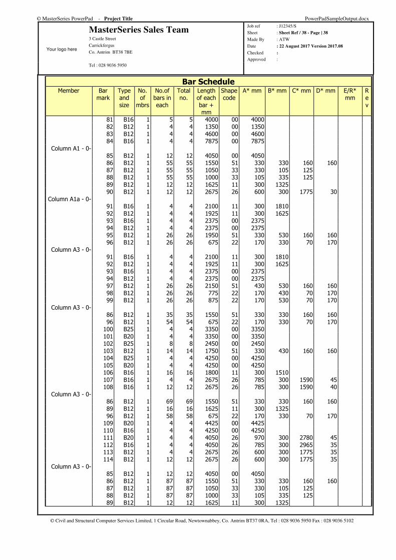
© MasterSeries PowerPad - Project Title PowerPadSampleOutput.docx
Your logo here
MasterSeries Sales Team 3 Castle Street
Carrickfergus
Co. Antrim BT38 7BE
Job ref : J12345/S
Sheet : Sheet Ref / 38 - Page | 38
Made By : ATW
Date : 22 August 2017 Version 2017.08
Checked :
Approved : Tel : 028 9036 5950
© Civil and Structural Computer Services Limited, 1 Circular Road, Newtownabbey, Co. Antrim BT37 0RA, Tel : 028 9036 5950 Fax : 028 9036 5102
Bar Schedule Member Bar
mark Type and size
No. of
mbrs
No.of bars in each
Total no.
Length of each bar + mm
Shape code
A* mm B* mm C* mm D* mm E/R* mm
R e v
81 B16 1 5 5 4000 00 4000 82 B12 1 4 4 1350 00 1350 83 B12 1 4 4 4600 00 4600 84 B16 1 4 4 7875 00 7875
Column A1 - 0- 85 B12 1 12 12 4050 00 4050 86 B12 1 55 55 1550 51 330 330 160 160 87 B12 1 55 55 1050 33 330 105 125 88 B12 1 55 55 1000 33 105 335 125 89 B12 1 12 12 1625 11 300 1325 90 B12 1 12 12 2675 26 600 300 1775 30
Column A1a - 0- 91 B16 1 4 4 2100 11 300 1810 92 B12 1 4 4 1925 11 300 1625 93 B16 1 4 4 2375 00 2375 94 B12 1 4 4 2375 00 2375 95 B12 1 26 26 1950 51 330 530 160 160 96 B12 1 26 26 675 22 170 330 70 170
Column A3 - 0- 91 B16 1 4 4 2100 11 300 1810 92 B12 1 4 4 1925 11 300 1625 93 B16 1 4 4 2375 00 2375 94 B12 1 4 4 2375 00 2375 97 B12 1 26 26 2150 51 430 530 160 160 98 B12 1 26 26 775 22 170 430 70 170 99 B12 1 26 26 875 22 170 530 70 170
Column A3 - 0- 86 B12 1 35 35 1550 51 330 330 160 160 96 B12 1 54 54 675 22 170 330 70 170 100 B25 1 4 4 3350 00 3350 101 B20 1 4 4 3350 00 3350 102 B25 1 8 8 2450 00 2450 103 B12 1 14 14 1750 51 330 430 160 160 104 B25 1 4 4 4250 00 4250 105 B20 1 4 4 4250 00 4250 106 B16 1 16 16 1800 11 300 1510 107 B16 1 4 4 2675 26 785 300 1590 45 108 B16 1 12 12 2675 26 785 300 1590 40
Column A3 - 0- 86 B12 1 69 69 1550 51 330 330 160 160 89 B12 1 16 16 1625 11 300 1325 96 B12 1 58 58 675 22 170 330 70 170 109 B20 1 4 4 4425 00 4425 110 B16 1 4 4 4250 00 4250 111 B20 1 4 4 4050 26 970 300 2780 45 112 B16 1 4 4 4050 26 785 300 2965 35 113 B12 1 4 4 2675 26 600 300 1775 35 114 B12 1 12 12 2675 26 600 300 1775 35
Column A3 - 0- 85 B12 1 12 12 4050 00 4050 86 B12 1 87 87 1550 51 330 330 160 160 87 B12 1 87 87 1050 33 330 105 125 88 B12 1 87 87 1000 33 105 335 125 89 B12 1 12 12 1625 11 300 1325
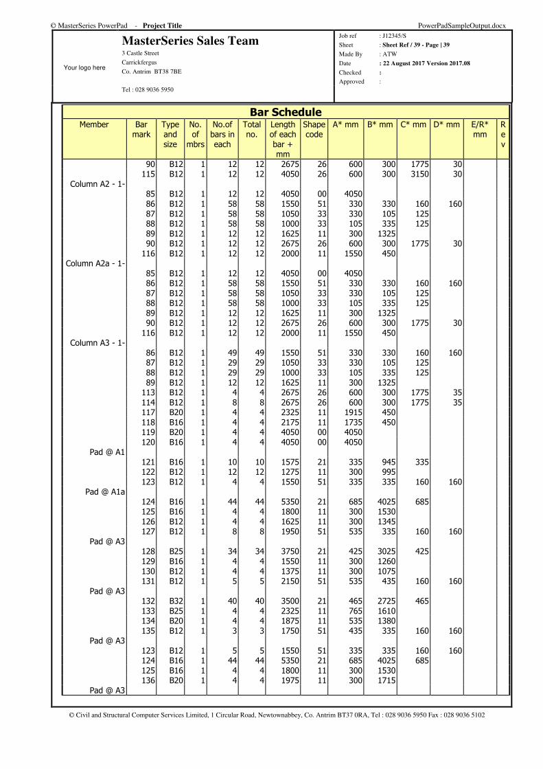
© MasterSeries PowerPad - Project Title PowerPadSampleOutput.docx
Your logo here
MasterSeries Sales Team 3 Castle Street
Carrickfergus
Co. Antrim BT38 7BE
Job ref : J12345/S
Sheet : Sheet Ref / 39 - Page | 39
Made By : ATW
Date : 22 August 2017 Version 2017.08
Checked :
Approved : Tel : 028 9036 5950
© Civil and Structural Computer Services Limited, 1 Circular Road, Newtownabbey, Co. Antrim BT37 0RA, Tel : 028 9036 5950 Fax : 028 9036 5102
Bar Schedule Member Bar
mark Type and size
No. of
mbrs
No.of bars in each
Total no.
Length of each bar + mm
Shape code
A* mm B* mm C* mm D* mm E/R* mm
R e v
90 B12 1 12 12 2675 26 600 300 1775 30 115 B12 1 12 12 4050 26 600 300 3150 30
Column A2 - 1- 85 B12 1 12 12 4050 00 4050 86 B12 1 58 58 1550 51 330 330 160 160 87 B12 1 58 58 1050 33 330 105 125 88 B12 1 58 58 1000 33 105 335 125 89 B12 1 12 12 1625 11 300 1325 90 B12 1 12 12 2675 26 600 300 1775 30 116 B12 1 12 12 2000 11 1550 450
Column A2a - 1- 85 B12 1 12 12 4050 00 4050 86 B12 1 58 58 1550 51 330 330 160 160 87 B12 1 58 58 1050 33 330 105 125 88 B12 1 58 58 1000 33 105 335 125 89 B12 1 12 12 1625 11 300 1325 90 B12 1 12 12 2675 26 600 300 1775 30 116 B12 1 12 12 2000 11 1550 450
Column A3 - 1- 86 B12 1 49 49 1550 51 330 330 160 160 87 B12 1 29 29 1050 33 330 105 125 88 B12 1 29 29 1000 33 105 335 125 89 B12 1 12 12 1625 11 300 1325 113 B12 1 4 4 2675 26 600 300 1775 35 114 B12 1 8 8 2675 26 600 300 1775 35 117 B20 1 4 4 2325 11 1915 450 118 B16 1 4 4 2175 11 1735 450 119 B20 1 4 4 4050 00 4050 120 B16 1 4 4 4050 00 4050
Pad @ A1 121 B16 1 10 10 1575 21 335 945 335 122 B12 1 12 12 1275 11 300 995 123 B12 1 4 4 1550 51 335 335 160 160
Pad @ A1a 124 B16 1 44 44 5350 21 685 4025 685 125 B16 1 4 4 1800 11 300 1530 126 B12 1 4 4 1625 11 300 1345 127 B12 1 8 8 1950 51 535 335 160 160
Pad @ A3 128 B25 1 34 34 3750 21 425 3025 425 129 B16 1 4 4 1550 11 300 1260 130 B12 1 4 4 1375 11 300 1075 131 B12 1 5 5 2150 51 535 435 160 160
Pad @ A3 132 B32 1 40 40 3500 21 465 2725 465 133 B25 1 4 4 2325 11 765 1610 134 B20 1 4 4 1875 11 535 1380 135 B12 1 3 3 1750 51 435 335 160 160
Pad @ A3 123 B12 1 5 5 1550 51 335 335 160 160 124 B16 1 44 44 5350 21 685 4025 685 125 B16 1 4 4 1800 11 300 1530 136 B20 1 4 4 1975 11 300 1715
Pad @ A3
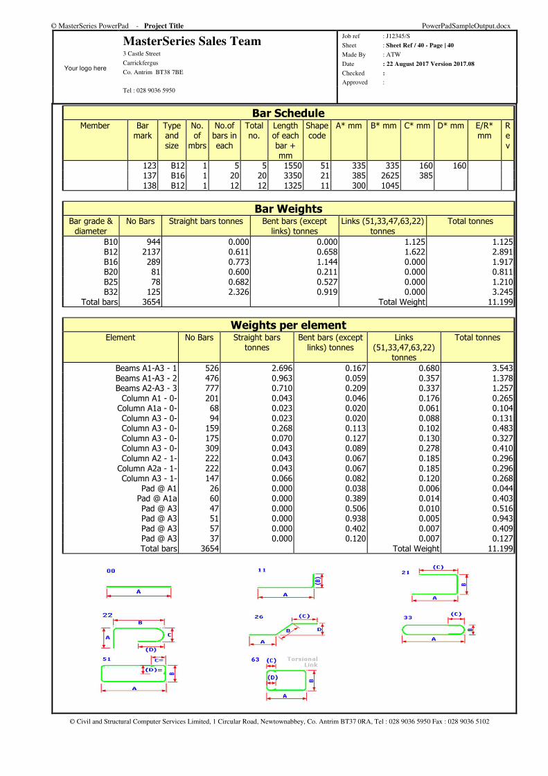
© MasterSeries PowerPad - Project Title PowerPadSampleOutput.docx
Your logo here
MasterSeries Sales Team 3 Castle Street
Carrickfergus
Co. Antrim BT38 7BE
Job ref : J12345/S
Sheet : Sheet Ref / 40 - Page | 40
Made By : ATW
Date : 22 August 2017 Version 2017.08
Checked :
Approved : Tel : 028 9036 5950
© Civil and Structural Computer Services Limited, 1 Circular Road, Newtownabbey, Co. Antrim BT37 0RA, Tel : 028 9036 5950 Fax : 028 9036 5102
Bar Schedule Member Bar
mark Type and size
No. of
mbrs
No.of bars in each
Total no.
Length of each bar + mm
Shape code
A* mm B* mm C* mm D* mm E/R* mm
R e v
123 B12 1 5 5 1550 51 335 335 160 160 137 B16 1 20 20 3350 21 385 2625 385 138 B12 1 12 12 1325 11 300 1045
Bar Weights Bar grade &
diameter No Bars Straight bars tonnes Bent bars (except
links) tonnes Links (51,33,47,63,22)
tonnes Total tonnes
B10 944 0.000 0.000 1.125 1.125 B12 2137 0.611 0.658 1.622 2.891 B16 289 0.773 1.144 0.000 1.917 B20 81 0.600 0.211 0.000 0.811 B25 78 0.682 0.527 0.000 1.210 B32 125 2.326 0.919 0.000 3.245
Total bars 3654 Total Weight 11.199
Weights per element Element No Bars Straight bars
tonnes Bent bars (except
links) tonnes Links
(51,33,47,63,22) tonnes
Total tonnes
Beams A1-A3 - 1 526 2.696 0.167 0.680 3.543 Beams A1-A3 - 2 476 0.963 0.059 0.357 1.378 Beams A2-A3 - 3 777 0.710 0.209 0.337 1.257
Column A1 - 0- 201 0.043 0.046 0.176 0.265 Column A1a - 0- 68 0.023 0.020 0.061 0.104 Column A3 - 0- 94 0.023 0.020 0.088 0.131 Column A3 - 0- 159 0.268 0.113 0.102 0.483 Column A3 - 0- 175 0.070 0.127 0.130 0.327 Column A3 - 0- 309 0.043 0.089 0.278 0.410 Column A2 - 1- 222 0.043 0.067 0.185 0.296
Column A2a - 1- 222 0.043 0.067 0.185 0.296 Column A3 - 1- 147 0.066 0.082 0.120 0.268
Pad @ A1 26 0.000 0.038 0.006 0.044 Pad @ A1a 60 0.000 0.389 0.014 0.403 Pad @ A3 47 0.000 0.506 0.010 0.516 Pad @ A3 51 0.000 0.938 0.005 0.943 Pad @ A3 57 0.000 0.402 0.007 0.409 Pad @ A3 37 0.000 0.120 0.007 0.127 Total bars 3654 Total Weight 11.199
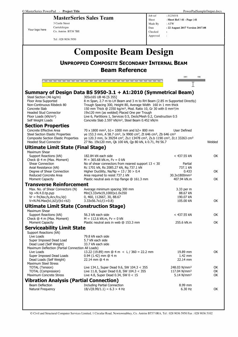
© MasterSeries PowerPad - Project Title PowerPadSampleOutput.docx
Your logo here
MasterSeries Sales Team 3 Castle Street
Carrickfergus
Co. Antrim BT38 7BE
Job ref : J12345/S
Sheet : Sheet Ref / 41 - Page | 41
Made By : ATW
Date : 22 August 2017 Version 2017.08
Checked :
Approved : Tel : 028 9036 5950
© Civil and Structural Computer Services Limited, 1 Circular Road, Newtownabbey, Co. Antrim BT37 0RA, Tel : 028 9036 5950 Fax : 028 9036 5102
Composite Beam Design UNPROPPED COMPOSITE SECONDARY INTERNAL BEAM
Beam Reference
Summary of Design Data BS 5950-3.1 + A1:2010 (Symmetrical Beam) Steel Section (46 kg/m) 305x165 UB 46 [S 355] Floor Area Supported 8 m Span, 2.7 m to LH Beam and 3 m to RH Beam (2.85 m Supported Directly) Non-Continuous Ribdeck 80 Trough Spacing 300, Height 80, Average Width 160 in 1 mm thick Concrete Slab 150 mm Thick @ 2350 kg/m³, Mod. Ratio 10, Gr 30 with 0 mm²/m Headed Stud Connector 19x120 mm (as welded) Placed One per Trough Floor Loads (kN/m²) Live 6, Partitions 1, Services 0.5, Deck/Mesh 0.2, Construction 0.5 Self Weight Loads Concrete Slab 2.597 kN/m², Steel Beam 0.452 kN/m
Section Properties Concrete Effective Area 70 x 1800 mm², b1= 1000 mm and b2= 800 mm User Defined Steel Section Elastic Properties ye 153.3 mm, A 58.7 cm², Ix 9900 cm4, Zt 646 cm³, Zb 646 cm³ Composite Section Elastic Properties ye 120.3 mm, Ix 39254 cm4, Zs.t 13478 cm³, Zs.b 1190 cm³, Zc.t 33263 cm³ Headed Stud Connector 27 No. 19x120 mm, Qk 100 kN, Qp 80 kN, k 0.71, Pd 56.7 Welded
Ultimate Limit State (Final Stage) Maximum Shear Support Reactions (kN) 182.84 kN each side < 437.55 kN OK Check @ 4 m (Max. Moment) M = 365.68 kN.m, Fv = 0 kN Shear Connection No of shear connectors from nearest support 13 < 30 Partial Axial Resistance (kN) Rc 1701 kN, Rs 2085.27 kN, Rq 737.1 kN 737.1 kN Degree of Shear Connection Higher Ductility, Na/Np = 13 / 30 > 0.4 0.433 OK Reduced Concrete Area Area required to resist 737.1 kN 30.3x1800mm² Moment Capacity Plastic neutral axis in top flange @ 161.3 mm 407.94 kN.m OK
Transverse Reinforcement Max. No. of Shear Connectors (N) Average minimum spacing 300 mm 3.33 per m Vp =N.4.D.tp.pyp Min(3.33x4x19,1000)x1.0x350 88.67 kN Vr = fn(Asv,fy,Acv,fcu,Vp) 0, 460, 112667, 30, 88.67 190.07 kN V=N.Pd.Max(b1,b2)/(b1+b2) 3.33x56.7x1/(1+0.8) 105.00 kN OK
Ultimate Limit State (Construction Stage) Maximum Shear Support Reactions (kN) 56.3 kN each side < 437.55 kN OK Check @ 4 m (Max. Moment) M = 112.6 kN.m, Fv = 0 kN Moment Capacity Plastic neutral axis in web @ 153.3 mm 255.6 kN.m OK
Serviceability Limit State Support Reactions (kN) Live Loads 79.8 kN each side Super Imposed Dead Load 5.7 kN each side Dead Load (Self Weight) 33.7 kN each side Maximum Deflection (Partial Connection All Loads) Live Loads 13.22 (19.89) mm @ 4 m < L / 360 = 22.2 mm 19.89 mm OK Super Imposed Dead Loads 0.94 (1.42) mm @ 4 m 1.42 mm Dead Loads (Self Weight) 22.14 mm @ 4 m 22.14 mm Maximum Steel Stress TOTAL (Tension) Live 134.1, Super Dead 9.6, SW 104.3 < 355 248.03 N/mm² OK TOTAL (Compression) Live 11.8, Super Dead 0.8, SW 104.3 < 355 117.04 N/mm² OK Maximum Concrete Stress Live 4.8, Super Dead 0.34, SW 0 < 15 5.14 N/mm² OK
Vibration Analysis (Partial Connection) Beam Deflection Including Partial Connection 8.99 mm Natural Frequency 18/√(8.99/1.1) = 6.3 > 4 Hz 6.30 Hz OK
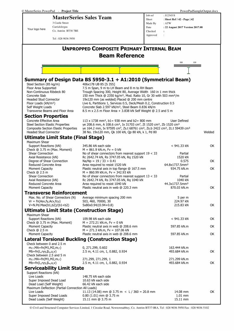
© MasterSeries PowerPad - Project Title PowerPadSampleOutput.docx
Your logo here
MasterSeries Sales Team 3 Castle Street
Carrickfergus
Co. Antrim BT38 7BE
Job ref : J12345/S
Sheet : Sheet Ref / 42 - Page | 42
Made By : ATW
Date : 22 August 2017 Version 2017.08
Checked :
Approved : Tel : 028 9036 5950
© Civil and Structural Computer Services Limited, 1 Circular Road, Newtownabbey, Co. Antrim BT37 0RA, Tel : 028 9036 5950 Fax : 028 9036 5102
UNPROPPED COMPOSITE PRIMARY INTERNAL BEAM
Beam Reference
Summary of Design Data BS 5950-3.1 + A1:2010 (Symmetrical Beam) Steel Section (85 kg/m) 406x178 UB 85 [S 355] Floor Area Supported 7.5 m Span, 9 m to LH Beam and 8 m to RH Beam Non-Continuous Ribdeck 80 Trough Spacing 300, Height 80, Average Width 160 in 1 mm thick Concrete Slab 150 mm Thick @ 2350 kg/m³, Mod. Ratio 10, Gr 30 with 503 mm²/m Headed Stud Connector 19x120 mm (as welded) Placed @ 200 mm centre Floor Loads (kN/m²) Live 6, Partitions 1, Services 0.5, Deck/Mesh 0.2, Construction 0.5 Self Weight Loads Concrete Slab 2.597 kN/m², Steel Beam 0.836 kN/m Transverse Beams and Floor Area 8.5 m x 2.5 m Floor Area + 3.838 kN Self Weight @ 2.5 and 5 m
Section Properties Concrete Effective Area 113 x 1738 mm², b1= 938 mm and b2= 800 mm User Defined Steel Section Elastic Properties ye 208.6 mm, A 108.6 cm², Ix 31703 cm4, Zt 1520 cm³, Zb 1520 cm³ Composite Section Elastic Properties ye 164.2 mm, Ix 97595 cm4, Zs.t 68761 cm³, Zs.b 2422 cm³, Zc.t 59439 cm³ Headed Stud Connector 38 No. 19x120 mm, Qk 100 kN, Qp 80 kN, k 1, Pd 80 Welded
Ultimate Limit State (Final Stage) Maximum Shear Support Reactions (kN) 345.86 kN each side < 941.33 kN OK Check @ 3.75 m (Max. Moment) M = 861.9 kN.m, Fv = 0 kN Shear Connection No of shear connectors from nearest support 19 < 33 Partial Axial Resistance (kN) Rc 2642.74 kN, Rs 3747.05 kN, Rq 1520 kN 1520 kN Degree of Shear Connection Na/Np = 19 / 33 > 0.41 0.575 OK Reduced Concrete Area Area required to resist 1520 kN 64.8x1737.5mm² Moment Capacity Plastic neutral axis in top flange @ 167.5 mm 934.75 kN.m OK Check @ 2.5 m M = 860.99 kN.m, Fv = 342.93 kN Shear Connection No of shear connectors from nearest support 13 < 33 Partial Axial Resistance (kN) Rc 2642.74 kN, Rs 3747.05 kN, Rq 1040 kN 1040 kN Reduced Concrete Area Area required to resist 1040 kN 44.3x1737.5mm² Moment Capacity Plastic neutral axis in web @ 220.3 mm 870.03 kN.m OK
Transverse Reinforcement Max. No. of Shear Connectors (N) Average minimum spacing 200 mm 5 per m Vr = fn(Asv,fy,Acv,fcu) 503, 460, 70000, 30 224.97 kN V=N.Pd.Max(b1,b2)/(b1+b2) 5x80x0.94/(0.94+0.8) 215.83 kN OK
Ultimate Limit State (Construction Stage) Maximum Shear Support Reactions (kN) 109.98 kN each side < 941.33 kN OK Check @ 3.75 m (Max. Moment) M = 272.21 kN.m, Fv = 0 kN Moment Capacity Plastic neutral axis in web @ 208.6 mm 597.85 kN.m OK Check @ 2.5 m M = 271.3 kN.m, Fv = 107.06 kN Moment Capacity Plastic neutral axis in web @ 208.6 mm 597.85 kN.m OK
Lateral Torsional Buckling (Construction Stage) Check between 0 and 2.5 m mLT.MA=fn(M1,M2,mLT) 0, 271.299, 0.602 163.444 kN.m Mb=fn(L,ryy,βw,u,v) 2.5 m, 4.11 cm, 1, 0.882, 0.934 493.684 kN.m OK Check between 2.5 and 5 m mLT.MA=fn(M1,M2,mLT) 271.299, 271.299, 1 271.299 kN.m Mb=fn(L,ryy,βw,u,v) 2.5 m, 4.11 cm, 1, 0.882, 0.934 493.684 kN.m OK
Serviceability Limit State Support Reactions (kN) Live Loads 148.75 kN each side Super Imposed Dead Load 10.63 kN each side Dead Load (Self Weight) 66.42 kN each side Maximum Deflection (Partial Connection All Loads) Live Loads 11.13 (14.08) mm @ 3.75 m < L / 360 = 20.8 mm 14.08 mm OK Super Imposed Dead Loads 0.80 (1.01) mm @ 3.75 m 1.01 mm Dead Loads (Self Weight) 15.11 mm @ 3.75 m 15.11 mm
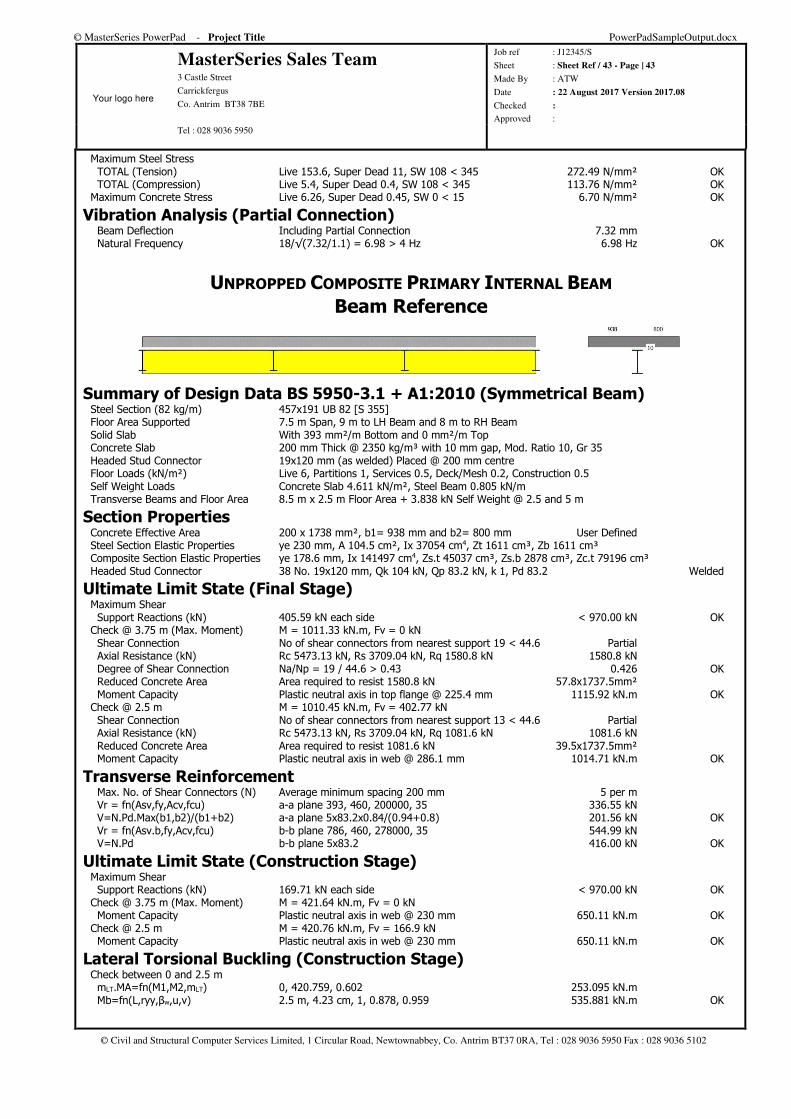
© MasterSeries PowerPad - Project Title PowerPadSampleOutput.docx
Your logo here
MasterSeries Sales Team 3 Castle Street
Carrickfergus
Co. Antrim BT38 7BE
Job ref : J12345/S
Sheet : Sheet Ref / 43 - Page | 43
Made By : ATW
Date : 22 August 2017 Version 2017.08
Checked :
Approved : Tel : 028 9036 5950
© Civil and Structural Computer Services Limited, 1 Circular Road, Newtownabbey, Co. Antrim BT37 0RA, Tel : 028 9036 5950 Fax : 028 9036 5102
Maximum Steel Stress TOTAL (Tension) Live 153.6, Super Dead 11, SW 108 < 345 272.49 N/mm² OK TOTAL (Compression) Live 5.4, Super Dead 0.4, SW 108 < 345 113.76 N/mm² OK Maximum Concrete Stress Live 6.26, Super Dead 0.45, SW 0 < 15 6.70 N/mm² OK
Vibration Analysis (Partial Connection) Beam Deflection Including Partial Connection 7.32 mm Natural Frequency 18/√(7.32/1.1) = 6.98 > 4 Hz 6.98 Hz OK
UNPROPPED COMPOSITE PRIMARY INTERNAL BEAM
Beam Reference
Summary of Design Data BS 5950-3.1 + A1:2010 (Symmetrical Beam) Steel Section (82 kg/m) 457x191 UB 82 [S 355] Floor Area Supported 7.5 m Span, 9 m to LH Beam and 8 m to RH Beam Solid Slab With 393 mm²/m Bottom and 0 mm²/m Top Concrete Slab 200 mm Thick @ 2350 kg/m³ with 10 mm gap, Mod. Ratio 10, Gr 35 Headed Stud Connector 19x120 mm (as welded) Placed @ 200 mm centre Floor Loads (kN/m²) Live 6, Partitions 1, Services 0.5, Deck/Mesh 0.2, Construction 0.5 Self Weight Loads Concrete Slab 4.611 kN/m², Steel Beam 0.805 kN/m Transverse Beams and Floor Area 8.5 m x 2.5 m Floor Area + 3.838 kN Self Weight @ 2.5 and 5 m
Section Properties Concrete Effective Area 200 x 1738 mm², b1= 938 mm and b2= 800 mm User Defined Steel Section Elastic Properties ye 230 mm, A 104.5 cm², Ix 37054 cm4, Zt 1611 cm³, Zb 1611 cm³ Composite Section Elastic Properties ye 178.6 mm, Ix 141497 cm4, Zs.t 45037 cm³, Zs.b 2878 cm³, Zc.t 79196 cm³ Headed Stud Connector 38 No. 19x120 mm, Qk 104 kN, Qp 83.2 kN, k 1, Pd 83.2 Welded
Ultimate Limit State (Final Stage) Maximum Shear Support Reactions (kN) 405.59 kN each side < 970.00 kN OK Check @ 3.75 m (Max. Moment) M = 1011.33 kN.m, Fv = 0 kN Shear Connection No of shear connectors from nearest support 19 < 44.6 Partial Axial Resistance (kN) Rc 5473.13 kN, Rs 3709.04 kN, Rq 1580.8 kN 1580.8 kN Degree of Shear Connection Na/Np = 19 / 44.6 > 0.43 0.426 OK Reduced Concrete Area Area required to resist 1580.8 kN 57.8x1737.5mm² Moment Capacity Plastic neutral axis in top flange @ 225.4 mm 1115.92 kN.m OK Check @ 2.5 m M = 1010.45 kN.m, Fv = 402.77 kN Shear Connection No of shear connectors from nearest support 13 < 44.6 Partial Axial Resistance (kN) Rc 5473.13 kN, Rs 3709.04 kN, Rq 1081.6 kN 1081.6 kN Reduced Concrete Area Area required to resist 1081.6 kN 39.5x1737.5mm² Moment Capacity Plastic neutral axis in web @ 286.1 mm 1014.71 kN.m OK
Transverse Reinforcement Max. No. of Shear Connectors (N) Average minimum spacing 200 mm 5 per m Vr = fn(Asv,fy,Acv,fcu) a-a plane 393, 460, 200000, 35 336.55 kN V=N.Pd.Max(b1,b2)/(b1+b2) a-a plane 5x83.2x0.84/(0.94+0.8) 201.56 kN OK Vr = fn(Asv.b,fy,Acv,fcu) b-b plane 786, 460, 278000, 35 544.99 kN V=N.Pd b-b plane 5x83.2 416.00 kN OK
Ultimate Limit State (Construction Stage) Maximum Shear Support Reactions (kN) 169.71 kN each side < 970.00 kN OK Check @ 3.75 m (Max. Moment) M = 421.64 kN.m, Fv = 0 kN Moment Capacity Plastic neutral axis in web @ 230 mm 650.11 kN.m OK Check @ 2.5 m M = 420.76 kN.m, Fv = 166.9 kN Moment Capacity Plastic neutral axis in web @ 230 mm 650.11 kN.m OK
Lateral Torsional Buckling (Construction Stage) Check between 0 and 2.5 m mLT.MA=fn(M1,M2,mLT) 0, 420.759, 0.602 253.095 kN.m Mb=fn(L,ryy,βw,u,v) 2.5 m, 4.23 cm, 1, 0.878, 0.959 535.881 kN.m OK
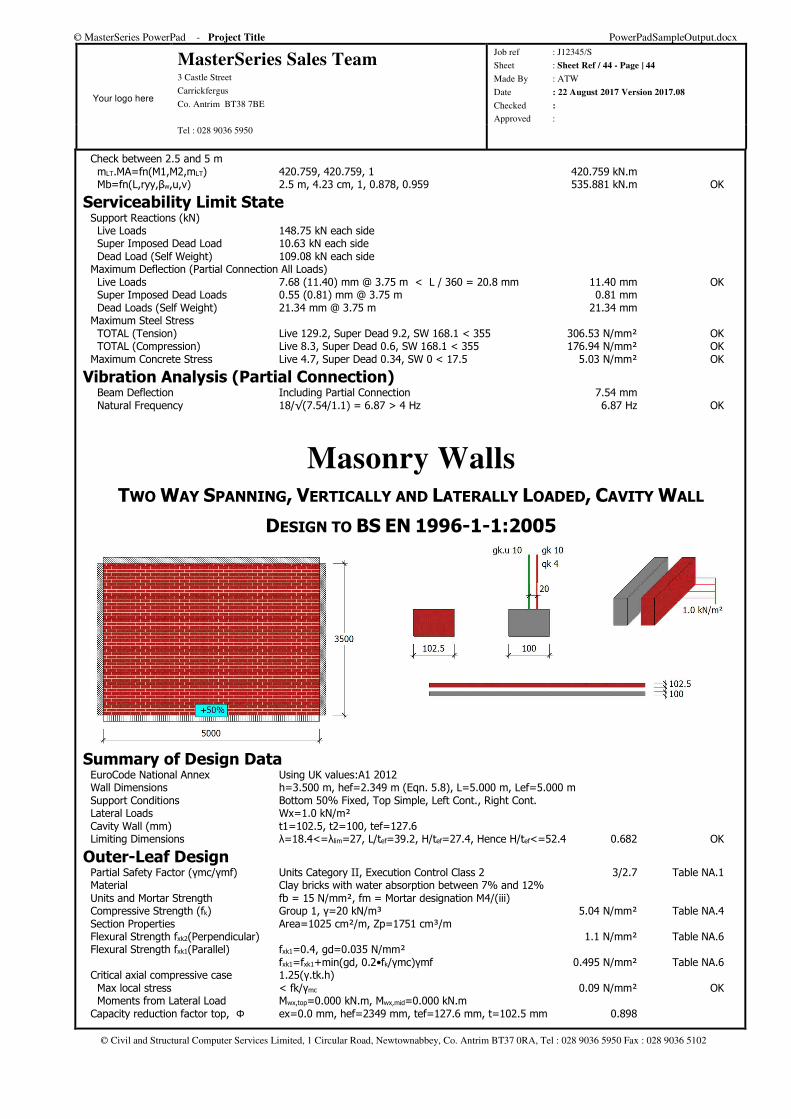
© MasterSeries PowerPad - Project Title PowerPadSampleOutput.docx
Your logo here
MasterSeries Sales Team 3 Castle Street
Carrickfergus
Co. Antrim BT38 7BE
Job ref : J12345/S
Sheet : Sheet Ref / 44 - Page | 44
Made By : ATW
Date : 22 August 2017 Version 2017.08
Checked :
Approved : Tel : 028 9036 5950
© Civil and Structural Computer Services Limited, 1 Circular Road, Newtownabbey, Co. Antrim BT37 0RA, Tel : 028 9036 5950 Fax : 028 9036 5102
Check between 2.5 and 5 m mLT.MA=fn(M1,M2,mLT) 420.759, 420.759, 1 420.759 kN.m Mb=fn(L,ryy,βw,u,v) 2.5 m, 4.23 cm, 1, 0.878, 0.959 535.881 kN.m OK
Serviceability Limit State Support Reactions (kN) Live Loads 148.75 kN each side Super Imposed Dead Load 10.63 kN each side Dead Load (Self Weight) 109.08 kN each side Maximum Deflection (Partial Connection All Loads) Live Loads 7.68 (11.40) mm @ 3.75 m < L / 360 = 20.8 mm 11.40 mm OK Super Imposed Dead Loads 0.55 (0.81) mm @ 3.75 m 0.81 mm Dead Loads (Self Weight) 21.34 mm @ 3.75 m 21.34 mm Maximum Steel Stress TOTAL (Tension) Live 129.2, Super Dead 9.2, SW 168.1 < 355 306.53 N/mm² OK TOTAL (Compression) Live 8.3, Super Dead 0.6, SW 168.1 < 355 176.94 N/mm² OK Maximum Concrete Stress Live 4.7, Super Dead 0.34, SW 0 < 17.5 5.03 N/mm² OK
Vibration Analysis (Partial Connection) Beam Deflection Including Partial Connection 7.54 mm Natural Frequency 18/√(7.54/1.1) = 6.87 > 4 Hz 6.87 Hz OK
Masonry Walls TWO WAY SPANNING, VERTICALLY AND LATERALLY LOADED, CAVITY WALL
DESIGN TO BS EN 1996-1-1:2005
Summary of Design Data EuroCode National Annex Using UK values:A1 2012 Wall Dimensions h=3.500 m, hef=2.349 m (Eqn. 5.8), L=5.000 m, Lef=5.000 m Support Conditions Bottom 50% Fixed, Top Simple, Left Cont., Right Cont. Lateral Loads Wx=1.0 kN/m² Cavity Wall (mm) t1=102.5, t2=100, tef=127.6 Limiting Dimensions λ=18.4<=λlim=27, L/tef=39.2, H/tef=27.4, Hence H/tef<=52.4 0.682 OK
Outer-Leaf Design Partial Safety Factor (γmc/γmf) Units Category II, Execution Control Class 2 3/2.7 Table NA.1 Material Clay bricks with water absorption between 7% and 12% Units and Mortar Strength fb = 15 N/mm², fm = Mortar designation M4/(iii) Compressive Strength (fk) Group 1, γ=20 kN/m³ 5.04 N/mm² Table NA.4 Section Properties Area=1025 cm²/m, Zp=1751 cm³/m Flexural Strength fxk2(Perpendicular) 1.1 N/mm² Table NA.6 Flexural Strength fxk1(Parallel) fxk1=0.4, gd=0.035 N/mm² fxk1=fxk1+min(gd, 0.2•fk/γmc)γmf 0.495 N/mm² Table NA.6 Critical axial compressive case 1.25(γ.tk.h) Max local stress < fk/γmc 0.09 N/mm² OK Moments from Lateral Load Mwx,top=0.000 kN.m, Mwx,mid=0.000 kN.m Capacity reduction factor top, Φ ex=0.0 mm, hef=2349 mm, tef=127.6 mm, t=102.5 mm 0.898
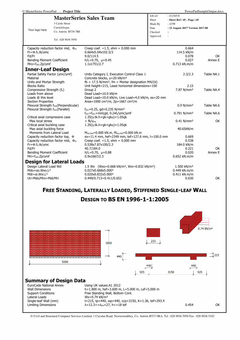
© MasterSeries PowerPad - Project Title PowerPadSampleOutput.docx
Your logo here
MasterSeries Sales Team 3 Castle Street
Carrickfergus
Co. Antrim BT38 7BE
Job ref : J12345/S
Sheet : Sheet Ref / 45 - Page | 45
Made By : ATW
Date : 22 August 2017 Version 2017.08
Checked :
Approved : Tel : 028 9036 5950
© Civil and Structural Computer Services Limited, 1 Circular Road, Newtownabbey, Co. Antrim BT37 0RA, Tel : 028 9036 5950 Fax : 028 9036 5102
Capacity reduction factor mid, Φm Creep coef. =1.5, ehm = 0.000 mm 0.664 Fr=Φ.fk.tk/γmc 0.664x5.04x102.5/3 114.5 kN/m Fd/Fr 9.0/114.5 0.078 OK Bending Moment Coefficient h/L=0.70, µ=0.45 0.027 Annex E Mro=fxk2.Zp/γmf 1.1x1751/2.7 0.713 kN.m/m
Inner-Leaf Design Partial Safety Factor (γmc/γmf) Units Category I, Execution Control Class 1 2.3/2.3 Table NA.1 Material Concrete blocks, γ=20 kN/m³ Units and Mortar Strength fb = 17.5 N/mm², fm = Mortar designation M4/(iii) Blocks Ratio Unit height=215, Least horizontal dimensions=100 2.15 Compressive Strength (fk) Group 2 7.87 N/mm² Table NA.4 Loads from above Dead Load=10.0 kN/m Loads @ this level Dead Load=10.0 kN/m, Live Load=4.0 kN/m, ex=20 mm Section Properties Area=1000 cm²/m, Zp=1667 cm³/m Flexural Strength fxk2(Perpendicular) 0.9 N/mm² Table NA.6 Flexural Strength fxk1(Parallel) fxk1=0.25, gd=0.235 N/mm² fxk1=fxk1+min(gd, 0.2•fk/γmc)γmf 0.791 N/mm² Table NA.6 Critical axial compressive case 1.35(γ.tk.h+gk+gku)+1.05qk Max local stress < fk/γmc 0.41 N/mm² OK Critical axial buckling case 1.35(γ.tk.h+gk+gku)+1.05qk Max axial buckling force 40.65kN/m Moments from Lateral Load Mwx,top=0.000 kN.m, Mwx,mid=0.000 kN.m Capacity reduction factor top, Φ ex=11.4 mm, hef=2349 mm, tef=127.6 mm, t=100.0 mm 0.669 Capacity reduction factor mid, Φm Creep coef. =1.5, ehm = 0.000 mm 0.538 Fr=Φ.fk.tk/γmc 0.538x7.87x100/2.3 184.0 kN/m Fd/Fr 40.7/184.0 0.221 OK Bending Moment Coefficient h/L=0.70, µ=0.88 0.020 Annex E Mri=fxk2.Zp/γmf 0.9x1667/2.3 0.652 kN.m/m
Design for Lateral Loads Design Lateral Load Wd 1.5 Wx (Wxo=0.668 kN/m², Wxi=0.832 kN/m²) 1.500 kN/m² Mdo=αo.Wxo.L² 0.027x0.668x5.000² 0.449 kN.m/m Mdi=αi.Wxi.L² 0.020x0.832x5.000² 0.411 kN.m/m Ut=Mdo/Mro=Mdi/Mri 0.449/0.713=0.411/0.652 0.630 OK
FREE STANDING, LATERALLY LOADED, STIFFENED SINGLE-LEAF WALL
DESIGN TO BS EN 1996-1-1:2005
Summary of Design Data EuroCode National Annex Using UK values:A1 2012 Wall Dimensions h=1.800 m, hef=3.600 m, L=5.000 m, Lef=5.000 m Support Conditions Free Standing Wall, Bottom Cont. Lateral Loads Wx=0.74 kN/m² Single-leaf Wall (mm) t=215, tp=440, wp=440, ccp=3150, K=1.36, tef=293.4 Limiting Dimensions λ=12.3<=λlim=27, h<=18 tef 0.454 OK
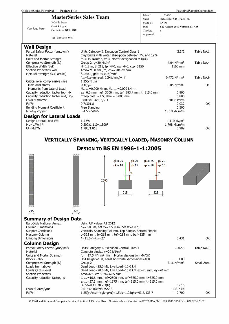
© MasterSeries PowerPad - Project Title PowerPadSampleOutput.docx
Your logo here
MasterSeries Sales Team 3 Castle Street
Carrickfergus
Co. Antrim BT38 7BE
Job ref : J12345/S
Sheet : Sheet Ref / 46 - Page | 46
Made By : ATW
Date : 22 August 2017 Version 2017.08
Checked :
Approved : Tel : 028 9036 5950
© Civil and Structural Computer Services Limited, 1 Circular Road, Newtownabbey, Co. Antrim BT37 0RA, Tel : 028 9036 5950 Fax : 028 9036 5102
Wall Design Partial Safety Factor (γmc/γmf) Units Category I, Execution Control Class 1 2.3/2 Table NA.1 Material Clay bricks with water absorption between 7% and 12% Units and Mortar Strength fb = 15 N/mm², fm = Mortar designation M4/(iii) Compressive Strength (fk) Group 2, γ=20 kN/m³ 4.04 N/mm² Table NA.4 Effective Width (bef) H=1.8 m, t=215, tp=440, wp=440, ccp=3150 1160 mm Section Properties Wall Area=2150 cm²/m, Zb=7704 cm³/m Flexural Strength fxk1(Parallel) fxk1=0.4, gd=0.036 N/mm² fxk1=fxk1+min(gd, 0.2•fk/γmc)γmf 0.472 N/mm² Table NA.6 Critical axial compressive case 1.25(γ.tk.h) Max local stress < fk/γmc 0.05 N/mm² OK Moments from Lateral Load Mwx,top=0.000 kN.m, Mwx,mid=0.000 kN.m Capacity reduction factor top, Φ ex=0.0 mm, hef=3600 mm, tef=293.4 mm, t=215.0 mm 0.900 Capacity reduction factor mid, Φm Creep coef. =1.5, ehm = 0.000 mm 0.800 Fr=Φ.fk.tk/γmc 0.800x4.04x215/2.3 301.8 kN/m Fd/Fr 9.7/301.8 0.032 OK Bending Moment Coefficient Free Standing 0.500 Mr=fxk1.Zb/γmf 0.472x7704/2 1.818 kN.m/m
Design for Lateral Loads Design Lateral Load Wd 1.5 Wx 1.110 kN/m² Md=α.Wx.h² 0.500x1.110x1.800² 1.798 kN.m/m Ut=Md/Mr 1.798/1.818 0.989 OK
VERTICALLY SPANNING, VERTICALLY LOADED, MASONRY COLUMN
DESIGN TO BS EN 1996-1-1:2005
Summary of Design Data EuroCode National Annex Using UK values:A1 2012 Column Dimensions h=2.500 m, hef xx=2.500 m, hef zz=1.875 Support Conditions Vertically Spanning Column, Top Simple, Bottom Simple Masonry Column t=325 mm, b=215 mm, tef=215 mm, bef=325 mm Limiting Dimensions λ=11.6<=λlim=27 0.431 OK
Column Design Partial Safety Factor (γmc/γmf) Units Category I, Execution Control Class 1 2.3/2.3 Table NA.1 Material Concrete blocks, γ=20 kN/m³ Units and Mortar Strength fb = 17.5 N/mm², fm = Mortar designation M4/(iii) Blocks Ratio Unit height=100, Least horizontal dimensions=100 1.00 Compressive Strength (fk) Group 2 7.16 N/mm² Small Area Loads from above Dead Load=25.0 kN, Live Load=10.0 kN Loads @ this level Dead Load=20.0 kN, Live Load=15.0 kN, ex=20 mm, ey=70 mm Section Properties Area=699 cm², Zx=3785 cm³ Capacity reduction factor, Φ emajor=10.6 mm, hef=2500 mm, tef=325.0 mm, t=325.0 mm eminor=37.3 mm, hef=1875 mm, tef=215.0 mm, t=215.0 mm BS 5628 Cl. 28.2.3(b) 0.615 Fr=Φ.fk.Area/γmc 0.615x7.16x698.75/2.3 133.7 kN Fd/Fr 1.25(γ.Area.h+gk+gku)+1.5qk+1.05qku=93.6/133.7 0.700 OK
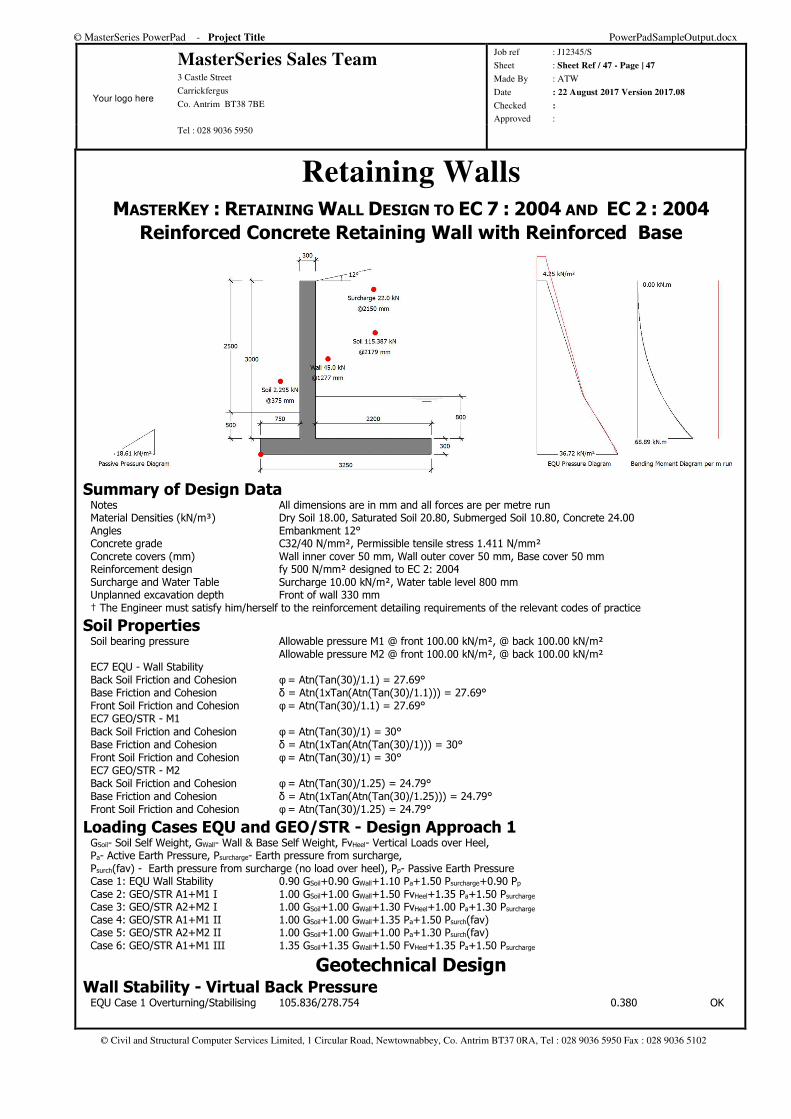
© MasterSeries PowerPad - Project Title PowerPadSampleOutput.docx
Your logo here
MasterSeries Sales Team 3 Castle Street
Carrickfergus
Co. Antrim BT38 7BE
Job ref : J12345/S
Sheet : Sheet Ref / 47 - Page | 47
Made By : ATW
Date : 22 August 2017 Version 2017.08
Checked :
Approved : Tel : 028 9036 5950
© Civil and Structural Computer Services Limited, 1 Circular Road, Newtownabbey, Co. Antrim BT37 0RA, Tel : 028 9036 5950 Fax : 028 9036 5102
Retaining Walls MASTERKEY : RETAINING WALL DESIGN TO EC 7 : 2004 AND EC 2 : 2004
Reinforced Concrete Retaining Wall with Reinforced Base
Summary of Design Data Notes All dimensions are in mm and all forces are per metre run Material Densities (kN/m³) Dry Soil 18.00, Saturated Soil 20.80, Submerged Soil 10.80, Concrete 24.00 Angles Embankment 12° Concrete grade C32/40 N/mm², Permissible tensile stress 1.411 N/mm² Concrete covers (mm) Wall inner cover 50 mm, Wall outer cover 50 mm, Base cover 50 mm Reinforcement design fy 500 N/mm² designed to EC 2: 2004 Surcharge and Water Table Surcharge 10.00 kN/m², Water table level 800 mm Unplanned excavation depth Front of wall 330 mm † The Engineer must satisfy him/herself to the reinforcement detailing requirements of the relevant codes of practice
Soil Properties Soil bearing pressure Allowable pressure M1 @ front 100.00 kN/m², @ back 100.00 kN/m² Allowable pressure M2 @ front 100.00 kN/m², @ back 100.00 kN/m² EC7 EQU - Wall Stability Back Soil Friction and Cohesion φ = Atn(Tan(30)/1.1) = 27.69° Base Friction and Cohesion δ = Atn(1xTan(Atn(Tan(30)/1.1))) = 27.69° Front Soil Friction and Cohesion φ = Atn(Tan(30)/1.1) = 27.69° EC7 GEO/STR - M1 Back Soil Friction and Cohesion φ = Atn(Tan(30)/1) = 30° Base Friction and Cohesion δ = Atn(1xTan(Atn(Tan(30)/1))) = 30° Front Soil Friction and Cohesion φ = Atn(Tan(30)/1) = 30° EC7 GEO/STR - M2 Back Soil Friction and Cohesion φ = Atn(Tan(30)/1.25) = 24.79° Base Friction and Cohesion δ = Atn(1xTan(Atn(Tan(30)/1.25))) = 24.79° Front Soil Friction and Cohesion φ = Atn(Tan(30)/1.25) = 24.79°
Loading Cases EQU and GEO/STR - Design Approach 1 GSoil- Soil Self Weight, GWall- Wall & Base Self Weight, FvHeel- Vertical Loads over Heel, Pa- Active Earth Pressure, Psurcharge- Earth pressure from surcharge, Psurch(fav) - Earth pressure from surcharge (no load over heel), Pp- Passive Earth Pressure Case 1: EQU Wall Stability 0.90 GSoil+0.90 GWall+1.10 Pa+1.50 Psurcharge+0.90 Pp Case 2: GEO/STR A1+M1 I 1.00 GSoil+1.00 GWall+1.50 FvHeel+1.35 Pa+1.50 Psurcharge Case 3: GEO/STR A2+M2 I 1.00 GSoil+1.00 GWall+1.30 FvHeel+1.00 Pa+1.30 Psurcharge Case 4: GEO/STR A1+M1 II 1.00 GSoil+1.00 GWall+1.35 Pa+1.50 Psurch(fav) Case 5: GEO/STR A2+M2 II 1.00 GSoil+1.00 GWall+1.00 Pa+1.30 Psurch(fav) Case 6: GEO/STR A1+M1 III 1.35 GSoil+1.35 GWall+1.50 FvHeel+1.35 Pa+1.50 Psurcharge
Geotechnical Design Wall Stability - Virtual Back Pressure EQU Case 1 Overturning/Stabilising 105.836/278.754 0.380 OK
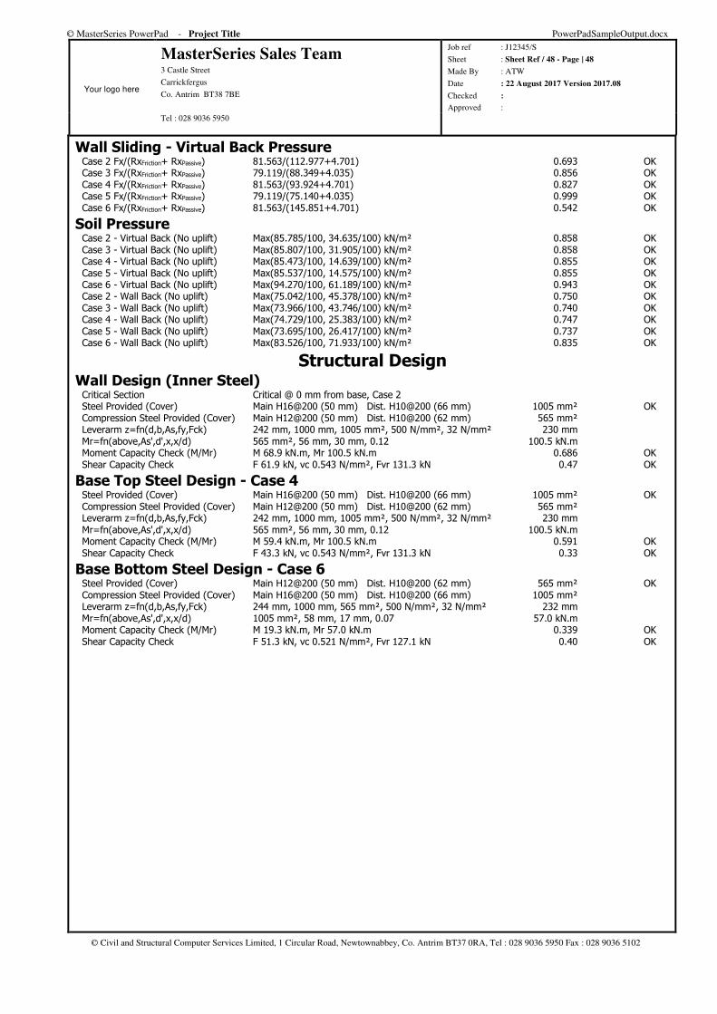
© MasterSeries PowerPad - Project Title PowerPadSampleOutput.docx
Your logo here
MasterSeries Sales Team 3 Castle Street
Carrickfergus
Co. Antrim BT38 7BE
Job ref : J12345/S
Sheet : Sheet Ref / 48 - Page | 48
Made By : ATW
Date : 22 August 2017 Version 2017.08
Checked :
Approved : Tel : 028 9036 5950
© Civil and Structural Computer Services Limited, 1 Circular Road, Newtownabbey, Co. Antrim BT37 0RA, Tel : 028 9036 5950 Fax : 028 9036 5102
Wall Sliding - Virtual Back Pressure Case 2 Fx/(RxFriction+ RxPassive) 81.563/(112.977+4.701) 0.693 OK Case 3 Fx/(RxFriction+ RxPassive) 79.119/(88.349+4.035) 0.856 OK Case 4 Fx/(RxFriction+ RxPassive) 81.563/(93.924+4.701) 0.827 OK Case 5 Fx/(RxFriction+ RxPassive) 79.119/(75.140+4.035) 0.999 OK Case 6 Fx/(RxFriction+ RxPassive) 81.563/(145.851+4.701) 0.542 OK
Soil Pressure Case 2 - Virtual Back (No uplift) Max(85.785/100, 34.635/100) kN/m² 0.858 OK Case 3 - Virtual Back (No uplift) Max(85.807/100, 31.905/100) kN/m² 0.858 OK Case 4 - Virtual Back (No uplift) Max(85.473/100, 14.639/100) kN/m² 0.855 OK Case 5 - Virtual Back (No uplift) Max(85.537/100, 14.575/100) kN/m² 0.855 OK Case 6 - Virtual Back (No uplift) Max(94.270/100, 61.189/100) kN/m² 0.943 OK Case 2 - Wall Back (No uplift) Max(75.042/100, 45.378/100) kN/m² 0.750 OK Case 3 - Wall Back (No uplift) Max(73.966/100, 43.746/100) kN/m² 0.740 OK Case 4 - Wall Back (No uplift) Max(74.729/100, 25.383/100) kN/m² 0.747 OK Case 5 - Wall Back (No uplift) Max(73.695/100, 26.417/100) kN/m² 0.737 OK Case 6 - Wall Back (No uplift) Max(83.526/100, 71.933/100) kN/m² 0.835 OK
Structural Design Wall Design (Inner Steel) Critical Section Critical @ 0 mm from base, Case 2 Steel Provided (Cover) Main H16@200 (50 mm) Dist. H10@200 (66 mm) 1005 mm² OK Compression Steel Provided (Cover) Main H12@200 (50 mm) Dist. H10@200 (62 mm) 565 mm² Leverarm z=fn(d,b,As,fy,Fck) 242 mm, 1000 mm, 1005 mm², 500 N/mm², 32 N/mm² 230 mm Mr=fn(above,As',d',x,x/d) 565 mm², 56 mm, 30 mm, 0.12 100.5 kN.m Moment Capacity Check (M/Mr) M 68.9 kN.m, Mr 100.5 kN.m 0.686 OK Shear Capacity Check F 61.9 kN, vc 0.543 N/mm², Fvr 131.3 kN 0.47 OK
Base Top Steel Design - Case 4 Steel Provided (Cover) Main H16@200 (50 mm) Dist. H10@200 (66 mm) 1005 mm² OK Compression Steel Provided (Cover) Main H12@200 (50 mm) Dist. H10@200 (62 mm) 565 mm² Leverarm z=fn(d,b,As,fy,Fck) 242 mm, 1000 mm, 1005 mm², 500 N/mm², 32 N/mm² 230 mm Mr=fn(above,As',d',x,x/d) 565 mm², 56 mm, 30 mm, 0.12 100.5 kN.m Moment Capacity Check (M/Mr) M 59.4 kN.m, Mr 100.5 kN.m 0.591 OK Shear Capacity Check F 43.3 kN, vc 0.543 N/mm², Fvr 131.3 kN 0.33 OK
Base Bottom Steel Design - Case 6 Steel Provided (Cover) Main H12@200 (50 mm) Dist. H10@200 (62 mm) 565 mm² OK Compression Steel Provided (Cover) Main H16@200 (50 mm) Dist. H10@200 (66 mm) 1005 mm² Leverarm z=fn(d,b,As,fy,Fck) 244 mm, 1000 mm, 565 mm², 500 N/mm², 32 N/mm² 232 mm Mr=fn(above,As',d',x,x/d) 1005 mm², 58 mm, 17 mm, 0.07 57.0 kN.m Moment Capacity Check (M/Mr) M 19.3 kN.m, Mr 57.0 kN.m 0.339 OK Shear Capacity Check F 51.3 kN, vc 0.521 N/mm², Fvr 127.1 kN 0.40 OK
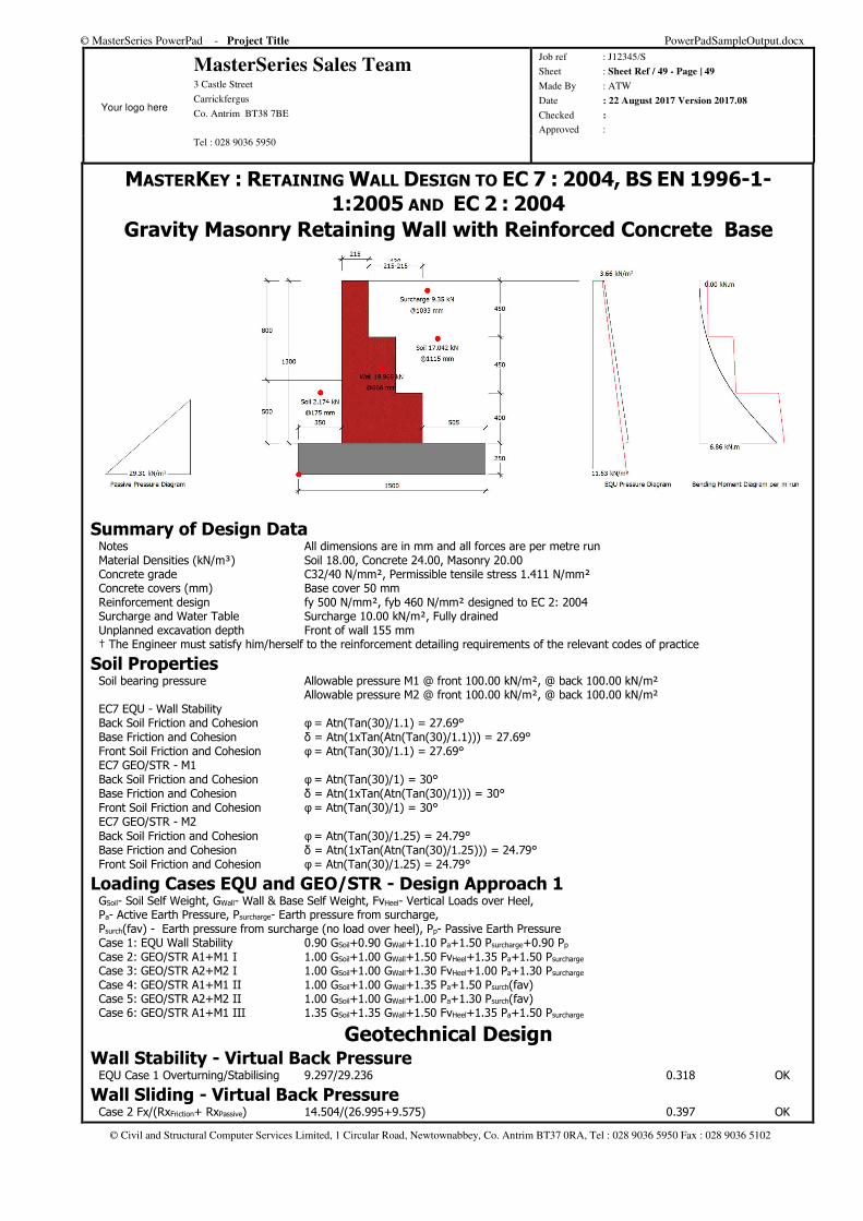
© MasterSeries PowerPad - Project Title PowerPadSampleOutput.docx
Your logo here
MasterSeries Sales Team 3 Castle Street
Carrickfergus
Co. Antrim BT38 7BE
Job ref : J12345/S
Sheet : Sheet Ref / 49 - Page | 49
Made By : ATW
Date : 22 August 2017 Version 2017.08
Checked :
Approved : Tel : 028 9036 5950
© Civil and Structural Computer Services Limited, 1 Circular Road, Newtownabbey, Co. Antrim BT37 0RA, Tel : 028 9036 5950 Fax : 028 9036 5102
MASTERKEY : RETAINING WALL DESIGN TO EC 7 : 2004, BS EN 1996-1-1:2005 AND EC 2 : 2004
Gravity Masonry Retaining Wall with Reinforced Concrete Base
Summary of Design Data Notes All dimensions are in mm and all forces are per metre run Material Densities (kN/m³) Soil 18.00, Concrete 24.00, Masonry 20.00 Concrete grade C32/40 N/mm², Permissible tensile stress 1.411 N/mm² Concrete covers (mm) Base cover 50 mm Reinforcement design fy 500 N/mm², fyb 460 N/mm² designed to EC 2: 2004 Surcharge and Water Table Surcharge 10.00 kN/m², Fully drained Unplanned excavation depth Front of wall 155 mm † The Engineer must satisfy him/herself to the reinforcement detailing requirements of the relevant codes of practice
Soil Properties Soil bearing pressure Allowable pressure M1 @ front 100.00 kN/m², @ back 100.00 kN/m² Allowable pressure M2 @ front 100.00 kN/m², @ back 100.00 kN/m² EC7 EQU - Wall Stability Back Soil Friction and Cohesion φ = Atn(Tan(30)/1.1) = 27.69° Base Friction and Cohesion δ = Atn(1xTan(Atn(Tan(30)/1.1))) = 27.69° Front Soil Friction and Cohesion φ = Atn(Tan(30)/1.1) = 27.69° EC7 GEO/STR - M1 Back Soil Friction and Cohesion φ = Atn(Tan(30)/1) = 30° Base Friction and Cohesion δ = Atn(1xTan(Atn(Tan(30)/1))) = 30° Front Soil Friction and Cohesion φ = Atn(Tan(30)/1) = 30° EC7 GEO/STR - M2 Back Soil Friction and Cohesion φ = Atn(Tan(30)/1.25) = 24.79° Base Friction and Cohesion δ = Atn(1xTan(Atn(Tan(30)/1.25))) = 24.79° Front Soil Friction and Cohesion φ = Atn(Tan(30)/1.25) = 24.79°
Loading Cases EQU and GEO/STR - Design Approach 1 GSoil- Soil Self Weight, GWall- Wall & Base Self Weight, FvHeel- Vertical Loads over Heel, Pa- Active Earth Pressure, Psurcharge- Earth pressure from surcharge, Psurch(fav) - Earth pressure from surcharge (no load over heel), Pp- Passive Earth Pressure Case 1: EQU Wall Stability 0.90 GSoil+0.90 GWall+1.10 Pa+1.50 Psurcharge+0.90 Pp Case 2: GEO/STR A1+M1 I 1.00 GSoil+1.00 GWall+1.50 FvHeel+1.35 Pa+1.50 Psurcharge Case 3: GEO/STR A2+M2 I 1.00 GSoil+1.00 GWall+1.30 FvHeel+1.00 Pa+1.30 Psurcharge Case 4: GEO/STR A1+M1 II 1.00 GSoil+1.00 GWall+1.35 Pa+1.50 Psurch(fav) Case 5: GEO/STR A2+M2 II 1.00 GSoil+1.00 GWall+1.00 Pa+1.30 Psurch(fav) Case 6: GEO/STR A1+M1 III 1.35 GSoil+1.35 GWall+1.50 FvHeel+1.35 Pa+1.50 Psurcharge
Geotechnical Design Wall Stability - Virtual Back Pressure EQU Case 1 Overturning/Stabilising 9.297/29.236 0.318 OK
Wall Sliding - Virtual Back Pressure Case 2 Fx/(RxFriction+ RxPassive) 14.504/(26.995+9.575) 0.397 OK
© MasterSeries PowerPad - Project Title PowerPadSampleOutput.docx
Your logo here
MasterSeries Sales Team 3 Castle Street
Carrickfergus
Co. Antrim BT38 7BE
Job ref : J12345/S
Sheet : Sheet Ref / 50 - Page | 50
Made By : ATW
Date : 22 August 2017 Version 2017.08
Checked :
Approved : Tel : 028 9036 5950
© Civil and Structural Computer Services Limited, 1 Circular Road, Newtownabbey, Co. Antrim BT37 0RA, Tel : 028 9036 5950 Fax : 028 9036 5102
Case 3 Fx/(RxFriction+ RxPassive) 14.475/(21.129+7.801) 0.500 OK Case 4 Fx/(RxFriction+ RxPassive) 14.504/(22.621+9.575) 0.451 OK Case 5 Fx/(RxFriction+ RxPassive) 14.475/(18.097+7.801) 0.559 OK Case 6 Fx/(RxFriction+ RxPassive) 14.504/(34.912+9.575) 0.326 OK
Soil Pressure Case 2 - Virtual Back (No uplift) Max(31.740/100, 30.601/100) kN/m² 0.317 OK Case 3 - Virtual Back (No uplift) Max(33.681/100, 27.314/100) kN/m² 0.337 OK Case 4 - Virtual Back (No uplift) Max(36.740/100, 15.502/100) kN/m² 0.367 OK Case 5 - Virtual Back (No uplift) Max(38.014/100, 14.228/100) kN/m² 0.380 OK Case 6 - Virtual Back (No uplift) Max(37.811/100, 42.815/100) kN/m² 0.428 OK Case 2 - Wall Back (No uplift) Max(36.354/100, 25.987/100) kN/m² 0.364 OK Case 3 - Wall Back (No uplift) Max(37.796/100, 23.198/100) kN/m² 0.378 OK Case 4 - Wall Back (No uplift) Max(41.354/100, 10.887/100) kN/m² 0.414 OK Case 5 - Wall Back (No uplift) Max(42.129/100, 10.112/100) kN/m² 0.421 OK Case 6 - Wall Back (No uplift) Max(42.425/100, 38.201/100) kN/m² 0.424 OK
Structural Design Masonry Wall Details Partial Safety Factor (γmc/γmf) Units Category II, Execution Control Class 2 3/2.7 Table NA.1 Material Concrete blocks, γ=20 kN/m³ Units and Mortar Strength 17.5 N/mm², Mortar designation M12/(i) Blocks Ratio Unit height=100, Least horizontal dimensions=100 1.00 Compressive Strength (fk) Group 1 11.72 N/mm² Table NA.4
Wall Design (Inner Face Tension) Critical Section Critical @ 401 mm from base, Case 3 Section Properties @ 401 mm t=430 mm, Area=4300 cm², Zb=30817 cm³ Flexural Strength fxk1 fxk1=0.25, gd=0.013 N/mm², fxk1=fxk1+0.9 gd.γmf 0.283 N/mm² Table NA.6 Mr=fxk1.Zb/γmf 0.283x30817/2.7 3.23 kN.m Moment Capacity Check (M/Mr) M 3.0 kN.m, Mr 3.2 kN.m 0.936 OK Shear Capacity Check F 7.7 kN, fvk0.205 N/mm², Fvr 35.3 kN 0.22 OK
Base Top Steel Design - Case 3 Steel Provided (Cover) Main H10@200 (50 mm) Dist. H10@200 (60 mm) 393 mm² OK Compression Steel Provided (Cover) Main H10@200 (50 mm) Dist. H10@200 (60 mm) 393 mm² Leverarm z=fn(d,b,As,fy,Fck) 195 mm, 1000 mm, 393 mm², 500 N/mm², 32 N/mm² 185 mm Mr=fn(above,As',d',x,x/d) 393 mm², 55 mm, 12 mm, 0.06 31.6 kN.m Moment Capacity Check (M/Mr) M 2.2 kN.m, Mr 31.6 kN.m 0.071 OK Shear Capacity Check F 8.5 kN, vc 0.560 N/mm², Fvr 109.2 kN 0.08 OK
Base Bottom Steel Design - Case 5 Steel Provided (Cover) Main H10@200 (50 mm) Dist. H10@200 (60 mm) 393 mm² OK Compression Steel Provided (Cover) Main H10@200 (50 mm) Dist. H10@200 (60 mm) 393 mm² Leverarm z=fn(d,b,As,fy,Fck) 195 mm, 1000 mm, 393 mm², 500 N/mm², 32 N/mm² 185 mm Mr=fn(above,As',d',x,x/d) 393 mm², 55 mm, 12 mm, 0.06 31.6 kN.m Moment Capacity Check (M/Mr) M 1.7 kN.m, Mr 31.6 kN.m 0.053 OK Shear Capacity Check F 9.2 kN, vc 0.560 N/mm², Fvr 109.2 kN 0.08 OK
Pile Cap Design MASTERRC - PILE CAP DESIGN
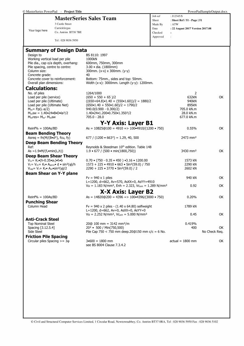
© MasterSeries PowerPad - Project Title PowerPadSampleOutput.docx
Your logo here
MasterSeries Sales Team 3 Castle Street
Carrickfergus
Co. Antrim BT38 7BE
Job ref : J12345/S
Sheet : Sheet Ref / 51 - Page | 51
Made By : ATW
Date : 22 August 2017 Version 2017.08
Checked :
Approved : Tel : 028 9036 5950
© Civil and Structural Computer Services Limited, 1 Circular Road, Newtownabbey, Co. Antrim BT37 0RA, Tel : 028 9036 5950 Fax : 028 9036 5102
Summary of Design Data Design to BS 8110: 1997 Working vertical load per pile 1000kN Pile dia., cap o/a depth, overhang: 600mm, 750mm, 300mm Pile spacing, centre to centre: 3.00 • dia. (1800mm) Column size: 300mm. (x-x) x 300mm. (y-y) Concrete grade: 40 Concrete cover to reinforcement: Bottom: 75mm., sides and top: 50mm. Overall plan dimensions: Width (x-x): 3000mm. Length (y-y): 1200mm.
Calculations: No. of piles 1264/1000 2 Load per pile (service) (650 + 550 + 65 )/2 632kN OK Load per pile (Ultimate) ((650+64.8)•1.40 + (550•1.60))/2 = 1880/2 940kN Load per pile (Ultimate Net) (650•1.40 + 550•1.60)/2 = 1790/2 895kN Myy= Fp(L-a/2) 940.0(0.900 - 0.300/2) 705.0 kN.m Myysw = 1.40•24•B•D•la²/2 1.40•24•1.200•0.750•1.350²/2 28.0 kN.m Myyres= Myy- Myysw 705.0 - 28.0 677.0 kN.m
Y-Y Axis: Layer B1 Reinf% = 100As/BD As = 10B25@100 = 4910 => 100•4910/(1200 • 750) 0.55% OK
Beam Bending Theory Asreq = fn(M/(B•d²), fcu, fy) 677 / (1200 • 663²) = 1.29, 40, 500 2473 mm²
Deep Beam Bending Theory Ref: Reynolds & Steedman 10th edition. Table 148 As =1.9•M/(fy•min(L,h)) 1.9 • 677 / (500 • min(1800,750)) 3430 mm² OK
Deep Beam Shear Theory V1c= K1•(h-0.35•a1)•ft•b 0.70 • (750 - 0.35 • 450 ) •3.16 • 1200.00 1573 kN V1= V1C+ K2• Asprov• d • sin²(φ)/h 1573 + 225 • 4910 • 663 • Sin²(59.0) / 750 2290 kN Vcap= V1+ K2• Asv•sin²(φ)/2 2290 + 225 • 3770 • Sin²(59.0) / 2 2602 kN
Beam Shear on Y-Y plane Fv = 940 x 1 piles 940 kN OK L=1200, d=662, Av=570, AsXX=0, AsYY=4910 Vu = 1.183 N/mm², Enh = 2.323, Vcenh = 1.289 N/mm² 0.92 OK
X-X Axis: Layer B2 Reinf% = 100As/BD As = 14B20@200 = 4396 => 100•4396/(3000 • 750) 0.20% OK
Punching Shear Column Head Fv = 940 x 2 piles - (1.40 x 64.80) selfweight 1789 kN L=1200, d=662, Av=0, AsXX=0, AsYY=0 Vu = 2.252 N/mm², Vcenh = 5.000 N/mm² 0.45 OK
Anti-Crack Steel Top Nominal Steel 20@ 100 mm = 3142 mm²/m 0.419% Spacing [3.12.5.4] 20² • 500 / Min(750,500) 400 OK Side Steel Pile Cap 750 < 750 mm deep.20@150 mm c/c = 6 No. No Check Req.
Friction Pile Spacing Circular piles Spacing >= 3φ 3•600 = 1800 mm actual = 1800 mm OK see BS 8004 Clause 7.3.4.2
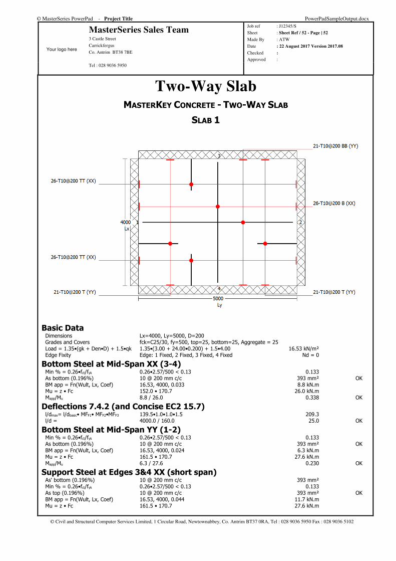
© MasterSeries PowerPad - Project Title PowerPadSampleOutput.docx
Your logo here
MasterSeries Sales Team 3 Castle Street
Carrickfergus
Co. Antrim BT38 7BE
Job ref : J12345/S
Sheet : Sheet Ref / 52 - Page | 52
Made By : ATW
Date : 22 August 2017 Version 2017.08
Checked :
Approved : Tel : 028 9036 5950
© Civil and Structural Computer Services Limited, 1 Circular Road, Newtownabbey, Co. Antrim BT37 0RA, Tel : 028 9036 5950 Fax : 028 9036 5102
Two-Way Slab MASTERKEY CONCRETE - TWO-WAY SLAB
SLAB 1
Basic Data Dimensions Lx=4000, Ly=5000, D=200 Grades and Covers fck=C25/30, fy=500, top=25, bottom=25, Aggregate = 25 Load = 1.35•(gk + Den•D) + 1.5•qk 1.35•(3.00 + 24.00•0.200) + 1.5•4.00 16.53 kN/m² Edge Fixity Edge: 1 Fixed, 2 Fixed, 3 Fixed, 4 Fixed Nd = 0
Bottom Steel at Mid-Span XX (3-4) Min % = 0.26•fct/fyk 0.26•2.57/500 < 0.13 0.133 As bottom (0.196%) 10 @ 200 mm c/c 393 mm² OK BM app = Fn(Wult, Lx, Coef) 16.53, 4000, 0.033 8.8 kN.m Mu = z • Fc 152.0 • 170.7 26.0 kN.m Mapp/Mu 8.8 / 26.0 0.338 OK
Deflections 7.4.2 (and Concise EC2 15.7) l/dmax= l/dbasic• MFF1• MFF2•MFF3 139.5•1.0•1.0•1.5 209.3 l/d = 4000.0 / 160.0 25.0 OK
Bottom Steel at Mid-Span YY (1-2) Min % = 0.26•fct/fyk 0.26•2.57/500 < 0.13 0.133 As bottom (0.196%) 10 @ 200 mm c/c 393 mm² OK BM app = Fn(Wult, Lx, Coef) 16.53, 4000, 0.024 6.3 kN.m Mu = z • Fc 161.5 • 170.7 27.6 kN.m Mapp/Mu 6.3 / 27.6 0.230 OK
Support Steel at Edges 3&4 XX (short span) As' bottom (0.196%) 10 @ 200 mm c/c 393 mm² Min % = 0.26•fct/fyk 0.26•2.57/500 < 0.13 0.133 As top (0.196%) 10 @ 200 mm c/c 393 mm² OK BM app = Fn(Wult, Lx, Coef) 16.53, 4000, 0.044 11.7 kN.m Mu = z • Fc 161.5 • 170.7 27.6 kN.m
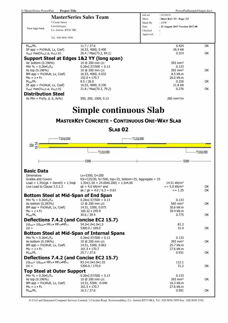
© MasterSeries PowerPad - Project Title PowerPadSampleOutput.docx
Your logo here
MasterSeries Sales Team 3 Castle Street
Carrickfergus
Co. Antrim BT38 7BE
Job ref : J12345/S
Sheet : Sheet Ref / 53 - Page | 53
Made By : ATW
Date : 22 August 2017 Version 2017.08
Checked :
Approved : Tel : 028 9036 5950
© Civil and Structural Computer Services Limited, 1 Circular Road, Newtownabbey, Co. Antrim BT37 0RA, Tel : 028 9036 5950 Fax : 028 9036 5102
Mapp/Mu 11.7 / 27.6 0.424 OK SF app = Fn(Wult, Lx, Coef) 16.53, 4000, 0.400 26.4 kN Vapp/ max(VRd,c.a, VRd,c.b) 26.4 / Max(73.2, 84.1) 0.314 OK
Support Steel at Edges 1&2 YY (long span) As' bottom (0.196%) 10 @ 200 mm c/c 393 mm² Min % = 0.26•fct/fyk 0.26•2.57/500 < 0.13 0.133 As top (0.196%) 10 @ 200 mm c/c 393 mm² OK BM app = Fn(Wult, Lx, Coef) 16.53, 4000, 0.032 8.5 kN.m Mu = z • Fc 152.0 • 170.7 26.0 kN.m Mapp/Mu 8.5 / 26.0 0.326 OK SF app = Fn(Wult, Lx, Coef) 16.53, 4000, 0.330 21.8 kN Vapp/ max(VRd,c.a, VRd,c.b) 21.8 / Max(70.3, 79.2) 0.276 OK
Distribution Steel As Min = Fn(fy, d, b, As%) 500, 200, 1000, 0.13 260 mm²/m
Simple continuous Slab MASTERKEY CONCRETE - CONTINUOUS ONE-WAY SLAB
SLAB 02
Basic Data Dimensions Lx=5300, D=200 Grades and Covers fck=C25/30, fy=500, top=25, bottom=25, Aggregate = 25 Load = 1.35•(gk + Den•D) + 1.5•qk 1.35•(1.50 + 24.00•0.200) + 1.5•4.00 14.51 kN/m² Live Load to Clause 3.5.2.3 qk = 4.0 kN/m² and <= 5.0 kN/m² OK qk / gk = 4.0 / 6.3 = 0.63 <= 1.25 OK
Bottom Steel at Mid-Span of End Span Min % = 0.26•fct/fyk 0.26•2.57/500 < 0.13 0.133 As bottom (0.283%) 12 @ 200 mm c/c 565 mm² OK BM app = Fn(Wult, Lx, Coef) 14.51, 5300, 0.075 30.6 kN.m Mu = z • Fc 160.32 • 245.9 39.4 kN.m Mapp/Mu 30.6 / 39.4 0.775 OK
Deflections 7.4.2 (and Concise EC2 15.7) l/dmax= l/dbasic• MFF1• MFF2•MFF3 54.2•1.0•1.0•1.5 81.3 l/d = 5300.0 / 169.0 31.4 OK
Bottom Steel at Mid-Span of Internal Spans Min % = 0.26•fct/fyk 0.26•2.57/500 < 0.13 0.133 As bottom (0.196%) 10 @ 200 mm c/c 393 mm² OK BM app = Fn(Wult, Lx, Coef) 14.51, 5300, 0.063 25.7 kN.m Mu = z • Fc 161.5 • 170.7 27.6 kN.m Mapp/Mu 25.7 / 27.6 0.931 OK
Deflections 7.4.2 (and Concise EC2 15.7) l/dmax= l/dbasic• MFF1• MFF2•MFF3 83.1•1.0•1.0•1.35 112.1 l/d = 5300.0 / 170.0 31.2 OK
Top Steel at Outer Support Min % = 0.26•fct/fyk 0.26•2.57/500 < 0.13 0.133 As top (0.196%) 10 @ 200 mm c/c 393 mm² OK BM app = Fn(Wult, Lx, Coef) 14.51, 5300, -0.040 16.3 kN.m Mu = z • Fc 161.5 • 170.7 27.6 kN.m Mapp/Mu 16.3 / 27.6 0.591 OK
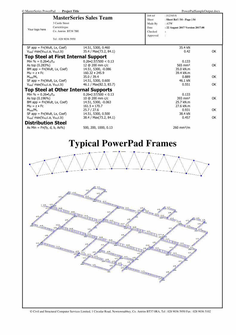
© MasterSeries PowerPad - Project Title PowerPadSampleOutput.docx
Your logo here
MasterSeries Sales Team 3 Castle Street
Carrickfergus
Co. Antrim BT38 7BE
Job ref : J12345/S
Sheet : Sheet Ref / 54 - Page | 54
Made By : ATW
Date : 22 August 2017 Version 2017.08
Checked :
Approved : Tel : 028 9036 5950
© Civil and Structural Computer Services Limited, 1 Circular Road, Newtownabbey, Co. Antrim BT37 0RA, Tel : 028 9036 5950 Fax : 028 9036 5102
SF app = Fn(Wult, Lx, Coef) 14.51, 5300, 0.460 35.4 kN Vapp/ max(VRd,c.a, VRd,c.b) 35.4 / Max(73.2, 84.1) 0.42 OK
Top Steel at First Internal Support Min % = 0.26•fct/fyk 0.26•2.57/500 < 0.13 0.133 As top (0.283%) 12 @ 200 mm c/c 565 mm² OK BM app = Fn(Wult, Lx, Coef) 14.51, 5300, -0.086 35.0 kN.m Mu = z • Fc 160.32 • 245.9 39.4 kN.m Mapp/Mu 35.0 / 39.4 0.889 OK SF app = Fn(Wult, Lx, Coef) 14.51, 5300, 0.600 46.1 kN Vapp/ max(VRd,c.a, VRd,c.b) 46.1 / Max(82.3, 83.7) 0.551 OK
Top Steel at Other Internal Supports Min % = 0.26•fct/fyk 0.26•2.57/500 < 0.13 0.133 As top (0.196%) 10 @ 200 mm c/c 393 mm² OK BM app = Fn(Wult, Lx, Coef) 14.51, 5300, -0.063 25.7 kN.m Mu = z • Fc 161.5 • 170.7 27.6 kN.m Mapp/Mu 25.7 / 27.6 0.931 OK SF app = Fn(Wult, Lx, Coef) 14.51, 5300, 0.500 38.4 kN Vapp/ max(VRd,c.a, VRd,c.b) 38.4 / Max(73.2, 84.1) 0.457 OK
Distribution Steel As Min = Fn(fy, d, b, As%) 500, 200, 1000, 0.13 260 mm²/m
Typical PowerPad Frames
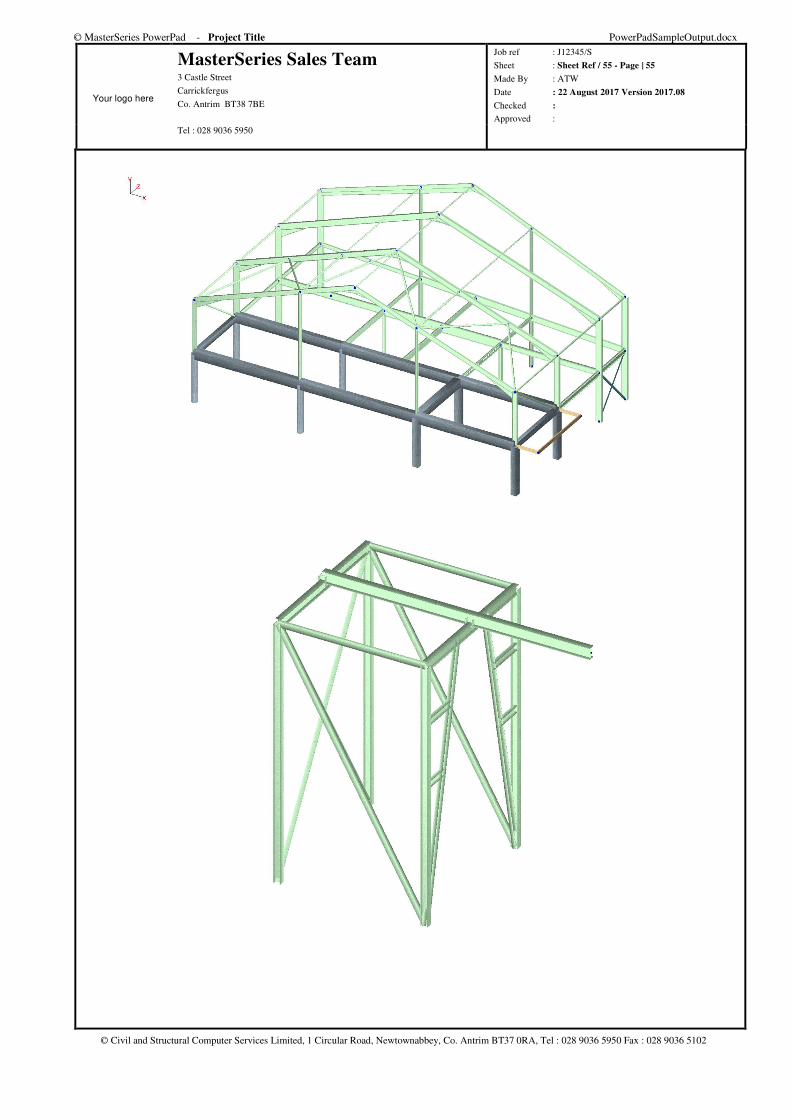
© MasterSeries PowerPad - Project Title PowerPadSampleOutput.docx
Your logo here
MasterSeries Sales Team 3 Castle Street
Carrickfergus
Co. Antrim BT38 7BE
Job ref : J12345/S
Sheet : Sheet Ref / 55 - Page | 55
Made By : ATW
Date : 22 August 2017 Version 2017.08
Checked :
Approved : Tel : 028 9036 5950
© Civil and Structural Computer Services Limited, 1 Circular Road, Newtownabbey, Co. Antrim BT37 0RA, Tel : 028 9036 5950 Fax : 028 9036 5102
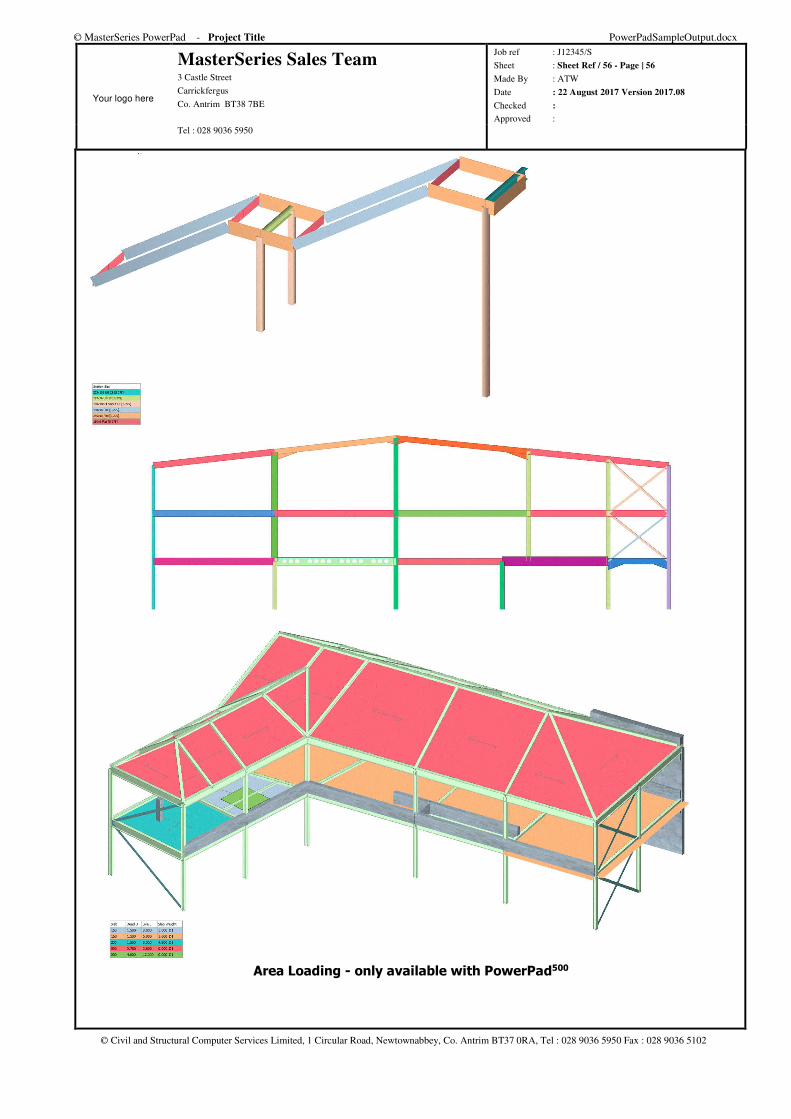
© MasterSeries PowerPad - Project Title PowerPadSampleOutput.docx
Your logo here
MasterSeries Sales Team 3 Castle Street
Carrickfergus
Co. Antrim BT38 7BE
Job ref : J12345/S
Sheet : Sheet Ref / 56 - Page | 56
Made By : ATW
Date : 22 August 2017 Version 2017.08
Checked :
Approved : Tel : 028 9036 5950
© Civil and Structural Computer Services Limited, 1 Circular Road, Newtownabbey, Co. Antrim BT37 0RA, Tel : 028 9036 5950 Fax : 028 9036 5102
Area Loading - only available with PowerPad500