STORAGE OSCILLOSCOPE - tradebit · 12327 freeway corporation 9301 allen drive cleveland, oh 44125...
48
STORAGE OSCILLOSCOPE WITH OPTIONS SERVICE
Transcript of STORAGE OSCILLOSCOPE - tradebit · 12327 freeway corporation 9301 allen drive cleveland, oh 44125...
STORAGEOSCILLOSCOPE
WITH OPTIONSSERVICE

ιι ιιιιιιιιιιι1 TEKTRONIX1111
Tekt ronix, Inc .P.O . Box 500Beave rton, Oregon 97005
Serial NumberιINSTRUCTION MANUALι
070-1653-01
First Printing JUNE 1974
WARRANTYTektronix warrants that this product is free from defects in materi αIsand workmanship. Thewarranty period is one (,1) year from thedateof sh ipment. -Tektronix will, at its optio n, repai r o r replace theprod uct if Tektronix determines it is defective within the warrantyperiod and it it is ret urned , freight prepaid ,, to α service centerdesig nated by Tektronix .
Tektronix is not obligated to furnish service u n der this warranty
α.
to repair damage resulting from attempts by personnel othert han Tektronix representatives to install, repair, o r service theproduct
b . , to repair d amage 'resulting fromimproper-use or fromconnecting the prod u ct to incompati ble equipment;
c.
if personnel oth er than Tektronix representatives modify thehardware or software .
There is no Implied warranty of tPtness for α particular purpose.Tektronix Is` not Ι 1αbΙe for consequential damages.
Copyright @1974, 1975 Tektronix, I nc. All rights reserved .Contents of this publication mayhot be reprod uced ί η anyform without. the written permission of rektroηix; l η:ο .
Products of 'Tektronix, Inc. and its subsidia ries arecovered' by U.S . and foreign patents and/or : pendingpatents .
TEKTRONIX, ΤEΚ, SCOPE-MOBILE, and ..
are reg- .isfered trade,marks . of Tektronix, Inc..
Pr ΐnted .
:in . U.S Α .
5pe.cif catiaη
and' - price
change'privileges are reserved .
TABLE OF CONTENTSSECTIO N 1
SPECI F ICATIO N
Page
SECTION 4
MAI NTEN A N CE
PageI n t roduction
1-1
Introduction4-1Electrical Ch aracteristics
1-1
Ca b inet Removal
4-1Envi ronmental Characteristics
1-10
PREVENTIVE MAI NTEN AN CE
4-1Physical Cha racte r istics
1-11
Gen eral
4-1Standard Accessories
1-11
Clean ing
4-1Visu al Inspection
4-2Lub r icatio n4-2
SECTIO N 2
OPERATI NG I NSTRUCTIONS
Semico nductor Checks
4-2R
Operati ng Voltage
2_ η
ecali bration
4-3CORRECTIVE M AINTENAN CE
4-3Safety I n formation
2-1
General
4-3Nominal L i n e Voltage Range
2-1
Obtaining Replacemen t Parts
4-3Options
2-2
Recalibr ation After Repair
4-3CONTR O LS, CONNECTO RS A N D
I nstru men t Repackagi ng
4-3INDICATO RS
2-2
Solde r i ng Techn iques
4-3V ertical
2-2
Component Replacement
4-4Display and Storage
2-4
Circ u it Board Replacemen t
4-4Trigger
2-5
Low Voltage Power Transforme rH orizontal and Power
2-6
Rep lacement
4-7Rear Panel
2-7
HV Multi p lie r & HV Transfo rme rSide Pan el
2-8
Rep lacemen t
4-7Ρ6062Α 10x-1X Probe
2-8
CRT Replacemen t
4-7BASIC DISPLAYS
2-9Normal Sweep Display
2-9
SECTION 5
CAL IBRATIO NMagnified Sweep Display
2-9Delayed Sweep Disp lay
2_g
Introduction5-1Mixed Sweep Dis play
2-10
Test Equipmen t Required5-2
Χ -Υ Display
2_ηρ
Cabinet Removal
5-5
Si ngle Sweep Disp lay
2-10
Α . Power Supplies and Calibrato r5-6
STORAG E DISPLAYS
2-10
Β . Dis p lay and Ζ-Axis
5-8
Storage
2_ηρ
C. Vertical
5-10
Save Storage
2_ ηη
D. Trigger
5-22
Save Ra ndom Events
2-11
Ε . DM-Series Digital M ultimeters
5-33
Multiple Trace Storage
2-11
F . H o r izon tal
5-34
Care of Storage Screen
2-11
G . Storage
5-45
PERFORMANCE CHECK
2_ η 2
Η . Χ -Υ Display, Ζ-Axis and Gate Outp uts 5-52
Pu rpose
2-12
SECTION 6
ELECTR ICAL REPLACEA BLE PARTS LISTRecommended Eq uipme n t
2-12PERFORMANCE CHECK PROC EDURE 2-14
Parts Orderi n g I n formation
6-1Α . P reli m i na ry Proced u re
2-14
Special Notes and Sym bols
6-1Β . Vertical
2-14
Abbreviatio ns
6-1C. T rigger
2-16
Cross I ndex MFG Code Number toD . D M-Se r ies Digital Multimete r s
2-22
Manufact ur e r6-2Ε . Horizon tal
2-22
Electrical Parts L ist
6-3F. Storage
2-28G.X-Y Display, Z-Axis and Gate Outputs
2-30
OPTION INFORMATION
SECTION 7
DIAGRAMS & CI RCU IT BOAR DI LLU STRATIO NS
S E CTION 3
CIRCU IT DESCR I PTIONIntroduction
3_ η
ADJUST MENT LOCATIONSDigital Logic
3-1BLOCK DIAGRAM DESCR I PTION3-1
SECTIO N 8
MECH A N ICAL REPLAC EABLE PARTS L ISTVe rtical Sectio n3-1
Parts Orde r i n g I n fo rm ation8-1Ho r izon tal Sectio n3-1
Special Notes and Symbols
8-1Ζ-Axis Amplifier
3-2
Figure and I n dex Nu mbers
8-1Power Section
3-2
I ndentatio n Syste m8-1DETAILE D CIRC U IT DESC R IPTION3-2
Item Name
8-1Vertical Section3-2
Cross Index MFR Cod e Num ber toHorizontal Sectio n3-9
Manufact u rer
8-1Calibrator
3-15
Abbreviatio ns
8-2Low Voltage Power S upply
3-15
Mecha nical P a rts L ist and Figures
8-3Fan Moto r Ci r cuit
3-16
Cabinet and Accesso r iesΖ-Axis-CRT Circuit
3-16Sto rage Circu its
3-19
CHANG E I NF ORMATION
REV . Β , D EC . 1976
464 Service
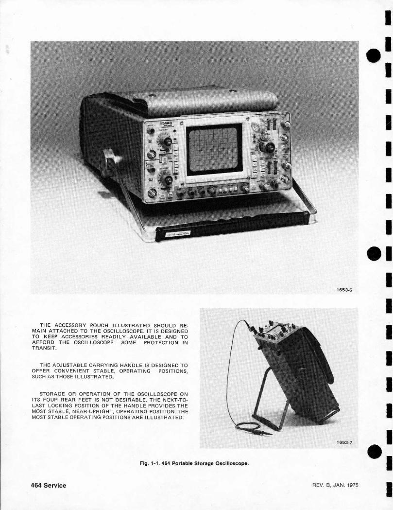
THE ACC ESSO RY POUCH ILLUSTRATED SHOULD RE-MAIN ATTACHED TO THE OSCI LLOSCO PE . I T IS DESIGNE DTO KEEP ACCESSOR I ES READI LY AVAI LABLE AND TOA FFORD THE OSCI LLOSCOPE SOME PROTECTION INTRANSIT .
THE ADJUSTABLE CA RRYING H ANDLE Ι5 DESIGNED TOO FFER CO NVEN I ENT STABLE , OPER ATING POSITIONS,SUCH Α5 THOSE ILLUSTRATED .
STORAG E OR O PERATION O F THE OSCI LLOSCOPE ONITS FOUR REAR FEET IS NOT D ESI R ABLE . THE NEXT-TO-LAST LOCK I N G POSITION OF THE HAN D LE PROV ID ES THEMOST STABLE, NEAR-UPR IG HT, OPERATING POSITIO N . THEMOST STABLE OPERATING POSITIONS ARE I LLU STR ATED .
464 Service
Fig . 1-1 . 464 Portable Storage Oscilloscope .
1653-6
1653-7
ιι ι
ιιιιιιι
ιιιιιιιιιι ι
REV . Β , JAN . 1975
1
ι ιιι
Deflection Factor CalibratedRange
'
U ncalibrated (VAR VOLTS/DIV)Ran ge
ιLow F requency L i n earity
ιDeflection Factor Accuracy
Bandwidth
I
REV. Β , JAN. 1975
SPECI FICATION
Section 1-464 Service
'
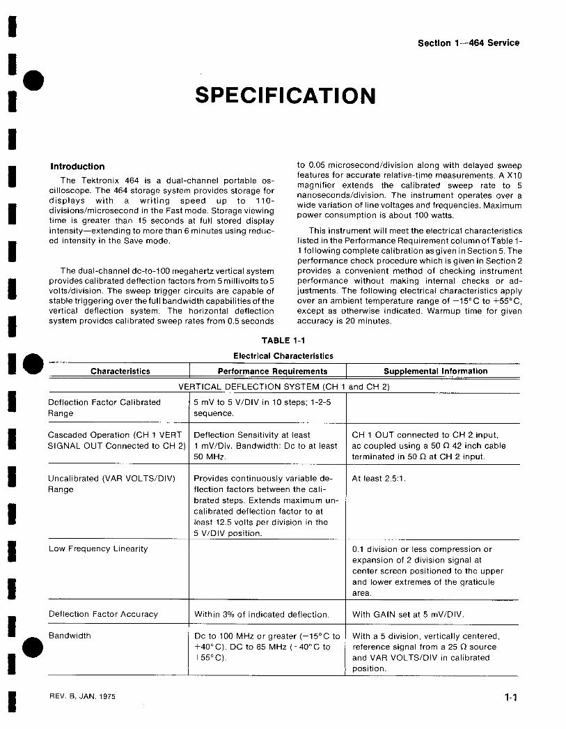
Introduction
to 0.05 microsecond/division along with delayed sweepfeatures for accurate relative-time measurements . Α Χ10
The Tektronix 464 is α dual-cha nnel portable os-i
magnifier extends the calibrated sweep rate to 5
displays
The 464 storage system provides storage for
na noseco nds/division. The instrument operates over αis
with
α
writing
speed
up
to
110-
wide variation of line voltages and frequencies . Maximumdivisions/microsecond in the Fast mode . Storage viewin g
power consumption is about 100 watts.time is greater than 15 seconds at full stored displayintensity-extend i n g to more than 6 minutes using reduc-
This instrument will meet the electrical characteristics'
ed intensity in th e Save mode.
listed in the Performance Requirement column of Table 1-1 following com plete calibratio n as given in Section 5. Theperformance check p rocedure wh ich is given in Section 2
T h e dual-ch annel dc-to-100 megah ertz vertical system
p rovides α conven ient meth od of checki ng i nstrumentprovides calibrated deflection factors from 5 millivolts to 5
performance without
maki ng
internal
checks
or ad-'
volts/divisio n . The sweep trigger circuits are capable of
j ustments . The followi ng electrical characteristics applystable triggeri ng over the full bandwidth ca pabilities of the
over an ambient tem perature range of -15°C to +55°C,vertical deflection system . The horizontal deflection
exce pt as otherwise indicated . Warm up time for givensystem provides calibrated sweep rates from 0.5 seconds
accuracy is 20 min utes .
TABLE 1-1
Electrical Characteristics
Characteristics
Performance Requirements
Supplemental Information
VERTICAL DEFLECTIO N SYSTEM (C H 1 and CH 2)
5 mV to 5 V/DI V in 10 steps; 1-2-5sequence .
'
Cascaded Operation (CH 1 VERT
Deflection Sensitivity at least
CH 1 OUT connected to CH 2 inp ut,SIGNAL OUT Connected to CH 2)
1 mV/Div . Ban dwidth: Dc to at least
ac coupled u si ng α 50 Ω 42 inch cable50 MHz.
terminated in 50 Ω at CH 2 input.
P rovides conti nuously variable de-flection factors between the cali-brated steps. Extends maximum υη-calibrated d eflectio n factor to atleast 12 .5 volts per divisio n in the5 V/DIV position.
W it h in 3ο/ο of i nd icated deflection .
At least 2.5 :1 .
0.1 divisio n or less compression orexpansion of 2 division signal atcenter screen positioned to the upperand lower extremes of th e graticulearea .
W it h GAIN set at 5 mV/DIV.
Dc to 100 MHz or greater (-15°C to
W it h α 5 divisio n , vertically centered,+40°C) . DC to 85 MHz (+40°C to
reference signal from α 25 Ω source+55°C) .
and VAR VOLTS/DIV in calibratedpositio n.
Replaceable Mechanical Parts-464 Service
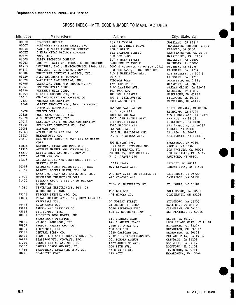
CROSS IND EX-MFR. COD E NUMBER TO MA NUFACT URER
Mfr . Cod e
Manufacturer
Add ress
City, State, ZipΟΟΟΒΚ
STAUFFER SUPPLY
105 5Ε TAYLOR
PORTLAND, OR 97214OOOCY
NORTHWEST FASTENER SALES, INC .
7923 SW CIRRUS DRIVE
BEAVERTON, OREGON 97005OOODX
KADEE QUALITY PRODUCTS COMPANY
720 S GRAPE
MEDFORD, OR 97501ΟΟΟΕΧ
Ο 'HARA METAL PRODUCT COMPANY
542 ΒΑΑΝΝΑΝ STREET
SAN FRANCISCO, CA 9410700779
AMP, INC .
Ρ 0 BOX 3608
HARRISBURG, PA 1710501009
ALLEN PRODUCTS COMPANY
117 Ν MAIN STREET
BROCKTON, MA 0240301963
CHERRY ELECTRICAL PRODUCTS CORPORATION
3600 SUNSET AVENUE
WAUKEGAN, IL 6008504713
MOTOROLA, INC ., SEMICONDUCTOR PROD . DIV . 5005 Ε MCDOWELL RD,PO BOX 20923 PHOENIX, AZ 8503604811
PRECISION COIL SPRING COMPANY
Ρ 0 BOX 5450, 10107 ROSE ST .
EL ΜΟΝΤΕ , CA 9173405006
TWENTIETH CENTURY PLASTICS, INC .
415 Ε WASHINGTON BLVD .
LOS ANGELES, CA 9001505129
KILO ENGINEERING COMPANY
2015 D
LA VERNE, CA 9175005820
WAKEFIELD ENGINEERING, INC .
AUDUBON ROAD
WAKEFIELD, MA 0188007700
TECHNICAL WIRE AND PRODUCTS, INC .
129 DERMODY ST .
CRANFORD, NJ 0701608261
SPECTRA-STRIP CORP .
7100 LAMPSON AVE .
GARDEN GROVE, CA 9264208530
RELIANCE MICA CORP .
342-39TH ST .
BROOKLYN, NY 1123209353
C AND Κ COMPONENTS, INC .
103 MORSE STREET
WATE RTOWN, MA 0217212014
CHICAGO RIVET AND MACHINE CO .
950 S . 25TH AVENUE
BELLWOOD, IL 6010412327
FREEWAY CORPORATION
9301 ALLEN DRIVE
CLEVELAND, OH 4412512360
ALBANY PRODUCTS CO., DIV. OF PNEUMODYNAMICS CORPORATION
145 WOODWARD AVENUE
SOUTH NORWALK, CT 0658616428
BELDEN CORP .
Ρ . 0 . BOX 1331
RICHMOND, IN 4737422526
BERG ELECTRONICS, INC .
YOUK EXPRESSWAY
NEW CUMBERLAND, PA 1707022670
G.M. NAMEPLATE, INC .
2040 15TH AVENUE WEST
SEATTLE, WA 9811924011
ELECTRONIZED CHEMICALS CORPORATION
S BEDFORD STREET
BURLINGTON, MA 0180324931
SPECIALTY CONNECTOR CO., INC .
3560 MADISON AVE .
INDIANAPOLIS, IN 4622725088
SIEMENS CORP .
186 WOOD AVE . S
I SELIN, NJ 0883027143
ATLAS SPRING AND MFG. CO .
1805 Ν . SPAULDING AVE .
CHICAGO, IL 6064728520
ΗΕΥΜΑΝ MFG. CO .
147 Ν . MICHIGAN AVE .
KENILWORTH, NJ 0703328817
CAL-ΜΕΤΕΧ CORP ., SUBSIDIARY OF ΜΕΤΕΧCORP .
509 HINDRY AVE .
INGLEWOOD, CA 9030142838
NATIONAL RIVET AND MFG . CO .
1-21 EAST JEFFERSON ST .
WAUPUN, WI 5396351316
ANGELUS WASHER AND STAMPING CO .
1411 E SPERANZA ST .
LOS ANGELES, CA 9002355210
GETTIG ENG . AND MFG . COMPANY
PO BOX 85, OFF ROUTE 45
SPRING MILLS, PA 1687570276
ALLEN MFG . CO .
Ρ . 0 . DRAWER 570
HARTFORD, CT 0610170278
ALLIED STEEL AND CONVEYORS, DIV . OFS PARTON CORP .
17333 HEALY
DETROIT, MI 4821270318
ALLMETAL SCREW PRODUCTS CO., INC .
821 STEWART AVE .
GARDEN C ITY, NY 1153071159
BRISTOL SOCKET SCREW, DIV . OFAMERICAN CHAIN AND CABLE CO ., INC .
Ρ 0 BOX 2244, 40 BRISTOL ST.
WATERBURY, CT 0672071279
CAMBRIDGE THERMIONIC CORP .
445 CONCORD AVE .
CAMBRIDGE, ΜΑ 0213871400
BUSSMAN MFG ., DIVISION OF MCGRAW-EDISON CO .
2536 W . UNIVE RSITY ST .
ST. LOUIS, MO 6310771590
CENTRALAB ELECTRONICS, DIV. OFGLOBE-UNION, INC .
Ρ 0 BOX 858
FORT DODGE, IA 5050173743
FISCHER SPECIAL MFG . CO .
446 MORGAN ST.
CINCINNATI, OH 4520673803
TEXAS INSTRUMENTS, INC ., METALLURGICALMATE RIALS DIV .
34 FOREST STREET
ATTLEBORO, MA 0270374445
ΗΟLΟ-ΚΑΟΜΕ CO .
31 BROOK ST. WEST
HARTFORD, CT 0611075497
LAMSON AND SESSIONS CO .
5000 TIEDEMAN ROAD
CLEVELAND, OH 4414475915
LITTELFUSE, INC .
800 Ε . NORTHWEST ΗWΥ
DES PLAINES, IL 6001678189
ILLINOIS TOOL WORKS, INC .SHAKEPROOF DIVISION
ST . CHARLES ROAD
ELGIN, IL 6012079136
WALDES, KOHINOOR , INC .
47-16 AUSTEL PLACE
LONG I SLAND CITY, NY 1110179807
WROUGHT WASHER MFG . CO .
2100 S . 0 BAY ST .
MILWAUKEE, WI 5320780009
TEKTRONIX, INC .
Ρ 0 BOX 500
BEAVERTON, OR 9707783385
CENTRAL SCREW CO .
2530 CRESCENT DR .
BROADVIEW , IL 6015386445
PENN FIBRE AND SPECIALTY CO., INC .
2032 Ε . WESTMORELAND ST .
PHILADELPHIA, PA 1913486928
SEASTROM MFG . COMPANY, INC .
701 SONORA AVENUE
GLENDALE, CA 9120191260
CONNOR SPRING AND MFG. CO .
1729 JUNCTION AVE .
SAN JOSE, CA 9511293907
CAMCAR SCREW AND MFG . CO .
600 18TH AVE .
ROCKFORD, IL 6110197464
INDUSTRIAL RETAINING RING CO .
57 CORDIER ST .
IRVINGTON, NJ 0711198291
SEALECTRO CORP .
225 ΗΟΥΤ
MAMARONECK, NY 10544
ι
ι ιιιιi
1
i
1
1
1
1
1
1
1
18-2
REV Ε, FEB 1980
1
ιF ig . &
"
In dex
Te ktronix
Serial/ Model No .
MfrNo.
P art No .
Eff
Dscont
Qty 1 2 3 4 5
Name & Desc ι i n tio nCo de
Mfr Part Number
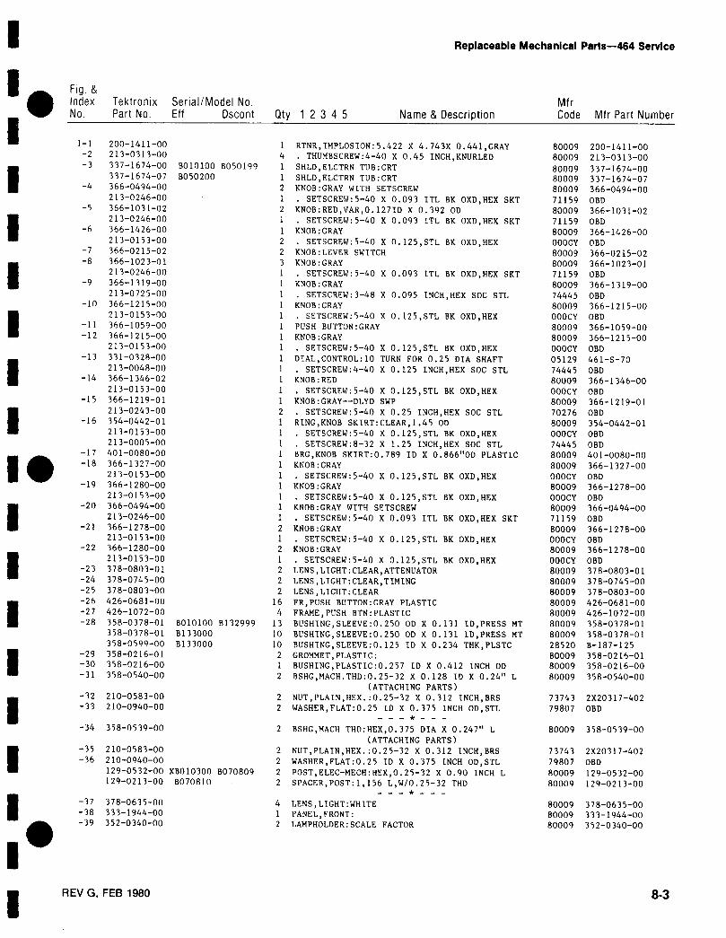
1-1
200-1411-00
1 RTNR,IMPLOS ION :5 .422 Χ 4 .743Χ 0 .441,GRAY
80009 200-1411-00-2
213-0 313-00
4 . THUMBSCREW :4-40 Χ 0 .45 INCH, KNURLED
80009 213-0313-00-3
337-1674-00 Β010100 Β050 199
1 SHLD, ELCTRN TUB :CRT
80009 337-1674-00337-1674-07 Β050200
1 SHLD, ELCTRN TUB :CRT
80009 337-1674-07-4
366-0494-00
2 KNOB :GRAY WITH SET SCREW
80009 366-0494-00213- π 246-00
1 . SETSCREW:5-40 Χ 0 .093 ITL 8Κ OXD ,HEX SKT
71159 OBD-5
366-1031-02
2 KNOB : RED , VAR ,0 .1271D Χ 0 .392 OD
80009 366-1031-0 2213-0246-ΠΠ
1 . SETSCREW:5-40 Χ 0 .093 ITL ΒΚ OXD ,HEX SKT
71159 OBD-6 366-1426-001 KNOB :GRAY
80009 366-1426-00213-0153-00
2 . SETSCREW:5-40 Χ Π .125,STL ΒΚ ΠΧD , ΗΕΧ
OOOCY OBD-7
366-0215-02
2 KNOB :LEVER SWITCH80009 366-0215-02-8 366-1023-0 1
3 KNOB :GRAY
80009 366-1 0 23-01213-0246-ΟΠ
1 . SETSCREW :5-40 Χ 0 .093 ITL ΒΚ OXD ,HEX SKT
71159 OBD-9 366-1319-001 KNOB:GRAY
80009 366-1319-00213-0725-ΛΟ
1 . SETSC REW :3-48 Χ 0 .095 INCH,HEX SOC STL
74445 OBD-10 366-1215-001 KNOB :GRAY
80009 366-1215-00213-0153-ΠΟ
1 . SETSCREW :5-4Π Χ Π .125,STL ΒΚ OXD,HEX
OOOCY OBD-11 366-1059-0 01 PUSH BUTTON :GRAY
80009 366-1 059-00-12 366-1215-00
1 KNOB:GRAY
80009 366-1215-00213-0153-00
1 . SET SCREW :5-40 Χ n .125,STL ΒΚ OXD,HE X
OOOCY OBD-13 331-032 Α-00
1 DI AL,CONTROL:10 TURN FOR 0 .25 DIA SHAFT05129 461-S-70213- Π048-0Π
1 . SETSCREW :4-4Π Χ 0 .125 INCH,HEX SOC STL
74445 OBD-14 366-1346-02
1 KNOB :RED
80009 366-1346-00213-0153-00
1 . SETSCREW :5-40 Χ Λ .125,STL ΒΚ OXD,HEX
OOOCY OBD-15 366-1219-01
1 KNOB:GRAY--DLYD SWP
80009 366-1219-01213-0243-00
2 . SETSCREW :5-4n Χ 0 .25 INCH ,HEX SOC STL
70276 OBD-16 354-0442-01
1 RING, KNOB SKIRT :CLEAR ,1 .45 OD
80009 354-0442-01213- Λ 153-00
1 . SETSCREW:5-40 Χ 0 .125,STL ΒΚ OXD ,HEX
OOOCY OBD213-0005-ΠΟ
1 . SETSCREW:8-32 Χ 1 .25 INCH,HEX SOC STL
74445 OBD"
-17 401-Οπ10-00
1 BRG, KNOB SKIRT :0 .789 ID Χ 0 .866"OD PLASTIC
80009 401-0080-00-18 366-1327-00
1 KNOB :GRAY
80009 366-1327-00213-0153-00
1 . SETSC REW :5-40 Χ 0 .125,STL ΒΚ OXD ,HEX
ΟΠΟCΥ OBD-19 366-1280-00
1 KNOB:GRAY
80009 366-1278-00213-0153-00
1 . SETSCREW :5-40 Χ 0 .125,STL ΒΚ OXD ,HEX
OOOCY OBD-20 366-0494-00
1 KNnB :GRAY WITH SETSCREW
80009 366-0494-00213-Λ246-00
1 . SETSCREW :5-4 Π Χ 0 .093 ITL ΒΚ OXD,HEX SKT
71159 OBD-21 366-1278-00
2 KNOB :GRAY
80009 366-1278-00213-0153-00
1 . SET SCREW :5-4Π Χ 0 .125,STL ΒΚ OXD,HEX
ΠΠΟCΥ OBD-22 366-1280-00
2 KNOB :GRAY
80009 366-1278-00213-0153-00
1 . SETSCREW :5-4Π Χ 0 .125,S TL ΒΚ OXD,HEX
OOOCY OBD-23 378-08Π3-01
2 LENS, LIGHT :CLEAR,ATTENUATOR
80009 378-08π3-01-24 378-0745-00
2 LENS, LIGHT :CLEAR,TIMING
80009 378-0745-0Π-25 378-0803-0 02 LENS, LIGHT :CLEAR
80009 378-0803-00-26 426- Π 681-ΟΛ
16 FR,PUSH BUTTON :GRAY PLASTIC
80009 426-0681-Οπ-27 426-1072-00
4 FRAME,PUSH BTN :PLASTI C
80009 426-1072-00-28 358-0378-01 Β010100 Β 132999
13 BUSHING,SLEEVE : 0 .250 OD Χ 0.131 ID,PRE SS MT
80009 358-0378-0 1358-0378-01 Β133000
10 BUSHING,SLEEVE :0 .250 OD Χ 0 .131 ID,PRE SS MT
80009 358-0378-01311-0519-00 Β 133000
10 BU SH ING,SLEEVE :0 .125 ID Χ 0,234 THK, PLSTC
21120 8-187- 1 25-29 358-0216-01
2 GROMMET,PLASTIC :
80009 358-0216-01-30 358-0216-001 BUSH ING, PLASTIC :0 .257 ID Χ 0 .412 INCH OD
80009 358-0216-00-31 358-0540-002 BSHG,MACH . THD : 0 .25-32 Χ 0 .128 I D Χ 0 .24" L
80009 358-0540-00(ATTACH ING PARTS)
-32 210-0583-00
2 ΝυΤ , ΡLΑΙΝ , ΗεΧ . :0 .25-32 Χ 0 .312 INCH, BRS
73743 2Χ20317-402-33 210-0940-00
2 WASHE R , FLAT:0 .25 ID Χ 0 .375 INCH OD,STL
79807 OBD
-34 358-Π539-00
2 BS HG, MACH THD : HEX. ,0 .375 DIA Χ 0 .247" L
80009 358-0539-00(ATTACHING PARTS)
-35 210-0583-002 NUT , PLAIN ,HEX . :0 .25-32 Χ 0 .312 INCH, BRS
73743 2Χ 20317-402-36 210-0940-00
2 WASHER , FLAT :0 .25 ID Χ 0 .375 INCH OD ,STL
79807 OBD129-0532-00 ΧΒπ 10300 Β070809
2 PnST , ELEC-ΜΕCΗ : ΗεΧ ,0 .25-32 Χ 0 .90 INCH L
80009 129-0532-00129-0213-00 Β070810
2 SPACER , POST :1,156 L ,W/0 .25-32 THD
80009 129-02 1 3-00
-37 378-0635-004 LENS, LIGHT : WHITE
.'
80009 378-0635-00-38 333-1944-00
1 PANEL,F RΠNT :
80009 333-1944-00-39 352-0340-00
2 LAMPHOLDER :SCALE FACTOR
80009 352-0340-00
I
ι
Replaceable Mechanical Parts-464 Service
I
REV G, FEB 1980
8_3

TEKTRONIX
DΜ43 "DM40DIGITAL
ινιυιτιινιετEΑSERVICE
INSTRUCTIO N MANUALTektronix, Inc .Ρ .Ο . Box 500Beaverton, Oregon 97005
Serial Number
070-1779-00
F irst P rinti n g JULY 1974
All T EKTR ON IX instruments are warranted againstdefective materials and work manship for one year .Any questions with respect to th e warranty shouldbeta ken up with your TEKTR ON IX F ield E ngineer orrepresentative .
All requests for re pairs an d replacement partssh ould be directed to the TEKTRONIX Field Officeor rep resentative in your area . This will assure youthe fastest p ossible service . Please include th ein strument Type Number or Part Number and Se ria lNumber with all requests for parts or service .
Specifications and price change privileges reserved.
Copy righ t c 1974 by Tektronix, Inc ., Beaverton,Oregon . Printed in the United States of America . Allrig h ts reserved. Co ntents of this publication may notbe re p roduced in any form without permission ofTek tronix, Inc .
U .S.A . and fo reig n TEK T R ON IX p roducts coveredby U.S . and foreig n pate n ts and/or patents pending .
TEKT R O N IX is α registered tra demark of Tektronix,Ι
WA RR ANTY
TABLE O F CO NTENTS
L IST O F I LLUSTRATIONS
ivL IST O F TABLES
ν
SECTION 1
SPECI FICATIONIntroduction
1-1ELECTRICA L1-1
Dc Voltage
1-1Rejection Ratio
1-1Recycle Time
1-1Response Time
1-1Maximum Safe Input Voltage
1-1Common Floating Voltage
1-1Resistance
1-1Temperature (With Ρ6430 Probe) DM43 Only
1-1Time (Differential) Delay
1-2ENVIRONMENTAL
1-2Temperature
1-2Altitude
1-2Humid ity
1-2Vibration
1-2Shock1-2
PHYSICA L1-2Finish1-2
ACCESSORIES
1-2Standard1-2Optional 1-2
SECTIO N 2
OPERATING INFORMATIONIntroduction
2-1
CO NTROLS AND CONNECTORS
2-1
RANGE Switch2-1
FUNCTION Switch2-1
ZERO Pushbutton
2-1
Input Connectors
2-1
Probe Connector (DM43 Only)
2-1
DM43-DM40 Service
PAG E

DM43-DM40 Service
TABLE OF CONTENTS(cont .)
PAGE
SECTION 3
CIRCUIT DESCRIPTIONIntroduction
3-1Digital Logic
3-1DETAILED DESCRIPTION
3-1Volts Range Switching
3-1Ohms Converter
3-1Temperature Converter
3-3Time Converter
3-3Analog-Digital Voltmeter
3-3Auto-Zero Interval
3-4Measure Interval (see Fig . 3-3)
3-4Power Supply
3-7
SECTION 4
MAINTENANCECIRCUIT BOARD REMOVAL
4-1Main Board
4-1Readout Board
4-1Power-Supply Board
4-1
SECTION 5
PERFORMANCE CHECK/CALIBRATIONCalibration Interval
5-1Performance Check
5-1Calibration Procedure
5-1Procedure Arrangement
5-1TEST EQUIPMENT REQUIRED
5-1(For DM43-DM40 AND 464-465-466)
Calibration Equipment Alternatives
5-1DM43-DM40 PERFORMANCE CHECK
5-4INDEX TO PERFORMANCE CHECK
5-4PROCEDURE
5-4HORIZONTAL SYSTEM PERFORMANCE CHECK
5-7DM43-DM40 CALIBRATION
5-14INDEX TO CALIBRATION PROCEDURE
5-14PROCEDURE
5-14464-465-466 HORIZONTAL SYSTEM CALIBRATION PROCEDURE
5-17
TABLE 0 F C 0ΝΤΕ ΝΤS(cont .)
PAGE
DM AND 475 HORIZONTA L SYSTEM PERFORMANCE CHECK/
5-25CA L I BR ATION
ADDITIONAL TEST EQUI PMENT REQUI RE D FO R 475
5-25PERFORMANCE CHECK
5-26I NDEX TO PERFORMANCE CHECK
5-26Control Settings :
5-26CALI BRATION5-31
INDEX TO CALI BRATION PROC EDURE
5-31PR OCEDURE
5-31
SECTIO N 6
ELECTRICAL PARTS LIST
6-1
SECTIO N 7
DIAGRAMS
7-1
SECTIO N 8
MECHANICAL PARTS LIST
8-1
CHANGE I NFORMATION
DM43-DM40 Service
DM43-DM40 Service
LIST OF ILLUSTRATIONS
F IG URE NO.
PAGE NO.
1-1
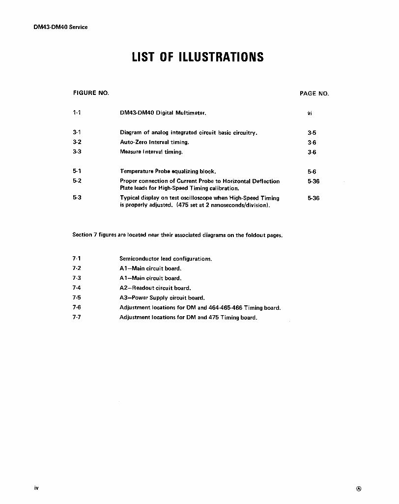
DM43-DM40 Digital Multimeter. νί
3-1
Diagram of analog integrated ci rcuit basic ci rcuitry .
3-53-2
Auto-Zero Interval timing .
3-63-3
Measu re Interval timing.
3-6
5-1
Temperature Probe equalizing block.
5-65-2
Proper connection of Current Probe to H orizontal Deflection
5-36Plate leads for High-Speed Timing calibration .
5-3
Typical display on test oscilloscope when H igh-Speed Timing
5-36is properly adjusted . (475 set at 2 nanosecond s/division) .
Section 7 figures are located nea r their associated diagrams on the foldout pages.
7-1
Semiconductor lead configuratio ns.7-2
All-Main circuit board .
7-3
All-Main circuit board .
7-4
A2-Readout circuit board .
7-5
A3-Power Supply circu it board .
7-6
Adjustment locations for DM and 464-465-466 Timing board .7-7
Adju stment locations for DM and 475 Timing board .
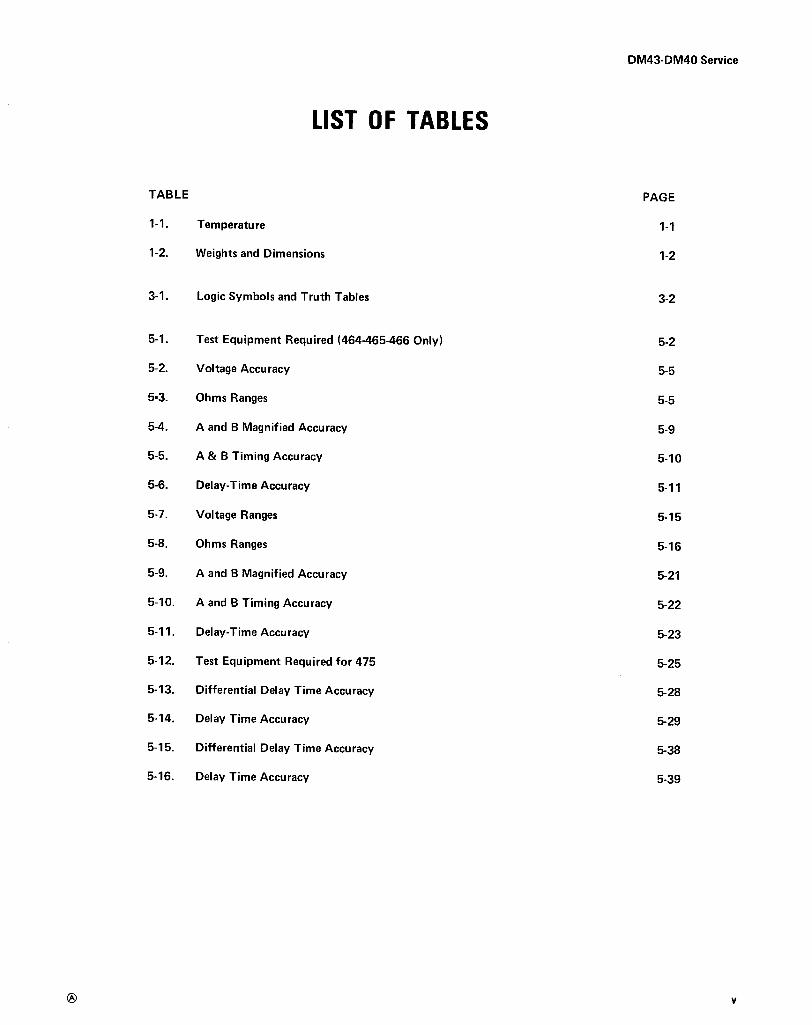
LIST OF TABLES
TABLE
PAGE
1-1 . Temperature
1-1
1-2.
Weights and Dimensions
1-2
3-1 .
Logic Symbols and Truth Tables
3-2
5-1 .
Test Equipment Require d (464-465-466 Only)
5-2
5-2.
Voltage Accuracy
5-5
5-3.
Ohms R anges
5-5
5-4.
Α and Β Magnified Accuracy
5-9
5-5.
Α & Β Timing Accuracy
5-10
5-6.
Delay-Time Accuracy
ς-11
5-7.
Voltage Ranges
5-15
5-8.
Ohms Ranges
5-16
5-9.
Α and Β Magnified Accuracy
5-21
5-10 .
Α and Β Timing Accuracy
ς-22
5-11 .
Delay-Time Accuracy
5-23
5-12 .
Test Equipment Required for 475
5-25
5-13 .
Differential Delay Time Accuracy
ς-28
5-14 .
Delay Time Accuracy
5-29
5-15 .
Differential Delay Time Accuracy
5-38
5-16 .
Delay Time Accuracy
5-39
DM43-DM40 Service
vi
DM43-DM40 Service
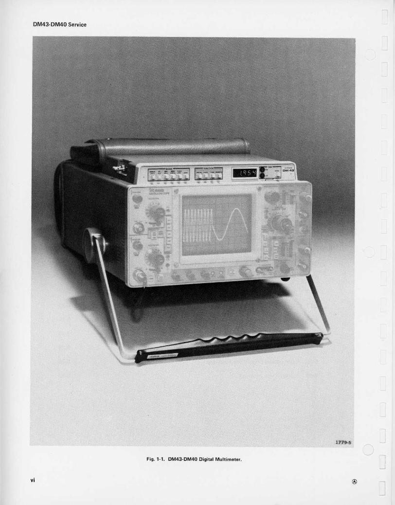
Fig . 1-1 . DM43-DM40 Digital Multimeter .
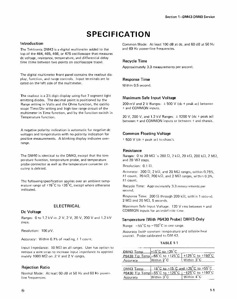
Introd uction
Th e Tektronix D M43 is α digital mult ίmeter added to thetop of t h e 464, 465, 466, or 475 oscilloscope that measuresdo voltage, resistance, temperature, and differential delaytime (time between two points on oscillosco pe trace) .
The digital multimeter front panel contains t h e rea d out dis-play, function, and range controls . In put terminals are lo-cated on the left side of the multimeter .
The DM40 is identical to the D M43, except that t h e tem-perature function, temperature probe, an d temperatureprobe connector as well as the temperature converter cir-cuitry is deleted .
Th e following specification applies over an am bient temp -erature range of +15°ς to +35° C, except wh ere otherwiseindicated .
Dc Voltage
Ranges : 0 to 1 .2 kV in .2 V, 2 V, 20 V, 200 V and 1 .2 kVsteps .
Resolution : 100 μV.
Accuracy : With in 0 .1% of reading, ± 1 count .
S PE CI FICATIONCommon Mode : At least 100 d B at dc, and 80 d B at 50 H zand 60 H z power-line freq uencies .
Recycle Time
App roximately 3.3 measurements per second .
Response TimeWith in 0.5 second .
The readout is α 3'% digit display using five 7-segment lig h t Max i mum Safe Inputd iodes . The decimal point is positione d by the
nput Voltage
Range setting in Volts and the Oh ms function, the oscillo-
200 m V and 2 V R anges : ± 500 V (dc + peak ac) betweenscope Time/Div setting and high-low range circuit of t h e
+ an d CO MM ON inputs .multimeter in Time function, an d by t h e function switch inTem perature function .
20 V, 200 V, an d 1 .2 kV R anges : ± 1200 V ( dc + peak ac)between + an d CO MM ON in puts or between + and ch assis .
Α negative polarity indication is automatic for negative dovoltages and tem peratures with no polarity ind ication for
Common Floating Voltagepositive measurements . Α blink ing display ind icates over-
± 500 V (dc + peak ac) to ch assis .range .
Input Impedance : 10 ΜΩ on all ranges . User has o ption toremove α wire strap to increase input impedance to approxi-
DM 43 Tempmately 1000 ΜΩ on .2 V and 2 V ranges .
Ρ6430 Tip Tem pAccuracy
Rejection Ratio
DM43 Τe_moN ormal Mode : At least 60 d B at 50 H z and 60 H z power-
Ρ6430 Ti p Templine frequencies .
Accuracy
Section 1-DM43-DM40 Service
ResistanceR anges : 0 to 20 ΜΩ in 200 Ω , 2 kΩ , 20 kΩ , 200 kΩ , 2 ΜΩ ,and 20 ΜΩ step s .
R esolution : 0 .1 Ω .
Accuracy : 200 Ω , 2 kΩ , a n d 20 ΜΩ ranges, with in 0.75%,±1 count . 20 kΩ , 200 kΩ , and 2 ΜΩ ranges, within 0.3%,±1 count .
R ecycle Time : Approximately 3 .3 measurements persecond .
R esp onse Time : 200 Ω th rough 200 I<Ω , with in 1 second .2 ΜΩ an d 20 MR 5 second s .
ELE CT RICA L
Maximum Safe In put V oltage : 120 V rms between + andCOMM ON in puts for an i n definite time .
Tem perature (With Ρ6430 Probe) DM43 Only
R ange : -55° C to +150° C in one range .
Accuracy (with constant temperature and infinite heatsource) . Probe calibrated to DM 43 .
TABLE 1-1
+15° C to +35° C-55°C to +125° C
+125°C to +150°CWithin 2 ° C
Within 3° C
-150 C t +15° C and +35°C to +55°C-55° C to +125°C
+125°C to +150° CW ith in 3 ° C
With in 4 ° C
ΟΗΜ5τ
R A N G E 523 Ιρ 2 3
Ι
Ι2L Ιι20.
(F) 20Μη
Ι_
Ι
Ι
ιι
ι
ι
ιΙ
Ι
Ι ~2308
_2 ι Ι
2Ι
~2305Α
R23 ο5α ,R2305[ Ι Κ
ΟΙΙ
Ι
9Μ
Ι
9ΟΟΚ
Ι
90Κ
Ι
Ι
2R1
ιR23ι5
Ι
~23050 Ι Ι1 .2 ΚV
1- _-_ ______
Ι
ι
ΙΟΚ
Ι
~2315 δC23 Ι5(Ε)2 Μη F_____ ι
-
3032L'
~2
1
Ι
Ι
Ι c R 2314
3οΚ
ρΙ0.820Κ 2302 Ι
Ι Ι ι
2
τΙ
~2316 ~23 ι7
ι ~~
~2324200V
ι
ι
2~
1
750κ
Ι
Ι
Ι
Ι
$23ΙΟΕ
30 Κ
ιΜ
Ι2γ C2318
786( ρ) 200ΚηF_____ -
Ι
ί
ι
Ι ~2314
ι .2ΚV
33______ __
_-___FΟΟ 2Μη - -Τ --_ R231$1
to.
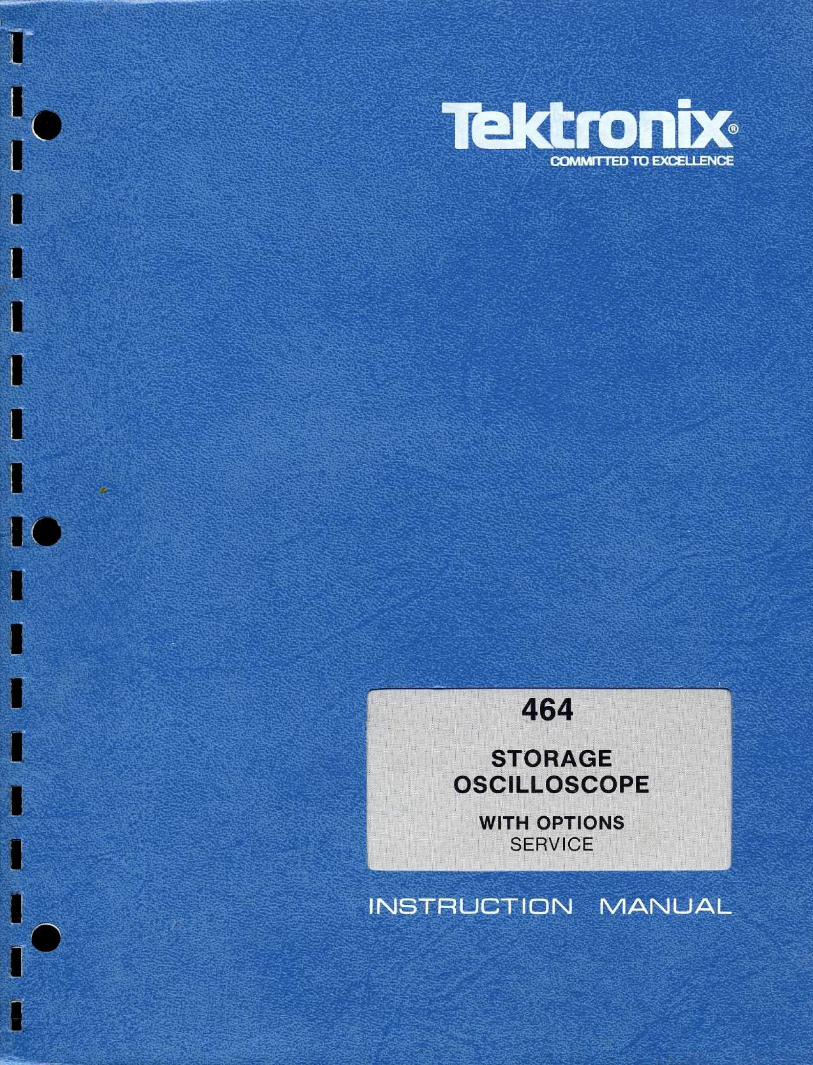
NOTE"
Ι(Β)
2Κπ F ----- -
1 820Κ
+ REMOVE STRAP FOR ΙΟΟΟ MRON 200-V ΑΝ D 2V RANGES Ι
200+~V
1_ Ι_
δ) 20οπ
F _
1 2R -Ι
S2300AVOL TS -------
J2.300(RED)
J2310(Βιηεκ)
SEE PARTS LIST FO RSEMICONDUCTOR TYPES.
523 ι0F
ι
Ι2
Ι (ι) 20Κλ F ----DS2314
20ΜΛF__J2325_______ .
R3Κ
2VQ23264.
2
Ι (ES)
Ί
2
ΟΗΜ5
93?6
ΙιΑί 200πγ3L
R2328β2334_Ρ zι _Ι _-______________________~
~2
3.3κ
5ΟΟ
42322
VR2326
2 31
62
~299"
4?[R2334 ΤΡ 2331
S 263Ν.
- ι 2V- Ι 2 ν
-I2V
νοιΤ~
F _-
το υ 24Ο6
α
+ ι 2V
2336
PM 15Ι[
Ι
Ι 11
CR 2336 ~2337 ~20ΟR 2336
+5 ν
+S V (DCP L 3)
~233 θ
820Κ $
Jag*(OCP L 3)
0234 Ι
R2 34'1
3.3 μ(αι gc
. οο33 zακ U2342B~3 α
α
4'29Ιο 02
~'ι 5
ιΙο
τΡ 23421 ι 2ιΙ
9
+
α 8τ0 υ2442 PIN τ
-
- "--°
U234246ο 2
5
3U2342A ~
642 9(.02
(DCPL1)
7
52300D
3.9Κ
R6139 Κ
R.2354
10ι-F3
-I2Vιzν
GOOK 2 U235ιέΜΡ (° ε) 2 3
_2
C2366τ
Q2352
3
+ Ι2ν
7αιι
.oos
GAINΙ
2
+7 6
~2343
C0.2352
z -4
C23561
Ο 0.2367Ι
Ρ23~9 2 3
3.9 Κ
_1 12γ
0.1
R2366 5003̂~
-I2VR23G5 249 κ R236833 Κ
2 . ΟΚ
3
.οοι
Q2356
2
J 2350
κ
235ΟΟΚ
2
" 3ύΟ "~ρ2
0.Ι
C2355
°
^ υιR2355 ΤΙΜΕΛ(g~33 Ο
C2359.οοι
ΙΙ
ΤΟ2358
Ι
Ι
2
ι ΕΟΟΙ Ο
Ι 2 ι ~FROM Ρ 1 Ι 2Ο-2 ~
F ROM Ρ 11 20-4
1
41
1-~---(
Ρ2379Π
FR OM Ρ1130-8
0
+S V (DIΡL 3~
82361ς 8$342
634OFFSET
ETCz342 } 241
U2344.003 749Ι 2
+I2 V6
3 .9 κ
ν R23 θ 8 C238820, 0. ι
NOTE :
+5ν
I 2V(οιΡι 1)
R2344 IQ2342 ~ 2 "7Κ ; RΖ345
2οκ
R2356
Ι'OK158
5
+5 αν ~1Ε0.2358
ρ
+50`' ι2ν
2 37
Ρ2375F71 Q~330Κ
~4~. . . "
: .°τ0 Ριι2ο- ι
~Ο Ι
12372
τΡ 2372 εΟseκ2ά7α
SΗιειο \ Q237U2378 ί
ΤΟι
+zov
U2372
V_11 z377
Ρ2375
Ρ2379 ν ν.
301Α
43
7
7411
Ι0.
ι
Ι~.
6~~
~FRO. ΡΙΙ30-4
~ "
F ROM ΡΙΙ20-2 -Ιι
Q23746 2 V
+2 ον2
5
1
3 + 7
(
Ι ι Ι
Γ, ΥΓ
FROM Ρ1 120-4 +1
Ι
64
~02κ73
~___1
2_
η
~~~' ΤΟ ΡΙ 130-6
-z .4v Ο
ε2375 Ι
~42376
ά2 Ιk2372
02
R 2376
-2AVη[2377
ΤΡ 2378Τ"
470
ΤΙΜΕ
1
330Κ 00 Ι Ι
Ι Ι Ι
FROM ΡΙΙ30-7 ~FR OM ΡΙΙ 3ο-7
____<
+50V +Η.-
.Ι Ι Ι
R2386
Ι Ι
-2.9 V
ΖΕ RΟ
SHOWN W ITH 475
.Ψι- , C2389
03E0.1
~ _2.9 ν,)V0.23θ9
5. Ιν_8γ
~2 DENOT E COMMO N RETURNΤΟ CEN TER ΤΑΡ L.V TRANSDIAG
Q2DIAG "'+SV (DCPL L) Ι
+12V
Ι
Ι
+Ι
Q2346 ι~~2346
2.2Κ2
523008
Ν 2357
3 + 7
Ρ23~9_
3L1- 1
iΙΟΟΚ
~2369
6 Ι(
68κ
2_ αR2347~
~ CR2357
+,2ν
ν.ro ι -8 νR23752.4κ
!
UZ384
ΤΡ 2384+2 0 ν3
3 σΙΑ+ 7 6
2 θι
4-2,9ν C2383
.Ο 011
ΖΕ Rο
5237 ΙS P RINGRETURN -
R 238GΙΚ
U2312LM 308
+I2V
R2323(-2K
C2361
2~1
~2 ρ02
30004.7�F δ2
6.21 43Ο 2Κα
2ITEMΡ (° ε)
VR 36
2 R 2363
Τ31
U23662 C2369
72 3
Q2354 οοι
R2384
R2385
τ0 ΡιΙ30-51 WΙΚ (5ει)
SE E PARTS LIST
ι ρ237 Ι
PARTIAL At ΜΑιΝ
BOARD
L 1 C_
Ρ 1 Ρ 8
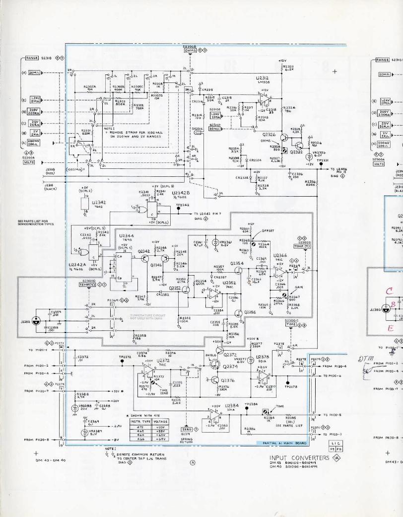
I NPU T CO NVERTE RS ιΑDΜ 43
ΒΟΙΟΙΟΟ-ΒΟΙ09 Ι 9ΟΜ 40 ΒοιοΙοο -ΘΟΙ0499
DIAL
r3i " ΤΟ ΡΙΙ20-3
RAN G E SΖ3 ι0<
2ΟΜπ 1 .-__ .
(ε) L24V2Μπ F ---
200 V(ρ) zοοκ*ι F -- --
J 230 ι
R23916.2 Κ '
Ρ2392 :4.34.
FROM ΡΙΙ30-8 -~
ΟΙ ` Ι ( Ε
DM43- 01
TEKTRONIX®- committed totechnical excellence
MANUAL CHANGE INFORMATIONPRODUCT
Service
Ι DATE
8-22-74
CHANG E : Ι
D ESCR I PTION
DM43/DM40
CHANGE REFERENCE C3/874
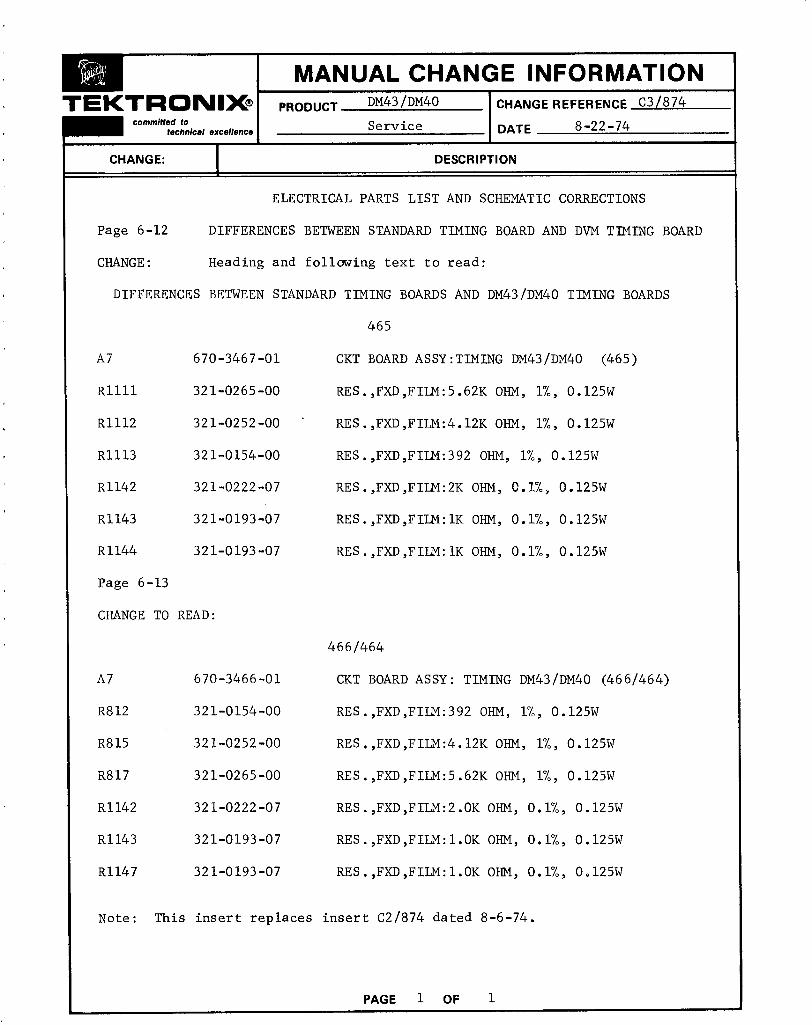
ELECTRICAL PARTS LIST AND SCHEMATIC CORRECTIONS
Page 6-12
DIFFERENCES BETWEEN STANDARD TIMING BOARD AND DVM TIMING BOARD
CHANGE :
Heading and following text to read :
DIFFERENCES BETWEEN STANDARD TIMING BOARDS AND DM43/DM40 TIMING BOARDS
465
Α 7
670-3467-01
CKT BOARD ASSY :TIMING DM43/DM40
(465)
R1111
321-0265-00
RES .,FXD,FILM :5 .62K OHM, 1%, 0 .125W
R1112
321-0252-00
RES .,FXD,FILM :4 .12K OHM, 1%, 0 .125W
R1113
321-0154-00
RES .,FXD,FILM :392 OHM, 1%, 0 .125W
R1142
321-0222-07
RES .,FXD,FILM :2K OHM, 0 .1%, 0 .125W
R1143
321-0193-07
RES .,FXD,FILM :IK OHM, 0 .1%, 0 .125W
R1144
321-0193-07
RES .,FXD,FILM :IK OHM, 0 .1%, 0 .125W
Page 6-13
CHANGE TO READ :
466/464
Α 7
670-3466-01
CKT BOARD ASSY : TIMING DM43/DM40 (466/464)
R812
321-0154-00
RES .,FXD,FILM :392 OHM, 1%, 0 .125W
R815
321-0252-00
RES .,FXD,FILM :4 .12K OHM, 1%, 0 .125W
R817
321-0265-00
RES .,FXD,FILM :5 .62K OHM, 1%, 0 .125W
R1142
321-0222-07
RES .,FXD,FILM :2 .OK OHM, Ο .1%, 0 .125W
R1143
321-0193-07
RES .,FXD,FILM :I .OK OHM, 0 .1%, 0 .125W
R1147
321-0193-07
RES .,FXD,FILM :1 .OK OHM, 0 .1%, 0 .125W
Note : This insert replaces insert C 2/874 dated 8-6-74 .
WARNING
7eIctronbc
THE FOLLOWING SERVICING INSTRUCTIONSARE FOR USE BY QUALI FI ED PERSONNEL ONLY.TO AVOID PERSONAL INJURY, DO NOTPERFORM ANY SERVICING OTHER THAN THATCONTAINED I N OPERATING INSTRUCTIONSUNLESS YOU ARE QUALI FI ED TO DO SO.
Tektronix, Inc .P.O. Box 500Beaverton, Oregon
97077
Serial Number
COMMITTED TO EXCELLENCE
PLEASE CHECK FOR CHANGE INFORMATIONAT THE REAR OF THIS MANUAL.
ooos~, DM44DIGITAL
MULTI METERWITH OPTIONS
SERVICE
INSTRUCTION MANUAL
070-2036-01
First Printing SEP 1976Product Group 40
Revised AUG 1982
Copyright ` 1976, 1979 Tektronix, Inc . All rights reserved .Contents of this publication may not be reproduced in anyform without the written permission of Tektronix, Inc .
Products of Tektronix, Inc . and its subsidiaries are coveredby U .S . and foreign patents and/or pending patents .
TEKTRONIX, TEK, SCOPE-MOBILE, and
R_7~4
areregistered trademarks of Tektronix, Inc . TELEQUIPMENTis a registered trademark of Tektronix U .K . Limited .
Printed in U.S.A . Specification and price change privilegesare reserved .
INSTRUMENT SERIAL NUMBERS
Each instrument has a serial number on a panel insert, tag,or stamped on the chassis . The first number or letterdesignates the country of manufacture . The last five digitsof the serial number are assigned sequentially and areunique to each instrument . Those manufactured in theUnited States have six unique digits . The country ofmanufacture is identified as follows :
13000000
Tektronix, Inc ., Beaverton, Oregon, USA100000
Tektronix Guernsey, Ltd ., Channel Islands200000
Tektronix United Kingdom, Ltd ., London300000
Sony/Tektronix, Japan700000
Tektronix Holland, NV, Heerenveen,The Netherlands
REV A, MAR 1979
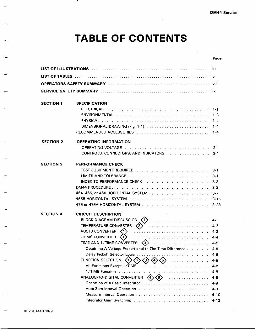
TABLE OF CONTENTS
LIST OF ILLUSTRATIONS
. . . . . . . . . . . . . . . . . . . . . . . . . . . . . . . . . . . . . . . . . . . . . . . . . . . . . . . . . . . . . . .
iii
LIST OF TABLES
. . . . . . . . . . . . . . . . . . . . . . . . . . . . . . . . . . . . . . . . . . . . . . . . . . . . . . . . . . . . . . . . . . . . . . . .
v
OPERATORS SAFETY SUMMARY . . . . . . . . . . . . . . . . . . . . . . . . . . . . . . . . . . . . . . . . . . . . . . . . . . . . . . vii
SERVICE SAFETY SUMMARY . . . . . . . . . . . . . . . . . . . . . . . . . . . . . . . . . . . . . . . . . . . . . . . . . . . . . . . . . . ix
Page
DM44 Service
SECTION 1 SPECIFICATIONELECTRICAL . . . . . . . . . . . . . . . . . . . . . . . . . . . . . . . . . . . . . . . . . . 1-1ENVIRONMENTAL . . . . . . . . . . . . . . . . . . . . . . . . . . . . . . . . . . . . . . 1-3PHYSICAL . . . . . . . . . . . . . . . . . . . . . . . . . . . . . . . . . . . . . . . . . . . 1-4DIMENSIONAL DRAWING (Fig . 1-1) . . . . . . . . . . . . . . . . . . . . . . . . . 1-4
RECOMMENDED ACCESSORIES . . . . . . . . . . . . . . . . . . . . . . . . . . . . . 1-4
SECTION 2 OPERATING INFORMATIONOPERATING VOLTAGE . . . . . . . . . . . . . . . . . . . . . . . . . . . . . . . . . . 2-1CONTROLS, CONNECTORS, AND INDICATORS . . . . . . . . . . . . . . . . . 2-1
SECTION 3 PERFORMANCE CHECKTEST EQUIPMENT REQUIRED . . . . . . . . . . . . . . . . . . . . . . . . . . . . . . 3-1LIMITS AND TOLERANCE . . . . . . . . . . . . . . . . . . . . . . . . . . . . . . . . 3-1INDEX TO PERFORMANCE CHECK . . . . . . . . . . . . . . . . . . . . . . . . . . 3-3
DM44 PROCEDURE . . . . . . . . . . . . . . . . . . . . . . . . . . . . . . . . . . . . . . . 3-3464, 465, or 466 HORIZONTAL SYSTEM . . . . . . . . . . . . . . . . . . . . . . . . 3-7465B HORIZONTAL SYSTEM . . . . . . . . . . . . . . . . . . . . . . . . . . . . . . . . 3-15475 or 475A HORIZONTAL SYSTEM . . . . . . . . . . . . . . . . . . . . . . . . . . . 3-23
SECTION 4 CIRCUIT DESCRIPTIONBLOCK DIAGRAM DISCUSSION 1O . . . . . . . . . . . . . . . . . . . . . . 4-1TEMPERATURE CONVERTER 20 . . . . . . . . . . . . . . . . . . . . . . . . 4-2VOLTS CONVERTER 1 . . . . . . . . . . . . . . . . . . . . . . . . . . . . . . 4-3OHMS CONVERTER . . . . . . . . . . . . . . . . . . . . . . . . . . . . . . 4-4TIME AND 1 /TIME CONVERTER 30 . . . . . . . . . . . . . . . . . . . . . . 4-5
Obtaining A Voltage Proportional to The Time Difference . . . . . . . . . 4-5Delay Pickoff Selector Logic . . . . . . . . . . . . . . . . . . . . . . . . . . . . . 4-6
FUNCTION SELECTION 1002 03 4005 . . . . . . . . . . . . . . . 4-8All Functions Except 1 /TIME . . . . . . . . . . . . . . . . . . . . . . . . . . . . 4-81 /TIME Function . . . . . . . . . . . . . . . . . . . . . . . . . . . . . . . . . . . . 4-8
ANALOG-TO-DIGITAL CONVERTER 40 60 . . . . . . . . . . . . . . . . 4-8Operation of a Basic Integrator . . . . . . . . . . . . . . . . . . . . . . . . . . . 4-9Auto Zero Interval Operation . . . . . . . . . . . . . . . . . . . . . . . . . . . . 4-9Measure Interval Operation . . . . . . . . . . . . . . . . . . . . . . . . . . . . . 4-10Integrator Gain Switching . . . . . . . . . . . . . . . . . . . . . . . . . . . . . . 4-12
DM44 Service
TABLE OF CONTENTS (cont)
CHANGE INFORMATION
11
REV A, MAR 1979
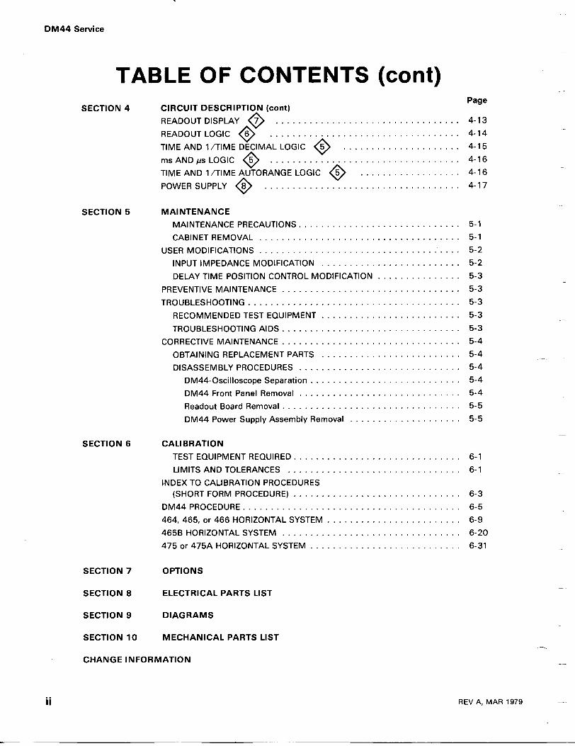
PageSECTION 4 CIRCUIT DESCRIPTION (cont)
READOUT DISPLAY 77 . . . . . . . . . . . . . . . . . . . . . . . . . . . . . . . . . 4-13
READOUT LOGIC O . . . . . . . . . . . . . . . . . . . . . . . . . . . . . . . . . . 4-14
TIME AND 1 /TIME DECIMAL LOGIC O5 . . . . . . . . . . . . . . . . . . . . . 4-15
ms AND us LOGIC O5. . . . . . . . . . . . . . . . . . . . . . . . . . . . . . . . . .
4-16TIME AND 1 /TIME AUTORANGE LOGIC 5O . . . . . . . . . . . . . . . . . . 4-16
POWER SUPPLY O . . . . . . . . . . . . . . . . . . . . . . . . . . . . . . . . . . . 4-17
SECTION 5 MAINTENANCEMAINTENANCE PRECAUTIONS . . . . . . . . . . . . . . . . . . . . . . . . . . . . . 5-1
CABINET REMOVAL . . . . . . . . . . . . . . . . . . . . . . . . . . . . . . . . . . . . 5-1
USER MODIFICATIONS . . . . . . . . . . . . . . . . . . . . . . . . . . . . . . . . . . . . 5-2INPUT IMPEDANCE MODIFICATION . . . . . . . . . . . . . . . . . . . . . . . . . 5-2
DELAY TIME POSITION CONTROL MODIFICATION . . . . . . . . . . . . . . . 5-3
PREVENTIVE MAINTENANCE . . . . . . . . . . . . . . . . . . . . . . . . . . . . . . . . 5-3
TROUBLESHOOTING . . . . . . . . . . . . . . . . . . . . . . . . . . . . . . . . . . . . . . 5-3
RECOMMENDED TEST EQUIPMENT . . . . . . . . . . . . . . . . . . . . . . . . . 5-3
TROUBLESHOOTING AIDS . . . . . . . . . . . . . . . . . . . . . . . . . . . . . . . . 5-3CORRECTIVE MAINTENANCE . . . . . . . . . . . . . . . . . . . . . . . . . . . . . . . . 5-4
OBTAINING REPLACEMENT PARTS . . . . . . . . . . . . . . . . . . . . . . . . . 5-4
DISASSEMBLY PROCEDURES . . . . . . . . . . . . . . . . . . . . . . . . . . . . . 5-4DM44-Oscilloscope Separation . . . . . . . . . . . . . . . . . . . . . . . . . . . 5-4DM44 Front Panel Removal . . . . . . . . . . . . . . . . . . . . . . . . . . . . . 5-4
Readout Board Removal . . . . . . . . . . . . . . . . . . . . . . . . . . . . . . . . 5-5
DM44 Power Supply Assembly Removal . . . . . . . . . . . . . . . . . . . . 5-5
SECTION 6 CALIBRATIONTEST EQUIPMENT REQUIRED . . . . . . . . . . . . . . . . . . . . . . . . . . . . . . 6-1LIMITS AND TOLERANCES . . . . . . . . . . . . . . . . . . . . . . . . . . . . . . . 6-1
INDEX TO CALIBRATION PROCEDURES(SHORT FORM PROCEDURE) . . . . . . . . . . . . . . . . . . . . . . . . . . . . . . 6-3
DM44 PROCEDURE . . . . . . . . . . . . . . . . . . . . . . . . . . . . . . . . . . . . . . . 6-5464, 465, or 466 HORIZONTAL SYSTEM . . . . . . . . . . . . . . . . . . . . . . . . 6-9465B HORIZONTAL SYSTEM . . . . . . . . . . . . . . . . . . . . . . . . . . . . . . . . 6-20475 or 475A HORIZONTAL SYSTEM . . . . . . . . . . . . . . . . . . . . . . . . . . . 6-31
SECTION 7 OPTIONS
SECTION 8 ELECTRICAL PARTS LIST
SECTION 9 DIAGRAMS
SECTION 10 MECHANICAL PARTS LIST

LIST OF ILLUSTRATIONS
DM44 Service
REV AUG 1981
111
FIGURE NO. Page
DM44 Digital Multimeter . . . . . . . . . . . . . . . . . . . . . . . . . . . . . . . . . . . . . . . . . . . x
1-1 DM44 dimensional drawing . . . . . . . . . . . . . . . . . . . . . . . . . . . . . . . . . 1-4
2-1 DM44 controls, connectors, and indicators . . . . . . . . . . . . . . . . . . . . . . . 2-1
3-1 Sealed portion of temperature probe . . . . . . . . . . . . . . . . . . . . . . . . . . . 3-53-2 Temperature probe equalizing block . . . . . . . . . . . . . . . . . . . . . . . . . . . 3-53-3 Timing accuracies . . . . . . . . . . . . . . . . . . . . . . . . . . . . . . . . . . . . . . . . 3-103-4 Mixed sweep timing accuracy . . . . . . . . . . . . . . . . . . . . . . . . . . . . . . . . 3-113-5 Timing accuracies . . . . . . . . . . . . . . . . . . . . . . . . . . . . . . . . . . . . . . . . 3-183-6 Timing accuracies . . . . . . . . . . . . . . . . . . . . . . . . . . . . . . . . . . . . . . . . 3-25
4-1 Simplified block diagram of the DM44 . . . . . . . . . . . . . . . . . . . . . . . . . . 4-14-2 Simplified diagram of the Temperature Converter . . . . . . . . . . . . . . . . . . 4-24-3 Simplified diagram of the VOLTS Converter . . . . . . . . . . . . . . . . . . . . . . 4-3
4-4 Simplified diagram of the OHMS Converter . . . . . . . . . . . . . . . . . . . . . . 4-44-5 Basic function of the TIME and 1 /TIME Converter . . . . . . . . . . . . . . . . . 4-54-6 Obtaining a voltage proportional to the time interval being measured . . . . 4-54-7 Simplified diagram of the Delay Pickoff Selector Logic . . . . . . . . . . . . . . . 4-64-8 Delay Pickoff Selector Logic selects which control determines the
beginning of B sweep . . . . . . . . . . . . . . . . . . . . . . . . . . . . . . . . . . . 4-7
4-9 Timing diagram of Delay Pickoff Selector Logic signals generated in theALT vertical mode . . . . . . . . . . . . . . . . . . . . . . . . . . . . . . . . . . . . . . 4-7
4-10 1 /TIME FUNCTION switching . . . . . . . . . . . . . . . . . . . . . . . . . . . . . . . . 4-84-11 Simplified diagram of a basic integrator . . . . . . . . . . . . . . . . . . . . . . . . . 4-94-12 Auto zero interval timing . . . . . . . . . . . . . . . . . . . . . . . . . . . . . . . . . . . 4-94-13 Simplified diagram of the Analog-to-Digital Converter . . . . . . . . . . . . . . . 4-104-14 Measure interval timing with negative Vi� . . . . . . . . . . . . . . . . . . . . . . . 4-114-15 Simplified diagram of the Integrator Gain Switching circuit . . . . . . . . . . . 4-124-16 Block diagram of the Readout Display and associated circuitry . . . . . . . . . 4-134-17 Simplified diagram of the Readout Logic . . . . . . . . . . . . . . . . . . . . . . . . 4-144-18 Simplified diagram of TIME and 1 /TIME Decimal Logic . . . . . . . . . . . . . . 4-154-19 Simplified diagram of ms and ps Logic when in the 1 /TIME function . . . . 4-164-20 Simplified diagram of ms and has Logic when in the TIME function . . . . . . 4-164-21 Simplified diagram of TIME and 1 /TIME Autorange Logic . . . . . . . . . . . . 4-17
5-1 Cover removal . . . . . . . . . . . . . . . . . . . . . . . . . . . . . . . . . . . . . . . . . . 5-15-2 User modification . . . . . . . . . . . . . . . . . . . . . . . . . . . . . . . . . . . . . . . . 5-25-3 DM44-Oscilloscope separation . . . . . . . . . . . . . . . . . . . . . . . . . . . . . . . 5-5
5-4 DM44 Power Supply assembly removal . . . . . . . . . . . . . . . . . . . . . . . . . 5-6
6-1 Sealed portion of temperature probe . . . . . . . . . . . . . . . . . . . . . . . . . . . 6-76-2 Temperature probe equalizing block . . . . . . . . . . . . . . . . . . . . . . . . . . . 6-86-3 Sweep start and stop adjustment (464, 465, or 466) . . . . . . . . . . . . . . . . 6-106-4 Timing accuracies . . . . . . . . . . . . . . . . . . . . . . . . . . . . . . . . . . . . . . . . 6-176-5 Mixed sweep accuracy . . . . . . . . . . . . . . . . . . . . . . . . . . . . . . . . . . . . . 6-19
DM44 Service
IV
LIST OF ILLUSTRATIONS (cont)
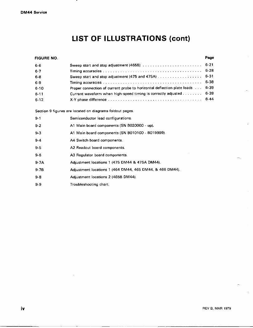
Section 9 figures are located on diagrams foldout pages.
9-1
Semiconductor lead configurations .
9-2
A1 Main board components (SN 13020000 - up).
9-3
A1 Main board components (SN 13010100 - B01 9999).
9-4
A4 Switch board components .
9-5
A2 Readout board components .
9-6
A3 Regulator board components .
9-7A
Adjustment locations 1 (475 DM44 & 475A DM44).
9-713
Adjustment locations 1 (464 DM44, 465 DM44, & 466 DM44).
9-8
Adjustment locations 2 (46513 DM44).
9-9
Troubleshooting chart.
REV B, MAR 1979
FIGURE NO. Page
6-6 Sweep start and stop adjustment (46513) . . . . . . . . . . . . . . . . . . . . . . . . 6-21
6-7 Timing accuracies . . . . . . . . . . . . . . . . . . . . . . . . . . . . . . . . . . . . . . . . 6-28
6-8 Sweep start and stop adjustment (475 and 475A) . . . . . . . . . . . . . . . . . . 6-31
6-9 Timing accuracies . . . . . . . . . . . . . . . . . . . . . . . . . . . . . . . . . . . . . . . . 6-38
6-10 Proper connection of current probe to horizontal deflection plate leads . . . 6-39
6-11 Current waveform when high-speed timing is correctly adjusted . . . . . . . . 6-39
6-12 X-Y phase difference . . . . . . . . . . . . . . . . . . . . . . . . . . . . . . . . . . . . . . 6-44
REV A, MAR 1979
LIST OF TABLES
DM44 Service
V
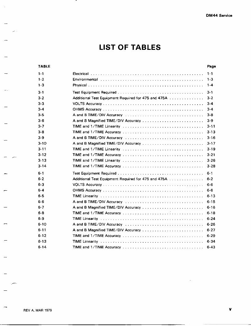
TABLE Page
1-1 Electrical . . . . . . . . . . . . . . . . . . . . . . . . . . . . . . . . . . . . . . . . . . . . . . 1-1
1-2 Environmental . . . . . . . . . . . . . . . . . . . . . . . . . . . . . . . . . . . . . . . . . . 1-31-3 Physical . . . . . . . . . . . . . . . . . . . . . . . . . . . . . . . . . . . . . . . . . . . . . . . 1-4
3-1 Test Equipment Required . . . . . . . . . . . . . . . . . . . . . . . . . . . . . . . . . . . 3-13-2 Additional Test Equipment Required for 475 and 475A . . . . . . . . . . . . . . 3-23-3 VOLTS Accuracy . . . . . . . . . . . . . . . . . . . . . . . . . . . . . . . . . . . . . . . . . 3-43-4 OHMS Accuracy . . . . . . . . . . . . . . . . . . . . . . . . . . . . . . . . . . . . . . . . . 3-43-5 A and B TIME/DIV Accuracy . . . . . . . . . . . . . . . . . . . . . . . . . . . . . . . . 3-83-6 A and B Magnified TIME/DIV Accuracy . . . . . . . . . . . . . . . . . . . . . . . . . 3-93-7 TIME and 1 /TIME Linearity . . . . . . . . . . . . . . . . . . . . . . . . . . . . . . . . . 3-113-8 TIME and 1 /TIME Accuracy . . . . . . . . . . . . . . . . . . . . . . . . . . . . . . . . . 3-133-9 A and B TIME/DIV Accuracy . . . . . . . . . . . . . . . . . . . . . . . . . . . . . . . . 3-163-10 A and B Magnified TIME/DIV Accuracy . . . . . . . . . . . . . . . . . . . . . . . . . 3-173-11 TIME and 1 /TIME Linearity . . . . . . . . . . . . . . . . . . . . . . . . . . . . . . . . . 3-193-12 TIME and 1 /TIME Accuracy . . . . . . . . . . . . . . . . . . . . . . . . . . . . . . . . . 3-213-13 TIME and 1 /TIME Linearity . . . . . . . . . . . . . . . . . . . . . . . . . . . . . . . . . 3-263-14 TIME and 1 /TIME Accuracy . . . . . . . . . . . . . . . . . . . . . . . . . . . . . . . . . 3-28
6-1 Test Equipment Required . . . . . . . . . . . . . . . . . . . . . . . . . . . . . . . . . . . 6-16-2 Additional Test Equipment Required for 475 and 475A . . . . . . . . . . . . . . 6-26-3 VOLTS Accuracy . . . . . . . . . . . . . . . . . . . . . . . . . . . . . . . . . . . . . . . . . 6-66-4 OHMS Accuracy . . . . . . . . . . . . . . . . . . . . . . . . . . . . . . . . . . . . . . . . . 6-66-5 TIME Linearity . . . . . . . . . . . . . . . . . . . . . . . . . . . . . . . . . . . . . . . . . . 6-136-6 A and B TIME/DIV Accuracy . . . . . . . . . . . . . . . . . . . . . . . . . . . . . . . . 6-156-7 A and B Magnified TIME/DIV Accuracy . . . . . . . . . . . . . . . . . . . . . . . . . 6-166-8 TIME and 1 /TIME Accuracy . . . . . . . . . . . . . . . . . . . .
.. . . . . . . . . . . . . 6-18
6-9 TIME Linearity . . . . . . . . . . . . . . . . . . . . . . . . . . . . . . . . . . . . . . . . . . 6-246-10 A and B TIME/DIV Accuracy . . . . . . . . . . . . . . . . . . . . . . . . . . . . . . . . 6-266-11 A and B Magnified TIME/DIV Accuracy . . . . . . . . . . . . . . . . . . . . . . . . . 6-276-12 TIME and 1 /TIME Accuracy . . . . . . . . . . . . . . . . . . . . . . . . . . . . . . . . . 6-296-13 TIME Linearity . . . . . . . . . . . . . . . . . . . . . . . . . . . . . . . . . . . . . . . . . . 6-346-14 TIME and 1 /TIME Accuracy . . . . . . . . . . . . . . . . . . . . . . . . . . . . . . . . . 6-43
@ MAR 1979
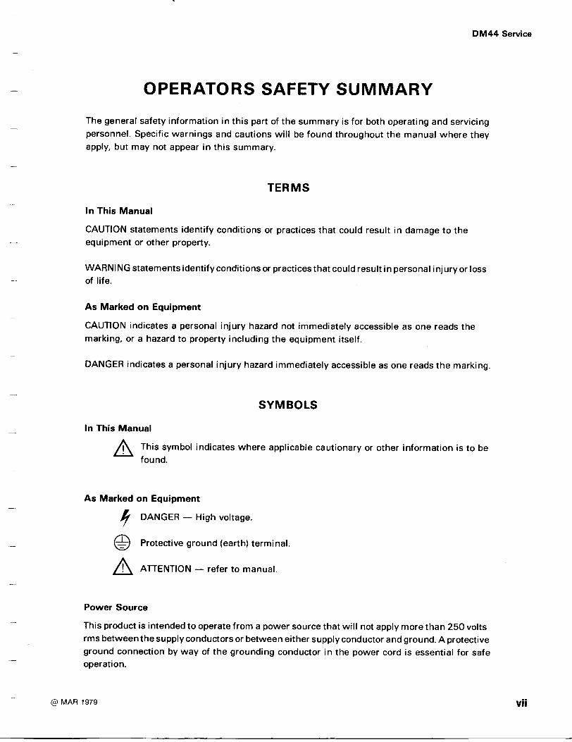
The general safety information in this part of the summary is for both operating and servicingpersonnel . Specific warnings and cautions will be found throughout the manual where theyapply, but may not appear in this summary.
In This Manual
CAUTION statements identify conditions or practices that could result in damage to theequipment or other property.
WARNING statements identify conditions or practices that could result in personal injury or lossof life .
As Marked on Equipment
In This Manual
As Marked on Equipment
Power Source
OPERATORS SAFETY SUMMARY
TERMS
CAUTION indicates a personal injury hazard not immediately accessible as one reads themarking, or a hazard to property including the equipment itself.
DANGER indicates a personal injury hazard immediately accessible as one reads the marking .
SYMBOLS
Q This symbol indicates where applicable cautionary or other information is to befound.
DANGER - High voltage.
Protective ground (earth) terminal .
A ATTENTION - refer to manual .
This product is intended to operate from a power source that will not apply more than 250 voltsrmsbetween the supply conductors or between either supply conductor and ground . Aprotectiveground connection by way of the grounding conductor in the power cord is essential for safeoperation.
DM44 Service
DM44 Service
Viii
Grounding the Product
This product is grounded throughthe grounding conductor of the power cord . To avoid electricalshock, plug the power cord into a properly wired receptacle before connecting to the product
input or output terminals. A protective ground connection by wayof the grounding conductor inthe power cord is essential for safe operation.
Use the Proper Power Cord
Use only the power cord and connector specified for your product.Use only a power cord that is in good condition.
For detailed information on power cords and connectors, refer to the associated oscilloscopemanual .
Refer cord and connector changes to qualified service personnel.
Use the Proper Fuse
To avoid fire hazard, use only the fuse specified in the parts list for your product, and which isidentical in type, voltage rating, and current rating .
Refer fuse replacement to qualified service personnel.
Do Not Operate in Explosive Atmospheres
To avoid explosion, do not operatethis product in an atmosphere of explosive gases unless it hasbeen specifically certified for such operation .
Do Not Remove Covers or Panels
To avoid personal injury, do notremove theproduct covers or panels . Do not operate theproductwithout the covers and panels properly installed.
@ MAR 1979
Do Not Service Alone
SERVICING SAFETY SUMMARYFOR QUALIFIED SERVICE PERSONNEL ONLY
Refer also to the preceding Operators Safety Summary.
Do not perform internal service or adjustment of this product unless another person capable ofrendering first aid and resuscitation is present .
Use Care When Servicing With Power On
Disconnect power before removing protective panels, soldering, or replacing components .
Power Source
DM44 Service
Dangerous voltages exist at several points in this product . To avoid personal injury, do not touchexposed connections and components while power is on .
This product is intended to operate from a power source that will not apply more than 250 voltsrms between the supply conductors or between either supply conductor and ground . A protectiveground connection by way of the grounding conductor in the power cord is essential for safeoperation .

DM44 Service
DM44 Digital Multimeter
2036-49
X
REV AUG 198 1
SPECIFICATION
Section 1-DM44 Service
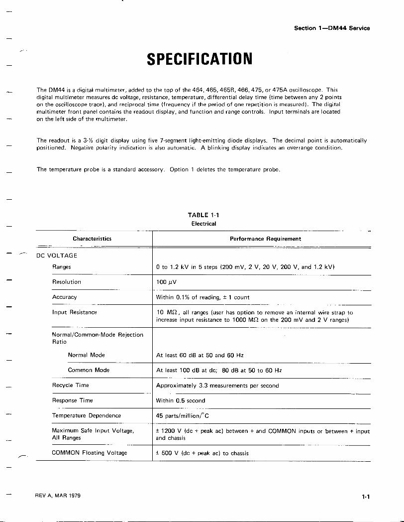
The DM44 is a digital multimeter, added to the top of the 464, 465, 46513, 466, 475, or 475A oscilloscope . Thisdigital multimeter measures do voltage, resistance, temperature, differential delay time (time between any 2 pointson the oscilloscope trace), and reciprocal time (frequency if the period of one repetition is measured) . The digitalmultimeter front panel contains the readout display, and function and range controls . Input terminals are locatedon the left side of the multimeter .
The readout is a 3-'h digit display using five 7-segment light-emitting diode displays . The decimal point is automaticallypositioned . Negative polarity indication is also automatic. A blinking display indicates an overrange condition .
The temperature probe is a standard accessory. Option 1 deletes the temperature probe.
REV A, MAR 1979
TABLE 1-1Electrical
Characteristics Performance Requirement
DC VOLTAGE
Ranges 0 to 1 .2 kV in 5 steps (200 mV, 2 V, 20 V, 200 V, and 1 .2 kV)
Resolution 100 JUV
Accuracy Within 0.1% of reading, ± 1 count
Input Resistance 10 ME2, all ranges (user has option to remove an internal wire strap toincrease input resistance to 1000 ME2 on the 200 mV and 2 V ranges)
Normal/Common-Mode RejectionRatio
Normal Mode At least 60 dB at 50 and 60 Hz
Common Mode At least 100 dB at dc ; 80 dB at 50 to 60 Hz
Recycle Time Approximately 3.3 measurements per second
Response Time Within 0.5 second
Temperature Dependence 45 parts/millionrC
Maximum Safe Input Voltage,All Ranges
± 1200 V (dc + peak ac) between + and COMMON inputs or between + inputand chassis
COMMON Floating Voltage ± 500 V (dc + peak ac) to chassis
Specification-DM44 Service
TABLE 1-1 (cont.)Electrical
REV B FEB 1980
Characteristics Performance Requirement
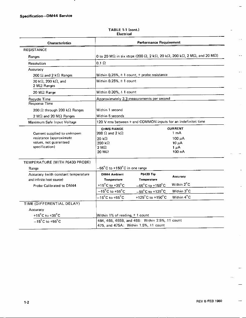
RESISTANCE
Ranges 0 to 20 MQ in six steps (200 Q, 2 kQ, 20 kQ, 200 kQ, 2 MQ, and 20 MS2)
Resolution 0.1 S2
Accuracy
200 Q and 2 kQ Ranges Within 0.25%, ± 1 count, + probe resistance
20 kE2, 200 k2, and Within 0.25%, ± 1 count2 MS2 Ranges
20 MS2 Range Within 0 .30°/x, ± 1 count
Recycle Time A. iroximatel 3.3 measurements per secondResponse Time
200 S2 through 200 k&2 Ranges Within 1 second
2 MS2 and 20 MS2 Ranges Within 5 seconds
Maximum Safe Input Voltage 120 V rms between + and COMMON inputs for an indefinitet time
OHMSRANGE CURRENTCurrent supplied to unknown 200 SZ and 2 kE2 1 mAresistance (approximate 20 kQ 100,Avalues, not guaranteed 200 kQ 10 MAspecification) 2 MS2 1 juA
20 MS2 100 nA
TEMPERATURE (WITH P6430 PROBE)
Range -55° C to +150° C in one range
Accuracy (with constant temperature DM44 Ambient P6430 TipAccuracy
and infinite heat source) Temperature Temperature
Probe Calibrated to DM44 +15° C to +35° C -55° C to +150° C Within 2° C
-15°C to +55°C -55° C to +125° C Within 3° C
-15° C to +55° C +125°C to +150° C Within 4° C
TIME (DIFFERENTIAL DELAY)
Accuracy
+15°C to +35°C Within 1% of reading, +- 1 count
-15° C to +55° C 464, 465, 465B, and 466: Within 2 .5%, ±1 count475, and 475A : Within 1 .5%, ±1 count
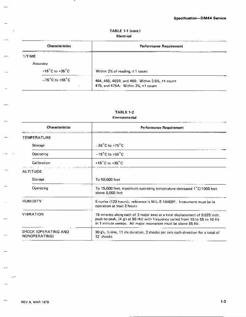
1 /TIME
Accuracy
+15° C to +35 0 C
REV A, MAR 1979
Characteristics
-15 °C to +550 C
TABLE 1-1 (cont.)Electrical
Within 2% of reading, ± 1 count
TABLE 1-2Environmental
Performance Requirement
464, 465, 465B, and 466 : Within 3.5%, ±1 count475, and 475A : Within 3%, ±1 count
Specification-DM44 Service
Characteristics Performance Requirement
TEMPERATURE
Storage -55° C to +75° C
Operating -15° C to +55 ° C
Calibration +15°C to +35° C
ALTITUDE
Storage To 50,000 feet
Operating To 15,000 feet, maximum operating temperature decreased 1 ° C/1000 feetabove 5,000 feet
HUMIDITY 5 cycles (120 hours) ; reference is MIL-E-16400F . Instrument must be inoperation at least 2 hours
VIBRATION 15 minutes along each of 3 major axes at a total displacement of 0.025 inch,peak-to-peak, (4 g's at 55 Hz) with frequency varied from 10 to 55 to 10 Hzin 1 minute sweeps . All major resonances must be above 55 Hz .
SHOCK (OPERATING AND 30 g's, 1/2 sine, 11 ms duration, 2 shocks per axis each direction for a total ofNONOPERATING) 12 shocks

Specification-DM44 Service
1 PAIR TEST LEADS
TABLE 1-3Physical
Fig. 1-1 . DM44 dimensional drawing.
STANDARD ACCESSORIES
(Refer to Mechanical Parts List)
RECOMMENDED ACCESSORIES
One test lead with probe on one end and banana plug on the other. One test lead with grounding clip on one end andbanana plug on the other.
order Tektronix Part . . . . . . . 012-0427-00
1-4
REV B, MAR 1979
Characteristics Performance Requirement
DM44 AND MAINFRAME WEIGHT
With Panel Cover, Accessories, and Pouch
465-475 DM44
29.5 Ibs (13.4 kg)
464-466 DM44
31 .0 Ibs (14.0 kg)
Without Panel Cover, Accessories, and Pouch 26.5 Ibs (12.0 kg) 28.0 Ibs (12.7 kg)
DOMESTIC SHIPPING WEIGHT 36.0 Ibs (16.7 kg) 38.9 Ibs (17.6 kg)
DIMENSIONS See Figure 1-1

OPERATING INFORMATION
The following information will familiarize you with the location and basic operation of the DM44 . If you need detailedoperating instructions, see the Operator's manual .
OPERATING VOLTAGEThe DM44 gets its operating voltage from the instrumentto which it is attached . See the oscilloscope Servicemanual or the Operator's manual for operating voltageinformation .
CONTROLS, CONNECTORS, AND INDICATORSFigure 2-1 shows the location of the DM44 controls,connectors, and indicators . The numbers in Figure 2-1correspond to the number preceding the discussion ofthat control .
lO Input Connectors-Two banana jacks, + (red) andCOM (black), provide inputs for voltage andresistance only .
REV A, MAR 1979
Fig. 2-1 . DM44 controls, connectors, and indicators.
Section 2-DM44 Service
Probe Connector-Input connector for the tempera-ture probe .
O Readout-A 3-'/z digit display. Negative measurementindication is automatic for negative do voltage andtemperature . No polarity indication is shown forpositive measurements . Decimal point location isautomatic for all functions.
RANGE-Selects from .2 V to 1 .2 kV in five rangesand from 200 2 to 20 MS2 in 6 ranges . Maximumsafe input voltage in the VOLTSfunction is 1 .2 kV.
FUNCTION-Selects VOLTS, OHMS, TEMP ( ° C),1/TIME, or TIME functions of the DM44 .
PARTIAL LEFTSIDE PANEL
000000 00000
2036-20
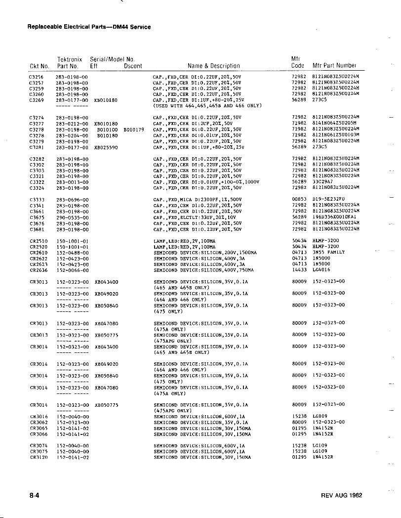
Replaceable Electrical Parts-DM44 Service
8-4
REV AUG 1982
Ckt No .TektronixPart No .
Serial/ModelEff
No .Dscont Name & Description
MfrCode Mfr Part Number
C3256 283-0198-00 CAP .,FXD,CER DI :0 .22UF,20%,50V 72982 8121N083Z5UO224MC3257 283-0198-00 CAP.,FXD,CER DI :0 .22UF,20%,50V 72982 8121N083Z5UO224MC3259 283-0198-00 CAP.,FXD,CER DI :0 .22UF,20%,50V 72982 8121N083Z5UO224MC3260 283-0198-00 CAP.,FXD,CER DI :0 .22UF,20%,50V 72982 8121NO83Z5UO224MC3269 283-0177-00 XBO10180 CAP .,FXD,CER DI :lUF,+80-20%,25V 56289 27305
----- ----- (USED WITH 464,465,465B AND 466 ONLY)
C3274 283-0198-00 CAP .,FXD,CER DI :0 .22UF,20%,50V 72982 8121N083Z5UO224MC3277 283-0212-00 XBO10180 CAP .,FXD,CER DI :2UF,20%,50V 72982 8141NO64Z5U205MC3278 283-0198-00 B010100 B010179 CAP .,FXD,CER DI :0 .22UF,20%,50V 72982 8121N083Z5UO224MC3278 283-0204-00 B010180 CAP .,FXD,CER DI :O .OIUF,20%,50V 72982 8121N06IZ5UO103MC3279 283-0198-00 CAP .,FXD,CER DI :0 .22UF,20%,50V 72982 8121N083Z5UO224MC3281 283-0177-00 XB025590 CAP .,FXD,CER DI :IUF,+80-20%,25V 56289 27305
C3282 283-0198-00 CAP .,FXD,CER DI :0 .22UF,20%,50V 72982 8121N083Z5U0224MC3302 283-0198-00 CAP .,FXD,CER DI :0 .22UF,20%,50V 72982 8121N083Z5U0224MC3303 283-0198-00 CAP .,FXD,CER DI :0 .22UF,20%,50V 72982 8121NO83Z5UO224MC3321 283-0198-00 CAP .,FXD,CER DI :0 .22UF,20%,50V 72982 8121NO83Z5UO224MC3322 283-0013-00 CAP .,FXD,CER DI :O .OIUF,+100-0%,1000V 56289 33C29A7C3324 283-0198-00 CAP .,FXD,CER DI :0 .22UF,20%,50V 72982 8121N083Z5UO224M
C3333 283-0696-00 CAP .,FXD,MICA D :2300PF,1%,500V 00853 D19-5E232FOC3341 283-0198-00 CAP .,FXD,CER DI :0 .22UF,20%,50V 72982 8121NO83Z5UO224MC3661 283-0198-00 CAP .,FXD,CER DI :0 .22UF,20%,50V 72982 8121N083Z5U0224MC3675 290-0535-00 CAP .,FXD,ELCTLT :33UF,20%,IOV 56289 196D336XO010KA1C3676 283-0198-00 CAP .,FXD,CER DI :0 .22UF,20%,50V 72982 8121N083Z5UO224MC3681 283-0198-00 CAP .,FXD,CER DI :0 .22UF,20%,50V 72982 8121N083Z5UO224M
CR2510 150-1001-01 LAMP,LED :RED,2V,l00MA 50434 HLMP-3200CR2520 150-1001-01 LAMP,LED :RED,2V,100MA 50434 HLMP-3200CR2610 152-0488-00 SEMICOND DEVICE:SILICON,200V,1500MA 04713 3N55 FAMILYCR2622 152-0423-00 SEMICOND DEVICE :SILICON,400V,3A 04713 1N5000CR2623 152-0423-00 SEMICOND DEVICE :SILICON,400V,3A 04713 1N5000CR2636 152-0066-00 SEMICOND DEVICE:SILICON,400V,750MA 14433 LG4016
CR3013 152-0323-00 XB043400 SEMICOND DEVICE :SILICON,35V,O .IA 80009 152-0323-00----- ----- (465 AND 465B ONLY)
CR3013 152-0323-00 XB049020 SEMICOND DEVICE :SILICON,35V,O .IA 80009 152-0323-00----- ----- (464 AND 466 ONLY)
CR3013 152-0323-00 XB050840 SEMICOND DEVICE :SILICON,35V,O .IA 80009 152-0323-00----- ----- (475 ONLY)
CR3013 152-0323-00 XB047080 SEMICOND DEVICE :SILICON,35V,O .lA 80009 152-0323-00----- ----- (475A ONLY)
CR3013 152-0323-00 XB050775 SEMICOND DEVICE :SILICON,35V,O .lA 80009 152-0323-00----- ----- (475APG ONLY)
CR3014 152-0323-00 XB043400 SEMICOND DEVICE :SILICON,35v,0 .1A 80009 152-0323-00----- ----- (465 AND 465B ONLY)
CR3014 152-0323-00 XB049020 SEMICOND DEVICE :SILICON,35V,O .lA 80009 152-0323-00----- ----- (464 AND 466 ONLY)
CR3014 152-0323-00 XB050840 SEMICOND DEVICE :SILICON,35V,O .lA 80009 152-0323-00----- ----- (475 ONLY)
CR3014 152-0323-00 XB047080 SEMICOND DEVICE :SILICON,35V,O .IA 80009 152-0323-00----- ----- (475A ONLY)
CR3014 152-0323-00 XBO50775 SEMICOND DEVICE :SILICON,35V,O .lA 80009 152-0323-00----- ----- (475APG ONLY)
CR3016 152-0040-00 SEMICOND DEVICE :SILICON,60OV,IA 15238 LG109CR3062 152-0323-00 SEMICOND DEVICE :SILICON,35V,O .lA 80009 152-0323-00CR3065 152-0141-02 SEMICOND DEVICE :SILICON,30V,150MA 01295 1N4152RCR3066 152-0141-02 SEMICOND DEVICE :SILICON,30V,150MA 01295 IN4152R
CR3074 152-0040-00 SEMICOND DEVICE:SILICON,600V,1A 15238 LG109CR3075 152-0040-00 SEMICOND DEVICE :SILICON,600V,1A 15238 LG109CR3120 152-0141-02 SEMICOND DEVICE :SILICON,30V,150MA 01295 IN4152R
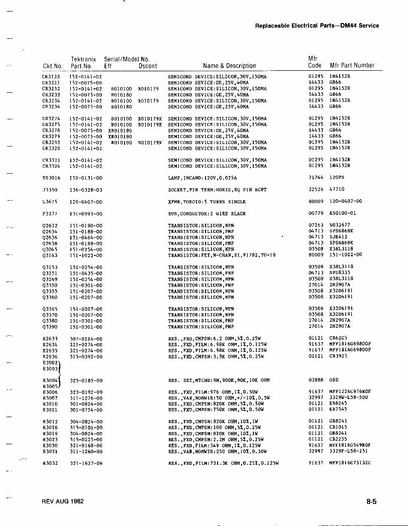
Replaceable Electrical Parts-DM44 Service
REV AUG 1982
8-5
Ckt No .TektronixPart No .
Serial/ModelEff
No .Dscont Name & Description
MfrCode Mfr Part Number
CR3133 152-0141-02 SEMICOND DEVICE:SILICON,30V,150MA 01295 1N4152RCR3221 152-0075-00 SEMICOND DEVICE :GE,25V,40MA 14433 G866CR3232 152-0141-02 B010100 B010179 SEMICOND DEVICE :SILICON,30V,150MA 01295 1N4152RCR3232 152-0075-00 B010180 SEMICOND DEVICE :GE,25V,4014A 14433 G866CR3234 152-0141-02 B010100 B010179 SEMICOND DEVICE :SILICON,30V,150MA 01295 1N4152RCR3234 152-0075-00 B010180 SEMICOND DEVICE :GE,25V,40MA 14433 G866
CR3274 152-0141-02 B010100 B010179X SEMICOND DEVICE :SILICON,30V,150MA 01295 1N4152RCR3275 152-0141-02 B010100 B010179X SEMICOND DEVICE :SILICON,30V,150MA 01295 1N4152RCR3278 152-0075-00 XBO10180 SEMICOND DEVICE :GE,25V,40MA 14433 G866CR3279 152-0075-00 XBO10180 SEMICOND DEVICE :GE,25V,40MA 14433 G866CR3292 152-0141-02 B010100 B010179X SEMICOND DEVICE :SILICON,30V,150MA 01295 1N4152RCR3320 152-0141-02 SEMICOND DEVICE :SILICON,30V,150MA 01295 1N4152R
CR3321 152-0141-02 SEMICOND DEVICE :SILICON,30V,150MA 01295 IN4152RCR3324 152-0141-02 SEMICOND DEVICE :SILICON,30V,150MA 01295 1N4152R
DS3016 150-0131-00 LAMP,INCAND :120V,0 .025A 71744 120PS
J3350 136-0328-03 SOCKET,PIN TERM :HORIZ,SQ PIN RCPT 22526 47710
1,3675 120-0407-00 XFMR,TOROID :5 TURNS SINGLE 80009 120-0407-00
P3277 131-0993-00 BUS,CONDUCTOR :2 WIRE BLACK 00779 850100-01
Q2632 151-0190-00 TRANSISTOR :SILICON,NPN 07263 5032677Q2634 151-0188-00 TRANSISTOR :SILICON,PNP 04713 SPS6868KQ2636 151-0464-00 TRANSISTOR :SILICON,NPN 04713 SJE412Q2638 151-0188-00 TRANSISTOR :SILICON,PNP 04713 SPS6868KQ3045 151-0254-00 TRANSISTOR :SILICON,NPN 03508 X381,3118Q3143 151-1022-00 TRANSISTOR :FET,N-CHAN,SI,F1782,TO-18 80009 151-1022-00
Q3153 151-0254-00 TRANSISTOR :SILICON,NPN 03508 X381,3118Q3251 151-0435-00 TRANSISTOR :SILICON,PNP 04713 SPS8335Q3269 151-0254-00 TRANSISTOR :SILICON,NPN 03508 X381,3118Q3350 151-0301-00 TRANSISTOR :SILICON,PNP 27014 2N2907AQ3355 151-0207-00 TRANSISTOR :SILICON,NPN 03508 X32D6191Q3360 151-0207-00 TRANSISTOR :SILICON,NPN 03508 X32D6191
Q3365 151-0207-00 TRANSISTOR :SILICON,NPN 03508 X32D6191Q3370 151-0207-00 TRANSISTOR :SILICON,NPN 03508 X32D6191Q3380 151-0301-00 TRANSISTOR :SILICON,PNP 27014 2N2907AQ3390 151-0301-00 TRANSISTOR :SILICON,PNP 27014 2N2907A
82633 307-0114-00 RES .,FXD,CMPSN:6.2 OHM,5%,0.25W 01121 CB62G5R2634 321-0274-00 RES .,FXD,FILM :6 .98K OHM,1%,0 .125W 91637 MFF1816G69800F82635 321-0274-00 RES .,FXD,FILM :6 .98K OHM,1%,0 .125W 91637 MFF1816G69800F82636 315-0392-00 RES .,FXD,CMPSN :3.9K OHM,5%,0 .25W 01121 CB3925R3002)
83004I 325-0185-00 RES . SET,MTCHD :9M,900K,90K,1OK OHM 03888 OBD83005183006 323-0192-09 RES .,FXD,FILM :976 OHM,1%,0 .5OW 91637 MFF1226C976ROF83007 311-1276-00 RES .,VAR,NONWIR :50 OHM,+/-10%,0.5W 32997 3329W-L58-500R3010 301-0824-00 RES .,FXD,CMPSN:820K OHM,5%,0 .50W 01121 EB8245R3011 301-0754-00 RES .,FXD,CMPSN :750K OHM,5%,0 .50W 01121 EB7545
83012 304-0824-00 RES .,FXD,CMPSN :820K OHM,10%,1W 01121 GB824183016 315-0101-00 RES .,FXD,CMPSN :100 OHM,5%,0.25W 01121 CB1015R3019 304-0824-00 RES .,FXD,CMPSN:820K OHM,102,1W 01121 GB824183023 315-0225-00 RES .,FXD,CMPSN:2 .2M OHM,52,0 .25W 01121 CB225583030 321-0168-00 RES .,FXD,FILM :549 OHM,1X,0 .125W 91637 MFF1816G549ROF83031 311-1260-00 RES .,VAR,NONWIR :250 OHM,10%,0.50W 32997 3329P-L58-251
83032 321-1627-06 RES .,FXD,FILM :731 .3K OHM,0 .25%,0 .125W 91637 MFF1816C73132C
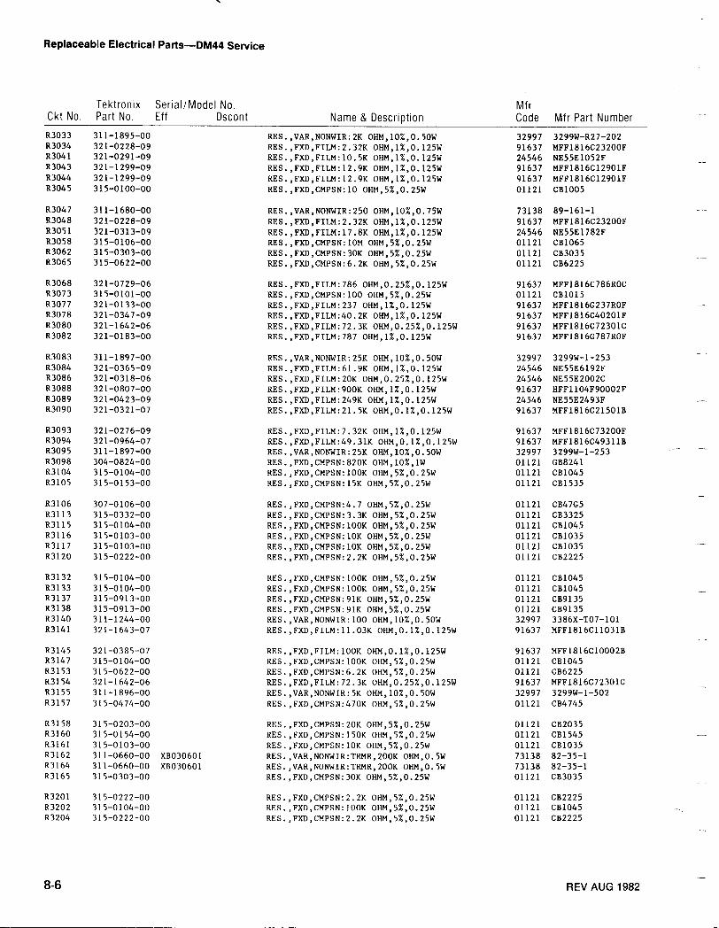
Replaceable Electrical Parts-DM44 Service
8-6
REV AUG 1982
Ckt No .TektronixPart No .
Serial/Model No .Eff Dscont Name & Description
MfrCode Mfr Part Number
83033 311-1895-00 RES.,VAR,NONWIR :2K OHM,10%,0 .50W 32997 3299W-R27-20283034 321-0228-09 RES .,FXD,FILM :2 .32K OHM,1%,0 .125W 91637 MFF1816C23200F83041 321-0291-09 RES .,FXD,FILM :10 .5K OHM,1%,0 .125W 24546 NE55E1052F83043 321-1299-09 RES .,FXD,FILM :12 .9K OHM,1%,0 .125W 91637 MFF1816C12901F83044 321-1299-09 RES .,FXD,FILM :12 .9K OHM,1%,0 .125W 91637 MFF1816C12901F83045 315-0100-00 RES .,FXD,CMPSN:10 OHM,5%,0 .25W 01121 CB1005
R3047 311-1680-00 RES .,VAR,NONWIR :250 OHM,10%,0 .75W 73138 89-161-1R3048 321-0228-09 RES .,FXD,FILM :2 .32K OHM,1%,0 .125W 91637 MFF1816C23200F83051 321-0313-09 RES .,FXD,FILM :17 .8K OHM,1%,0 .125W 24546 NE55E1782FR3058 315-0106-00 RES .,FXD,CMPSN:10M OHM,5%,0 .25W 01121 CB106583062 315-0303-00 RES .,FXD,CMPSN:30K OHM,5%,0.25W 01121 CB3035R3065 315-0622-00 RES .,FXD,CMPSN :6 .2K OHM,5%,0 .25W 01121 CB6225
83068 321-0729-06 RES .,FXD,FILM :786 OHM,0.25%,0 .125W 91637 MFF1816C786ROCR3073 315-0101-00 RES .,FXD,CMPSN :100 OHM,5%,0.25W 01121 CB101583077 321-0133-00 RES .,FXD,FILM :237 OHM,1%,0 .125W 91637 MFF1816G237ROFR3078 321-0347-09 RES.,FXD,FILM :40 .2K OHM,1%,0 .125W 91637 MFF1816C40201F83080 321-1642-06 RES .,FXD,FILM :72 .3K OHM,0.25%,0.125W 91637 MFF1816C72301CR3082 321-0183-00 RES .,FXD,FILM :787 OHM,1%,0 .125W 91637 MFF1816G787ROF
R3083 311-1897-00 RES .,VAR,NONWIR:25K OHM,10%,0 .50W 32997 3299W-1-25383084 321-0365-09 RES .,FXD,FILM :61 .9K OHM,1%,0 .125W 24546 NE55E6192F83086 321-0318-06 RES .,FXD,FILM :20K OHM,0.25%,0 .125W 24546 NE55E2002C83088 321-0807-00 RES .,FXD,FILM :900K OHM,1%,0 .125W 91637 HFF1104F90002FR3089 321-0423-09 RES .,FXD,FILM :249K OHM,1%,0.125W 24546 NE55E2493F83090 321-0321-07 RES .,FXD,FILM :21 .5K OHM,0 .1%,0 .125W 91637 MFF1816C21501B
83093 321-0276-09 RES .,FXD,FILM :7 .32K OHM,1%,0 .125W 91637 MFF1816C73200F83094 321-0964-07 RES .,FXD,FILM :49 .31K OHM,0 .1%,0 .125W 91637 MFF1816C49311B83095 311-1897-00 RES .,VAR,NONWIR:25K OHM,10%,0 .50W 32997 3299W-1-253R3098 304-0824-00 RES .,FXD,CMPSN :820K OHM,10%,lW 01121 GB8241R3104 315-0104-00 RES .,FXD,CMPSN :IOOK OHM,5%,0 .25W 01121 CB104583105 315-0153-00 RES .,FXD,CMPSN :15K OHM,5%,0 .25W 01121 CB1535
83106 307-0106-00 RES .,FXD,CMPSN :4 .7 OHM,5%,0 .25W 01121 CB47G583113 315-0332-00 RES .,FXD,CMPSN :3 .3K OHM,5%,0 .25W 01121 CB332583115 315-0104-00 RES .,FXD,CMPSN :l00K OHM,5%,0 .25W 01121 CB104583116 315-0103-00 RES .,FXD,CMPSN :IOK OHM,5%,0 .25W 01121 CB103583117 315-0103-00 RES .,FXD,CMPSN :10K OHM,5%,0 .25W 01121 CB103583120 315-0222-00 RES .,FXD,CMPSN :2 .2K OHM,5%,0.25W 01121 CB2225
83132 315-0104-00 RES .,FXD,CMPSN :l00K OHM,5%,0 .25W 01121 CB104583133 315-0104-00 RES .,FXD,CMPSN:l00K OHM,5%,0 .25W 01121 CB104583137 315-0913-00 RES .,FXD,CMPSN:91K OHM,5%,0 .25W 01121 CB913583138 315-0913-00 RES .,FXD,CMPSN:91K OHM,5%,0 .25W 01121 CB913583140 311-1244-00 RES .,VAR,NONWIR :100 OHM,10%,0 .50W 32997 3386X-TO7-10183141 321-1643-07 RES .,FXD,FILM :11 .03K OHM,0 .1%,0.125W 91637 MFF1816C11031B
83145 321-0385-07 RES .,FXD,FILM :l00K OHM,0 .1%,0 .125W 91637 MFF1816CI0002B83147 315-0104-00 RES .,FXD,CMPSN :100K OHM,5%,0 .25W 01121 CB104583153 315-0622-00 RES .,FXD,CMPSN :6 .2K OHM,5%,0 .25W 01121 CB622583154 321-1642-06 RES .,FXD,FILM :72 .3K OHM,0 .25%,0.125W 91637 MFF1816C72301C83155 311-1896-00 RES .,VAR,NONWIR :5K OHM,10%,0 .50W 32997 3299W-1-50283157 315-0474-00 RES .,FXD,CMPSN :470K OHM,5%,0 .25W 01121 CB4745
83158 315-0203-00 RES .,FXD,CMPSN :20K OHM,5%,0.25W 01121 CB203583160 315-0154-00 RES .,FXD,CMPSN :150K OHM,5%,0 .25W 01121 CB154583161 315-0103-00 RES .,FXD,CMPSN :10K OHM,5%,0.25W 01121 CB103583162 311-0660-00 XB030601 RES.,VAR,NONWIR:TRMR,200K OHM,0 .5W 73138 82-35-183164 311-0660-00 X8030601 RES .,VAR,NONWIR:TRMR,200K OHM,0 .5W 73138 82-35-183165 315-0303-00 RES .,FXD,CMPSN :30K OHM,5%,0 .25W 01121 CB3035
83201 315-0222-00 RES .,FXD,CMPSN :2 .2K OHM,5%,0 .25W 01121 CB222583202 315-0104-00 RES .,FXD,CMPSN :l00K OHM,5%,0 .25W 01121 CB104583204 315-0222-00 RES .,FXD,CMPSN :2 .2K OHM,5%,0 .25W 01121 CB2225
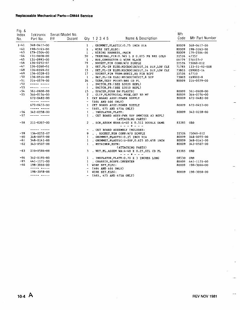
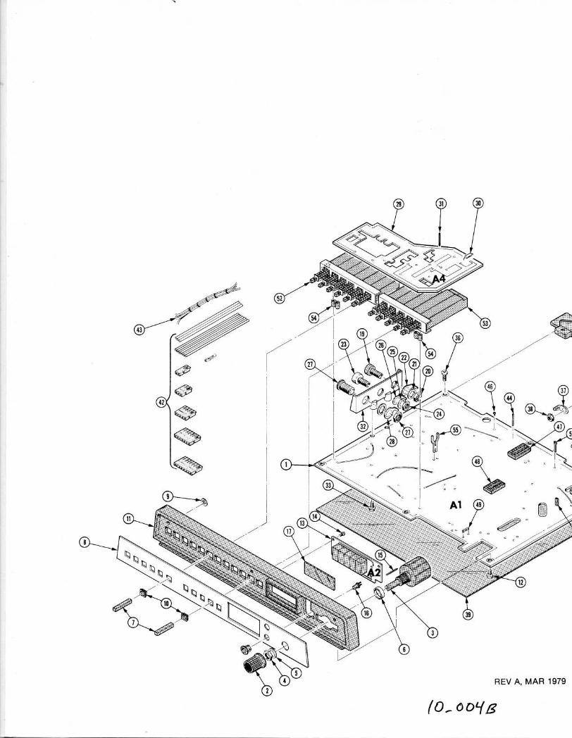
Replaceable Mechanical Parts-DM44 Service
10.4 A
REV NOV 1981
Fig . &IndexNo .
Tektronix Serial/Model No .Part No . Eff Dscont Qty 1 2 3 4 5 Name & Description
MfrCode Mfr Part Number
1-41 348-0417-00 1 . GROMMET,PLASTIC :0 .75 INCH DIA 80009 348-0417-00-42 198-3163-00 1 . WIRE SET,ELEC : 80009 198-3163-00-43 179-2504-00 1 . WIRING HARNESS, :MAIN 80009 179-2504-00-44 131-0608-00 50 . TERMINAL,PIN :0 .365 L X 0 .025 PH BRZ GOLD 22526 47357-45 131-0993-00 1 . BUS,CONDUCTOR :2 WIRE BLACK 00779 530153-2-46 136-0252-07 79 . SOCKET,PIN CONN :W/O DIMPLE 22526 75060-012-47 136-0260-02 2 . SKT,PL-IN ELEK:MICROCIRCUIT,16 DIP,LOW CLE 71785 133-51-92-008-48 136-0269-02 15 . SKT,PL-IN ELEK:MICROCIRCUIT,14 DIP,LOW CLE 73803 CS9002-14-49 136-0328-03 17 . SOCKET,PIN TERM :HORIZ,SQ PIN RCPT 22526 47710-50 136-0514-00 1 . SKT,PL-IN ELEC :MICROCIRCUIT,8 DIP 73803 CS9002-8-51 214-0579-00 24 . TERM,TEST POINT :BRS CD PL 80009 214-0579-00-52 ----- ----- 1 . SWITCH,PB :(SEE 53020 REPL)-53 ----- ----- 1 . SWITCH,PB :(SEE 53010 REPL)-54 361-0608-00 15 . SPACER,PUSH SW :PLASTIC 80009 361-0608-00-55 344-0154-00 2 . CLIP,ELECTRICAL :FUSE,CKT BD MT 80009 344-0154-00
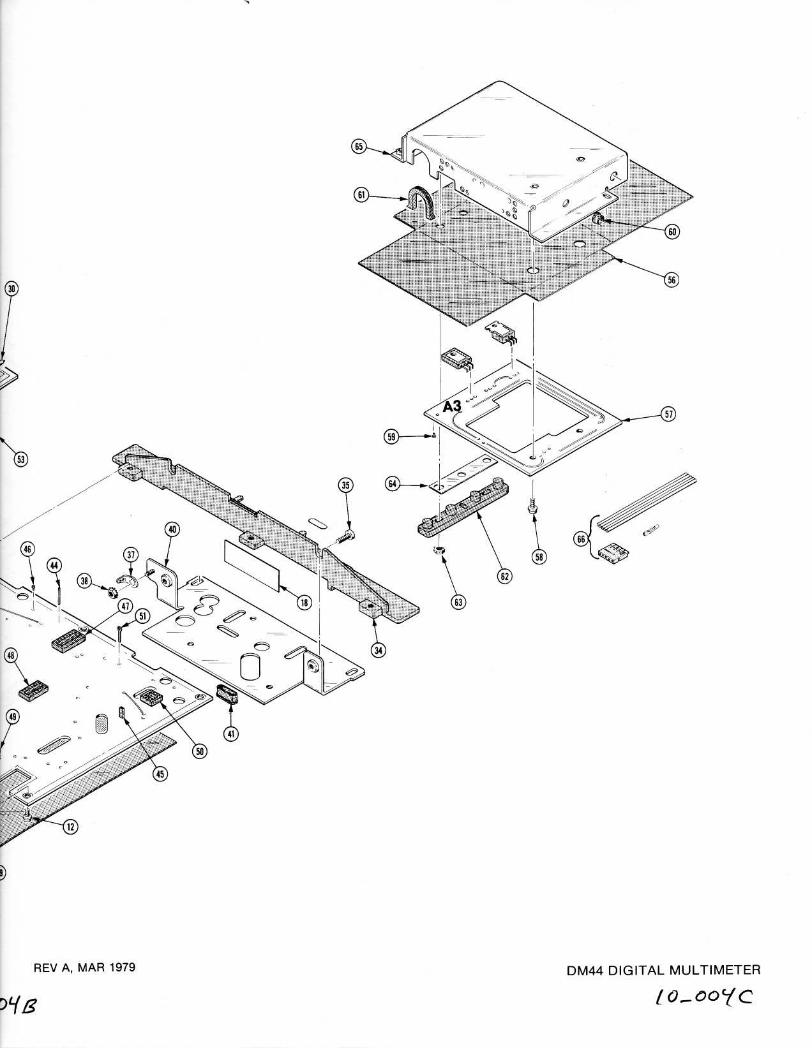
672-0482-00 1 CKT BOARD ASSY :POWER SUPPLY 80009 672-0482-00----- ----- - (464 AND 466 ONLY)672-0453-00 1 CKT BOARD ASSY :POWER SUPPLY 80009 672-0453-00----- ----- - (465, 475 AND 475A ONLY)
-56 342-0238-00 1 . INSULATOR,PLATE : 80009 342-0238-00-57 ----- ----- 1 . CKT BOARD ASSY :PWR SUP DMM(SEE A3 REPL)
(ATTACHING PARTS)-58 211-0207-00 2 . SCR,ASSEM WSHR:4-40 X 0 .312 DOUBLE SEMS 83385 OBD
----- ----- - . CKT BOARD ASSEMBLY INCLUDES :-59 136-0252-07 9 . . SOCKET,PIN CONN :W/O DIMPLE 22526 75060-012-60 348-0055-00 1 . GROMMET,PLASTIC :0 .25 INCH DIA 80009 348-0055-00-61 348-0141-00 1 . GROMMET,PLASTIC :U-SHP,0 .625 x0 .658 INCH 80009 348-0141-00-62 343-0507-00 1 . RETAINER,XSTR : 80009 343-0507-00
(ATTACHING PARTS)-63 210-0586-00 3 . NUT,PL,ASSEM WA :4-40 X 0 .25,STL CD PL 83385 OBD
-64 342-0195-00 1 . INSULATOR,PLATE :0 .70 X 3 INCHES LONG 08530 OBD-65 441-1171-00 1 . CHASSIS,SCOPE :INVERTER 80009 441-1171-00-66 198-3066-00 1 WIRE SET,ELEC : 80009 198-3066-00
----- ----- - (464 AND 466 ONLY)198-3058-00 1 WIRE SET,ELEC : 80009 198-3058-00----- ----- - (465, 475 AND 475A ONLY)
(0,. 0DYg
37
-7
REV A, MAR 1979 DM44 DIGITAL MULTIMETER
t o_ooyc
DM44 DIGITAL MULTIMETER
I 0_ooyDREV A, MAR 191

REV A, MAR 1979
v.'
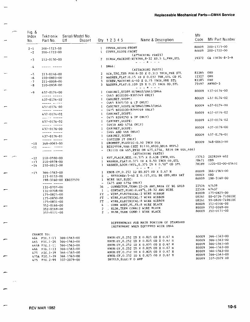
Fig . &Index
Tektronix
Serial/Model No .No .
Part No .
Eff
Dscont
REV MAR 1982
Qty 1 2 3 4 5
Name & Description
Replaceable Mechanical Parts-DM44 Service
MfrCode
Mfr Part Number
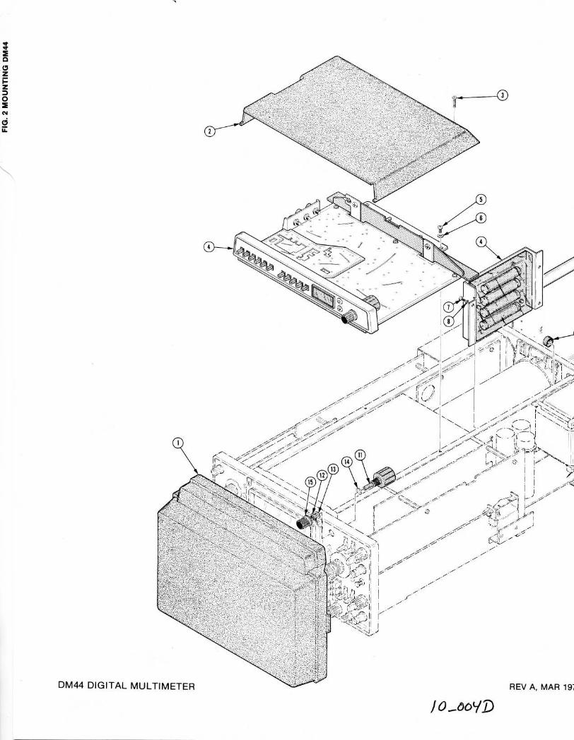
10-5
2-1 200-1723-00 1 COVER,SCOPE :FRONT 80009 200-1723-00
_2 200-1722-00 1 COVER,SCOPE :FRONT 80009 200-1722-00
(ATTACHING PARTS)
-3 212-0130-00 2 SCREW,MACHINE :W/RTNR,8- 32 X0 .5 L,PNH,STL 29372 CA 13036-8-3-8
-4 1 DM44 :(ATTACHING PARTS)
-5 213-0146-00 2 SCR,TPG,THD FOR :6-20 X 0 .313 INCH,PNH STL 83385 OBD
-6 210-0803-00 2 WASHER,FLAT :0 .15 ID X 0 .032 THK,STL CD PL 12327 OBD
_7 211-0008-00 3 SCREW,MACHINE :4-40 X 0 .25 INCH,PNH STL 83385 OBD
_8 210-0938-00 3 WASHER,FLAT :0 .109 ID X 0 .25 INCH OD,STL 75497 AN960-3
-9 437-0174-00 1 CABINET,SCOPE :W/DM40/DM43/DM44 80009 437-0174-00
- (465 B010100-B305749 ONLY)437-0174-02 1 CABINET,SCOPE : 80009 437-0174-02
- (465 B305750 & UP ONLY)
437-0174-00 1 CABINET,SCOPE :W/DM40/DM43/DM44 80009 437-0174-00
- (475 B010100-B269249 ONLY)437-0174-02 I CABINET,SCOPE : 80009 437-0174-02
- (475 B269250 & UP ONLY)
437-0174-02 1 CABINET,SCOPE : 80009 437-0174-02
- (465B AND 475A ONLY)437-0176-00 1 CABINET,SCOPE : 80009 437-0176-00
- (464 AND 466 ONLY)437-0176-01 1 CABINET,SCOPE : 80009 437-0176-01
- (OPTION lY ONLY)-10 348-0063-00 1 GROMMET,PLASTIC :0 .50 INCH DIA 80009 348-0063-00
-11 1 RESISTOR,VAR :(SEE R1110,R930,R816 REPL)- (R1110 ON 465,R930 ON 475,475A, R816 ON 464,466)
(ATTACHING PARTS)-12 210-0590-00 1 NUT,PLAIN,HEX . :0 .375 X 0 .438 INCH,STL 73743 2X28269-402
-13 210-0978-00 1 WASHER,FLAT :0 .375 ID X 0 .50 INCH OD,STL 78471 OBD
-14 210-0012-00 1 WASHER,LOCK :INTL,0 .375 ID X 0 .50" OD STL 78189 1220-02-00-0541C
-15 366-1563-00 1 KNOB :GY,0 .252 ID X0 .825 OD X 0 .67 H 80009 366-1563-00
213-0153-00 2 BK SKT. SETSCREW :5-40 X 0 .125,STL OXD,HEX OOOCY OBD
198-3160-00 XB022570 1 WIRE SET,ELEC : 80009 198-3160-00
- (475 AND 475A ONLY)131-0707-00 36 CU BE GOLD. CONNECTOR,TERM :22-26 AWG,BRS& 22 .526 47439
131-0708-00 1 AWG WIRE. CONTACT,ELEC :0 .48"L,28-32 22526 47437
175-0825-00 FT RIBBON. WIRE,ELECTRICAL:2 WIRE 80009 175-0825-00
175-0830-00 FT RIBBON. WIRE,ELECTRICAL:7 WIRE 08261 SS-0726-710610C
175-0831-00 FT WIRE RIBBON. WIRE,ELECTRICAL :8 08261 SS-0826-710610C
352-0166-00 4 BLACK. CONN BODY,PL,EL :8 WIRE 80009 352-0166-00
352-0169-00 2 BLACK. HLDR,TERM CONN :2 WIRE 80009 352-0169-00
352-0171-00 2 BLACK. HLDR,TERM CONN :1 WIRE 80009 352-0171-00
DIFFERENCES FOR MAIN PORTION OF STANDARDINSTRUMENT WHEN EQUIPPED WITH DM44
CHANGE TO :464 FIG.1-13 366-1563-00 KNOB :GY,0 .252 ID X 0 .825 OD X 0 .67 H 80009 366-1563-00
465 FIG.1-26 366-1563-00 KNOB :GY,0 .252 ID X 0 .825 OD X 0 .67 H 80009 366-1563-00
465B FIG .1-11 366-1563-00 KNOB :GY,0 .252 ID X 0 .825 OD X 0 .67 H 80009 366-1563-00
466 FIG .1-13 366-1563-00 KNOB :GY,0 .252 ID X 0 .825 OD X 0 .67 H 80009 366-1563-00
475 FIG .1-39 366-1563-00 KNOB :GY,0 .252 ID X 0 .825 OD X 0 .67 H 80009 366-1563-00
475A FIGJ -39 366-1563-00 KNOB :GY,0 .252 ID X 0 .825 OD X 0 .67 H 80009 366-1563-00
475 FIG .2-99 337-2079-00 SHIELD,ELEC :V 0 AMP 80009 337-2079-00
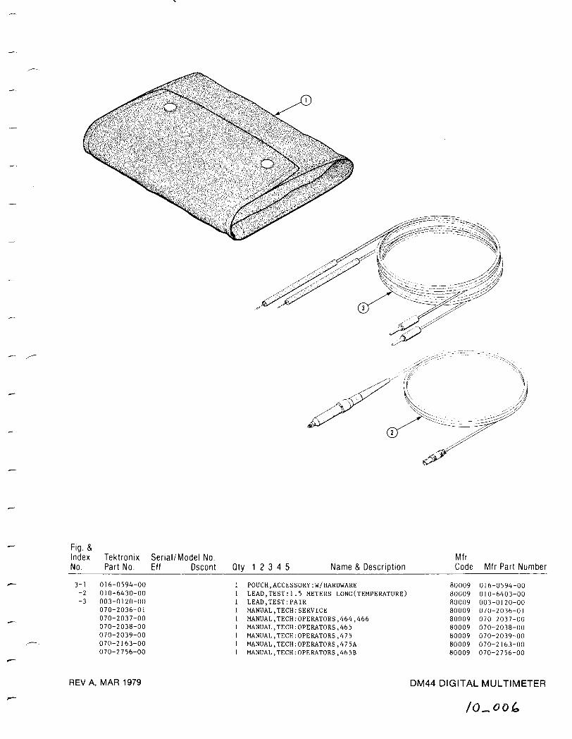
REV A, MAR 1979
DM44 DIGITAL MULTIMETER
/o-ooh
Fig . &IndexNo .
Tektronix Serial/Model No .Part No . Eff Dscont Qty 1 2 3 4 5 Name & Description
MfrCode Mfr Part Number
3-1 016-0594-00 1 POUCH,ACCESSORY :W/HARDWARE 80009 016-0594-00-2 010-6430-00 1 LEAD,TEST :1 .5 METERS LONG(TEMPERATURE) 80009 010-6403-00-3 003-0120-00 1 LEAD,TEST :PAIR 80009 003-0120-00
070-2036-01 1 MANUAL,TECH :SERVICE 80009 070-2036-01070-2037-00 1 MANUAL,TECH :OPERATORS,464,466 80009 070-2037-00070-2038-00 1 MANUAL,TECH :OPERATORS,465 80009 070-2038-00070-2039-00 1 MANUAL,TECH :OPERATORS,475 80009 070-2039-00070-2163-00 1 MANUAL,TECH :OPERATORS,475A 80009 070-2163-00070-2756-00 1 MANUAL,TECH :OPERATORS,465B 80009 070-2756-00
MANUAL CHANGE INFORMATION
At Tektronix, we continually strive to keep up with latest electronic developmentsby adding circuit and component improvements to our instruments as soon as theyare developed and tested .
Sometimes, due to printing and shipping requirements, we can't get thesechanges immediately into printed manuals. Hence, your manual may contain newchange information on following pages.
Asingle change mayaffect several sections . Since the change information sheetsare carried in the manual until all changes are permanently entered, someduplication may occur. If no such change pages appear following this page, yourmanual is correct as printed.