Stato dei Progetti Speciali SPARC e NTA-PLASMONX · • Strategy design • Approval ... •...
58
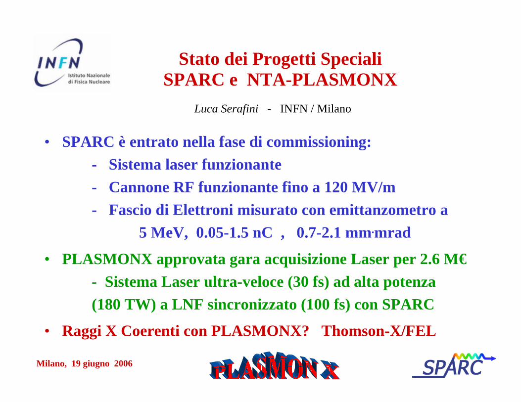
Milano, 19 giugno 2006 Stato dei Progetti Speciali SPARC e NTA-PLASMONX • SPARC è entrato nella fase di commissioning: - Sistema laser funzionante - Cannone RF funzionante fino a 120 MV/m - Fascio di Elettroni misurato con emittanzometro a 5 MeV, 0.05-1.5 nC , 0.7-2.1 mm . mrad • PLASMONX approvata gara acquisizione Laser per 2.6 M€ - Sistema Laser ultra-veloce (30 fs) ad alta potenza (180 TW) a LNF sincronizzato (100 fs) con SPARC • Raggi X Coerenti con PLASMONX? Thomson-X/FEL Luca Serafini - INFN / Milano
Transcript of Stato dei Progetti Speciali SPARC e NTA-PLASMONX · • Strategy design • Approval ... •...
Milano, 19 giugno 2006
Stato dei Progetti SpecialiSPARC e NTA-PLASMONX
• SPARC è entrato nella fase di commissioning:- Sistema laser funzionante- Cannone RF funzionante fino a 120 MV/m- Fascio di Elettroni misurato con emittanzometro a
5 MeV, 0.05-1.5 nC , 0.7-2.1 mm.mrad
• PLASMONX approvata gara acquisizione Laser per 2.6 M€- Sistema Laser ultra-veloce (30 fs) ad alta potenza (180 TW) a LNF sincronizzato (100 fs) con SPARC
• Raggi X Coerenti con PLASMONX? Thomson-X/FEL
Luca Serafini - INFN / Milano
Milano, 19 giugno 2006
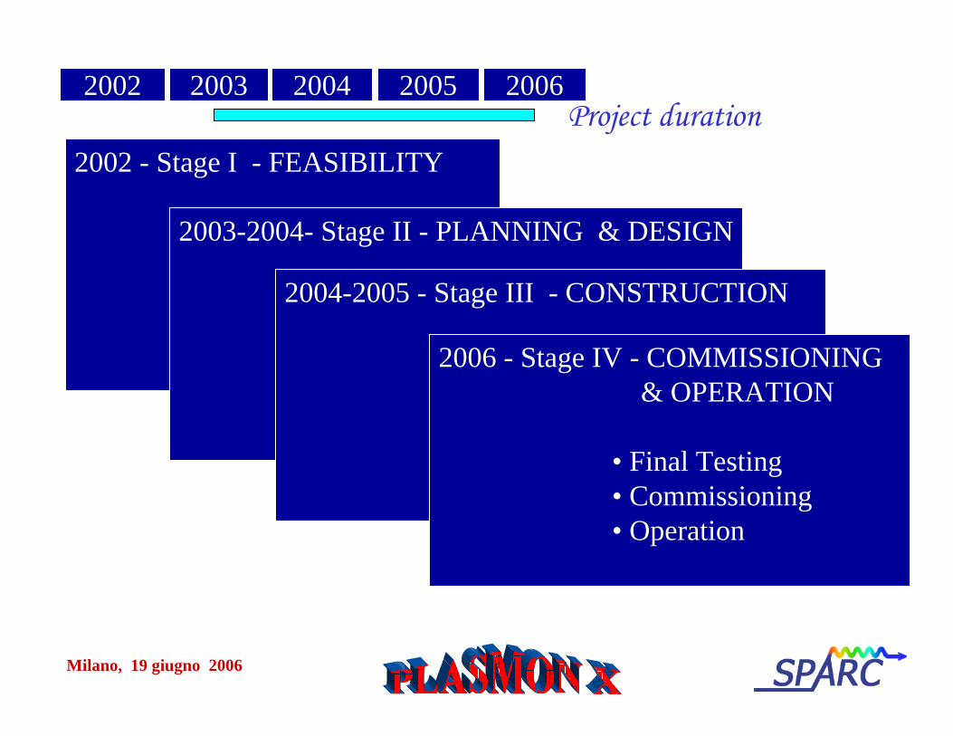
2002 - Stage I - FEASIBILITY
• Project formulation • Feasibility Study• Strategy design• Approval
2003-2004- Stage II - PLANNING & DESIGN
• Base design• Detailed Cost and schedule• Detailed planning• Major contracts for procurement
2004-2005 - Stage III - CONSTRUCTION
• Manufacturing • Delivery• Civil works• Installation
2006 - Stage IV - COMMISSIONING & OPERATION
• Final Testing• Commissioning• Operation
2002 2003 2004 2005 2006Project duration
Milano, 19 giugno 2006
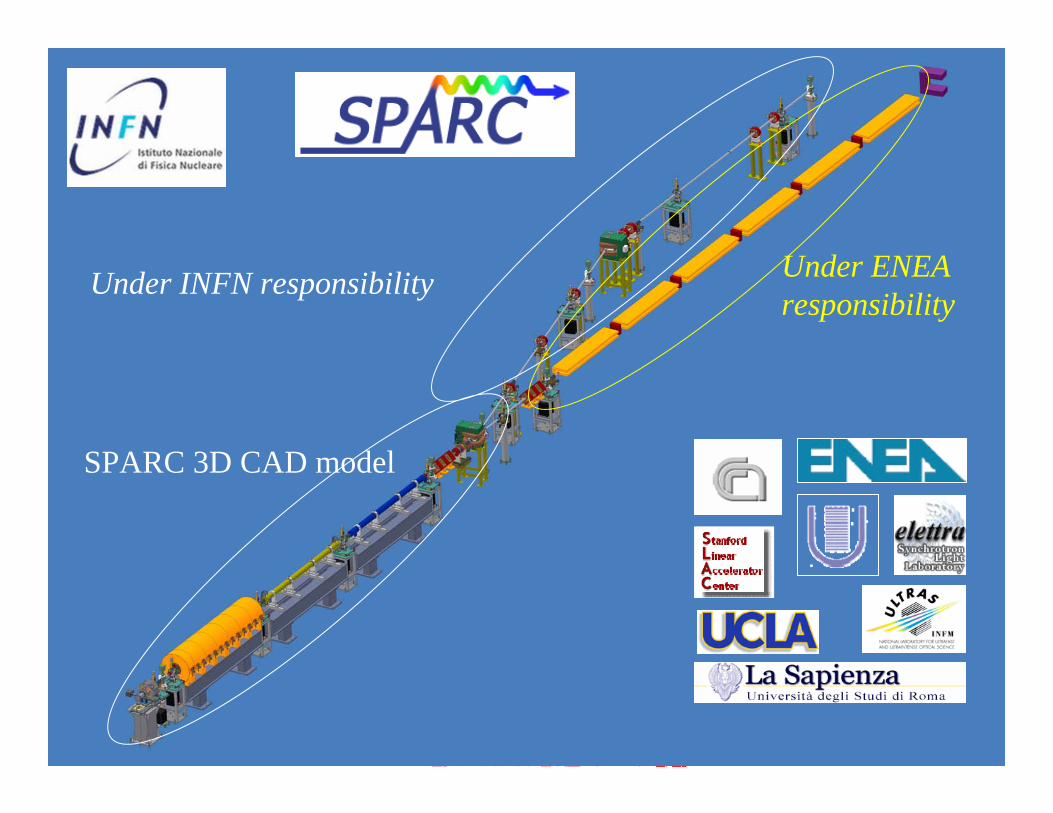
Under INFN responsibility
SPARC 3D CAD model
Under ENEAresponsibility
Milano, 19 giugno 2006
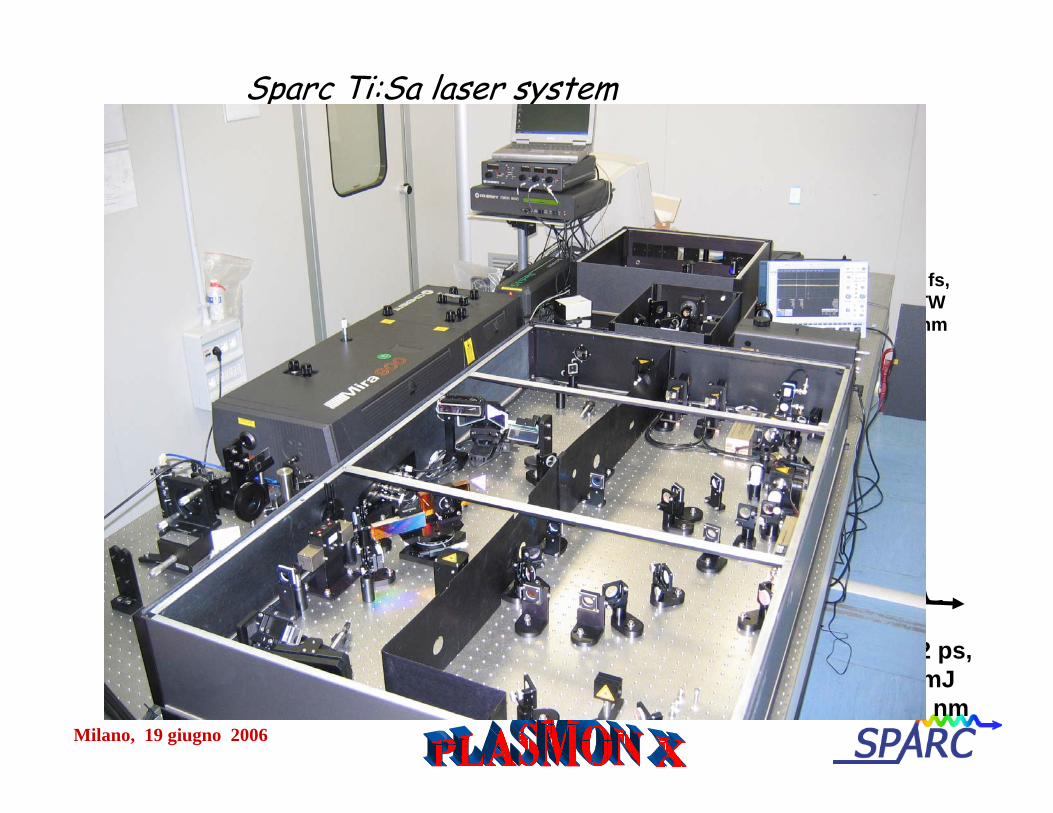
Sparc Ti:Sa laser system
RegenRegen + 2 + 2 mpassmpassAmplifierAmplifier
MiraMira
oscillatoroscillator
VerdiVerdiPumpPump
EvolutionEvolutionPump 1Pump 1
100 fspulse, low
energy
>105 fs, 0.5 TW800 nm
5 W CW
ContinuumContinuumPump 2Pump 2
10 ns560 mJ532 nm
AO AO pulse pulse
shapershaper
100 ns7 mJ 532 nm
THGTHG
UV stretcherUV stretcher
5-12 ps, 1 mJ
266 nm
Milano, 19 giugno 2006
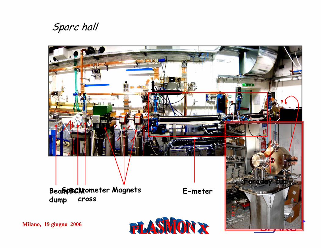
Faraday cupE-meterMagnetsSpectrometer
crossBCMBeam
dump
Sparc hall
Milano, 19 giugno 2006
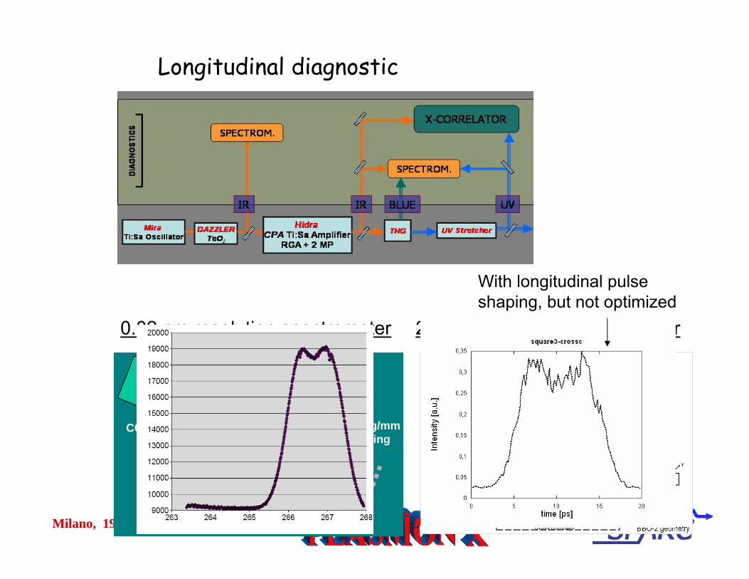
Longitudinal diagnostic
0.02 nm resolution spectrometer
30 cm lens
4350 g/mmgrating
CCD
UV beam
200 fs resolution UV xcorrelator
With longitudinal pulseshaping, but not optimized

Milano, 19 giugno 2006
QE & transverse uniformity
•In order to have uniform density beam charge distribution a uniform QE and a uniform transv. profile are needed
•QE map done by scanning cathode surface with a small beam (100 um)and looking at the charge on the faraday cup.
•Red zone is the higher QE zone, and it’s also the actual working point, so cathode has been cleaned during operations.
•To run at higher charge we need bigger laser spot sizes• Lot of work has been done on transverse laser uniformity • Charge is variable (min=50pC , max=1.5nC)
LASER CLEANING
5107 −= xQE
0.3X0.26 mm rms
Milano, 19 giugno 2006
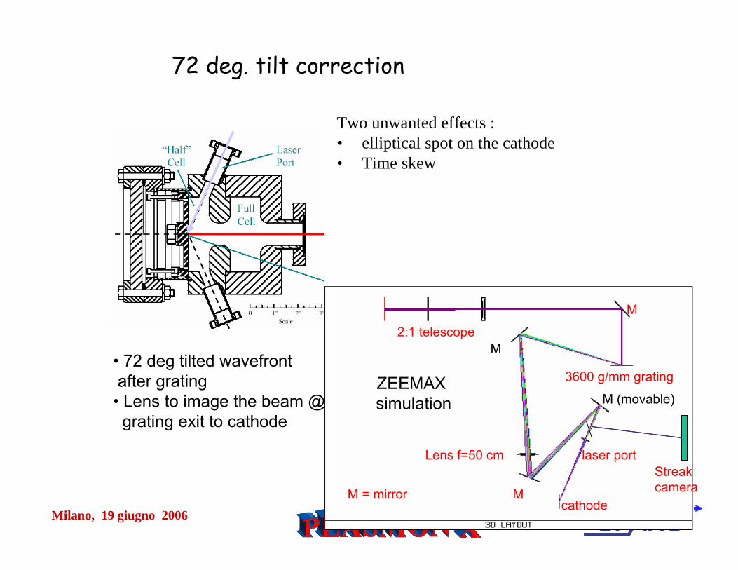
Two unwanted effects :• elliptical spot on the cathode• Time skew
2:1 telescope
3600 g/mm grating
Lens f=50 cm
M = mirror
M
M
M (movable)
laser port
Mcathode
Streakcamera
72 deg. tilt correction
ZEEMAX simulation
• 72 deg tilted wavefrontafter grating• Lens to image the beam @grating exit to cathode
Milano, 19 giugno 2006
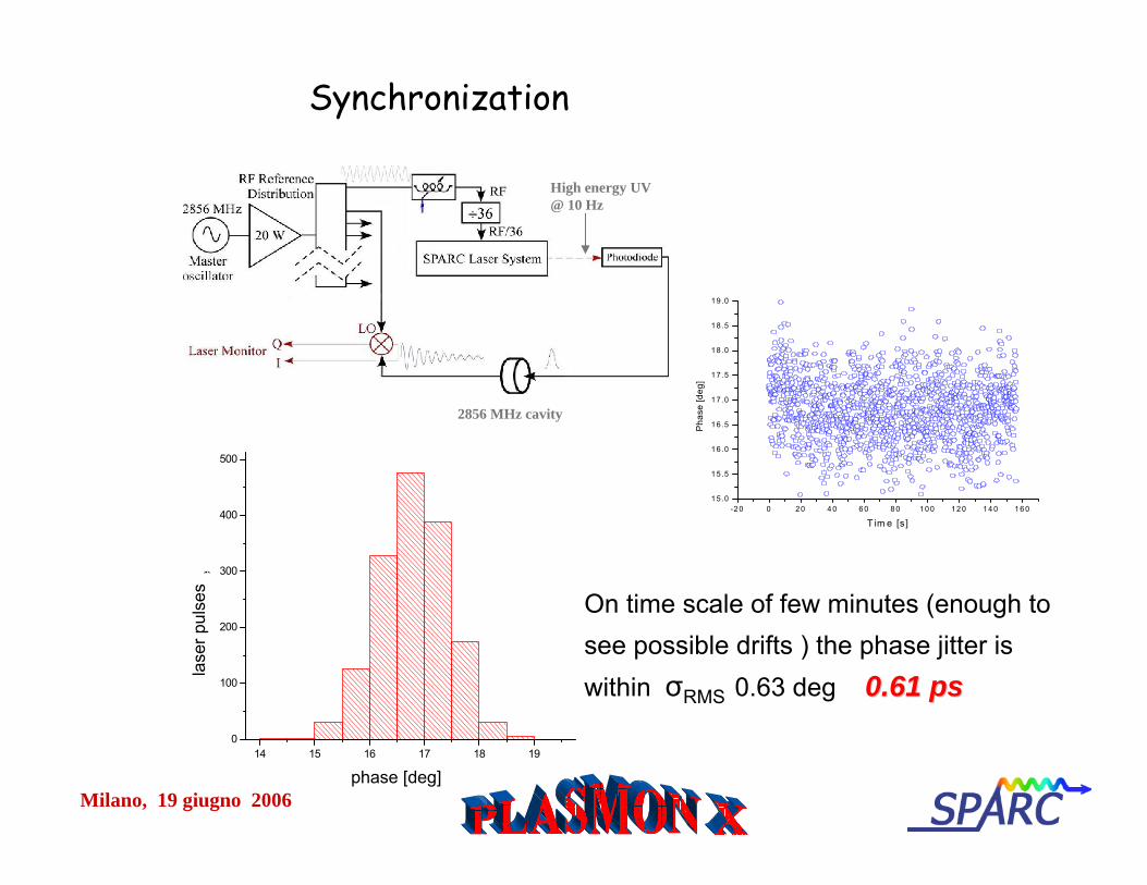
Synchronization
-20 0 20 40 60 80 100 120 140 16015 .0
15 .5
16 .0
16 .5
17 .0
17 .5
18 .0
18 .5
19 .0
Pha
se [d
eg]
T im e [s]
2856 MHz cavity
High energy UV @ 10 Hz
On time scale of few minutes (enough to see possible drifts ) the phase jitter is within σRMS 0.63 deg 0.61 0.61 psps
14 15 16 17 18 190
100
200
300
400
500
Y A
xis
Title
X Axis Titlephase [deg]
lase
r pul
ses
Milano, 19 giugno 2006
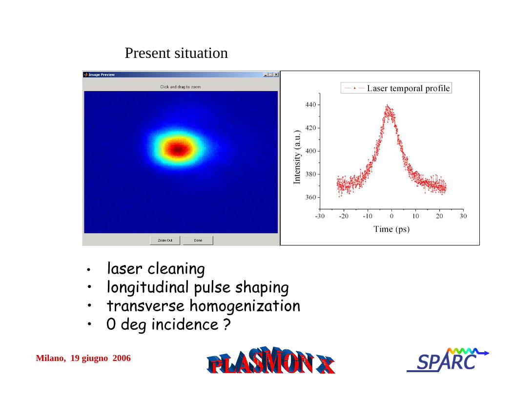
Present situation
• Energy ok• Gaussian transverse and longitudinal profile (dazzler in
autocompensation mode) • tilt compensation works but critical
Future plans
• laser cleaning• longitudinal pulse shaping• transverse homogenization• 0 deg incidence ?
Milano, 19 giugno 2006
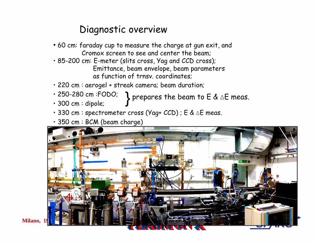
Diagnostic overview• 60 cm: faraday cup to measure the charge at gun exit, and
Cromox screen to see and center the beam;• 85-200 cm: E-meter (slits cross, Yag and CCD cross);
Emittance, beam envelope, beam parametersas function of trnsv. coordinates;
• 220 cm : aerogel + streak camera; beam duration;• 250-280 cm :FODO; • 300 cm : dipole; • 330 cm : spectrometer cross (Yag+ CCD) ; E & ΔE meas.• 350 cm : BCM (beam charge)
} prepares the beam to E & ΔE meas.
Milano, 19 giugno 2006
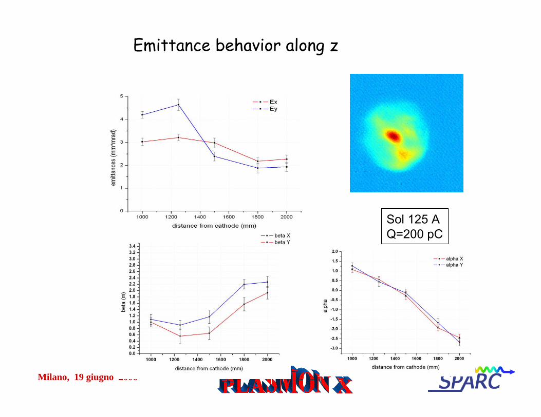
Sol 125 AQ=200 pC
Emittance behavior along z
Milano, 19 giugno 2006
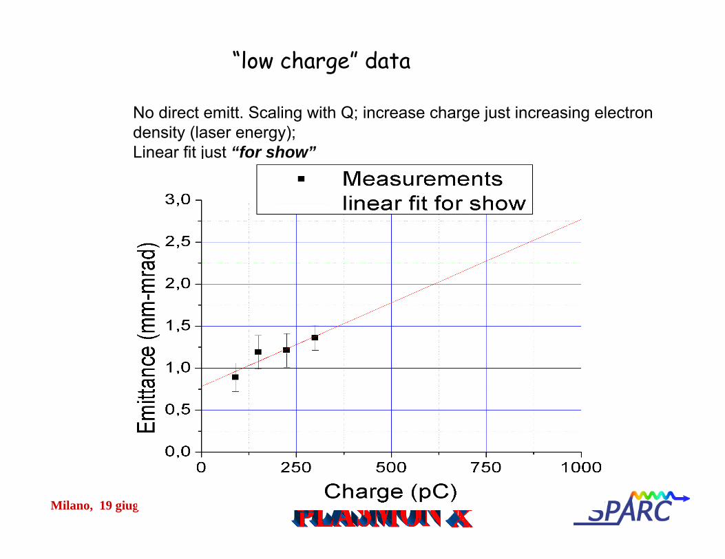
No direct emitt. Scaling with Q; increase charge just increasing electron density (laser energy);Linear fit just “for show”
“low charge” data
Milano, 19 giugno 2006
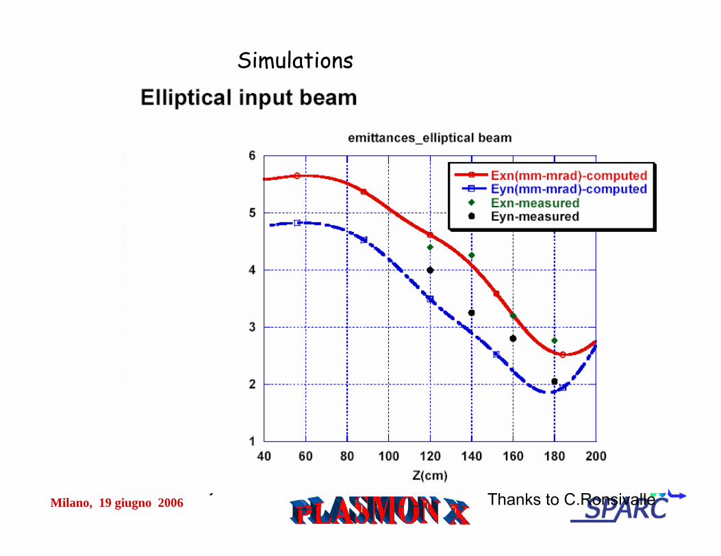
Simulations
Thanks to C.Ronsivalle
Milano, 19 giugno 2006
Conclusions & future plans
• Best achieved results– 2.1 mm-mrad @ 700 pC , 10 ps– 0.7 mm-mrad @ 160 pC, 10 ps
• More work on laser beam• Understanding dipole and quadrupole components in solenoid (mask,
different fields in each coil and different configurations,…)• high charge (up to 1.1 nC) emittance measurements• Comparison with simulation ongoing (next step real transverse and
longitudinal profile) • Main linac installation scheduled to start in the summer
Milano, 19 giugno 2006
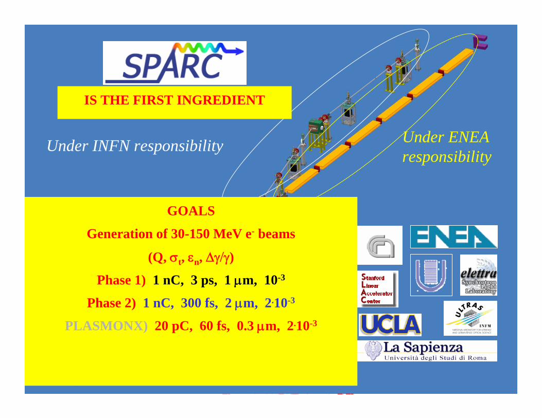
Under INFN responsibility Under ENEAresponsibility
IS THE FIRST INGREDIENT
GOALS
Generation of 30-150 MeV e- beams
(Q, σt, εn, Δγ/γ)
Phase 1) 1 nC, 3 ps, 1 μm, 10-3
Phase 2) 1 nC, 300 fs, 2 μm, 2.10-3
PLASMONX) 20 pC, 60 fs, 0.3 μm, 2.10-3
Milano, 19 giugno 2006
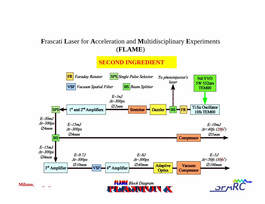
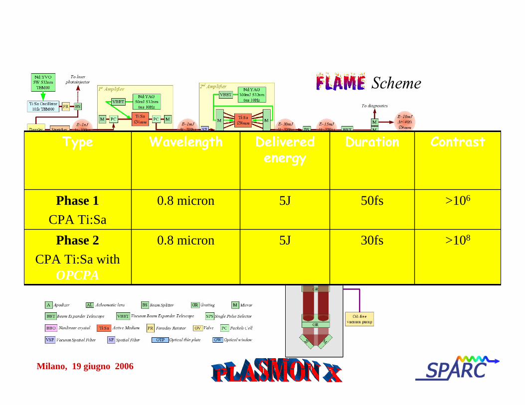
Frascati Laser for Acceleration and Multidisciplinary Experiments (FLAME)
SECOND INGREDIENT
Milano, 19 giugno 2006
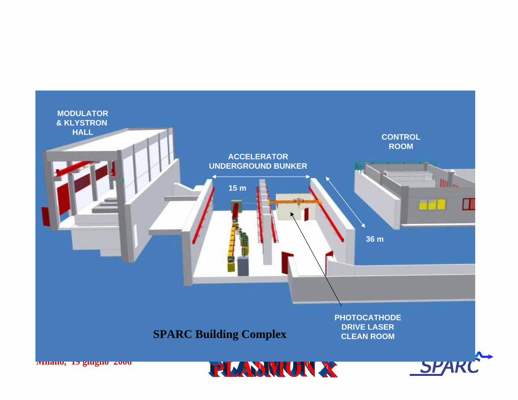
SPARC Building Complex
CONTROLROOM
ACCELERATORUNDERGROUND BUNKER
MODULATOR& KLYSTRON
HALL
15 m
36 m
PHOTOCATHODEDRIVE LASERCLEAN ROOM
Milano, 19 giugno 2006
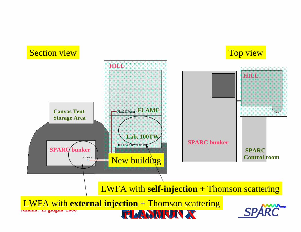
SPARC bunker
HILL
SPARCControl room
SPARC bunker
HILL
FLAME
Lab. 100TW
Canvas TentStorage Area
Top viewSection view
New building
LWFA with self-injection + Thomson scatteringLWFA with external injection + Thomson scattering
Milano, 19 giugno 2006
>108
>106
Contrast
30fs5J0.8 micronPhase 2CPA Ti:Sa with
OPCPA
50fs5J0.8 micronPhase 1CPA Ti:Sa
DurationDeliveredenergy
WavelengthType
Milano, 19 giugno 2006
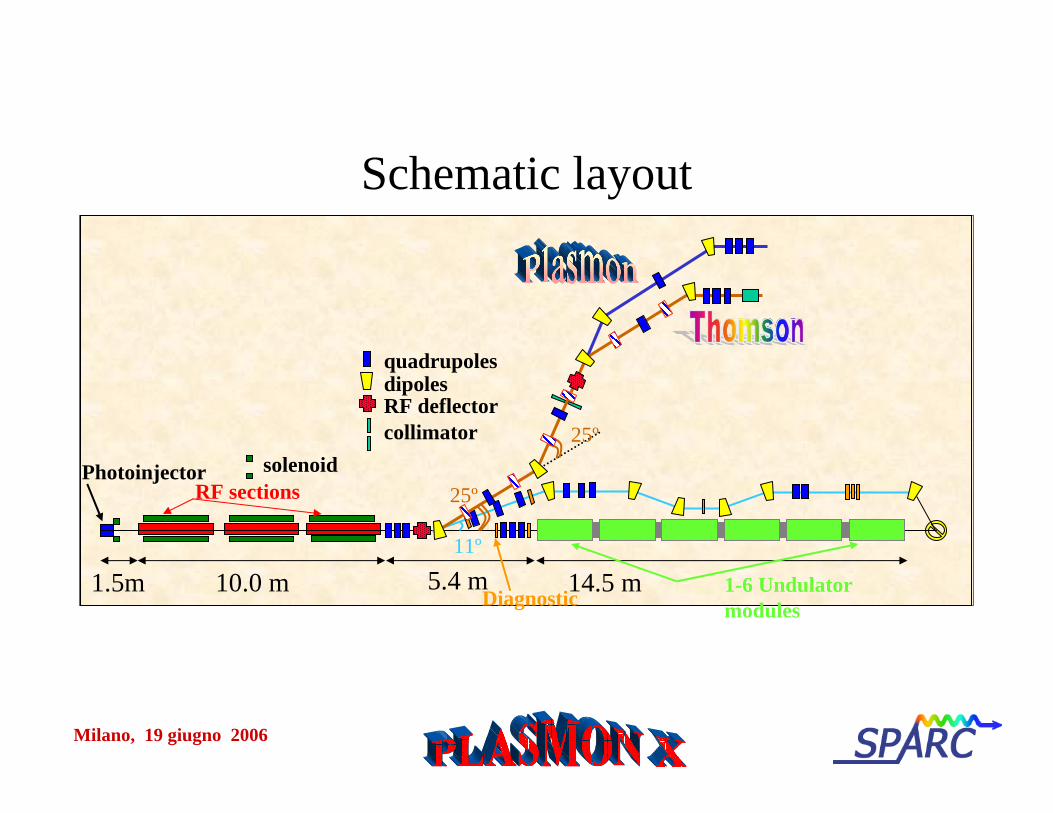
Schematic layout
14.5 m1.5m11º
10.0 m 5.4 m
quadrupolesdipoles
Diagnostic 1-6 Undulator modules
Photoinjector solenoidRF sections
RF deflectorcollimator
25º
25º

Milano, 19 giugno 2006
Experimental set-up for the generation of tunable X-ray radiation via Thomson scattering of optical photons by relativistic electron bunches
Milano, 19 giugno 2006
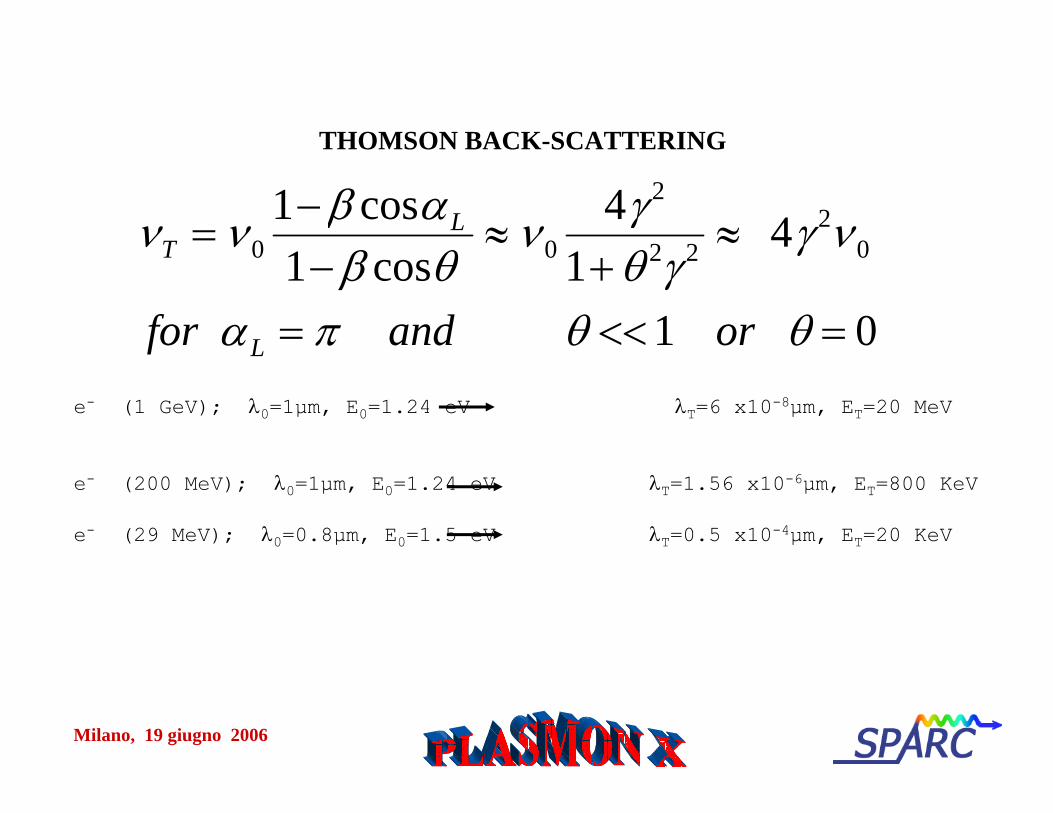
THOMSON BACK-SCATTERING
e- (1 GeV); λ0=1µm, E0=1.24 eV λT=6 x10⁻⁸µm, ET=20 MeV
e- (200 MeV); λ0=1µm, E0=1.24 eV λT=1.56 x10⁻⁶µm, ET=800 KeV
e- (29 MeV); λ0=0.8µm, E0=1.5 eV λT=0.5 x10⁻⁴µm, ET=20 KeV
νT = ν 01− β cosαL
1− β cosθ≈ ν 0
4γ 2
1+ θ 2γ 2 ≈ 4γ 2ν 0
for αL = π and θ <<1 or θ = 0
Milano, 19 giugno 2006
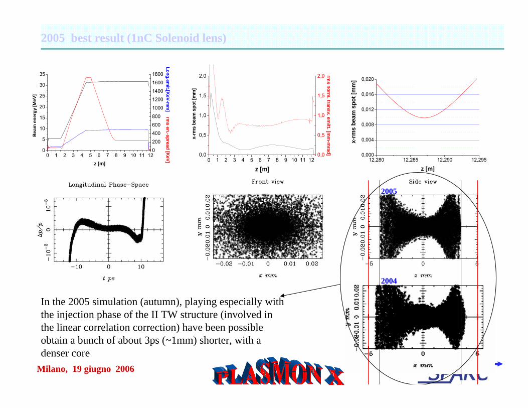
2005 best result (1nC Solenoid lens)
0 1 2 3 4 5 6 7 8 9 10 11 120
5
10
15
20
25
30
35
Bea
m e
nerg
y [M
eV]
z [m]
0
200
400
600
800
1000
1200
1400
1600
1800
Long.emit.[K
eV-mm
] rms en.-spread [K
eV] 0 1 2 3 4 5 6 7 8 9 10 11 120,0
0,5
1,0
1,5
2,0
x-rm
s be
am s
pot [
mm
]
z [m]
0,0
0,5
1,0
1,5
2,0
rms norm
. transv. emitt. [m
m-m
rad]
12,280 12,285 12,290 12,2950,000
0,004
0,008
0,012
0,016
0,020
x-rm
s be
am s
pot [
mm
]
z [m]
In the 2005 simulation (autumn), playing especially with the injection phase of the II TW structure (involved in the linear correlation correction) have been possible obtain a bunch of about 3ps (~1mm) shorter, with a denser core
2005
2004
Milano, 19 giugno 2006
Angular and spectral distribution of the TS radiation in the case of an unguided 3 ps laser pulse (12.5 µm beam waist)
Incoherent spontaneous radiation
QuickTime™ and aTIFF (Uncompressed) decompressor
are needed to see this picture.
Milano, 19 giugno 2006
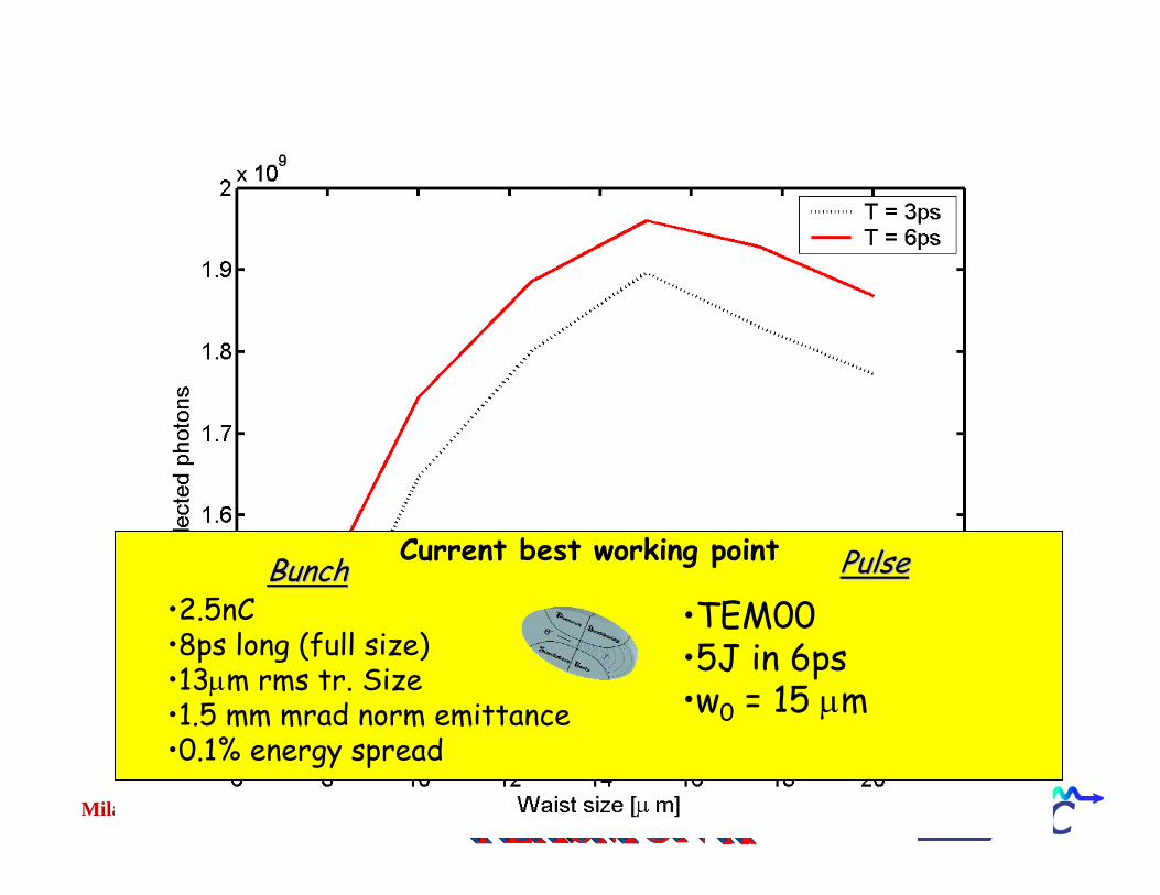
High Flux operation mode
Current best working point PulsePulse•2.5nC•8ps long (full size)•13μm rms tr. Size•1.5 mm mrad norm emittance•0.1% energy spread
BunchBunch•TEM00•5J in 6ps•w0 = 15 μm
Milano, 19 giugno 2006
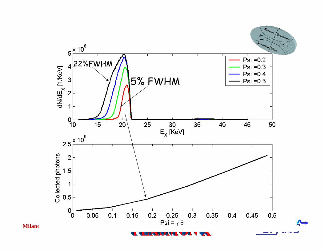
22%FWHM
5% FWHM
Milano, 19 giugno 2006
QuickTime™ and aTIFF (Uncompressed) decompressor
are needed to see this picture.
Milano, 19 giugno 2006
QuickTime™ and aTIFF (Uncompressed) decompressor
are needed to see this picture.
Milano, 19 giugno 2006
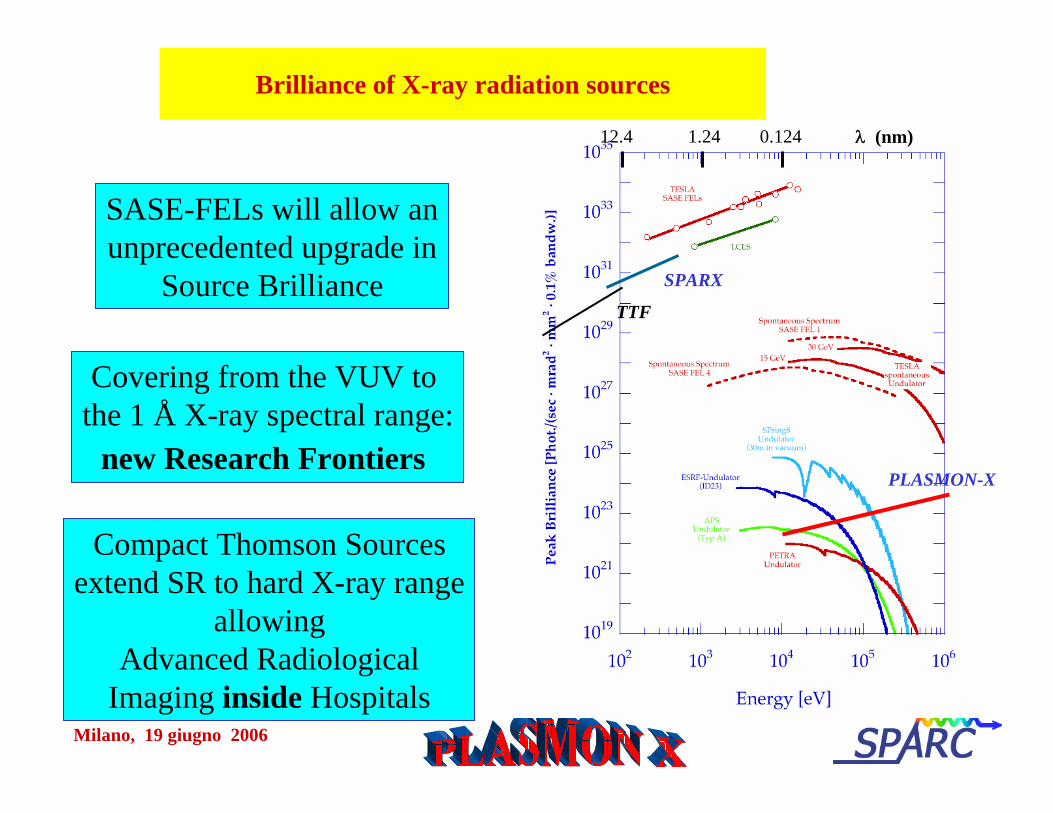
SASE-FELs will allow anunprecedented upgrade in
Source Brilliance
Covering from the VUV to the 1 Å X-ray spectral range:
new Research Frontiers
SPARX
TTF
12.4 1.24 0.124 λ (nm)
PLASMON-X
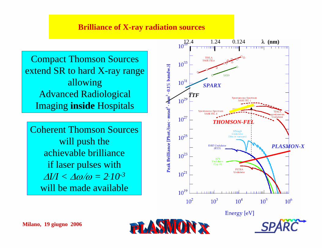
Compact Thomson Sourcesextend SR to hard X-ray range
allowingAdvanced Radiological
Imaging inside Hospitals
Brilliance of X-ray radiation sources
Milano, 19 giugno 2006
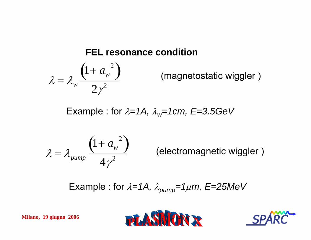
FEL resonance condition
λ = λw
1+ aw2( )
2γ 2(magnetostatic wiggler )
λ = λpump
1+ aw2( )
4γ 2(electromagnetic wiggler )
Example : for λ=1A, λw=1cm, E=3.5GeV
Example : for λ=1A, λpump=1μm, E=25MeV
Milano, 19 giugno 2006
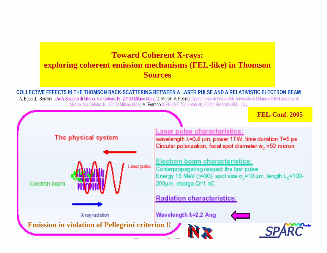
Toward Coherent X-rays:exploring coherent emission mechanisms (FEL-like) in Thomson
Sources
FEL-Conf. 2005
Emission in violation of Pellegrini criterion !!
Milano, 19 giugno 2006
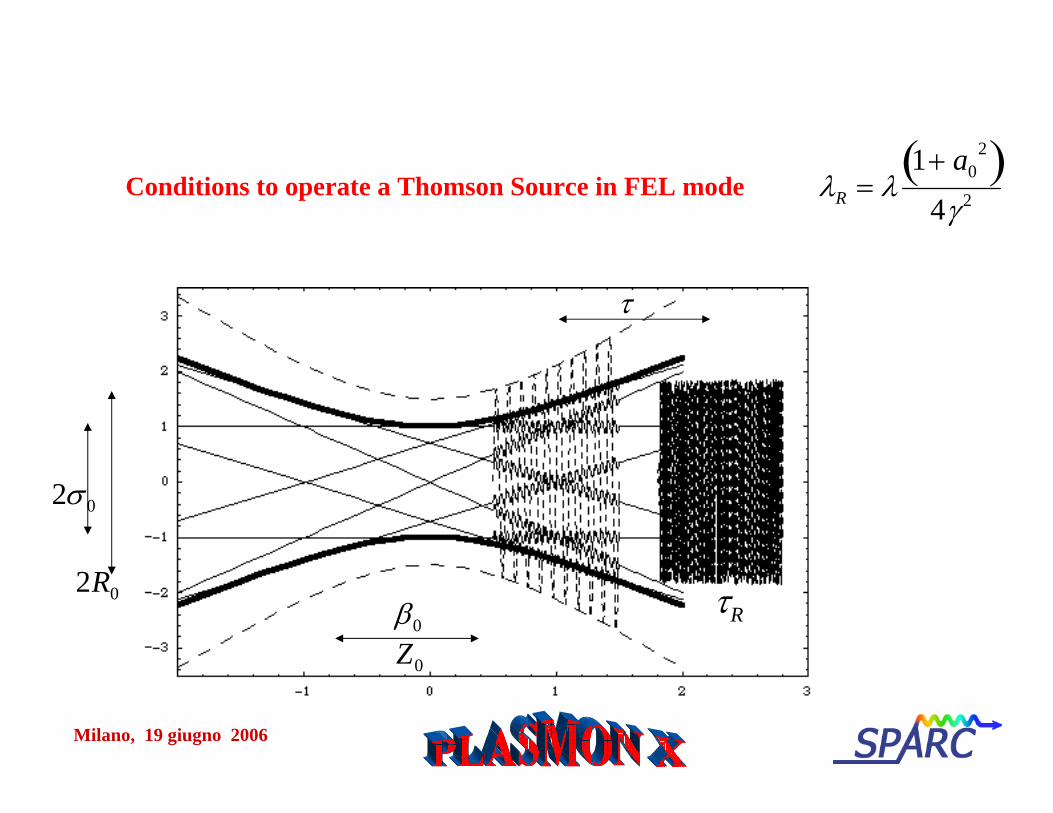
Conditions to operate a Thomson Source in FEL mode λR = λ1+ a0
2( )4γ 2
2σ 0
2R0β0
Z0
τ
τR
Milano, 19 giugno 2006
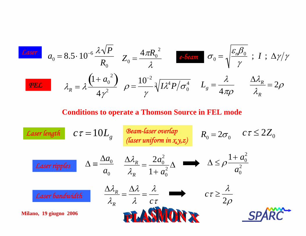
Conditions to operate a Thomson Source in FEL mode
Beam-laser overlap(laser uniform in x,y,z)
cτ =10LgLaser length
λR = λ1+ a0
2( )4γ 2
a0 = 8.5 ⋅10−6 λ PR0
Laser
FEL ρ =10−2
γIλ4P σ 0
43
Z0 =4πR0
2
λe-beam σ 0 =
εnβ0
γ ; I ; Δγ γ
ΔλR
λR
= 2ρLg =λ
4πρ
Laser ripples
R0 = 2σ 0
Δ ≡Δa0
a0
ΔλR
λR
=2a0
2
1+ a02 Δ Δ ≤ ρ1+ a0
2
a02
cτ ≤ 2Z0
Laser bandwidthΔλR
λR
=Δλλ
=λcτ
cτ ≥λ
2ρ
Milano, 19 giugno 2006
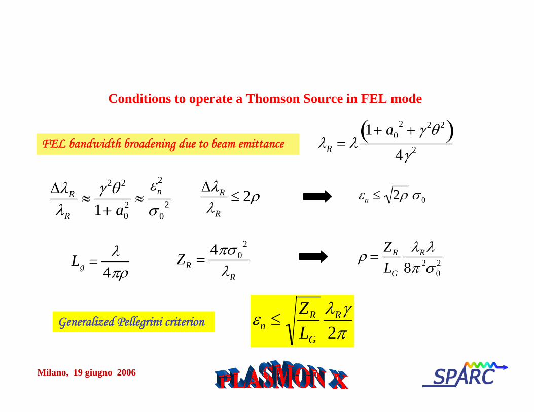
Generalized Pellegrini criterion
Conditions to operate a Thomson Source in FEL mode
FEL bandwidth broadening due to beam emittance
εn ≤ZR
LG
λRγ2π
ZR =4πσ 0
2
λR
λR = λ1+ a0
2 + γ 2θ 2( )4γ 2
ΔλR
λR
≈γ 2θ 2
1+ a02 ≈
εn2
σ 02
εn ≤ 2ρ σ 0ΔλR
λR
≤ 2ρ
ρ =ZR
LG
λR λ8π 2σ 0
2Lg =λ
4πρ
Milano, 19 giugno 2006
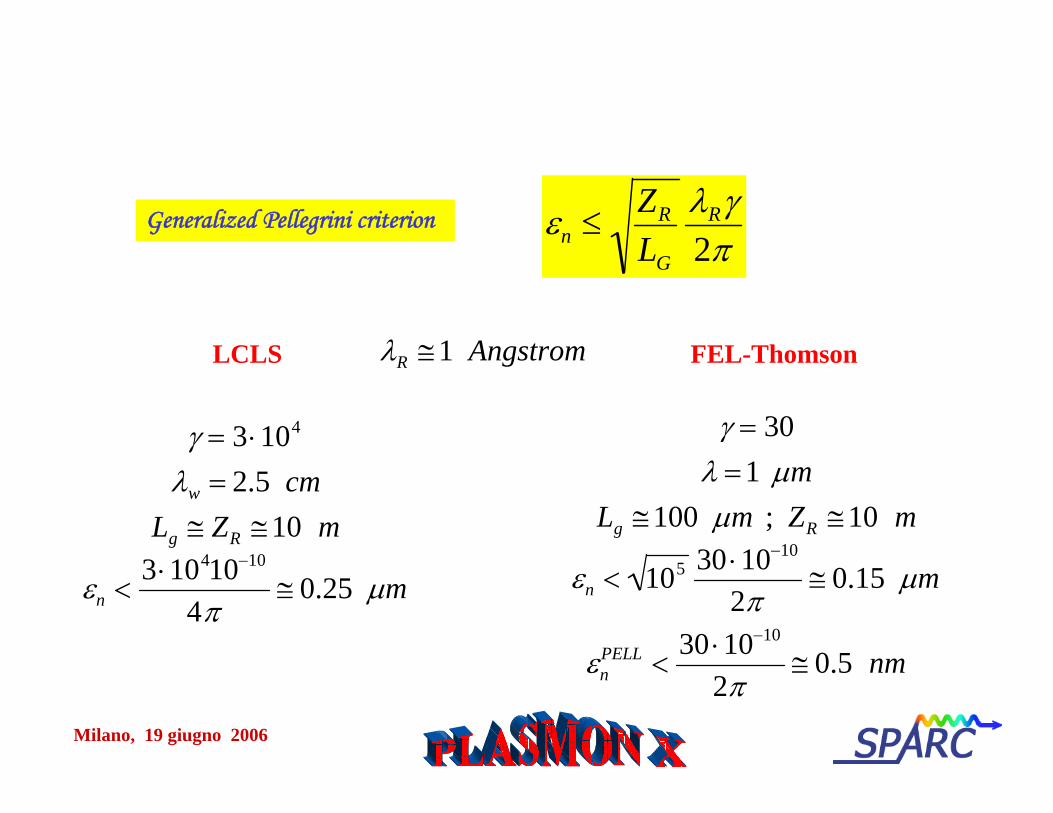
Generalized Pellegrini criterion εn ≤ZR
LG
λRγ2π
LCLS
γ = 3 ⋅104
λw = 2.5 cmLg ≅ ZR ≅10 m
εn <3 ⋅10410−10
4π≅ 0.25 μm
FEL-ThomsonλR ≅1 Angstrom
γ = 30λ =1 μm
Lg ≅100 μm ; ZR ≅10 m
εn < 105 30 ⋅10−10
2π≅ 0.15 μm
εnPELL <
30 ⋅10−10
2π≅ 0.5 nm
Milano, 19 giugno 2006
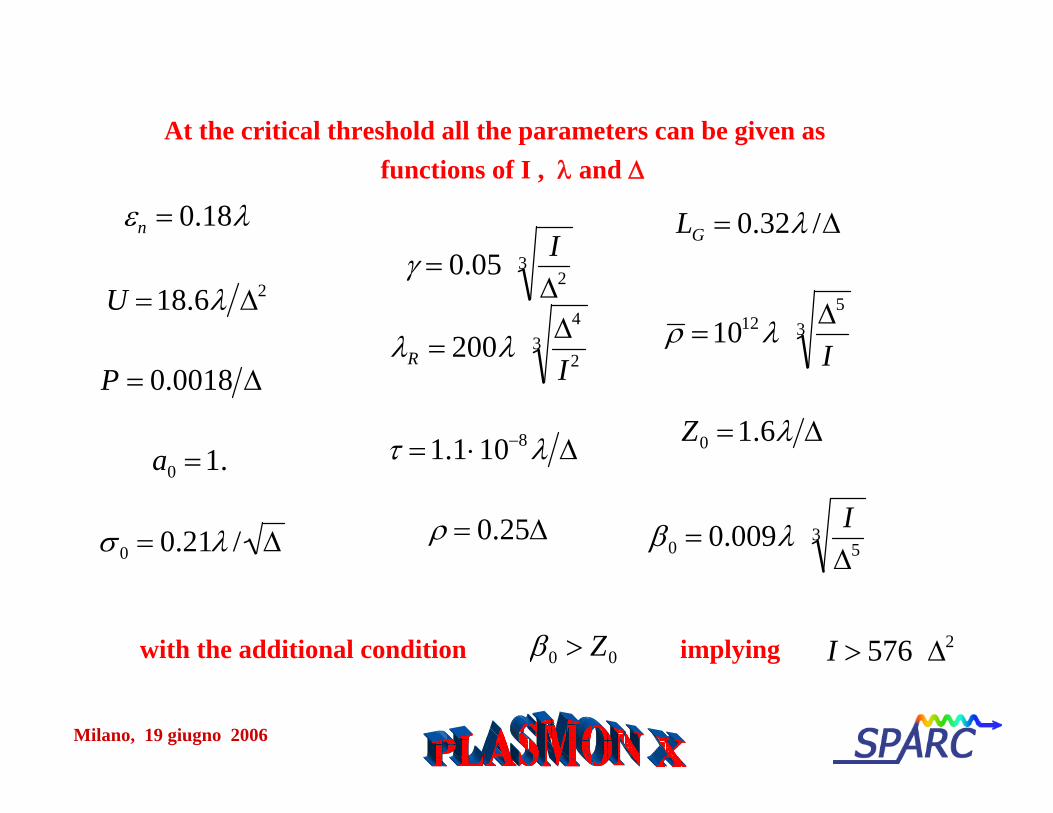
εn = 0.18λ
U =18.6λ Δ2
P = 0.0018 Δ
a0 =1.
At the critical threshold all the parameters can be given as functions of I , λ and Δ
γ = 0.05 IΔ2
3
λR = 200λ Δ4
I23
τ =1.1⋅10−8 λ Δ
ρ = 0.25Δ
LG = 0.32λ /Δ
ρ =1012 λ Δ5
I3
Z0 =1.6λ Δ
β0 = 0.009λ IΔ5
3σ 0 = 0.21λ / Δ
I > 576 Δ2with the additional condition β0 > Z0 implying
Milano, 19 giugno 2006
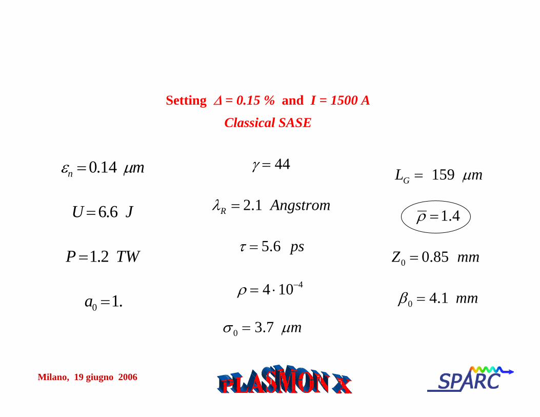
εn = 0.14 μm
U = 6.6 J
P =1.2 TW
a0 =1.
Setting Δ = 0.15 % and I = 1500 A
Classical SASE
γ = 44
λR = 2.1 Angstrom
τ = 5.6 ps
ρ = 4 ⋅10−4
LG = 159 μm
ρ =1.4
Z0 = 0.85 mm
β0 = 4.1 mm
σ 0 = 3.7 μm
Milano, 19 giugno 2006
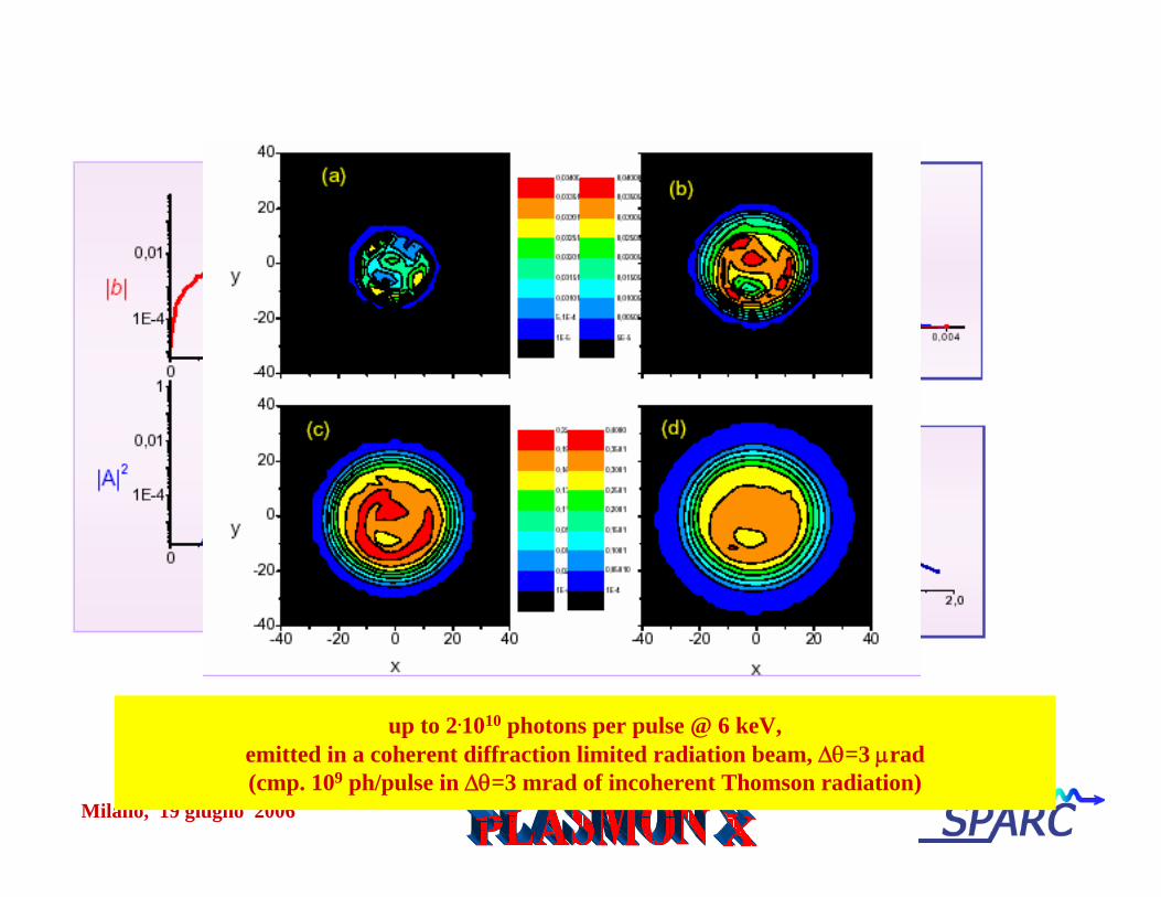
up to 2.1010 photons per pulse @ 6 keV,emitted in a coherent diffraction limited radiation beam, Δθ=3 μrad(cmp. 109 ph/pulse in Δθ=3 mrad of incoherent Thomson radiation)
Milano, 19 giugno 2006
SPARX
TTF
12.4 1.24 0.124 λ (nm)
PLASMON-X
Compact Thomson Sourcesextend SR to hard X-ray range
allowingAdvanced Radiological
Imaging inside Hospitals
Brilliance of X-ray radiation sources
THOMSON-FELCoherent Thomson Sources
will push theachievable brillianceif laser pulses with
ΔI/I < Δω/ω = 2.10-3
will be made available
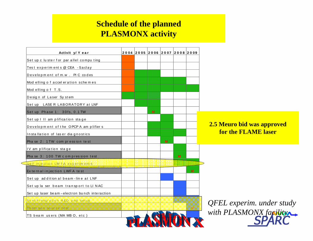
Schedule of the plannedPLASMONX activity
Activit y/Y ear 2004 2005 2006 2007 2008 2009
Set up c lu ste r f or par a llel compu ting
Tes t experim ent s @ CEA -Saclay
Developm ent o f m.w . PI C co des
Mod elling o f accel era tion sche m es
Mod elling o f T .S.
Desig n of Laser Sy stem
Set up LASE R LABORATORY a t LNF
Set up Phase 1 : 30fs, 0 .1 TW M
Set up I II am p lifica tion sta ge
Developm ent o f t he OPCP A am p lifier s
Insta lla tion of las er dia gnostics
Pha se 2 : 1TW com pr ess ion te st M
IV am p lifica tion sta ge
Pha se 3 : 100 TW c om pres sion test M
Se lf inje ction LW FA experim ent s
Ex te rn a l i n jec tion LWF A te st M
Set up ad d ition a l beam -lin e a t LNF
Set up la ser b eam tra nsp ort to LI NAC
Set up laser beam–electron bunch interaction
Sy nc hroniz a tion R&D and setup
Th om so n so ur ce test M
TS bea m us ers (MA MB O, etc )
2.5 Meuro bid was approvedfor the FLAME laser
QFEL experim. under studywith PLASMONX facility
Milano, 19 giugno 2006
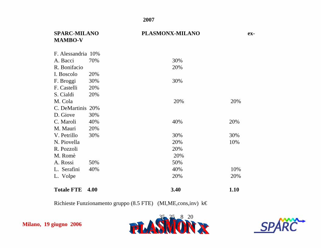
2007
SPARC-MILANO PLASMONX-MILANO ex-MAMBO-V
F. Alessandria 10% A. Bacci 70% 30%R. Bonifacio 20%I. Boscolo 20%F. Broggi 30% 30%F. Castelli 20%S. Cialdi 20%M. Cola 20% 20%C. DeMartinis 20% D. Giove 30% C. Maroli 40% 40% 20%M. Mauri 20% V. Petrillo 30% 30% 30%N. Piovella 20% 10%R. Pozzoli 20%M. Romè 20%A. Rossi 50% 50%L. Serafini 40% 40% 10%L. Volpe 20% 20%
Totale FTE 4.00 3.40 1.10
Richieste Funzionamento gruppo (8.5 FTE) (MI,ME,cons,inv) k€
35 25 8 20
Milano, 19 giugno 2006
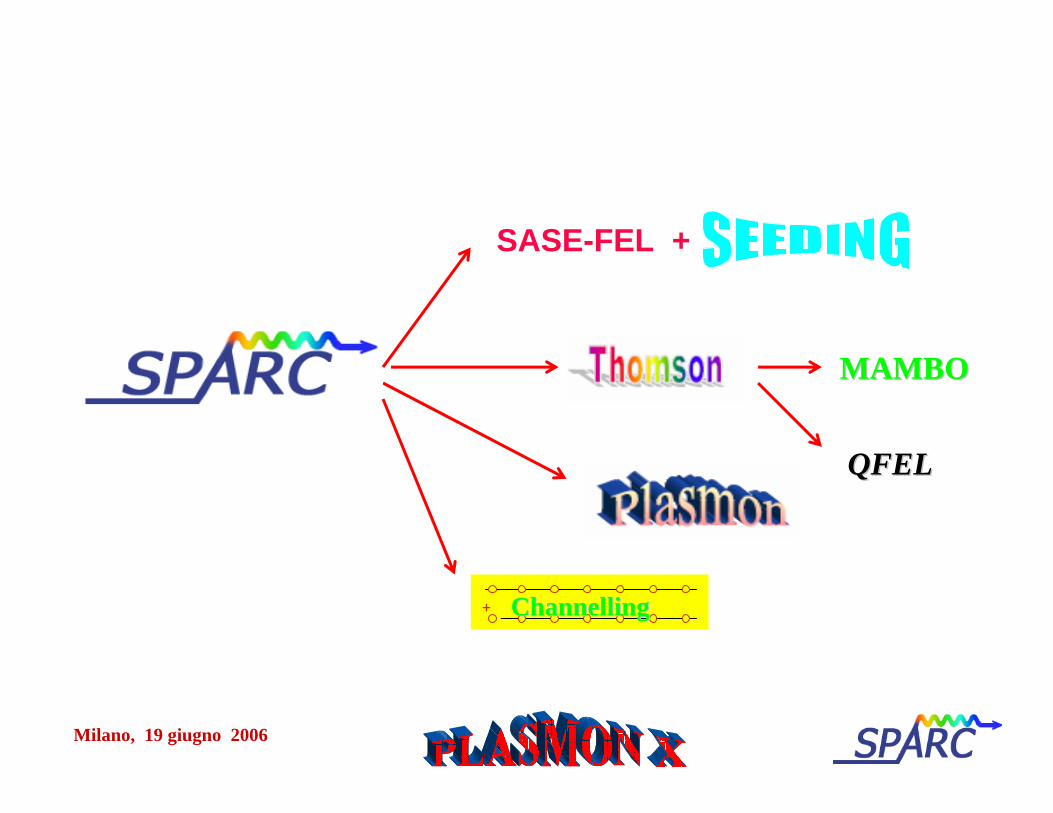
MAMBOMAMBO
+ ChannellingChannelling
SASE-FEL +
QFELQFEL
Milano, 19 giugno 2006
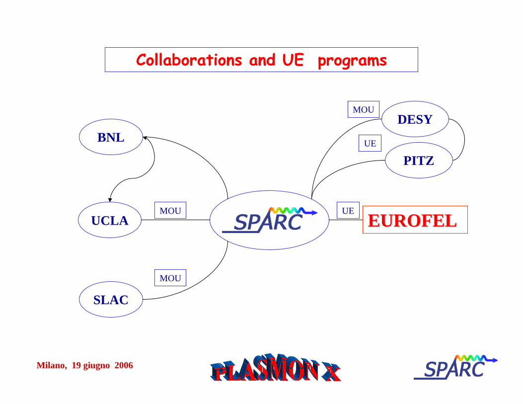
Collaborations and UE programs
SPARC
DESYBNL
UCLA
SLAC
UE
MOU
MOU
UEEUROFELEUROFEL
PITZ
MOU

Milano, 19 giugno 2006
Milano, 19 giugno 2006
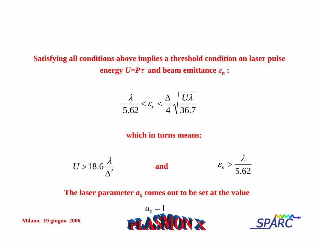
U >18.6 λΔ2
Satisfying all conditions above implies a threshold condition on laser pulse energy U=Pτ and beam emittance εn :
λ5.62
< εn <Δ4
Uλ36.7
a0 =1
which in turns means:
εn >λ
5.62and
The laser parameter a0 comes out to be set at the value
Milano, 19 giugno 2006
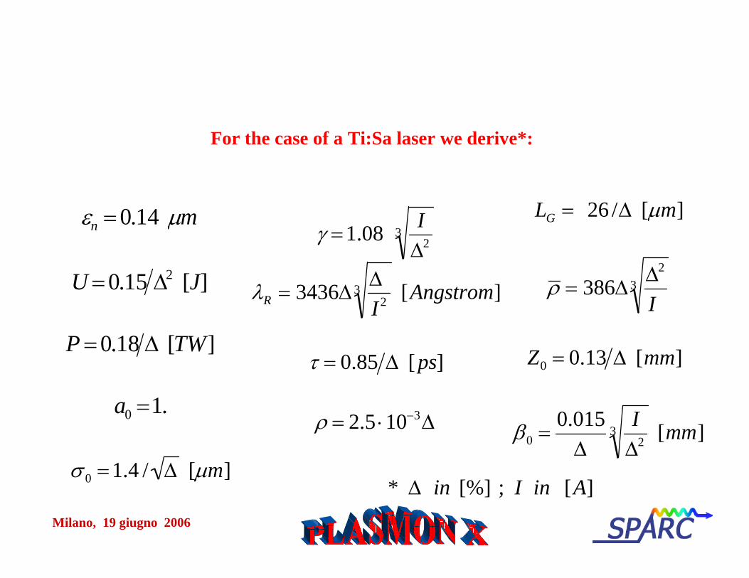
εn = 0.14 μm
U = 0.15 Δ2 [J]
P = 0.18 Δ [TW]
a0 =1.
For the case of a Ti:Sa laser we derive*:
γ =1.08 IΔ2
3
λR = 3436ΔΔI2
3 [Angstrom]
τ = 0.85 Δ [ps]
ρ = 2.5 ⋅10−3Δ
LG = 26 /Δ [μm]
ρ = 386ΔΔ2
I3
Z0 = 0.13 Δ [mm]
β0 =0.015
ΔI
Δ23 [mm]
* Δ in [%] ; I in [A]σ 0 =1.4 / Δ [μm]
Milano, 19 giugno 2006
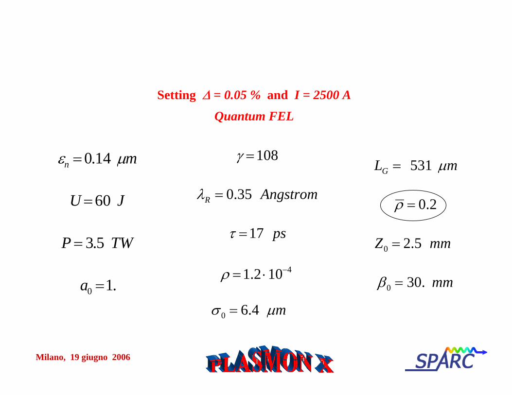
εn = 0.14 μm
U = 60 J
P = 3.5 TW
a0 =1.
Setting Δ = 0.05 % and I = 2500 A
Quantum FEL
γ =108
λR = 0.35 Angstrom
τ =17 ps
ρ =1.2 ⋅10−4
LG = 531 μm
ρ = 0.2
Z0 = 2.5 mm
β0 = 30. mm
σ 0 = 6.4 μm

Milano, 19 giugno 2006
Milano, 19 giugno 2006
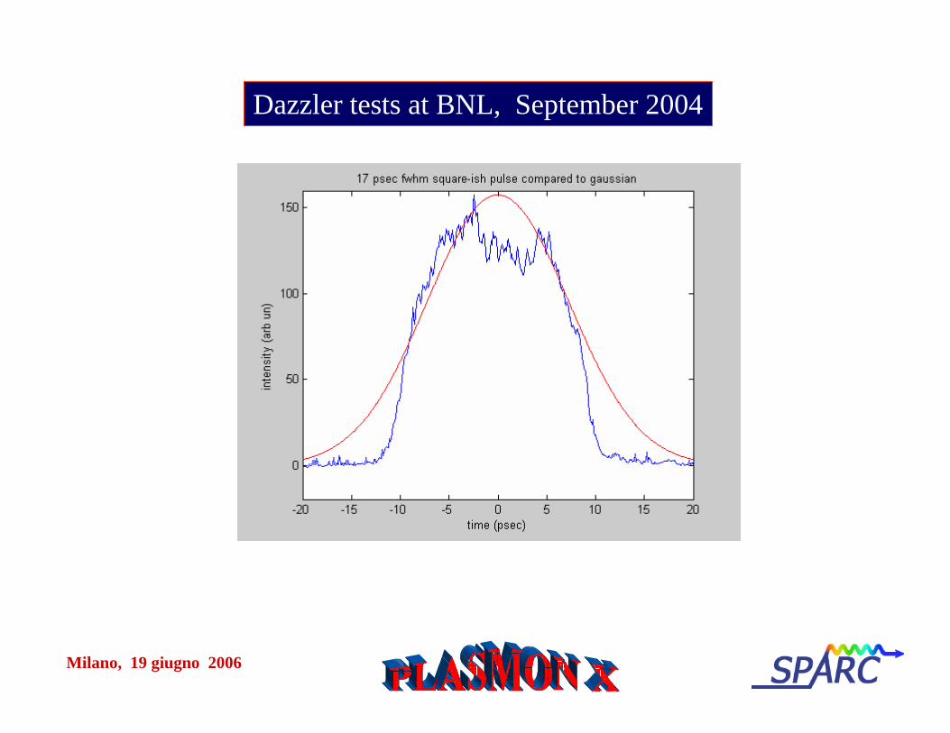
Dazzler tests at BNL, September 2004
Milano, 19 giugno 2006
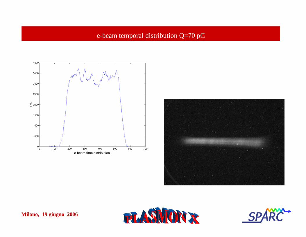
e-beam temporal distribution Q=70 pC
Milano, 19 giugno 2006
compressin aria
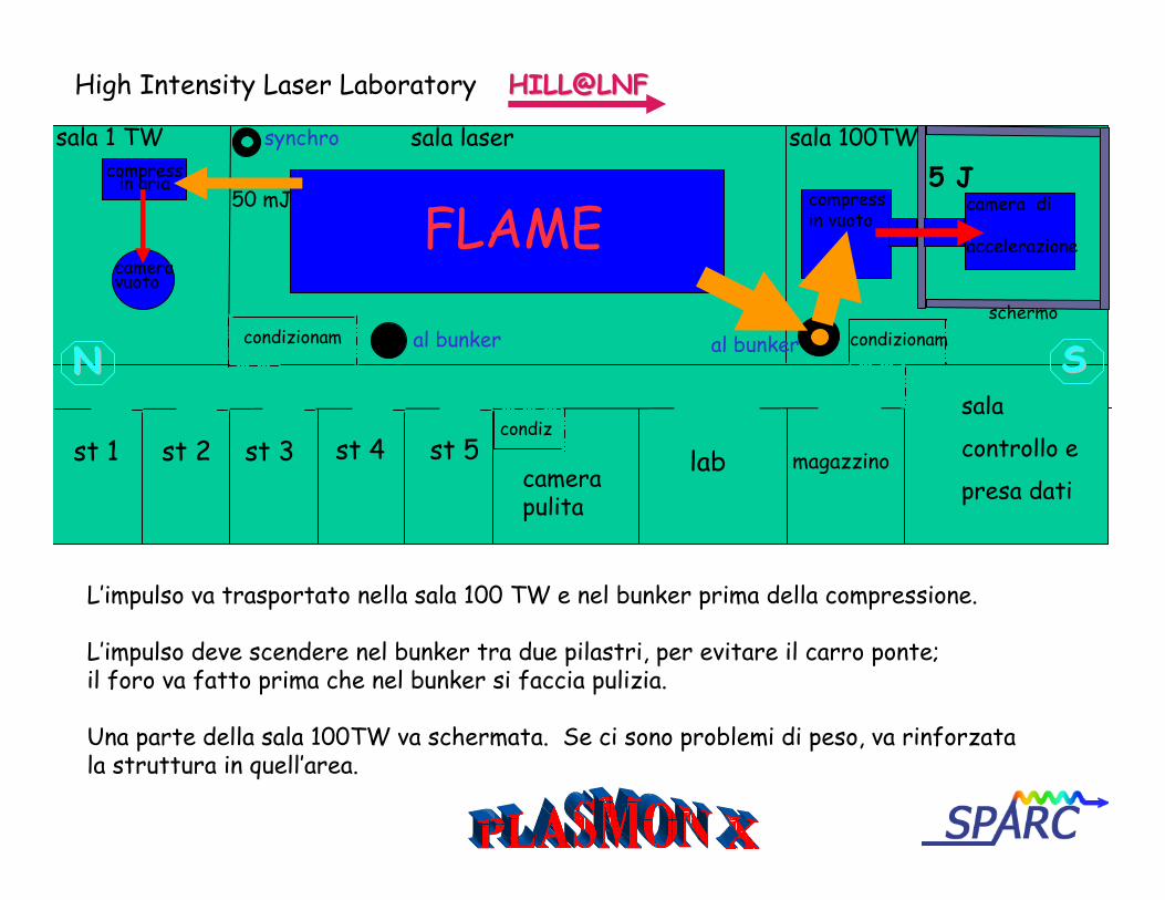
High Intensity Laser Laboratory HILL@LNFHILL@LNF
sala 1 TW sala 100TWsala laser
compressin vuoto
camera di
accelerazioneFLAME
condizionam condizionam
condizst 1 st 2 st 3 st 4 st 5
camerapulita
lab magazzino
sala
controllo e
presa dati
50 mJ 5 J
L’impulso va trasportato nella sala 100 TW e nel bunker prima della compressione.
L’impulso deve scendere nel bunker tra due pilastri, per evitare il carro ponte;il foro va fatto prima che nel bunker si faccia pulizia.
Una parte della sala 100TW va schermata. Se ci sono problemi di peso, va rinforzatala struttura in quell’area.
synchro
al bunker
cameravuoto
NN SSschermo
al bunker
Milano, 19 giugno 2006
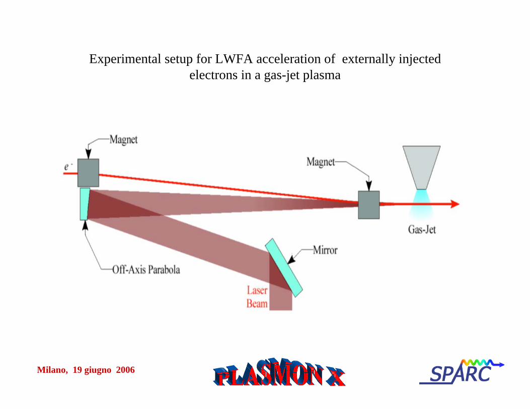
Experimental setup for LWFA acceleration of externally injectedelectrons in a gas-jet plasma

Milano, 19 giugno 2006
Milano, 19 giugno 2006
0
0.1
0.2
0.3
0.4
0.5
0.6
0 2 4 6 8 10 12 14 16
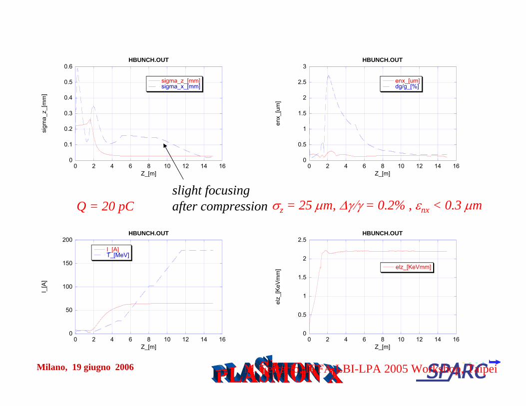
HBUNCH.OUT
sigma_z_[mm]sigma_x_[mm]
sigm
a_z_
[mm
]
Z_[m]
0
0.5
1
1.5
2
2.5
3
0 2 4 6 8 10 12 14 16
HBUNCH.OUT
enx_[um]dg/g_[%]
enx_
[um
]
Z_[m]
0
50
100
150
200
0 2 4 6 8 10 12 14 16
HBUNCH.OUT
I_[A]T_[MeV]
I_[A
]
Z_[m]
0
0.5
1
1.5
2
2.5
0 2 4 6 8 10 12 14 16
HBUNCH.OUT
elz_[KeVmm]
elz_
[KeV
mm
]
Z_[m]
slight focusingafter compression
M. Ferrario, ICFA LBI-LPA 2005 Workshop, Taipei
Q = 20 pC σz = 25 μm, Δγ/γ = 0.2% , εnx < 0.3 μm

Milano, 19 giugno 2006 C. Vaccarezza et al., EPAC-04
Bunch slicingBunch slicing
Q = 1nC ==> 25pCQ = 1nC ==> 25pC
LLbb=10 =10 ps ps ==> 100 ==> 100 fsfs
σσxx = 0.5 mm ==> 5 = 0.5 mm ==> 5 μμmm
Δγ/γ Δγ/γ < 0.2%< 0.2%
Milano, 19 giugno 2006
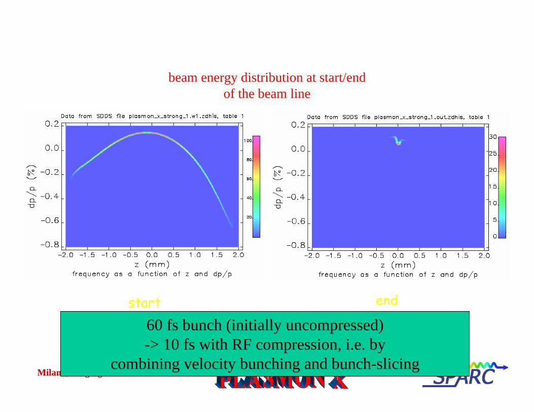
beam energy distribution at start/endof the beam line
start end
60 fs bunch (initially uncompressed)-> 10 fs with RF compression, i.e. by
combining velocity bunching and bunch-slicing