Spring 2006 Dr. Stuart Long - University of Houston
43
Chapter 11 Chapter 11 Frequency Frequency Independent Independent Antennas Antennas ECE 5318/6352 ECE 5318/6352 Antenna Engineering Antenna Engineering Spring 2006 Spring 2006 Dr. Stuart Long Dr. Stuart Long
Transcript of Spring 2006 Dr. Stuart Long - University of Houston
Chapter 11Chapter 11FrequencyFrequency
Independent Independent AntennasAntennas
ECE 5318/6352ECE 5318/6352Antenna EngineeringAntenna Engineering
Spring 2006Spring 2006Dr. Stuart LongDr. Stuart Long
2
THE BEGININGTHE BEGINING
Before 1950’s no antennas with bandwidth > 2 : 1
V.H. RumseyV.H. Rumsey – University of Illinois 1955-1958
Antenna performance is typically a function of “ length / wavelength “ λ
l
Important characteristic Important characteristic
3
SCALING PRINCIPLESCALING PRINCIPLE
Scale size by ratio of frequency and get similar behavior
e.g. decrease antenna dimensions by factor of 2 and increase frequency by factor of 2
⇒ same performance (both are the same size in wavelengths)
depends on some ““characteristic lengthcharacteristic length””
4
SCALING PRINCIPLESCALING PRINCIPLE(CONT)(CONT)
Basic structural feature for frequency independent operation is the absenceabsence of any ““characteristic lengthcharacteristic length””
⇒ self -scaling
5
ANGLE PRINCIPLEANGLE PRINCIPLE
need a structure completely described by angles
““ANGLE PRINCIPLEANGLE PRINCIPLE””
α
6
TRUNCATION PRINCIPLETRUNCATION PRINCIPLE
but practical structures need to be finite in sizesomehow currents need to fall off rapidlyenough so that terminating the structure at some finite length does not alter its characteristics
““TRUNCATION PRINCIPLETRUNCATION PRINCIPLE””
7
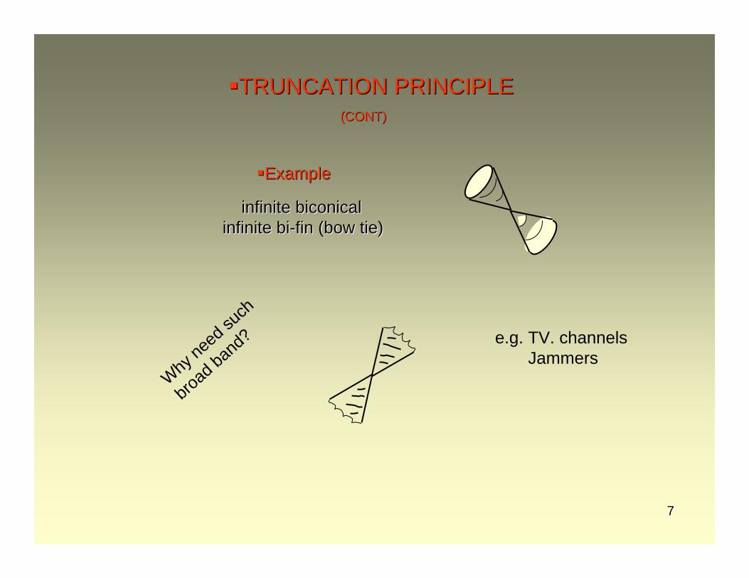
TRUNCATION PRINCIPLETRUNCATION PRINCIPLE(CONT)(CONT)
infinite biconical infinite biconical infinite biinfinite bi--fin (bow tie)fin (bow tie)
Why ne
ed su
ch
broad
band
? e.g. TV. channelsJammers
ExampleExample
8
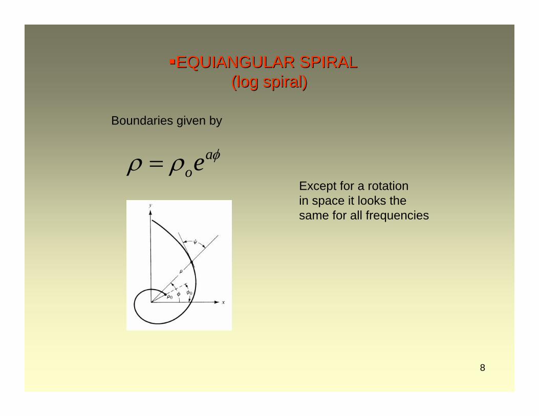
EQUIANGULAR SPIRAL EQUIANGULAR SPIRAL (log spiral) (log spiral)
Boundaries given by
aoe
φρ ρ=Except for a rotation in space it looks the same for all frequencies
9
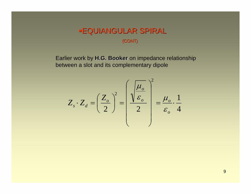
EQUIANGULAR SPIRALEQUIANGULAR SPIRAL(CONT)(CONT)
Earlier work by H.G. BookerH.G. Booker on impedance relationship between a slot and its complementary dipole
41
22
2
2
⋅=
⎟⎟⎟⎟⎟
⎠
⎞
⎜⎜⎜⎜⎜
⎝
⎛
=⎟⎠⎞
⎜⎝⎛=⋅
o
oo
o
ods
ZZZεμε
μ
10
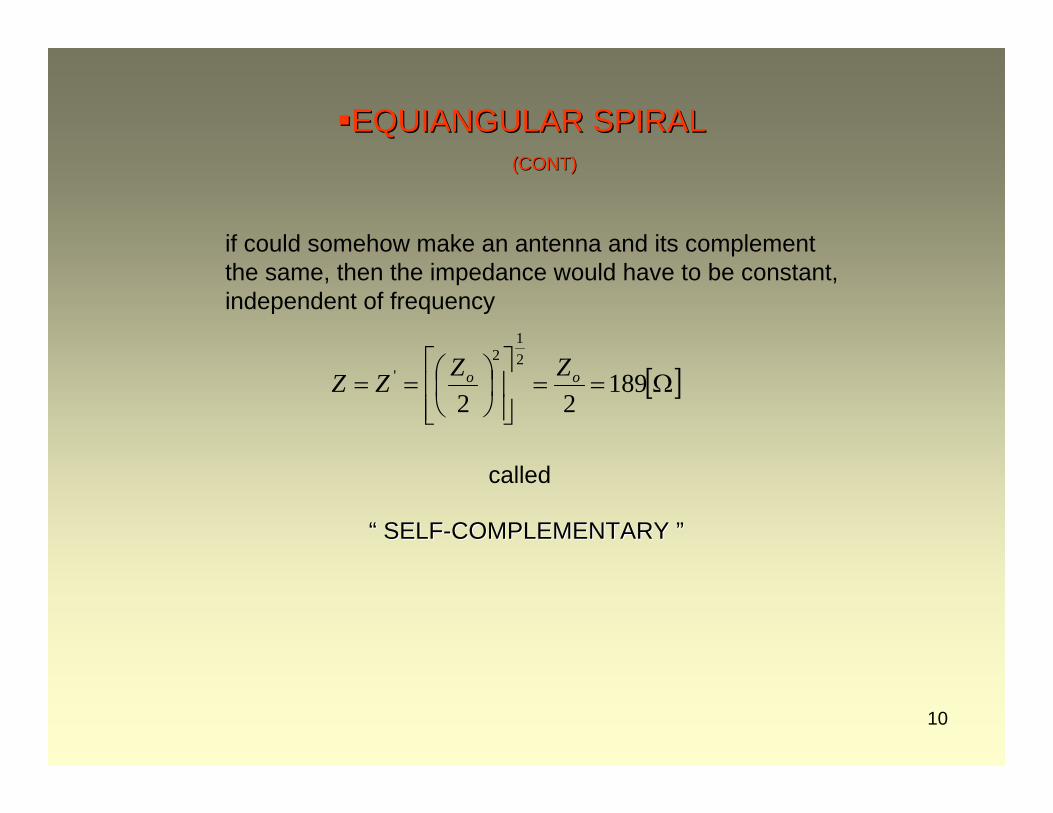
EQUIANGULAR SPIRALEQUIANGULAR SPIRAL(CONT)(CONT)
if could somehow make an antenna and its complement the same, then the impedance would have to be constant, independent of frequency
[ ]Ω==⎥⎥⎦
⎤
⎢⎢⎣
⎡⎟⎠⎞
⎜⎝⎛== 189
22
21
2' oo ZZZZ
called
““ SELFSELF--COMPLEMENTARY COMPLEMENTARY ””
11
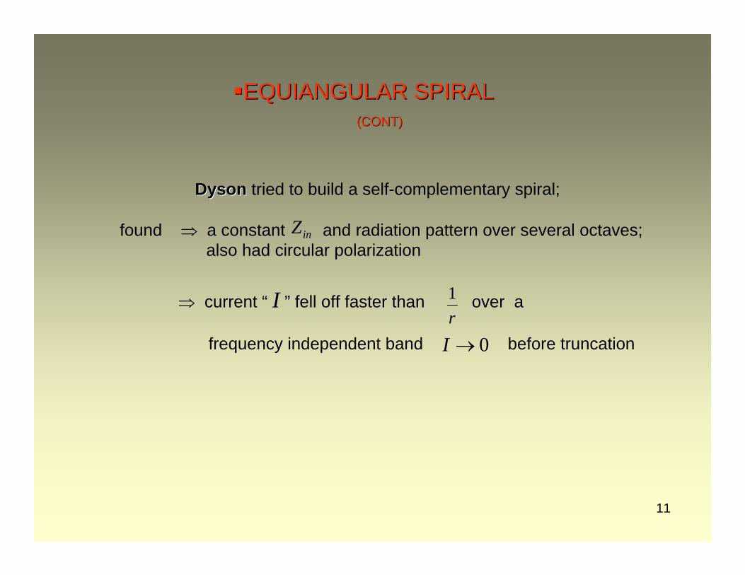
EQUIANGULAR SPIRALEQUIANGULAR SPIRAL(CONT)(CONT)
DysonDyson tried to build a self-complementary spiral;
found ⇒ a constant and radiation pattern over several octaves; also had circular polarization
0→I
⇒ current “ I ” fell off faster than over a
frequency independent band before truncationr1
inZ
12
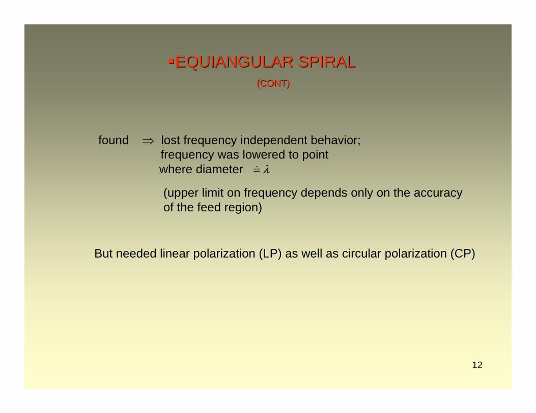
EQUIANGULAR SPIRALEQUIANGULAR SPIRAL(CONT)(CONT)
λ=
found ⇒ lost frequency independent behavior; frequency was lowered to pointwhere diameter
(upper limit on frequency depends only on the accuracy of the feed region)
But needed linear polarization (LP)LP) as well as circular polarization (CP)CP)
13
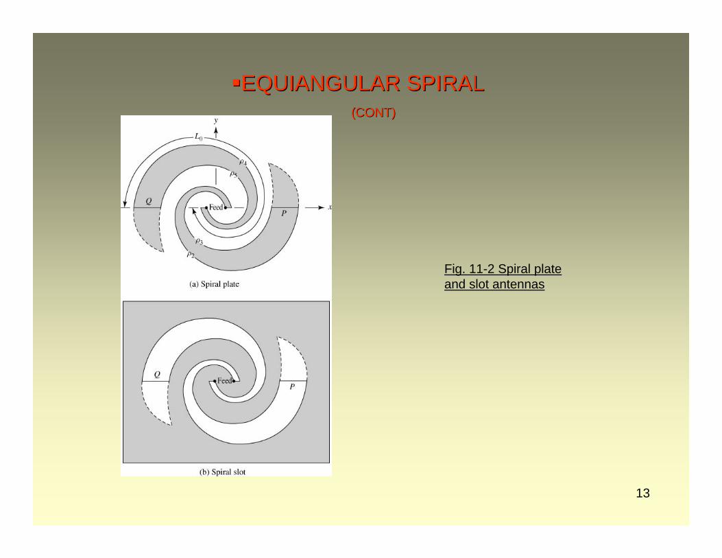
EQUIANGULAR SPIRALEQUIANGULAR SPIRAL(CONT)(CONT)
Fig. 11-2 Spiral plate and slot antennas
14
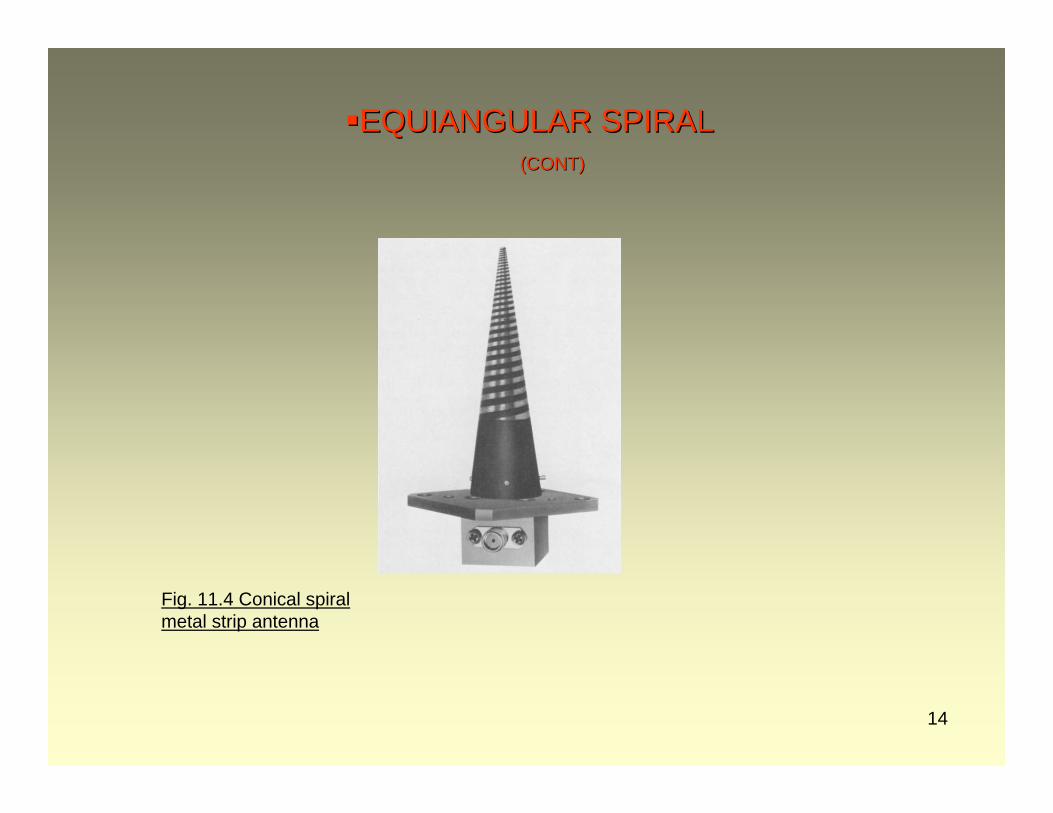
EQUIANGULAR SPIRALEQUIANGULAR SPIRAL(CONT)(CONT)
Fig. 11.4 Conical spiral metal strip antenna
15
LOG PERIODICLOG PERIODIC
DuHamelDuHamel – University of Illinois ⇒ altered the bi-fin antenna
linear polarization, satisfied ANGLE PRIN., but not TRUNCATION PRIN.
needed to cause currents to fall off more rapidly
⇒ introduced discontinuities – “teeth” in fins –to increase radiation and increase decay of “I “
16
LOG PERIODICLOG PERIODIC(CONT)(CONT)
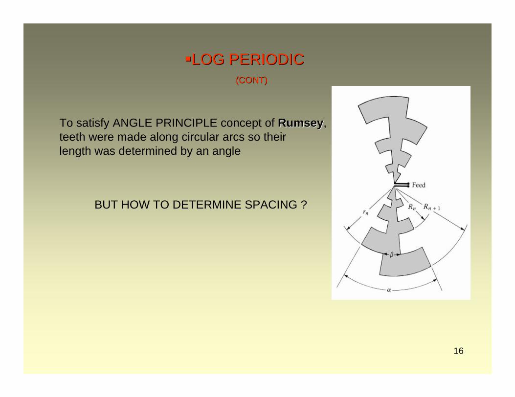
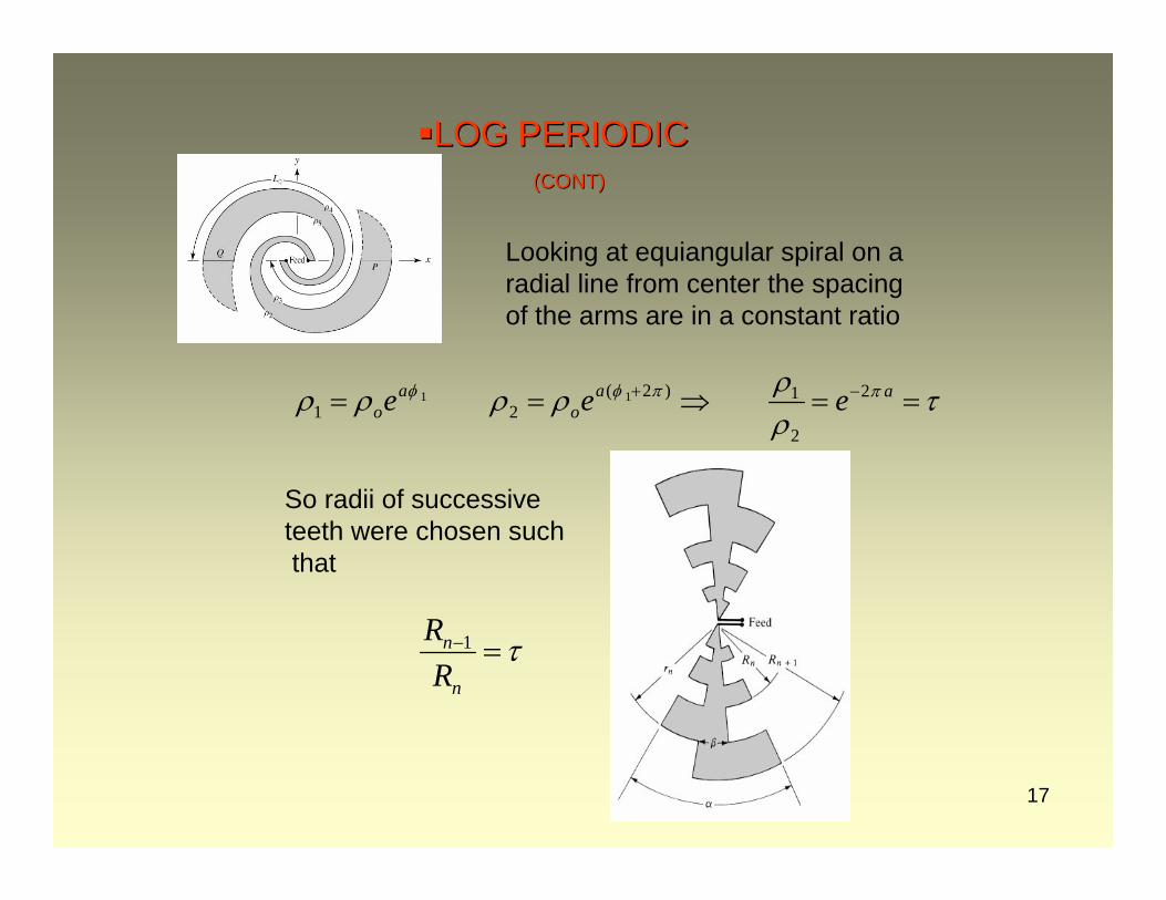
To satisfy ANGLE PRINCIPLE concept of RumseyRumsey, teeth were made along circular arcs so their length was determined by an angle
BUT HOW TO DETERMINE SPACING ?
17
LOG PERIODICLOG PERIODIC(CONT)(CONT)
Looking at equiangular spiral on a radial line from center the spacing of the arms are in a constant ratio
τρρρρρρ ππφφ ==⇒== −+ aa
oa
o eee 2
2
1)2(21
11
τ=−
n
n
RR 1
So radii of successive teeth were chosen suchthat

18
LOG PERIODICLOG PERIODIC(CONT)(CONT)
Resulting structure is not exactly frequency independent, but it should have identical characteristics at a discrete number of frequencies
ExampleExample
τof
If the p-th tooth is at then the
(p-1)th tooth is at
of10λ
10λ
19
LOG PERIODICLOG PERIODIC(CONT)(CONT)
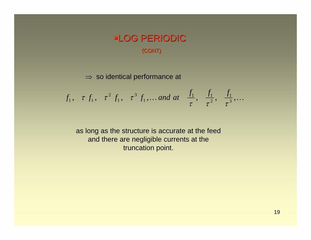
as long as the structure is accurate at the feedand there are negligible currents at the
truncation point.
…… ,,,,,,, 31
211
13
12
11 ττττττ fffatandffff
⇒ so identical performance at
20
LOG PERIODICLOG PERIODIC(CONT)(CONT)
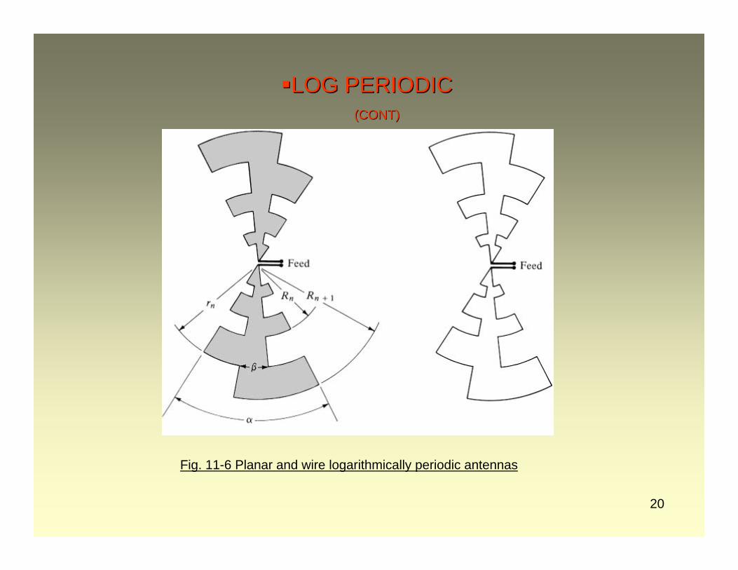
Fig. 11-6 Planar and wire logarithmically periodic antennas
21
LOG PERIODICLOG PERIODIC(CONT)(CONT)
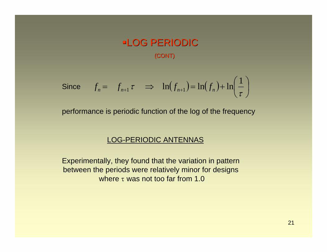
Since
performance is periodic function of the log of the frequency
( ) ( ) ⎟⎠⎞
⎜⎝⎛+=⇒= ++ τ
τ 1lnlnln 11 nnnn ffff
LOG-PERIODIC ANTENNAS
Experimentally, they found that the variation in pattern between the periods were relatively minor for designs
where τ was not too far from 1.0
22
LOG PERIODICLOG PERIODIC(CONT)(CONT)
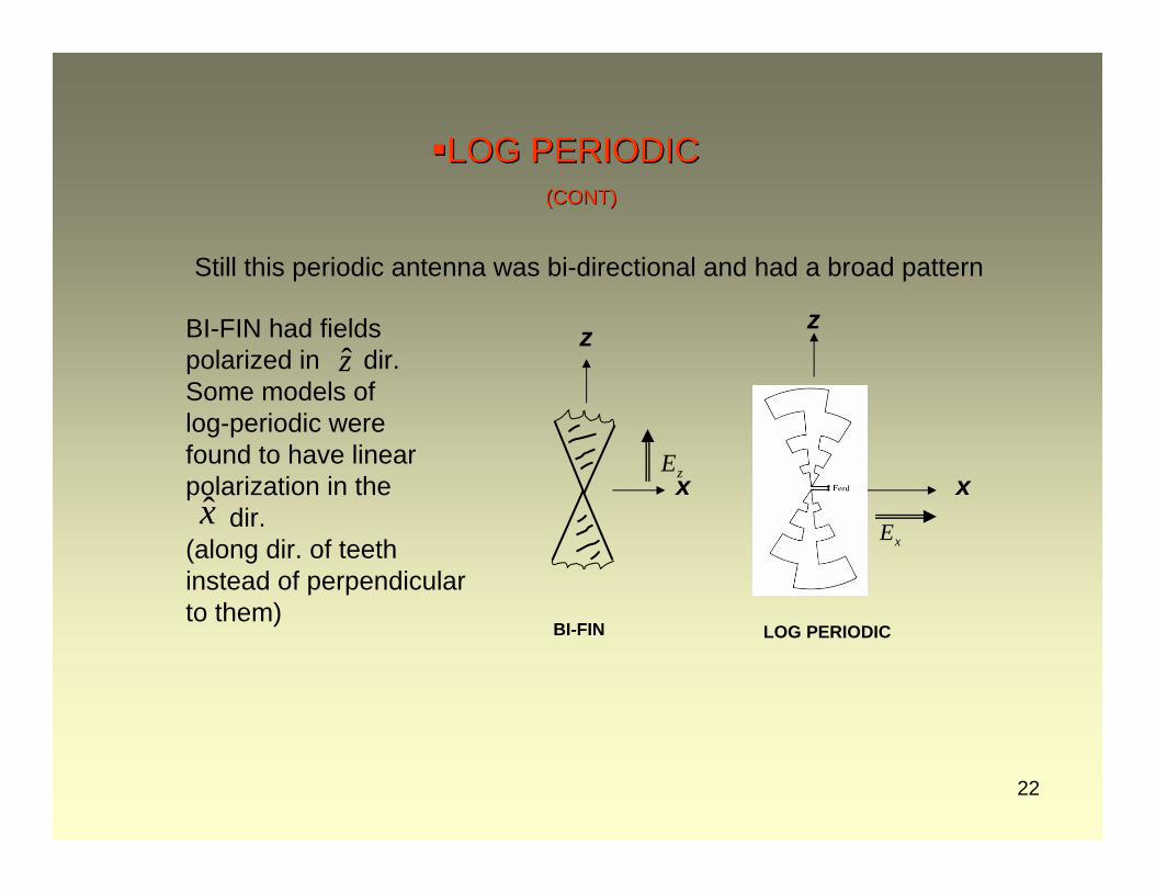
Still this periodic antenna was bi-directional and had a broad pattern
BI-FIN had fieldspolarized in dir.Some models of log-periodic were found to have linearpolarization in the
dir.(along dir. of teethinstead of perpendicularto them)
xxE
zE
BI-FIN LOG PERIODIC
z z
xx
z
23
LOG PERIODICLOG PERIODIC(CONT)(CONT)
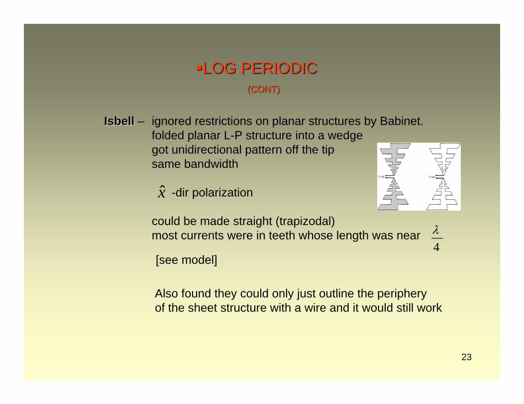
IsbellIsbell – ignored restrictions on planar structures by Babinet.folded planar L-P structure into a wedgegot unidirectional pattern off the tipsame bandwidth
-dir polarization
could be made straight (trapizodal)most currents were in teeth whose length was near
4λ
x
[see model]
Also found they could only just outline the peripheryof the sheet structure with a wire and it would still work
24
LOG PERIODICLOG PERIODIC(CONT)(CONT)
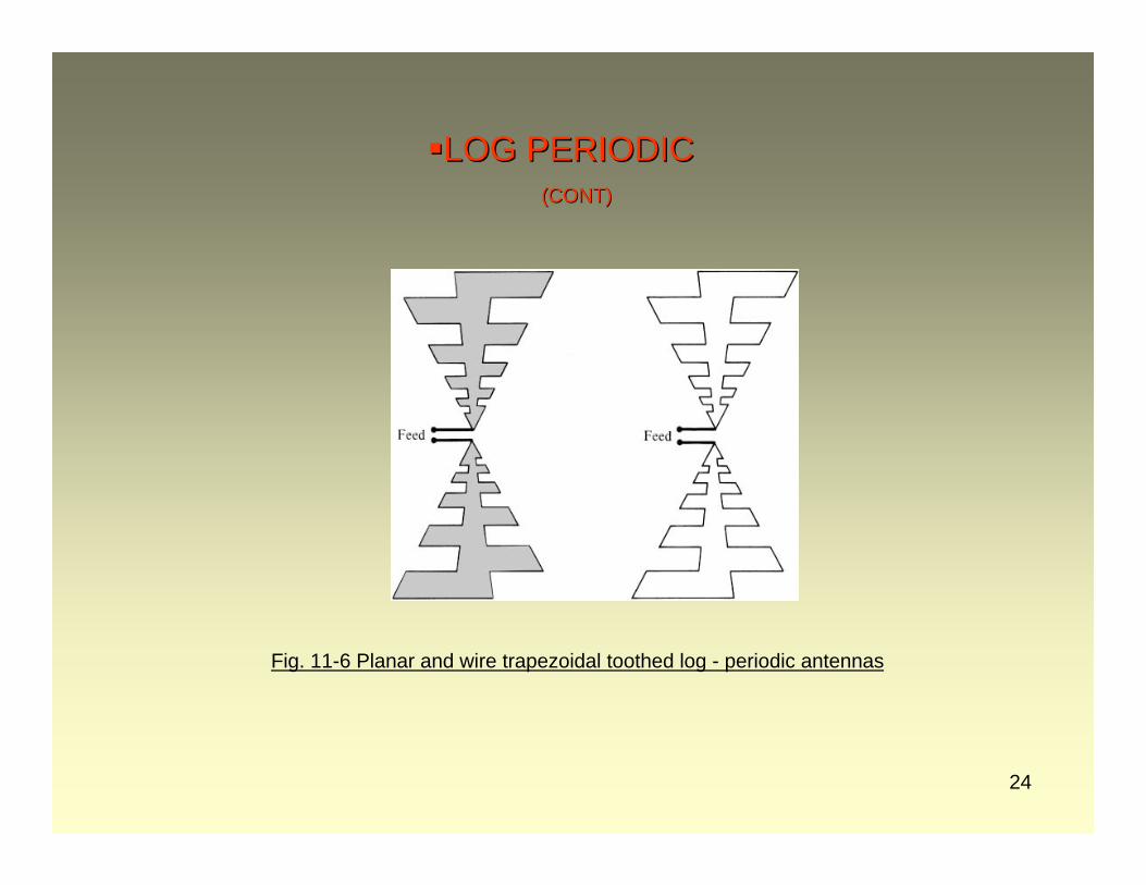
Fig. 11-6 Planar and wire trapezoidal toothed log - periodic antennas
25
LOGLOG--PERIODICPERIODIC(CONT)(CONT)
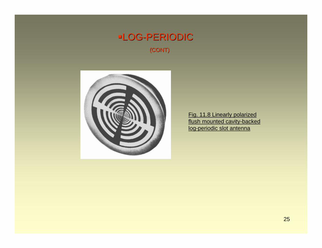
Fig. 11.8 Linearly polarizedflush mounted cavity-backedlog-periodic slot antenna
26
LOG PERIODICLOG PERIODIC(CONT)(CONT)
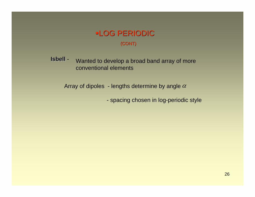
Isbell Isbell -
α
Wanted to develop a broad band array of more conventional elements
Array of dipoles - lengths determine by angle
- spacing chosen in log-periodic style
27
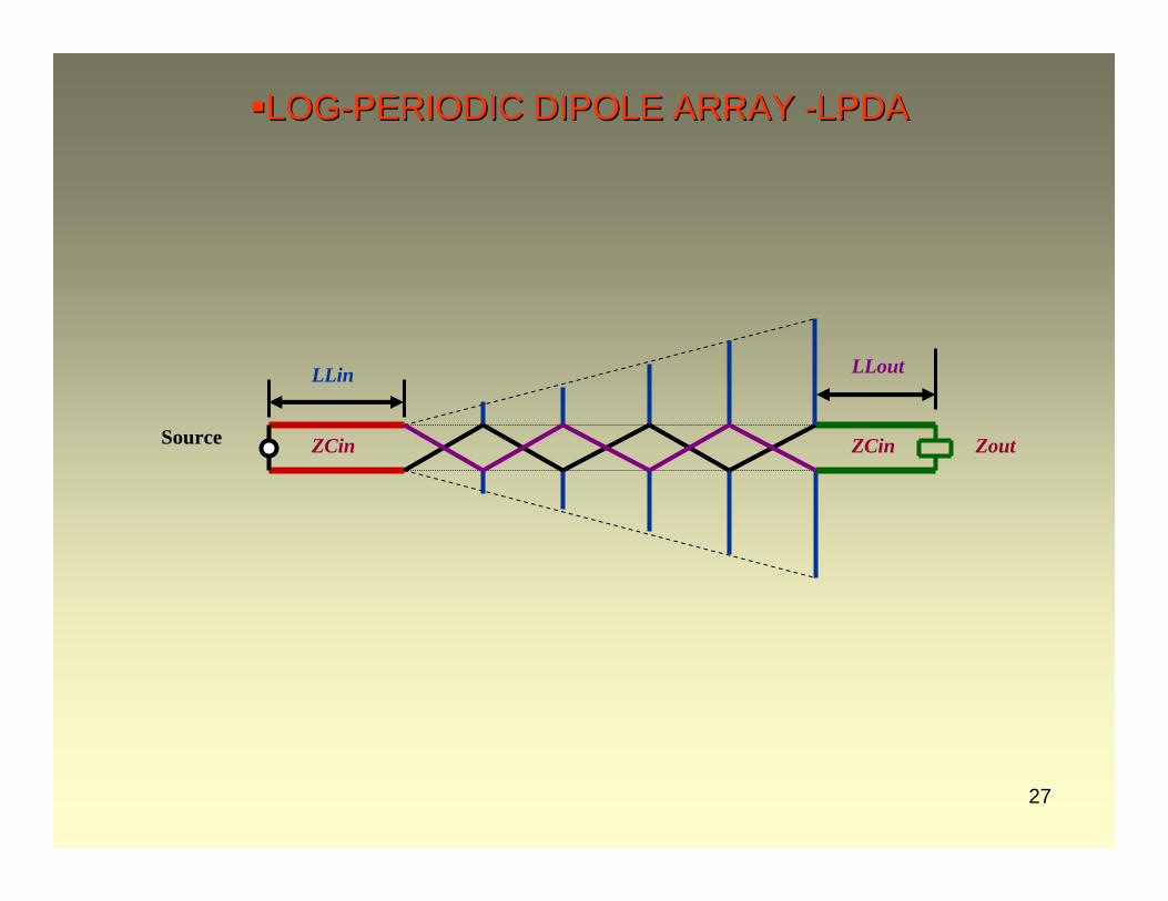
ZoutZCin
LLin LLout
ZCinSource
LOGLOG--PERIODIC DIPOLE ARRAY PERIODIC DIPOLE ARRAY --LPDALPDA
28
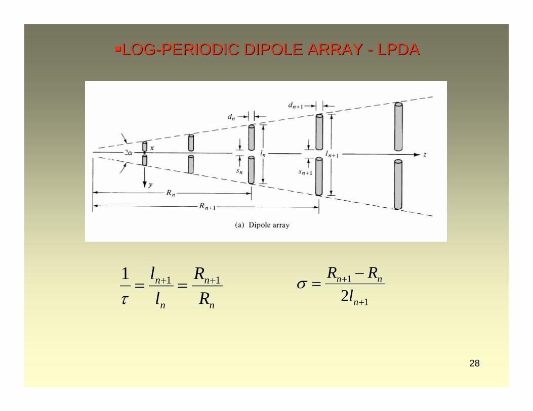
LOGLOG--PERIODIC DIPOLE ARRAY PERIODIC DIPOLE ARRAY -- LPDALPDA
n
n
n
n
RR
ll 111 ++ ==
τ 1
1
2 +
+ −=
n
nn
lRRσ
29
LPDALPDA(CONT)(CONT)
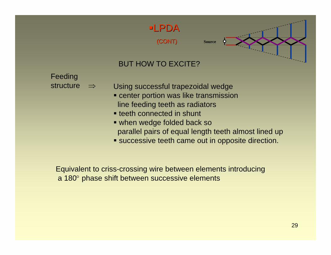
BUT HOW TO EXCITE?
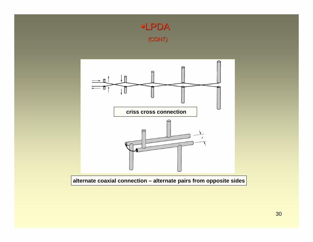
Using successful trapezoidal wedgecenter portion was like transmission line feeding teeth as radiatorsteeth connected in shuntwhen wedge folded back soparallel pairs of equal length teeth almost lined upsuccessive teeth came out in opposite direction.
Equivalent to criss-crossing wire between elements introducinga 180° phase shift between successive elements
Feeding structure ⇒
Source
30
LPDALPDA(CONT)(CONT)
criss cross connection
alternate coaxial connection – alternate pairs from opposite sides
31
LPDALPDA(CONT)(CONT)
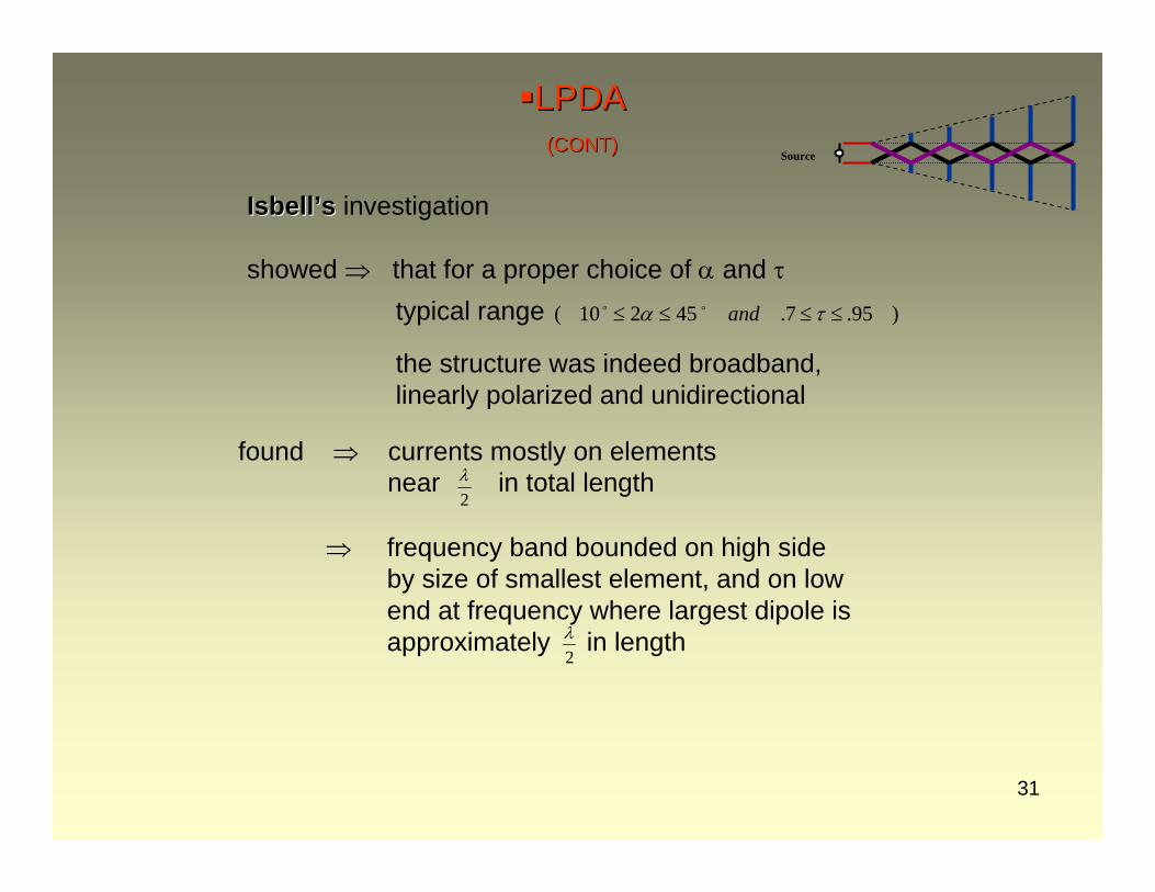
IsbellIsbell’’ss investigation
showed ⇒ that for a proper choice of α and τtypical range )95.7.45210( ≤≤≤≤ τα and
2λ
the structure was indeed broadband, linearly polarized and unidirectional
found ⇒ currents mostly on elementsnear in total length
frequency band bounded on high sideby size of smallest element, and on lowend at frequency where largest dipole is approximately in length
⇒
2λ
Source
32
LPDALPDA(CONT)(CONT)
⎟⎟⎠
⎞⎜⎜⎝
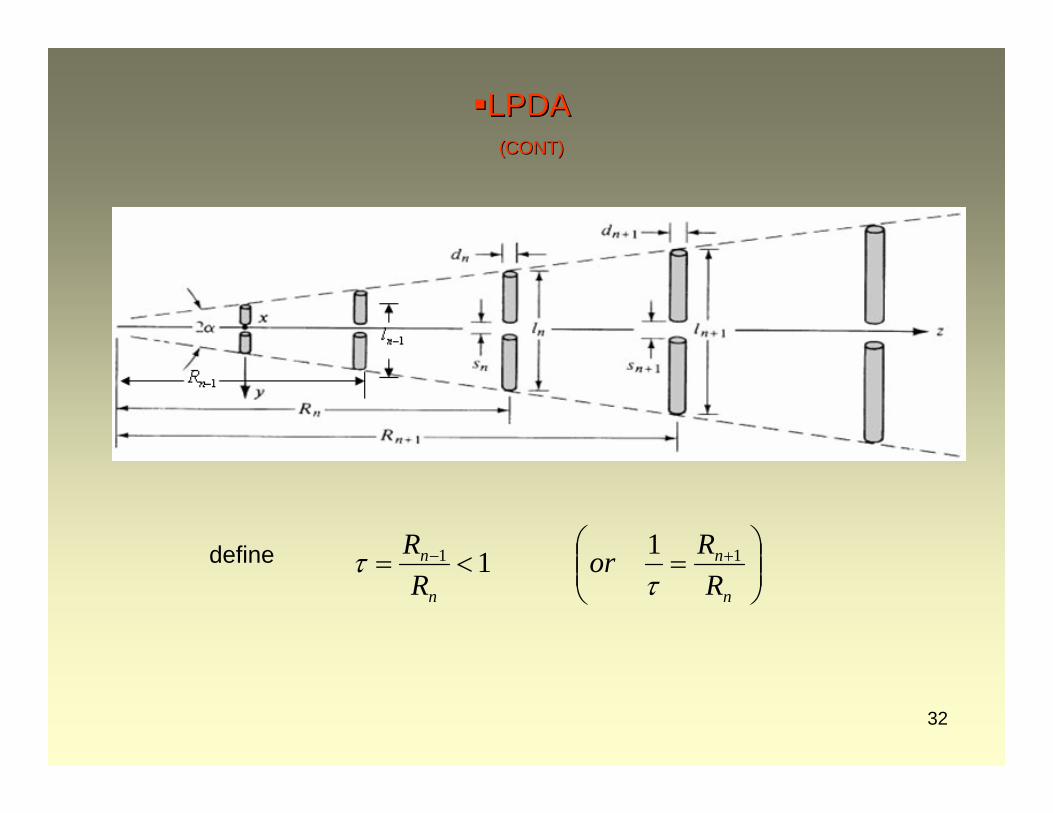
⎛=<= +−
n
n
n
n
RRor
RR 11 11
ττdefine
33
LPDALPDA(CONT)(CONT)
n
n
n
n
n
n
n
n
n
n
ll
RR
Rl
Rl
Rl 11
1
1
1
1 −−
−
−
+
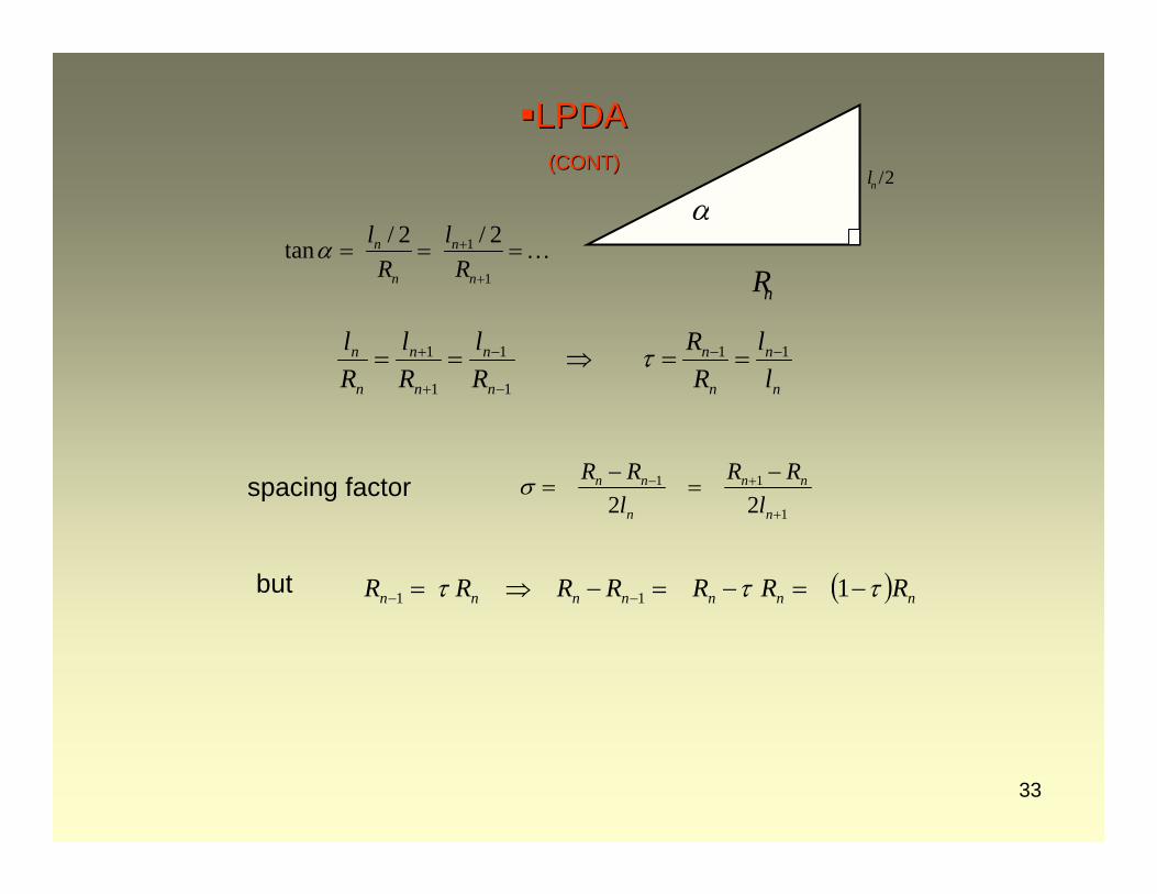
+ ==⇒== τ
1
1
/ 2 / 2tan n n
n n
l lR R
α +
+
= = =…
/2nl
nR
α
( ) nnnnnnn RRRRRRR τττ −=−=−⇒= −− 111
1
11
22 +
+− −=
−=
n
nn
n
nn
lRR
lRRσspacing factor
but
34
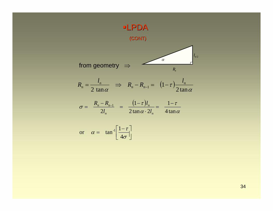
LPDALPDA(CONT)(CONT)
( )α
τα tan2
1tan2 1
nnn
nn
lRRlR −=−⇒= −
⎥⎦⎤
⎢⎣⎡ −
=στα
41tanor 1-
from geometry ⇒
( )ατ
ατσ
tan41
2tan21
21 −
=⋅
−=
−= −
n
n
n
nn
ll
lRR
2/nl
nR
α
35
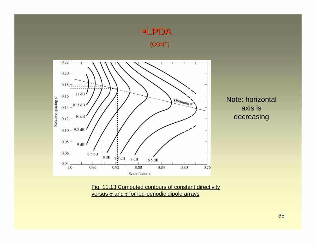
LPDALPDA(CONT)(CONT)
Fig. 11.13 Computed contours of constant directivity versus σ and τ for log-periodic dipole arrays
Note: horizontal axis is
decreasing
36
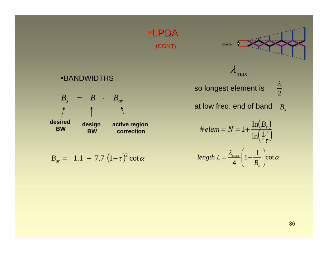
LPDALPDA(CONT)(CONT)
BANDWIDTHS
( )( )τ1ln
ln1# sBNelem +==
maxλ
2λ
sB
( ) ατ cot17.71.1 2−+=arB
ars BBB ⋅=
αλ cot114max
⎟⎟⎠
⎞⎜⎜⎝
⎛−=
sBLlength
design BW
active region correction
desired BW
so longest element is
at low freq. end of band
Source
37
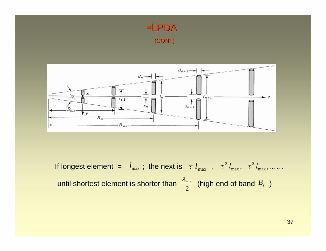
LPDALPDA(CONT)(CONT)
If longest element = ; the next is , , ,……maxl maxlτ max2 lτ max
3 lτ
2minλ
sBuntil shortest element is shorter than (high end of band )
38
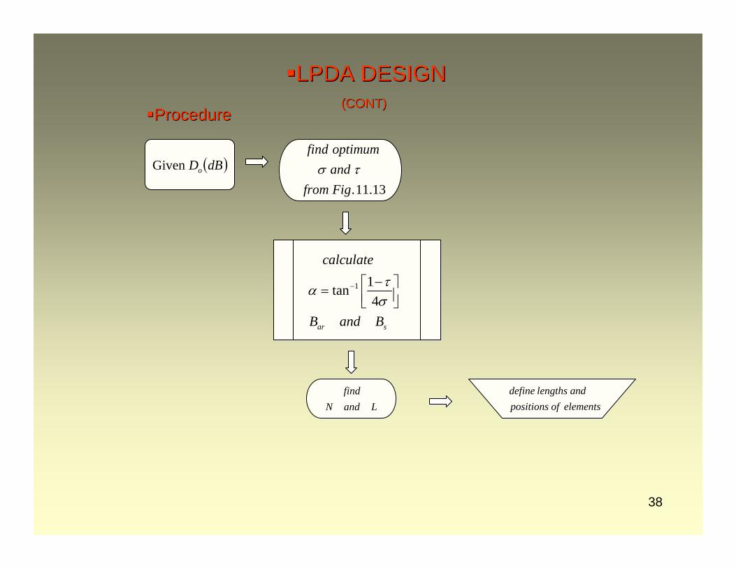
1 1tan4
ar s
calculate
B and B
τασ
− −⎡ ⎤= ⎢ ⎥⎣ ⎦
ProcedureProcedure
LandNfind define lengths and
positions of elements
( )dBDoGiven
.11.13
find optimumand
from Figσ τ
LPDA DESIGNLPDA DESIGN(CONT)(CONT)
39
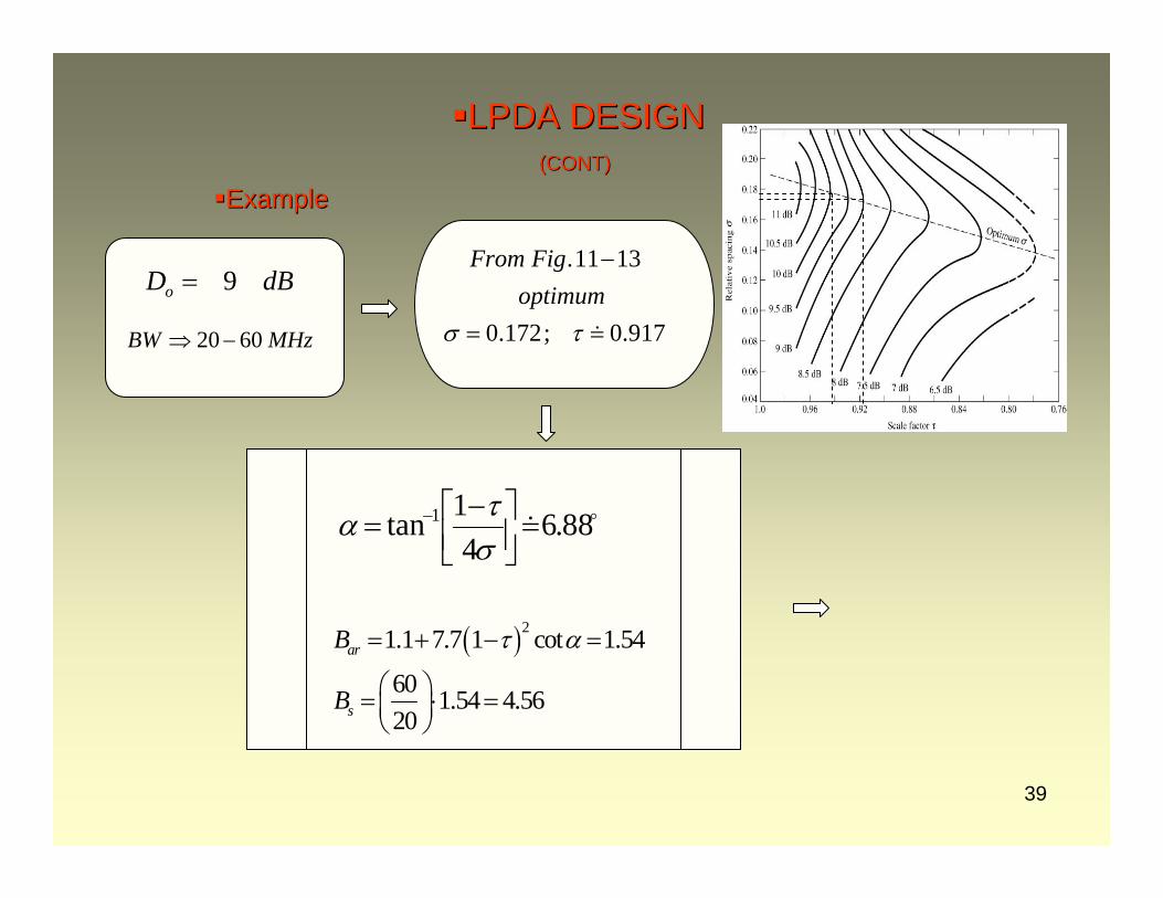
ExampleExample
917.0;172.0
1311.
==
−
τσoptimumFigFrom
MHzBW 6020−⇒
dBDo 9=
88.64
1tan 1 =⎥⎦⎤
⎢⎣⎡ −
= −
στα
( )21.1 7.7 1 cot 1.54
60 1.54 4.5620
ar
s
B
B
τ α= + − =
⎛ ⎞= ⋅ =⎜ ⎟⎝ ⎠
LPDA DESIGNLPDA DESIGN(CONT)(CONT)
40
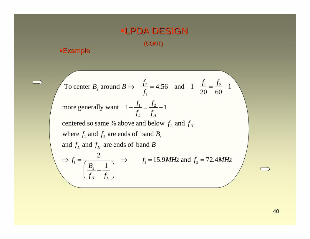
ExampleExample
2 1 2
1
1 2
1 2
1 1 2
To center around 4.56 and 1 120 60
more generally want 1 1
centered so same % above and below andwhere and are ends of bandand and are ends of band
2 15.9 and 72.41
s
L H
L H
s
L H
s
H L
f f fB Bf
f ff f
f ff f B
f f B
f f MHz f MBf f
⇒ = − = −
− = −
⇒ = ⇒ = =⎛ ⎞
+⎜ ⎟⎝ ⎠
Hz
LPDA DESIGNLPDA DESIGN(CONT)(CONT)
41
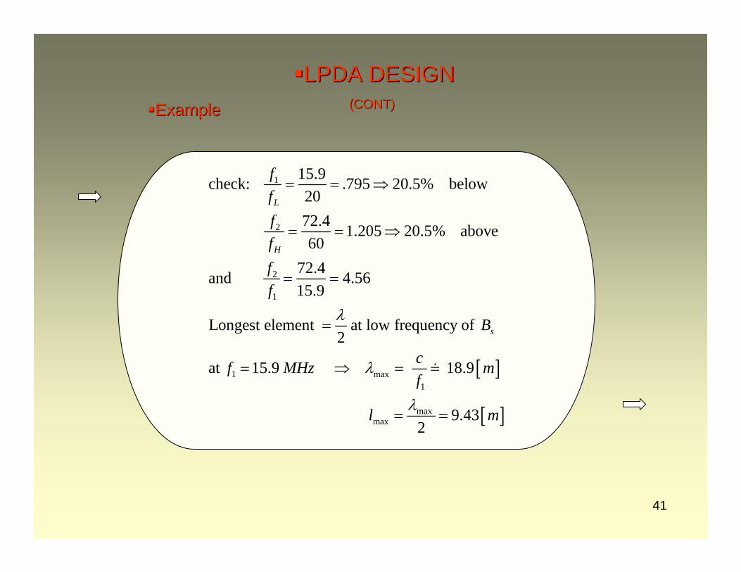
ExampleExample
[ ]
[ ]
1
2
2
1
1 max1
maxmax
15.9check: .795 20.5% below2072.4 1.205 20.5% above60
72.4and 4.5615.9
Longest element at low frequency of2
at 15.9 18.9
9.432
L
H
s
ffffff
B
cf MHz mf
l m
λ
λ
λ
= = ⇒
= = ⇒
= =
=
= ⇒ = =
= =
LPDA DESIGNLPDA DESIGN(CONT)(CONT)
42
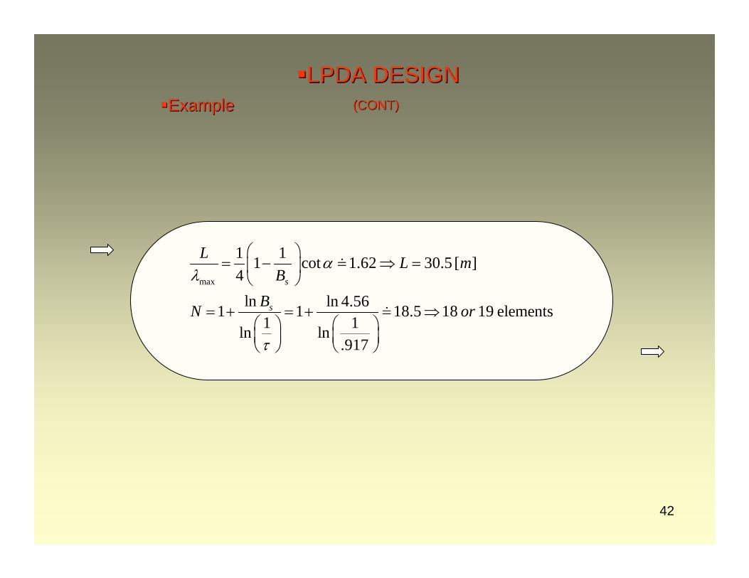
ExampleExample
max
1 11 cot 1.62 30.5 [ ]4
ln ln 4.561 1 18.5 18 19 elements1 1ln ln
.917
s
s
L L mB
BN or
αλ
τ
⎛ ⎞= − = ⇒ =⎜ ⎟
⎝ ⎠
= + = + = ⇒⎛ ⎞ ⎛ ⎞⎜ ⎟ ⎜ ⎟⎝ ⎠ ⎝ ⎠
LPDA DESIGNLPDA DESIGN(CONT)(CONT)
43
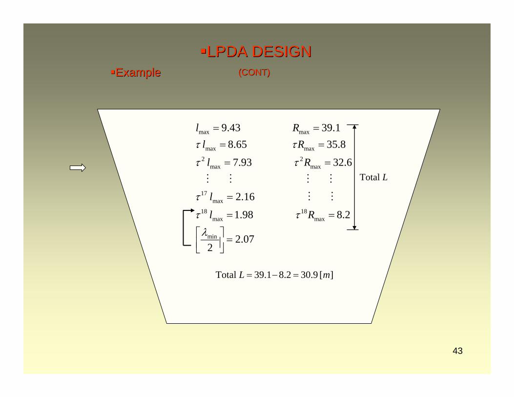
ExampleExample
LTotal
max max
max max
2 2max max
17max
18 18max max
min
9.43 39.18.65 35.8
7.93 32.6
2.16
1.98 8.2
2.072
l Rl R
l R
l
l R
τ τ
τ τ
τ
τ τλ
= == =
= =
=
= =
⎡ ⎤ =⎢ ⎥⎣ ⎦
][9.302.81.39Total mL =−=
LPDA DESIGNLPDA DESIGN(CONT)(CONT)