Split-type Air-Conditioner · Split-type Air-Conditioner MXZ-6D122VA MXZ-4E83VAHZ Türkçe Svenska...
9
Split-type Air-Conditioner MXZ-6D122VA MXZ-4E83VAHZ Türkçe Svenska Dansk Português Ελληνικά Italiano Español Nederlands Français Deutsch English Installation Manual For INSTALLER • This manual only describes the installation of outdoor unit. When installing the indoor unit, refer to the installation manual of indoor unit. Installationsanleitung Für INSTALLATEUR • Diese Installationsanleitung gilt nur für die Installation des Außengerätes. Zur Installation des Innengeräts siehe die Installationsanleitung für Innengeräte. Notice d’installation Destinée à l’INSTALLATEUR • Cette notice ne décrit que l’installation de l’appareil extérieur. Lors de l’installation de l’appareil intérieur, consultez la notice d’installation de cet appareil. Installatiehandleiding Voor de INSTALLATEUR • Deze handleiding beschrijft alleen de installatie van de buitenunit. Raadpleeg de installatiehandleiding van de binnenunit wanneer u deze instal- leert. Manual de instalación Para el INSTALADOR • En este manual sólo se describe la instalación de la unidad exterior. Para instalar la unidad interior, consulte el manual de instalación de dicha uni- dad. Manuale per l’installazione Per il TECNICO INSTALLATORE • Questo manuale descrive solo l’installazione dell’unità esterna. Per l’installazione dell’unità interna, fare riferimento al relativo manuale di instal- lazione. Εγχειρίδιο εγκατάστασης Για τον ΤΕΧΝΙΚΟ • Στο παρόν εγχειρίδιο περιγράφεται μόνο η εγκατάσταση της μονάδας εξωτερικού χώρου. Για την εγκατάσταση της μονάδας εσωτερικού χώρου, ανατρέξτε στο εγχειρίδιο εγκατάστασης της μονάδας εσωτερικού χώρου. Manual de Instalação Para o INSTALADOR • Este manual descreve apenas a instalação da unidade exterior. Quando proceder à instalação da unidade interior, consulte o manual de instalação da unidade interior. Installationshåndbog Til INSTALLATØREN • Denne håndbog beskriver kun, hvordan udendørsenheden installeres. Vedrørende installation af indendørsenheden henvises til installationshåndbogen for indendørsenheden. Installationsanvisning För INSTALLATÖREN • Denna installationsanvisning beskriver endast installation av utomhusenheten. Se den separata installationsanvisningen för inomhusenheten. Kurulum Kılavuzu TESİSATÇI İÇİN • Bu kılavuzda yalnızca dış ünitenin kurulumu açıklanmaktadır. İç ünite kurulum işlemini yaparken iç ünite kurulum kılavuzuna bakın. English is original. Übersetzung des Originals Traduction du texte d’origine Vertaling van het origineel Traducción del original Traduzione dell’originale Μετάφραση του αρχικού Tradução do original Oversættelse af den originale tekst Översättning från originalet Orijinalin çevirisi Ръководство за монтаж За ИНСТАЛАТОРА • Това ръководство описва само монтажа на външното тяло. При монтиране на вътрешното тяло вижте ръководството за монтаж на вътрешното тяло. Версията на английски език е оригинал. Български
Transcript of Split-type Air-Conditioner · Split-type Air-Conditioner MXZ-6D122VA MXZ-4E83VAHZ Türkçe Svenska...
Split-type Air-ConditionerMXZ-6D122VAMXZ-4E83VAHZ
Türkçe
Svenska
Dansk
Português
Ελληνικά
Italiano
Español
Nederlands
Français
Deutsch
EnglishInstallation Manual For INSTALLER• This manual only describes the installation of outdoor unit. When installing the indoor unit, refer to the installation manual of indoor unit.
Installationsanleitung Für INSTALLATEUR• Diese Installationsanleitung gilt nur für die Installation des Außengerätes. Zur Installation des Innengeräts siehe die Installationsanleitung für Innengeräte.
Notice d’installation Destinée à l’INSTALLATEUR• Cette notice ne décrit que l’installation de l’appareil extérieur. Lors de l’installation de l’appareil intérieur, consultez la notice d’installation de cet
appareil.
Installatiehandleiding Voor de INSTALLATEUR• Deze handleiding beschrijft alleen de installatie van de buitenunit. Raadpleeg de installatiehandleiding van de binnenunit wanneer u deze instal-
leert.
Manual de instalación Para el INSTALADOR• En este manual sólo se describe la instalación de la unidad exterior. Para instalar la unidad interior, consulte el manual de instalación de dicha uni-
dad.
Manuale per l’installazione Per il TECNICO INSTALLATORE• Questo manuale descrive solo l’installazione dell’unità esterna. Per l’installazione dell’unità interna, fare riferimento al relativo manuale di instal-
lazione.
Εγχειρίδιο εγκατάστασης ΓιατονΤΕΧΝΙΚΟ• Στοπαρόνεγχειρίδιοπεριγράφεταιμόνοηεγκατάστασητηςμονάδαςεξωτερικούχώρου. Για την εγκατάσταση τηςμονάδας εσωτερικούχώρου,ανατρέξτεστο εγχειρίδιοεγκατάστασηςτηςμονάδαςεσωτερικούχώρου.
Manual de Instalação Para o INSTALADOR• Este manual descreve apenas a instalação da unidade exterior. Quando proceder à instalação da unidade interior, consulte o manual de instalação
da unidade interior.
Installationshåndbog Til INSTALLATØREN• Denne håndbog beskriver kun, hvordan udendørsenheden installeres. Vedrørende installation af indendørsenheden henvises til installationshåndbogen
for indendørsenheden.
Installationsanvisning För INSTALLATÖREN• Denna installationsanvisning beskriver endast installation av utomhusenheten.
Se den separata installationsanvisningen för inomhusenheten.
Kurulum Kılavuzu TESİSATÇIİÇİN• Bukılavuzdayalnızcadışüniteninkurulumuaçıklanmaktadır. İçünitekurulumişleminiyaparkeniçünitekurulumkılavuzunabakın.
English is original.
Übersetzung des Originals
Traduction du texte d’origine
Vertaling van het origineel
Traducción del original
Traduzione dell’originale
Μετάφρασητουαρχικού
Tradução do original
Oversættelse af den originale tekst
Översättning från originalet
Orijinalin çevirisi
Ръководство за монтаж ЗаИНСТАЛАТОРА• Товаръководствоописвасамомонтажанавъншнототяло. Примонтиране на вътрешното тяло вижте ръководството замонтаж навътрешнототяло.
Версиятанаанглийскиезикеоригинал. Български
BH79A198H01_en.indd 1 6/2/2015 5:48:27 PM
En-1
1-1. THE FOLLOWING SHOULD ALWAYS BE OBSERVED FOR SAFETY• Besuretoread“THEFOLLOWINGSHOULDALWAYSBEOBSERVEDFORSAFETY”beforeinstallingtheairconditioner.• Besuretoobservethewarningsandcautionsspecifiedhereastheyincludeimportantitemsrelatedtosafety.• Afterreadingthismanual,besuretokeepittogetherwiththeOPERATINGINSTRUCTIONSforfuturereference.• EquipmentcomplyingwithIEC/EN61000-3-12.
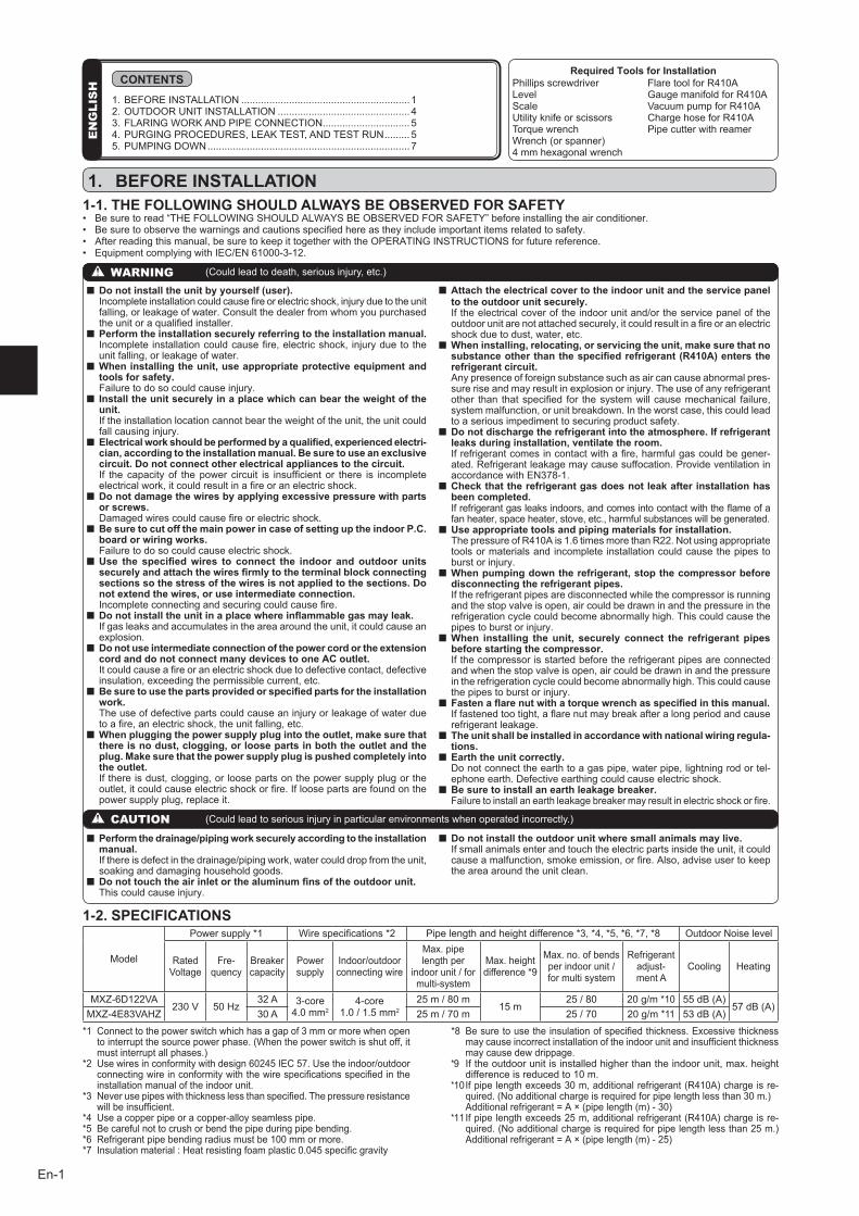
1-2. SPECIFICATIONS
Model
Power supply *1 Wirespecifications*2 Pipe length and height difference *3,*4,*5,*6,*7,*8 Outdoor Noise level
Rated Voltage
Fre-quency
Breaker capacity
Power supply
Indoor/outdoorconnecting wire
Max. pipe length per
indoorunit/formulti-system
Max. height difference *9
Max. no. of bends perindoorunit/for multi system
Refrigerant adjust-ment A
Cooling Heating
MXZ-6D122VA230V 50Hz
32A 3-core 4.0mm2
4-core 1.0/1.5mm2
25m/80m15m
25/80 20g/m*10 55dB(A)57dB(A)
MXZ-4E83VAHZ 30A 25m/70m 25/70 20g/m*11 53dB(A)
*1 Connecttothepowerswitchwhichhasagapof3mmormorewhenopentointerruptthesourcepowerphase.(Whenthepowerswitchisshutoff,itmustinterruptallphases.)
*2 Usewiresinconformitywithdesign60245IEC57.Usetheindoor/outdoorconnectingwireinconformitywiththewirespecificationsspecifiedintheinstallation manual of the indoor unit.
*3 Neverusepipeswiththicknesslessthanspecified.Thepressureresistancewillbeinsufficient.
*4 Useacopperpipeoracopper-alloyseamlesspipe.*5 Becarefulnottocrushorbendthepipeduringpipebending.*6 Refrigerantpipebendingradiusmustbe100mmormore.*7 Insulationmaterial:Heatresistingfoamplastic0.045specificgravity
*8 Besuretousetheinsulationofspecifiedthickness.Excessivethicknessmaycauseincorrectinstallationoftheindoorunitandinsufficientthicknessmay cause dew drippage.
*9 If the outdoor unit is installed higher than the indoor unit, max. height differenceisreducedto10m.
*10 Ifpipelengthexceeds30m,additionalrefrigerant(R410A)chargeisre-quired.(Noadditionalchargeisrequiredforpipelengthlessthan30m.)
Additionalrefrigerant=A×(pipelength(m)-30)*11 Ifpipelengthexceeds25m,additionalrefrigerant(R410A)chargeisre-
quired.(Noadditionalchargeisrequiredforpipelengthlessthan25m.)Additionalrefrigerant=A×(pipelength(m)-25)
Required Tools for InstallationPhillips screwdriverLevelScaleUtility knife or scissorsTorque wrenchWrench(orspanner)4mmhexagonalwrench
FlaretoolforR410AGaugemanifoldforR410AVacuumpumpforR410AChargehoseforR410APipe cutter with reamer
EN
GLI
SH CONTENTS
1. BEFORE INSTALLATION ............................................................ 12.OUTDOORUNITINSTALLATION ...............................................43.FLARINGWORKANDPIPECONNECTION ...............................54.PURGINGPROCEDURES,LEAKTEST,ANDTESTRUN .........55.PUMPINGDOWN ........................................................................7
CAUTION (Couldleadtoseriousinjuryinparticularenvironmentswhenoperatedincorrectly.)
n Do not install the unit by yourself (user). Incompleteinstallationcouldcausefireorelectricshock,injuryduetotheunit
falling, or leakage of water. Consult the dealer from whom you purchased theunitoraqualifiedinstaller.
n Perform the installation securely referring to the installation manual. Incomplete installationcouldcausefire,electricshock, injuryduetothe
unit falling, or leakage of water.n When installing the unit, use appropriate protective equipment and
tools for safety. Failure to do so could cause injury.n Install the unit securely in a place which can bear the weight of the
unit. If the installation location cannot bear the weight of the unit, the unit could
fall causing injury.n Electrical work should be performed by a qualified, experienced electri-
cian, according to the installation manual. Be sure to use an exclusive circuit. Do not connect other electrical appliances to the circuit.
If the capacity of thepower circuit is insufficient or there is incompleteelectricalwork,itcouldresultinafireoranelectricshock.
n Do not damage the wires by applying excessive pressure with parts or screws.
Damagedwirescouldcausefireorelectricshock.n Be sure to cut off the main power in case of setting up the indoor P.C.
board or wiring works. Failure to do so could cause electric shock.n Use the specified wires to connect the indoor and outdoor units
securely and attach the wires firmly to the terminal block connecting sections so the stress of the wires is not applied to the sections. Do not extend the wires, or use intermediate connection.
Incompleteconnectingandsecuringcouldcausefire.n Do not install the unit in a place where inflammable gas may leak. If gas leaks and accumulates in the area around the unit, it could cause an
explosion.n Do not use intermediate connection of the power cord or the extension
cord and do not connect many devices to one AC outlet. Itcouldcauseafireoranelectricshockduetodefectivecontact,defective
insulation, exceeding the permissible current, etc.n Be sure to use the parts provided or specified parts for the installation
work. The use of defective parts could cause an injury or leakage of water due
toafire,anelectricshock,theunitfalling,etc.n When plugging the power supply plug into the outlet, make sure that
there is no dust, clogging, or loose parts in both the outlet and the plug. Make sure that the power supply plug is pushed completely into the outlet.
If there is dust, clogging, or loose parts on the power supply plug or the outlet,itcouldcauseelectricshockorfire.Ifloosepartsarefoundonthepower supply plug, replace it.
n Attach the electrical cover to the indoor unit and the service panel to the outdoor unit securely.
Iftheelectricalcoveroftheindoorunitand/ortheservicepaneloftheoutdoorunitarenotattachedsecurely,itcouldresultinafireoranelectricshock due to dust, water, etc.
n When installing, relocating, or servicing the unit, make sure that no substance other than the specified refrigerant (R410A) enters the refrigerant circuit.
Any presence of foreign substance such as air can cause abnormal pres-sure rise and may result in explosion or injury. The use of any refrigerant other than thatspecified for thesystemwillcausemechanical failure,system malfunction, or unit breakdown. In the worst case, this could lead to a serious impediment to securing product safety.
n Do not discharge the refrigerant into the atmosphere. If refrigerant leaks during installation, ventilate the room.
Ifrefrigerantcomesincontactwithafire,harmfulgascouldbegener-ated. Refrigerant leakage may cause suffocation. Provide ventilation in accordancewithEN378-1.
n Check that the refrigerant gas does not leak after installation has been completed.
Ifrefrigerantgasleaksindoors,andcomesintocontactwiththeflameofafan heater, space heater, stove, etc., harmful substances will be generated.
n Use appropriate tools and piping materials for installation. ThepressureofR410Ais1.6timesmorethanR22.Notusingappropriate
tools or materials and incomplete installation could cause the pipes to burst or injury.
n When pumping down the refrigerant, stop the compressor before disconnecting the refrigerant pipes.
If the refrigerant pipes are disconnected while the compressor is running and the stop valve is open, air could be drawn in and the pressure in the refrigeration cycle could become abnormally high. This could cause the pipes to burst or injury.
n When installing the unit, securely connect the refrigerant pipes before starting the compressor.
If the compressor is started before the refrigerant pipes are connected and when the stop valve is open, air could be drawn in and the pressure in the refrigeration cycle could become abnormally high. This could cause the pipes to burst or injury.
n Fasten a flare nut with a torque wrench as specified in this manual. Iffastenedtootight,aflarenutmaybreakafteralongperiodandcause
refrigerant leakage.n The unit shall be installed in accordance with national wiring regula-
tions.n Earth the unit correctly. Do not connect the earth to a gas pipe, water pipe, lightning rod or tel-
ephone earth. Defective earthing could cause electric shock.n Be sure to install an earth leakage breaker. Failuretoinstallanearthleakagebreakermayresultinelectricshockorfire.
n Perform the drainage/piping work securely according to the installation manual.
Ifthereisdefectinthedrainage/pipingwork,watercoulddropfromtheunit,soaking and damaging household goods.
n Do not touch the air inlet or the aluminum fins of the outdoor unit. This could cause injury.
n Do not install the outdoor unit where small animals may live. If small animals enter and touch the electric parts inside the unit, it could
causeamalfunction,smokeemission,orfire.Also,adviseusertokeepthe area around the unit clean.
WARNING (Couldleadtodeath,seriousinjury,etc.)
1. BEFORE INSTALLATION
BH79A198H01_en.indd 1 6/2/2015 5:48:27 PM
En-2
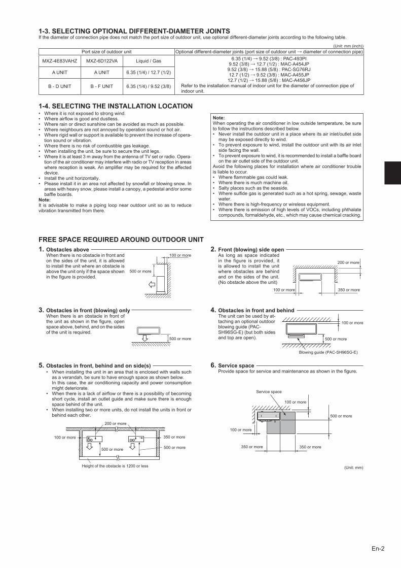
1-3. SELECTING OPTIONAL DIFFERENT-DIAMETER JOINTSIf the diameter of connection pipe does not match the port size of outdoor unit, use optional different-diameter joints according to the following table.
Port size of outdoor unit Optionaldifferent-diameterjoints(portsizeofoutdoorunit→diameterofconnectionpipe)
MXZ-4E83VAHZ MXZ-6D122VA Liquid/Gas 6.35(1/4)→9.52(3/8):PAC-493PI9.52(3/8)→12.7(1/2):MAC-A454JP9.52(3/8)→15.88(5/8):PAC-SG76RJ12.7(1/2)→9.52(3/8):MAC-A455JP12.7(1/2)→15.88(5/8):MAC-A456JP
Refer to the installation manual of indoor unit for the diameter of connection pipe of indoor unit.
A UNIT A UNIT 6.35(1/4)/12.7(1/2)
B - D UNIT B - F UNIT 6.35(1/4)/9.52(3/8)
1-4. SELECTING THE INSTALLATION LOCATION• Whereitisnotexposedtostrongwind.• Whereairflowisgoodanddustless.• Whererainordirectsunshinecanbeavoidedasmuchaspossible.• Whereneighboursarenotannoyedbyoperationsoundorhotair.• Whererigidwallorsupportisavailabletopreventtheincreaseofopera-
tion sound or vibration.• Wherethereisnoriskofcombustiblegasleakage.• Wheninstallingtheunit,besuretosecuretheunitlegs.• Whereitisatleast3mawayfromtheantennaofTVsetorradio.Opera-
tion of the air conditioner may interfere with radio or TV reception in areas wherereceptionisweak.Anamplifiermayberequiredfortheaffecteddevice.
• Installtheunithorizontally.• Pleaseinstallitinanareanotaffectedbysnowfallorblowingsnow.In
areaswithheavysnow,pleaseinstallacanopy,apedestaland/orsomebaffleboards.
Note:It is advisable to make a piping loop near outdoor unit so as to reduce vibration transmitted from there.
Note: When operating the air conditioner in low outside temperature, be sure to follow the instructions described below.• Neverinstalltheoutdoorunitinaplacewhereitsairinlet/outletside
may be exposed directly to wind.• Topreventexposuretowind,installtheoutdoorunitwithitsairinlet
side facing the wall.• Topreventexposuretowind,itisrecommendedtoinstallabaffleboard
on the air outlet side of the outdoor unit.Avoid the following places for installation where air conditioner trouble is liable to occur.• Whereflammablegascouldleak.• Wherethereismuchmachineoil.• Saltyplacessuchastheseaside.• Wheresulfidegasisgeneratedsuchasahotspring,sewage,waste
water.• Wherethereishigh-frequencyorwirelessequipment.• WherethereisemissionofhighlevelsofVOCs,includingphthalate
compounds, formaldehyde, etc., which may cause chemical cracking.
(Unit:mm(inch))
3. Obstacles in front (blowing) onlyWhen there is an obstacle in front of theunitasshowninthefigure,openspace above, behind, and on the sides of the unit is required.
2. Front (blowing) side openAs long as space indicated in the figure is provided, it is allowed to install the unit where obstacles are behind and on the sides of the unit. (Noobstacleabovetheunit)
FREE SPACE REQUIRED AROUND OUTDOOR UNIT
500ormore
200ormore
350ormore100ormore
1. Obstacles aboveWhen there is no obstacle in front and on the sides of the unit, it is allowed to install the unit where an obstacle is above the unit only if the space shown inthefigureisprovided.
100ormore
500ormore
100ormore
Service space
350ormore350ormore
6. Service spaceProvidespaceforserviceandmaintenanceasshowninthefigure.
500ormore
100ormore
• Wheninstallingtheunitinanareathatisenclosedwithwallssuchas a verandah, be sure to have enough space as shown below.
In this case, the air conditioning capacity and power consumption might deteriorate.
• Whenthereisalackofairfloworthereisapossibilityofbecomingshort cycle, install an outlet guide and make sure there is enough space behind of the unit.
• Wheninstallingtwoormoreunits,donotinstalltheunitsinfrontorbehind each other.
100ormore
200ormore
350ormore
500ormore 500ormore
(Unit:mm)
5. Obstacles in front, behind and on side(s)
4. Obstacles in front and behindThe unit can be used by at-taching an optional outdoor blowingguide(PAC-SH96SG-E)(butbothsidesandtopareopen).
100ormore
500ormore
Blowingguide(PAC-SH96SG-E)
Heightoftheobstacleis1200orless
BH79A198H01_en.indd 2 6/2/2015 5:48:27 PM
En-3
*2
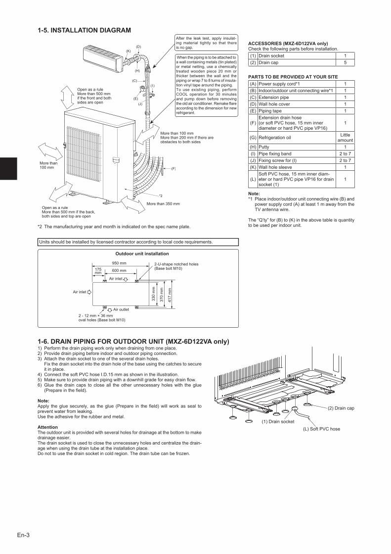
1-5. INSTALLATION DIAGRAM
Units should be installed by licensed contractor according to local code requirements.
After the leak test, apply insulat-ing material tightly so that there is no gap.
ACCESSORIES (MXZ-6D122VA only)Check the following parts before installation.(1) Drain socket 1(2) Drain cap 5
PARTS TO BE PROVIDED AT YOUR SITE(A) Power supply cord*1 1(B) Indoor/outdoorunitconnectingwire*1 1(C) Extension pipe 1(D) Wall hole cover 1(E) Piping tape 1
(F)Extension drain hose (orsoftPVChose,15mminnerdiameterorhardPVCpipeVP16)
1
(G) Refrigeration oil Little amount
(H) Putty 1(I) Pipefixingband 2to7(J) Fixingscrewfor(I) 2to7(K) Wall hole sleeve 1
(L)SoftPVChose,15mminnerdiam-eterorhardPVCpipeVP16fordrainsocket(1)
1
Note:*1 Placeindoor/outdoorunitconnectingwire(B)and
powersupplycord(A)atleast1mawayfromtheTV antenna wire.
The“Q’ty”for(B)to(K)intheabovetableisquantityto be used per indoor unit.
More than 100mm
Open as a ruleMorethan500mmif the front and both sides are open
Morethan100mmMorethan200mmifthereareobstacles to both sides
Open as a ruleMorethan500mmiftheback,both sides and top are open
Morethan350mm
Outdoor unit installation
Air inlet
Air outlet
Air inlet
950mm
600mm175mm
2-U-shapenotchedholes(BaseboltM10)
330mm
2-12mm×36mm ovalholes(BaseboltM10)
370mm
417mm
When the piping is to be attached to awallcontainingmetals(tinplated)or metal netting, use a chemically treatedwooden piece 20mm orthicker between the wall and the pipingorwrap7to8turnsofinsula-tion vinyl tape around the piping.To use existing piping, perform COOL operation for 30minutesand pump down before removing theoldairconditioner.Remakeflareaccording to the dimension for new refrigerant.
1-6. DRAIN PIPING FOR OUTDOOR UNIT (MXZ-6D122VA only)
(1)Drainsocket(L)SoftPVChose
(2)Draincap
1) Performthedrainpipingworkonlywhendrainingfromoneplace.2) Providedrainpipingbeforeindoorandoutdoorpipingconnection.3) Attachthedrainsockettooneoftheseveraldrainholes. Fix the drain socket into the drain hole of the base using the catches to secure
it in place.4) ConnectthesoftPVChoseI.D.15mmasshownintheillustration.5) Makesuretoprovidedrainpipingwithadownhillgradeforeasydrainflow.6) Glue thedrain caps to closeall theother unnecessaryholeswith theglue
(Prepareinthefield).
Note:Apply thegluesecurely,as theglue (Prepare in thefield)willworkasseal toprevent water from leaking.Use the adhesive for the rubber and metal.
AttentionThe outdoor unit is provided with several holes for drainage at the bottom to make drainage easier. The drain socket is used to close the unnecessary holes and centralize the drain-age when using the drain tube at the installation place.Do not to use the drain socket in cold region. The drain tube can be frozen.
*2 Themanufacturingyearandmonthisindicatedonthespecnameplate.
BH79A198H01_en.indd 3 6/2/2015 5:48:27 PM
En-4
A B C
D E F
A B C
D E F
A B C
E F
A B C
D E F
A B C
D D E F
P P P P P
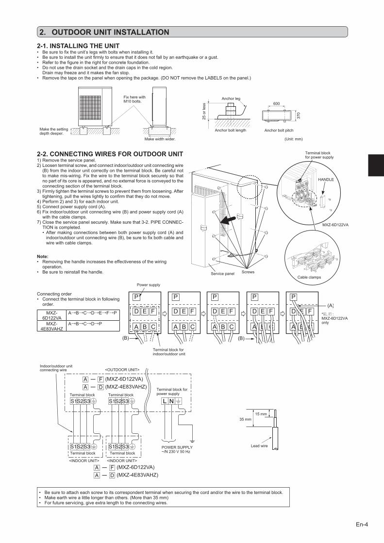
2-1. INSTALLING THE UNIT
Fix here with M10bolts.
Make the setting depth deeper.
Make width wider.
Anchor leg
25orless
Anchor bolt length Anchor bolt pitch
(Unit:mm)
2-2. CONNECTING WIRES FOR OUTDOOR UNIT
35mm15mm
Lead wire
• Besuretoattacheachscrewtoitscorrespondentterminalwhensecuringthecordand/orthewiretotheterminalblock.• Makeearthwirealittlelongerthanothers.(Morethan35mm)• Forfutureservicing,giveextralengthtotheconnectingwires.
Terminal block for power supply
• Besuretofixtheunit’slegswithboltswheninstallingit.• Besuretoinstalltheunitfirmlytoensurethatitdoesnotfallbyanearthquakeoragust.• Refertothefigureintherightforconcretefoundation.• Donotusethedrainsocketandthedraincapsinthecoldregion. Drain may freeze and it makes the fan stop.• Removethetapeonthepanelwhenopeningthepackage.(DONOTremovetheLABELSonthepanel.)
1)Removetheservicepanel.2)Loosenterminalscrew,andconnectindoor/outdoorunitconnectingwire
(B)fromtheindoorunitcorrectlyontheterminalblock.Becarefulnotto make mis-wiring. Fix the wire to the terminal block securely so that no part of its core is appeared, and no external force is conveyed to the connecting section of the terminal block.
3)Firmlytightentheterminalscrewstopreventthemfromloosening.Aftertightening,pullthewireslightlytoconfirmthattheydonotmove.
4)Perform2)and3)foreachindoorunit.5)Connectpowersupplycord(A).6)Fixindoor/outdoorunitconnectingwire(B)andpowersupplycord(A)
with the cable clamps.7)Closetheservicepanelsecurely.Makesurethat3-2.PIPECONNEC-
TION is completed.• Aftermakingconnectionsbetweenbothpowersupplycord(A)andindoor/outdoorunitconnectingwire(B),besuretofixbothcableandwire with cable clamps.
Connecting order• Connecttheterminalblockinfollowing
order.
MXZ-6D122VA
A→B→C→D→E→F→P
MXZ-4E83VAHZ
A→B→C→D→P
Power supply
Terminal block for indoor/outdoorunit
*E, F:MXZ-6D122VAonly
D
D (MXZ-4E83VAHZ)(MXZ-6D122VA)
(MXZ-4E83VAHZ)(MXZ-6D122VA)
<OUTDOOR UNIT>Indoor/outdoorunitconnecting wire
<INDOOR UNIT>
Terminal block
POWERSUPPLY~/N230V50HzTerminal block Terminal block
Terminal block for power supplyTerminal block
<INDOOR UNIT>
Cable clamps
600
370
Service panel Screws
Note:• Removingthehandleincreasestheeffectivenessofthewiring
operation.• Besuretoreinstallthehandle.
2. OUTDOOR UNIT INSTALLATION
HANDLE
MXZ-6D122VA
BH79A198H01_en.indd 4 6/2/2015 5:48:28 PM
En-5
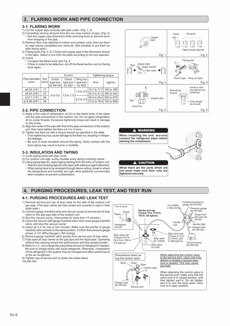
Fig. 1 Fig.2
Fig.3 Fig.4
Fig.5 Fig.6
3-1. FLARING WORK
Pipe diameter (mm)
Nut (mm)
A(mm) Tightening torqueClutch
type tool forR410A
Clutch type tool forR22
Wing nut type tool forR22
N•m kgf•cm
ø6.35(1/4”) 17
0to0.5 1.0to1.51.5to2.0
13.7to17.7 140to180ø9.52(3/8”) 22 34.3to41.2 350to420ø12.7(1/2”) 26
2.0to2.549.0to56.4 500to575
ø15.88(5/8”) 29 73.5to78.4 750to800
Tilted Uneven Burred
Good No good
Burr Copper pipeSpare reamer
Pipe cutter
Smooth all around
Even length all around
Inside is shin-ing without any scratches.
Flare nut
DieCopper pipe
Clutch type
Flaring tool
Wing nut type
3-2. PIPE CONNECTION1)Applyathincoatofrefrigerationoil(G)totheflaredendsofthepipes
and the pipe connections of the outdoor unit. Do not apply refrigeration oil on screw threads. Excessive tightening torque will result in damage on the screw.
2)Alignthecenterofthepipewiththatofthepipeconnectionsoftheoutdoorunit,thenhandtightentheflarenut3to4turns.
3)Tightentheflarenutwithatorquewrenchasspecifiedinthetable.• Over-tighteningmaycausedamagetotheflarenut,resultinginrefriger-
ant leakage.• Besuretowrapinsulationaroundthepiping.Directcontactwiththe
bare piping may result in burns or frostbite.
3-3. INSULATION AND TAPING1)Coverpipingjointswithpipecover.2)Foroutdoorunitside,surelyinsulateeverypipingincludingvalves.3)Usingpipingtape(E),applytapingstartingfromtheentryofoutdoorunit.
• Stoptheendofpipingtape(E)withtape(withadhesiveagentattached).•Whenpipinghavetobearrangedthroughaboveceiling,closetorwhere
the temperature and humidity are high, wind additional commercially sold insulation to prevent condensation.
Copper pipe
1)Cutthecopperpipecorrectlywithpipecutter.(Fig.1,2)2)Completelyremoveallburrsfromthecutcrosssectionofpipe.(Fig.3)
• Aimthecopperpipedownwardwhileremovingburrstopreventburrsfrom dropping in the pipe.
3)Removeflarenutsattachedtoindoorandoutdoorunits,thenputthemonpipehavingcompletedburrremoval.(Notpossibletoputthemonafterflaringwork.)
4)Flaringwork(Fig.4,5).Firmlyholdcopperpipeinthedimensionshownin the table. Select A mm from the table according to the tool selected.
5)Check• ComparetheflaredworkwithFig.6.• Ifflareisnotedtobedefective,cutofftheflaredsectionanddoflaring
work again.
WARNINGWhen installing the unit, securely connect the refrigerant pipes before starting the compressor.
CAUTIONWhen there are the ports which are not used, make sure their nuts are tightened securely.
4-1. PURGING PROCEDURES AND LEAK TEST1)Removeserviceportcapofstopvalveonthesideoftheoutdoorunit
gaspipe.(Thestopvalvesarefullyclosedandcoveredincapsintheirinitialstate.)
2)Connectgaugemanifoldvalveandvacuumpumptoserviceportofstopvalve on the gas pipe side of the outdoor unit.
3)Runthevacuumpump.(Vacuumizeformorethan15minutes.)4)Checkthevacuumwithgaugemanifoldvalve,thenclosegaugemanifold
valve, and stop the vacuum pump.5)Leaveasitisforoneortwominutes.Makesurethepointerofgauge
manifoldvalveremainsinthesameposition.Confirmthatpressuregaugeshows-0.101MPa[Gauge](-760mmHg).
6)Removegaugemanifoldvalvequicklyfromserviceportofstopvalve.7)Fullyopenallstopvalvesonthegaspipeandtheliquidpipe.Operating
without fully opening lowers the performance and this causes trouble.8)Referto1-2.,andchargetheprescribedamountofrefrigerantifneeded.
Be sure to charge slowly with liquid refrigerant. Otherwise, composition of the refrigerant in the system may be changed and affect performance of the air conditioner.
9)Tightencapofserviceporttoobtaintheinitialstatus.10)Leaktest
Stop valve forGAS
Gaugemani-foldvalve(forR410A)
Compound pressure gauge(forR410A)–0.101MPa
(–760mmHg)
HandleLow HandleHigh
Vacuum pump(forR410A)
Charge hose (forR410A)
*Close*Open
Hexagonalwrench
*4to5turns
Stop valve for LIQUID
Pressure gauge(forR410A)
Precautions when us-ing the control valve
When attaching the control valve to the service port, valve core may deform or loosen if excess pres-sure is applied. This may cause gas leak.
Service port
Charge hose (forR410A)
Body CloseOpen
Control valveA
When attaching the control valve to the service port, make sure that the valve core is in closed position, and then tighten part A. Do not tighten part A or turn the body when valve core is in open position.
4. PURGING PROCEDURES, LEAK TEST, AND TEST RUN
Stop valve cap(Torque24.4to30.4N•m,250to310kgf•cm)
Service port cap(Torque10to12N•m,100to120kgf•cm)
Service port cap(Torque10to12N•m,100to120kgf•cm)
Stop valve cap(Torque21.5to27.5N•m,220to280kgf•cm)
3. FLARING WORK AND PIPE CONNECTION
BH79A198H01_en.indd 5 6/2/2015 5:48:29 PM
En-6
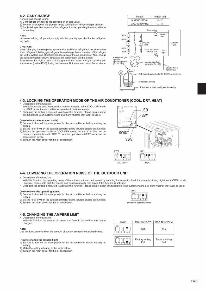
4-3. LOCKING THE OPERATION MODE OF THE AIR CONDITIONER (COOL, DRY, HEAT)
4-4. LOWERING THE OPERATION NOISE OF THE OUTDOOR UNIT
4-2. GAS CHARGEPerform gas charge to unit.1)Connectgascylindertotheserviceportofstopvalve.2)Performairpurgeofthepipe(orhose)comingfromrefrigerantgascylinder.3)Replenishspecifiedamountoftherefrigerant,whileoperatingtheairconditioner
for cooling.
Note:Incaseofaddingrefrigerant,complywiththequantityspecifiedfortherefrigerat-ing cycle.
CAUTION:When charging the refrigerant system with additional refrigerant, be sure to use liquid refrigerant. Adding gas refrigerant may change the composition of the refriger-ant in the system and affect normal operation of the air conditioner. Also, charge the liquid refrigerant slowly, otherwise the compressor will be locked.To maintain the high pressure of the gas cylinder, warm the gas cylinder with warmwater(under40°C)duringcoldseason.Butneverusenakedfireorsteam.
COOL/DRY HEAT
• Descriptionofthefunction: Withthisfunction,oncetheoperationmodeislockedtoeitherCOOL/DRYmode
orHEATmode,theairconditioneroperatesinthatmodeonly.* Changing the setting is required to activate this function. Please explain about
this function to your customers and ask them whether they want to use it.
[How to lock the operation mode]1)Besure to turnoff themainpower for theairconditionerbeforemaking the
setting.2)Setthe“3”ofSW1ontheoutdoorcontrollerboardtoONtoenablethisfunction.3)TolocktheoperationmodeinCOOL/DRYmode,set the“4”ofSW1onthe
outdoorcontrollerboardtoOFF.TolocktheoperationinHEATmode,setthesame switch to ON.
4)Turnonthemainpowerfortheairconditioner.
• Descriptionofthefunction: With this function, the operating noise of the outdoor unit can be lowered by reducing the operation load, for example, during nighttime in COOL mode.
However,pleasenotethatthecoolingandheatingcapacitymaylowerifthisfunctionisactivated.* Changing the setting is required to activate this function. Please explain about this function to your customers and ask them whether they want to use it.
Union
Stop valve
Liquid pipe
Indoor unit
Stop valve with service port Gas
pipe
Refrigerant gas cylinder operating valve(forR410A)
Gaugemanifoldvalve(forR410A)
Charge hose (forR410A)
RefrigerantgascylinderforR410Awithsiphon
Electronic scale for refrigerant charging
Refrigerant(liquid)
Outdoor unit
Union
Union
Union
4-5. CHANGING THE AMPERE LIMIT• Descriptionofthefunction: Withthisfunction,theamountofcurrentthatflowsintheoutdoorunitcanbe
changed.
Note:Use this function only when the amount of current exceeds the allowed value.
[How to change the ampere limit]1)Besure to turnoff themainpower for theairconditionerbeforemaking the
setting.2)Makethesettingreferringtothetablebelow.3)Turnonthemainpowerfortheairconditioner.
SW2 MXZ-6D122VA MXZ-4E83VAHZON
1 2 3 4 5 620A 21A
ON
1 2 3 4 5 6
Factory setting Full
Factory setting Full
SW1ON
1 2 3 4 5 6
SW1ON
1 2 3 4 5 6
SW1ON
1 2 3 4 5 6
Lower the operating noise
[How to lower the operating noise]1)Besure to turnoff themainpower for theairconditionerbeforemaking the
setting.2)Setthe“5”ofSW1ontheoutdoorcontrollerboardtoONtoenablethisfunction.3)Turnonthemainpowerfortheairconditioner.
LEDSW1
SW871SW2
Model Indoor unitMXZ-6D122VA A - FMXZ-4E83VAHZ A - D
BH79A198H01_en.indd 6 6/2/2015 5:48:29 PM
En-7
4-6. TEST RUN• Testrunsoftheindoorunitsshouldbeperformedindividually.Seetheinstallationmanualcomingwiththeindoorunit,andmakesurealltheunitsoperate
properly.• Ifthetestrunwithalltheunitsisperformedatonce,possibleerroneousconnectionsoftherefrigerantpipesandtheindoor/outdoorunitconnectingwires
cannot be detected. Thus, be sure to perform the test run one by one.
About the restart protective mechanismOncethecompressorstops,therestartpreventivedeviceoperatessothecompressorwillnotoperatefor3minutestoprotecttheairconditioner.
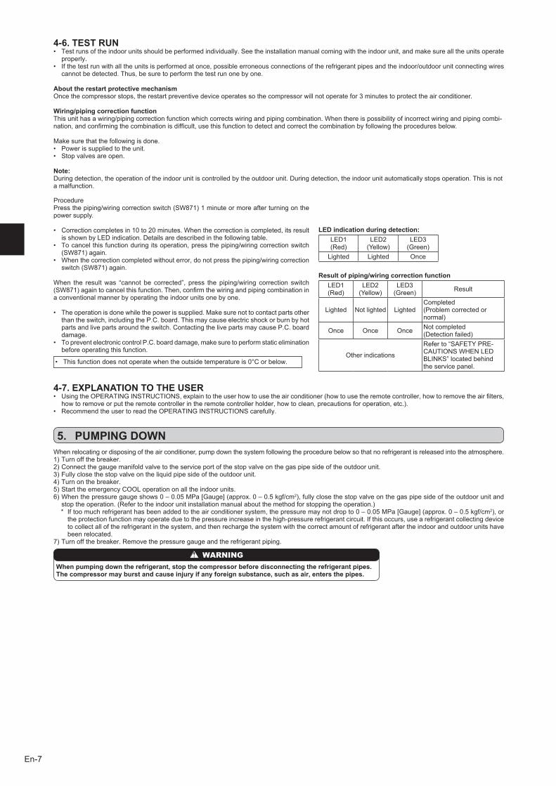
Wiring/piping correction functionThisunithasawiring/pipingcorrectionfunctionwhichcorrectswiringandpipingcombination.Whenthereispossibilityofincorrectwiringandpipingcombi-nation,andconfirmingthecombinationisdifficult,usethisfunctiontodetectandcorrectthecombinationbyfollowingtheproceduresbelow.
Make sure that the following is done.• Powerissuppliedtotheunit.• Stopvalvesareopen.
Note:During detection, the operation of the indoor unit is controlled by the outdoor unit. During detection, the indoor unit automatically stops operation. This is not a malfunction.
ProcedurePressthepiping/wiringcorrectionswitch(SW871)1minuteormoreafterturningonthepower supply.
• Correctioncompletesin10to20minutes.Whenthecorrectioniscompleted,itsresultis shown by LED indication. Details are described in the following table.
• Tocancelthisfunctionduringitsoperation,pressthepiping/wiringcorrectionswitch(SW871)again.
• Whenthecorrectioncompletedwithouterror,donotpressthepiping/wiringcorrectionswitch(SW871)again.
When the resultwas “cannot be corrected”, press the piping/wiring correction switch(SW871)againtocancelthisfunction.Then,confirmthewiringandpipingcombinationina conventional manner by operating the indoor units one by one.
• Theoperationisdonewhilethepowerissupplied.Makesurenottocontactpartsotherthan the switch, including the P.C. board. This may cause electric shock or burn by hot parts and live parts around the switch. Contacting the live parts may cause P.C. board damage.
• TopreventelectroniccontrolP.C.boarddamage,makesuretoperformstaticeliminationbefore operating this function.
• Thisfunctiondoesnotoperatewhentheoutsidetemperatureis0°Corbelow.
LED indication during detection:LED1 (Red)
LED2(Yellow)
LED3(Green)
Lighted Lighted Once
Result of piping/wiring correction functionLED1 (Red)
LED2(Yellow)
LED3(Green) Result
Lighted Not lighted LightedCompleted(Problemcorrectedornormal)
Once Once Once Not completed (Detectionfailed)
Other indications
Referto“SAFETYPRE-CAUTIONSWHENLEDBLINKS”locatedbehindthe service panel.
4-7. EXPLANATION TO THE USER• UsingtheOPERATINGINSTRUCTIONS,explaintotheuserhowtousetheairconditioner(howtousetheremotecontroller,howtoremovetheairfilters,
howtoremoveorputtheremotecontrollerintheremotecontrollerholder,howtoclean,precautionsforoperation,etc.).• RecommendtheusertoreadtheOPERATINGINSTRUCTIONScarefully.
When relocating or disposing of the air conditioner, pump down the system following the procedure below so that no refrigerant is released into the atmosphere.1)Turnoffthebreaker.2)Connectthegaugemanifoldvalvetotheserviceportofthestopvalveonthegaspipesideoftheoutdoorunit.3)Fullyclosethestopvalveontheliquidpipesideoftheoutdoorunit.4)Turnonthebreaker.5)StarttheemergencyCOOLoperationonalltheindoorunits.6)Whenthepressuregaugeshows0–0.05MPa[Gauge](approx.0–0.5kgf/cm2),fullyclosethestopvalveonthegaspipesideoftheoutdoorunitand
stoptheoperation.(Refertotheindoorunitinstallationmanualaboutthemethodforstoppingtheoperation.) * Iftoomuchrefrigeranthasbeenaddedtotheairconditionersystem,thepressuremaynotdropto0–0.05MPa[Gauge](approx.0–0.5kgf/cm2),or
the protection function may operate due to the pressure increase in the high-pressure refrigerant circuit. If this occurs, use a refrigerant collecting device to collect all of the refrigerant in the system, and then recharge the system with the correct amount of refrigerant after the indoor and outdoor units have been relocated.
7)Turnoffthebreaker.Removethepressuregaugeandtherefrigerantpiping.
When pumping down the refrigerant, stop the compressor before disconnecting the refrigerant pipes.The compressor may burst and cause injury if any foreign substance, such as air, enters the pipes.
WARNING
5. PUMPING DOWN
BH79A198H01_en.indd 7 6/2/2015 5:48:29 PM
BH79A198H01
HEAD OFFICE: TOKYO BLDG., 2-7-3, MARUNOUCHI, CHIYODA-KU, TOKYO 100-8310, JAPAN
MITSUBISHI ELECTRIC CONSUMER PRODUCTS (THAILAND) CO., LTDAMATA NAKORN INDUSTRIAL ESTATE 700/406 MOO 7, TAMBON DON HUA ROH, AMPHUR MUANG, CHONBURI 20000, THAILAND
hereby declares under its sole responsibility that the air conditioners and heat pumps described below for use in residential, commercial and light-industrial environments:erklärt hiermit auf seine alleinige Verantwortung, dass die Klimaanlagen und Wärmepumpen für das häusliche, kommerzielle und leicht-industrielle Umfeld wie unten beschrieben:déclare par la présente et sous sa propre responsabilité que les climatiseurs et les pompes à chaleur décrits ci-dessous, destinés à un usage dans des environnements résidentiels, commerciaux et d’industrie légère :verklaart hierbij onder eigen verantwoordelijkheid dat de voor residentiële, commerciële en licht-industriële omgevingen bestemde airconditioners en warmtepompen zoals onderstaand beschreven:por la presente declara bajo su única responsabilidad que los acondicionadores de aire y bombas de calor descritas a continuación para su uso en entornos residenciales, comerciales y de industria ligera:conferma con la presente, sotto la sua esclusiva responsabilità, che i condizionatori d’aria e le pompe di calore descritti di seguito e destinati all’utilizzo in ambienti residenziali, commer-ciali e semi-industriali:με το παρόν πιστοποιεί με αποκλειστική της ευθύνη ότι οι τα κλιματιστικά και οι αντλίες θέρμανσης που περιγράφονται παρακάτω για χρήση σε οικιακό, επαγγελματικό και ελαφριάς βιομηχανίας περιβάλλοντα:através da presente declara sob sua única responsabilidade que os aparelhos de ar condicionado e bombas de calor abaixo descritos para uso residencial, comercial e de indústria ligeira:erklærer hermed under eneansvar, at de herunder beskrevne airconditionanlæg og varmepumper til brug i privat boligbyggeri, erhvervsområder og inden for let industri:intygar härmed att luftkonditioneringarna och värmepumparna som beskrivs nedan för användning i bostäder, kommersiella miljöer och lätta industriella miljöer:ev, ticaret ve hafif sanayi ortamlarında kullanım amaçlı üretilen ve aşağıda açıklanan klima ve ısıtma pompalarıyla ilgili aşağıdaki hususları yalnızca kendi sorumluluğunda beyan eder:настоящим заявляет и берет на себя исключительную ответственность за то, что кондиционеры и тепловые насосы, описанные ниже и предназначенные для эксплуатации в жилых помещениях, торговых залах и на предприятиях легкой промышленности:erklærer et fullstendig ansvar for undernevnte klimaanlegg og varmepumper ved bruk i boliger, samt kommersielle og lettindustrielle miljøer: vakuuttaa täten yksinomaisella vastuullaan, että jäljempänä kuvatut asuinrakennuksiin, pienteollisuuskäyttöön ja kaupalliseen käyttöön tarkoitetut ilmastointilaitteet ja lämpöpumput:декларира на своя собствена отговорност, че климатиците и термопомпите, описани по-долу, за употреба в жилищни, търговски и леки промишлени условия:
Note: Its serial number is on the nameplate of the product.Hinweis: Die Seriennummer befindet sich auf dem Kennschild des Produkts.Remarque : Le numéro de série de l’appareil se trouve sur la plaque du produit.Opmerking: het serienummer staat op het naamplaatje van het product.Nota: El número de serie se encuentra en la placa que contiene el nombre del producto.Nota: il numero di serie si trova sulla targhetta del prodotto.Σημείωση: Ο σειριακός του αριθμός βρίσκεται στην πινακίδα ονόματος του προϊόντος.Nota: o número de série encontra-se na placa que contém o nome do produto.
Bemærk: Serienummeret står på produktets fabriksskilt.Obs: Serienumret finns på produktens namnplåt.Not: Seri numarası ürünün isim plakasında yer alır.Примечание: серийный номер указан на паспортное табличке изделия.Merk: Serienummeret befinner seg på navneplaten til produktet. Huomautus: Sarjanumero on merkitty laitteen arvokilpeen.Забележка: Серийният му номер е на табелката на продукта.
DirectivesRichtlinienDirectivesRichtlijnenDirectivasDirettiveΟδηγίεςDirectivas
DirektiverDirektivDirektiflerДирективыDirektiver DirektiivitДирективи
Our authorized representative in EU, who is authorized to compile the technical file, is as follows.Unser autorisierter Vertreter in der EU, der ermächtigt ist die technischen Daten zu kompilieren, ist wie folgt.Notre représentant agréée dans L’UE, qui est autorisé à compiler le fichier technique, est le suivant.Onze geautoriseerde vertegenwoordiger in de EU, die gemachtigd is het technische bestand te com-pileren, is als volgt.Nuestro representante autorizado en la UE, que está autorizado para compilar el archivo técnico, es el siguiente.Il nostro rivenditore autorizzato nell’UE, responsabile della stesura della scheda tecnica, è il seguente.Ο εξουσιοδοτημένος αντιπρόσωπός μας στην ΕΕ, ο οποίος είναι εξουσιοδοτημένος να συντάξει τον τεχνικό φάκελο, είναι ο εξής.O nosso representante autorizado na UE, que está autorizado para compilar o ficheiro técnico, é o seguinte:
Vores autoriserede repræsentant i EU, som er autoriseret til udarbejdelse af den tekniske fil, er føl-gende.Vår EG-representant som är auktoriserad att sammanställa den tekniska filen är följande.Avrupa Birliği’nde bulunan ve teknik dosyayı düzenleme yetkisine sahip yetkili temsilcimiz aşağıda belirtilmiştir:Наш авторизованный представитель в ЕС, уполномоченный на составление технического фай-ла, указан ниже.Vår autoriserte EU-representant, som har autorisasjon til å utarbeide denne tekniske filen, er som følger.Valtuutettu EU-edustaja, joka on valtuutettu laatimaan teknisen eritelmän, on mainittu alla.Наш упълномощен представител в ЕС, който е упълномощен да състави техническото досие, е както следва.
MITSUBISHI ELECTRIC EUROPE, B.V.HARMAN HOUSE, 1 GEORGE STREET, UXBRIDGE, MIDDLESEX UB8 1QQ, U.K.Masahiko KONISHIProduct Marketing Director
Issued: 15, Jun, 2015 Tomoyuki MIWATHAILAND Manager, Quality Assurance Department
MITSUBISHI ELECTRIC, MXZ-6D122VA, MXZ-4E83VAHZ
EC DECLARATION OF CONFORMITYEG-KONFORMITÄTSERKLÄRUNGDÉCLARATION DE CONFORMITÉ CEEG-CONFORMITEITSVERKLARING
DECLARACIÓN DE CONFORMIDAD CEDICHIARAZIONE DI CONFORMITÀ CEΔΗΛΩΣΗ ΠΙΣΤΟΤΗΤΑΣ ΕΚDECLARAÇÃO DE CONFORMIDADE CE
EU-OVERENSSTEMMELSESERKLÆRINGEG-DEKLARATION OM ÖVERENSSTÄMMELSEEC UYGUNLUK BEYANIДЕКЛАРАЦИЯ СООТВЕТСТВИЯ НОРМАМ ЕС
CE-ERKLÆRING OM SAMSVAREY-VAATIMUSTENMUKAISUUSVAKUUTUSДЕКЛАРАЦИЯ ЗА СЪОТВЕТСТВИЕ
2006/95/EC: Low Voltage Directive2006/42/EC: Machinery Directive2004/108/EC: Electromagnetic Compatibility Directive2009/125/EC: Energy-related Products Directive and Regulation (EU) No 206/2012
BH79A198H01_cover4.indd 1 6/1/2015 9:00:19 AM