Split-type Air-Conditioner · Split-type Air-Conditioner MXZ-3DM50VA Türkçe Svenska Dansk...
8
Split-type Air-Conditioner MXZ-3DM50VA Türkçe Svenska Dansk Português Ελληνικά Italiano Español Nederlands Français Deutsch English Installation Manual For INSTALLER • This manual only describes the installation of outdoor unit. When installing the indoor unit, refer to the installation manual of indoor unit. Installationsanleitung Für INSTALLATEUR • Diese Installationsanleitung gilt nur für die Installation des Außengerätes. Zur Installation des Innengeräts siehe die Installationsanleitung für Innengeräte. Notice d’installation Destinée à l’INSTALLATEUR • Cette notice ne décrit que l’installation de l’appareil extérieur. Lors de l’installation de l’appareil intérieur, consultez la notice d’installation de cet appareil. Installatiehandleiding Voor de INSTALLATEUR • Deze handleiding beschrijft alleen de installatie van de buitenunit. Raadpleeg de installatiehandleiding van de binnenunit wanneer u deze instal- leert. Manual de instalación Para el INSTALADOR • En este manual sólo se describe la instalación de la unidad exterior. Para instalar la unidad interior, consulte el manual de instalación de dicha uni- dad. Manuale per l’installazione Per il TECNICO INSTALLATORE • Questo manuale descrive solo l’installazione dell’unità esterna. Per l’installazione dell’unità interna, fare riferimento al relativo manuale di instal- lazione. Εγχειρίδιο εγκατάστασης Για τον ΤΕΧΝΙΚΟ • Στο παρόν εγχειρίδιο περιγράφεται μόνο η εγκατάσταση της μονάδας εξωτερικού χώρου. Για την εγκατάσταση της μονάδας εσωτερικού χώρου, ανατρέξτε στο εγχειρίδιο εγκατάστασης της μονάδας εσωτερικού χώρου. Manual de Instalação Para o INSTALADOR • Este manual descreve apenas a instalação da unidade exterior. Quando proceder à instalação da unidade interior, consulte o manual de instalação da unidade interior. Installationshåndbog Til INSTALLATØREN • Denne håndbog beskriver kun, hvordan udendørsenheden installeres. Vedrørende installation af indendørsenheden henvises til installationshåndbogen for indendørsenheden. Installationsanvisning För INSTALLATÖREN • Denna installationsanvisning beskriver endast installation av utomhusenheten. Se den separata installationsanvisningen för inomhusenheten. Kurulum Kılavuzu TESİSATÇI İÇİN • Bu kılavuzda yalnızca dış ünitenin kurulumu açıklanmaktadır. İç ünite kurulum işlemini yaparken iç ünite kurulum kılavuzuna bakın. Ръководство за монтаж За ИНСТАЛАТОРА • Това ръководство описва само монтажа на външното тяло. При монтиране на вътрешното тяло вижте ръководството за монтаж на вътрешното тяло. English is original. Übersetzung des Originals Traduction du texte d’origine Vertaling van het origineel Traducción del original Traduzione dell’originale Μετάφραση του αρχικού Tradução do original Oversættelse af den originale tekst Översättning från originalet Orijinalin çevirisi Версията на английски език е оригинал. Български
Transcript of Split-type Air-Conditioner · Split-type Air-Conditioner MXZ-3DM50VA Türkçe Svenska Dansk...
Split-type Air-ConditionerMXZ-3DM50VA
Türkçe
Svenska
Dansk
Português
Ελληνικά
Italiano
Español
Nederlands
Français
Deutsch
EnglishInstallation Manual For INSTALLER• This manual only describes the installation of outdoor unit. When installing the indoor unit, refer to the installation manual of indoor unit.
Installationsanleitung Für INSTALLATEUR• Diese Installationsanleitung gilt nur für die Installation des Außengerätes. Zur Installation des Innengeräts siehe die Installationsanleitung für Innengeräte.
Notice d’installation Destinée à l’INSTALLATEUR• Cette notice ne décrit que l’installation de l’appareil extérieur. Lors de l’installation de l’appareil intérieur, consultez la notice d’installation de cet
appareil.
Installatiehandleiding Voor de INSTALLATEUR• Deze handleiding beschrijft alleen de installatie van de buitenunit. Raadpleeg de installatiehandleiding van de binnenunit wanneer u deze instal-
leert.
Manual de instalación Para el INSTALADOR• En este manual sólo se describe la instalación de la unidad exterior. Para instalar la unidad interior, consulte el manual de instalación de dicha uni-
dad.
Manuale per l’installazione Per il TECNICO INSTALLATORE• Questo manuale descrive solo l’installazione dell’unità esterna. Per l’installazione dell’unità interna, fare riferimento al relativo manuale di instal-
lazione.
Εγχειρίδιο εγκατάστασης ΓιατονΤΕΧΝΙΚΟ• Στοπαρόνεγχειρίδιοπεριγράφεταιμόνοηεγκατάστασητηςμονάδαςεξωτερικούχώρου. Για την εγκατάσταση τηςμονάδας εσωτερικούχώρου,ανατρέξτεστο εγχειρίδιοεγκατάστασηςτηςμονάδαςεσωτερικούχώρου.
Manual de Instalação Para o INSTALADOR• Este manual descreve apenas a instalação da unidade exterior. Quando proceder à instalação da unidade interior, consulte o manual de instalação
da unidade interior.
Installationshåndbog Til INSTALLATØREN• Denne håndbog beskriver kun, hvordan udendørsenheden installeres. Vedrørende installation af indendørsenheden henvises til installationshåndbogen
for indendørsenheden.
Installationsanvisning För INSTALLATÖREN• Denna installationsanvisning beskriver endast installation av utomhusenheten.
Se den separata installationsanvisningen för inomhusenheten.
Kurulum Kılavuzu TESİSATÇIİÇİN• Bukılavuzdayalnızcadışüniteninkurulumuaçıklanmaktadır. İçünitekurulumişleminiyaparkeniçünitekurulumkılavuzunabakın.
Ръководство за монтаж ЗаИНСТАЛАТОРА• Товаръководствоописвасамомонтажанавъншнототяло. Примонтиране на вътрешното тяло вижте ръководството замонтаж навътрешнототяло.
English is original.
Übersetzung des Originals
Traduction du texte d’origine
Vertaling van het origineel
Traducción del original
Traduzione dell’originale
Μετάφρασητουαρχικού
Tradução do original
Oversættelse af den originale tekst
Översättning från originalet
Orijinalin çevirisi
Версиятанаанглийскиезикеоригинал. Български
BH79A246H01_cover.indd 1 10/16/2015 9:22:16 AM
En-1
1. BEFORE INSTALLATION1-1. THE FOLLOWING SHOULD ALWAYS BE OBSERVED FOR SAFETY• Besuretoread“THEFOLLOWINGSHOULDALWAYSBEOBSERVEDFORSAFETY”beforeinstallingtheairconditioner.• Besuretoobservethewarningsandcautionsspecifiedhereastheyincludeimportantitemsrelatedtosafety.• Afterreadingthismanual,besuretokeepittogetherwiththeOPERATINGINSTRUCTIONSforfuturereference.• EquipmentcomplyingwithIEC/EN61000-3-12.
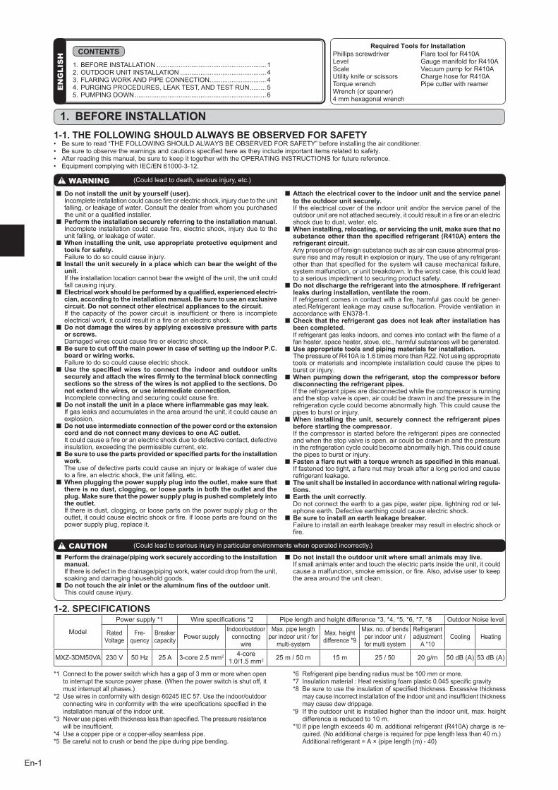
1-2. SPECIFICATIONS
CAUTION (Couldleadtoseriousinjuryinparticularenvironmentswhenoperatedincorrectly.)
n Do not install the unit by yourself (user). Incompleteinstallationcouldcausefireorelectricshock,injuryduetotheunit
falling,orleakageofwater.Consultthedealerfromwhomyoupurchasedtheunitoraqualifiedinstaller.
n Perform the installation securely referring to the installation manual. Incomplete installationcouldcausefire,electricshock, injuryduetothe
unitfalling,orleakageofwater.n When installing the unit, use appropriate protective equipment and
tools for safety. Failuretodosocouldcauseinjury.n Install the unit securely in a place which can bear the weight of the
unit. Iftheinstallationlocationcannotbeartheweightoftheunit,theunitcould
fallcausinginjury.n Electrical work should be performed by a qualified, experienced electri-
cian, according to the installation manual. Be sure to use an exclusive circuit. Do not connect other electrical appliances to the circuit.
If the capacity of thepower circuit is insufficient or there is incompleteelectricalwork,itcouldresultinafireoranelectricshock.
n Do not damage the wires by applying excessive pressure with parts or screws.
Damagedwirescouldcausefireorelectricshock.n Be sure to cut off the main power in case of setting up the indoor P.C.
board or wiring works. Failuretodosocouldcauseelectricshock.n Use the specified wires to connect the indoor and outdoor units
securely and attach the wires firmly to the terminal block connecting sections so the stress of the wires is not applied to the sections. Do not extend the wires, or use intermediate connection.
Incompleteconnectingandsecuringcouldcausefire.n Do not install the unit in a place where inflammable gas may leak. Ifgasleaksandaccumulatesintheareaaroundtheunit,itcouldcausean
explosion.n Do not use intermediate connection of the power cord or the extension
cord and do not connect many devices to one AC outlet. Itcouldcauseafireoranelectricshockduetodefectivecontact,defective
insulation,exceedingthepermissiblecurrent,etc.n Be sure to use the parts provided or specified parts for the installation
work. Theuseofdefectivepartscouldcauseaninjuryorleakageofwaterdue
toafire,anelectricshock,theunitfalling,etc.n When plugging the power supply plug into the outlet, make sure that
there is no dust, clogging, or loose parts in both the outlet and the plug. Make sure that the power supply plug is pushed completely into the outlet.
Ifthereisdust,clogging,orloosepartsonthepowersupplyplugortheoutlet,itcouldcauseelectricshockorfire.Ifloosepartsarefoundonthepowersupplyplug,replaceit.
n Attach the electrical cover to the indoor unit and the service panel to the outdoor unit securely.
Iftheelectricalcoveroftheindoorunitand/ortheservicepaneloftheoutdoorunitarenotattachedsecurely,itcouldresultinafireoranelectricshockduetodust,water,etc.
n When installing, relocating, or servicing the unit, make sure that no substance other than the specified refrigerant (R410A) enters the refrigerant circuit.
Anypresenceofforeignsubstancesuchasaircancauseabnormalpres-sureriseandmayresultinexplosionorinjury.Theuseofanyrefrigerantother than thatspecified for thesystemwillcausemechanical failure,systemmalfunction,orunitbreakdown.Intheworstcase,thiscouldleadtoaseriousimpedimenttosecuringproductsafety.
n Do not discharge the refrigerant into the atmosphere. If refrigerant leaks during installation, ventilate the room.
Ifrefrigerantcomesincontactwithafire,harmfulgascouldbegener-ated.Refrigerant leakagemaycausesuffocation.ProvideventilationinaccordancewithEN378-1.
n Check that the refrigerant gas does not leak after installation has been completed.
Ifrefrigerantgasleaksindoors,andcomesintocontactwiththeflameofafanheater,spaceheater,stove,etc.,harmfulsubstanceswillbegenerated.
n Use appropriate tools and piping materials for installation. ThepressureofR410Ais1.6timesmorethanR22.Notusingappropriate
toolsormaterialsandincompleteinstallationcouldcausethepipestoburstorinjury.
n When pumping down the refrigerant, stop the compressor before disconnecting the refrigerant pipes.
Iftherefrigerantpipesaredisconnectedwhilethecompressorisrunningandthestopvalveisopen,aircouldbedrawninandthepressureintherefrigerationcyclecouldbecomeabnormallyhigh.Thiscouldcausethepipestoburstorinjury.
n When installing the unit, securely connect the refrigerant pipes before starting the compressor.
Ifthecompressorisstartedbeforetherefrigerantpipesareconnectedandwhenthestopvalveisopen,aircouldbedrawninandthepressureintherefrigerationcyclecouldbecomeabnormallyhigh.Thiscouldcausethepipestoburstorinjury.
n Fasten a flare nut with a torque wrench as specified in this manual. Iffastenedtootight,aflarenutmaybreakafteralongperiodandcause
refrigerantleakage.n The unit shall be installed in accordance with national wiring regula-
tions. n Earth the unit correctly. Donotconnecttheearthtoagaspipe,waterpipe,lightningrodortel-
ephoneearth.Defectiveearthingcouldcauseelectricshock.n Be sure to install an earth leakage breaker. Failuretoinstallanearthleakagebreakermayresultinelectricshockor
fire.
n Perform the drainage/piping work securely according to the installation manual.
Ifthereisdefectinthedrainage/pipingwork,watercoulddropfromtheunit,soakinganddamaginghouseholdgoods.
n Do not touch the air inlet or the aluminum fins of the outdoor unit. Thiscouldcauseinjury.
n Do not install the outdoor unit where small animals may live. Ifsmallanimalsenterandtouchtheelectricpartsinsidetheunit,itcould
causeamalfunction,smokeemission,orfire.Also,adviseusertokeeptheareaaroundtheunitclean.
WARNING (Couldleadtodeath,seriousinjury,etc.)
*1 Connecttothepowerswitchwhichhasagapof3mmormorewhenopentointerruptthesourcepowerphase.(Whenthepowerswitchisshutoff,itmustinterruptallphases.)
*2 Usewiresinconformitywithdesign60245IEC57.Usetheindoor/outdoorconnectingwireinconformitywiththewirespecificationsspecifiedintheinstallationmanualoftheindoorunit.
*3 Neverusepipeswiththicknesslessthanspecified.Thepressureresistancewillbeinsufficient.
*4 Useacopperpipeoracopper-alloyseamlesspipe.*5 Becarefulnottocrushorbendthepipeduringpipebending.
*6 Refrigerantpipebendingradiusmustbe100mmormore.*7 Insulationmaterial:Heatresistingfoamplastic0.045specificgravity*8 Besuretousetheinsulationofspecifiedthickness.Excessivethickness
maycauseincorrectinstallationoftheindoorunitandinsufficientthicknessmaycausedewdrippage.
*9 Iftheoutdoorunitisinstalledhigherthantheindoorunit,max.heightdifferenceisreducedto10m.
*10Ifpipelengthexceeds40m,additionalrefrigerant(R410A)chargeisre-quired.(Noadditionalchargeisrequiredforpipelengthlessthan40m.)
Additionalrefrigerant=A×(pipelength(m)-40)
Required Tools for InstallationPhillipsscrewdriverLevelScaleUtilityknifeorscissorsTorquewrenchWrench(orspanner)4mmhexagonalwrench
FlaretoolforR410AGaugemanifoldforR410AVacuumpumpforR410AChargehoseforR410APipecutterwithreamer
EN
GLI
SH CONTENTS
1.BEFOREINSTALLATION............................................................12.OUTDOORUNITINSTALLATION............................................... 43.FLARINGWORKANDPIPECONNECTION............................... 44.PURGINGPROCEDURES,LEAKTEST,ANDTESTRUN......... 55.PUMPINGDOWN........................................................................6
Model
Powersupply*1 Wirespecifications*2 Pipelengthandheightdifference*3,*4,*5,*6,*7,*8 OutdoorNoiselevel
RatedVoltage
Fre-quency
Breakercapacity Powersupply
Indoor/outdoorconnecting
wire
Max.pipelengthperindoorunit/for
multi-system
Max.heightdifference*9
Max.no.ofbendsperindoorunit/formultisystem
Refrigerantadjustment
A*10Cooling Heating
MXZ-3DM50VA 230V 50Hz 25A 3-core2.5mm2 4-core1.0/1.5mm2 25m/50m 15m 25/50 20g/m 50dB(A) 53dB(A)
BH79A246H01_en.indd 1 10/16/2015 9:22:41 AM
En-2
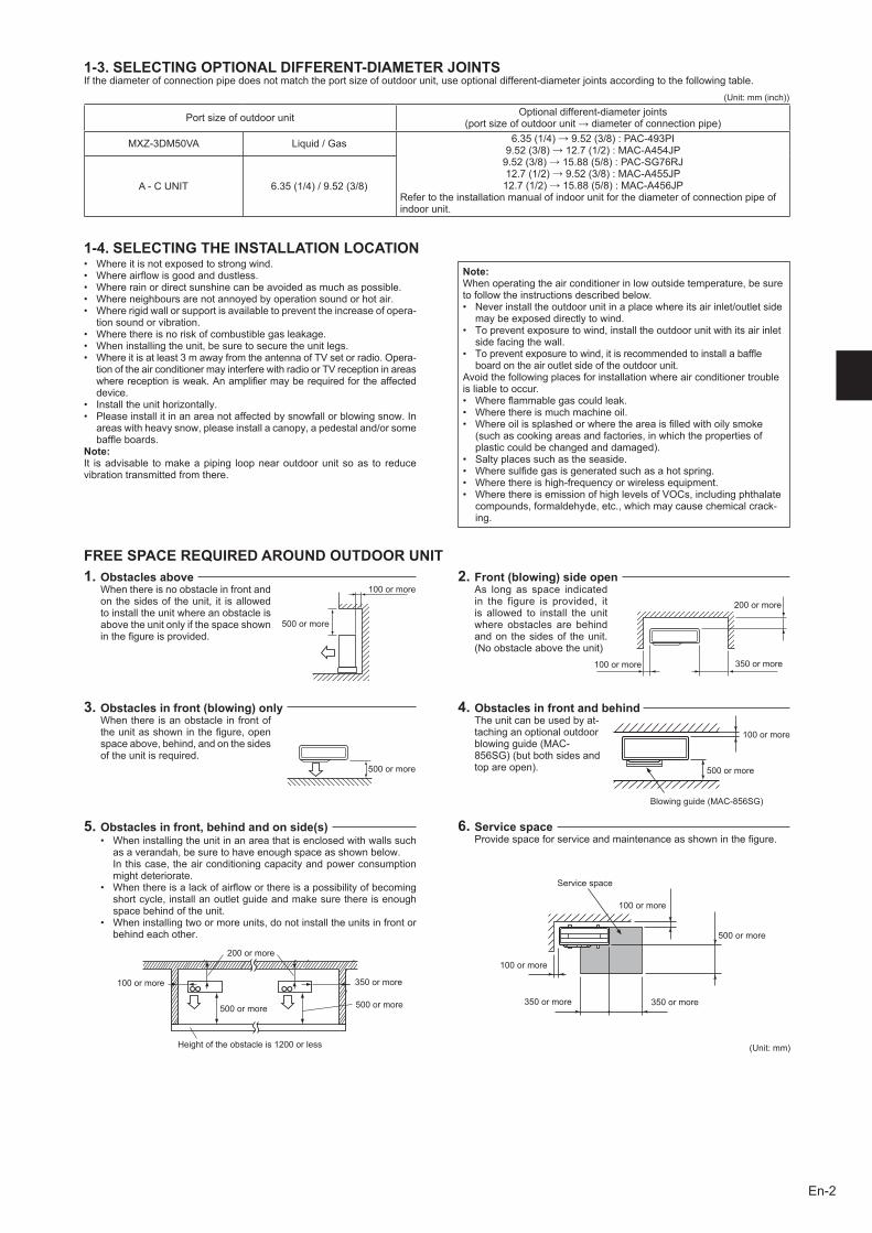
3. Obstacles in front (blowing) onlyWhenthereisanobstacleinfrontoftheunitasshowninthefigure,openspaceabove,behind,andonthesidesoftheunitisrequired.
2. Front (blowing) side openAs long as space indicatedin the figure is provided, itis allowed to install the unitwhere obstacles are behindandon thesidesof theunit.(Noobstacleabovetheunit)
1-3. SELECTING OPTIONAL DIFFERENT-DIAMETER JOINTSIfthediameterofconnectionpipedoesnotmatchtheportsizeofoutdoorunit,useoptionaldifferent-diameterjointsaccordingtothefollowingtable.
Portsizeofoutdoorunit Optionaldifferent-diameterjoints(portsizeofoutdoorunit→diameterofconnectionpipe)
MXZ-3DM50VA Liquid/Gas 6.35(1/4)→9.52(3/8):PAC-493PI9.52(3/8)→12.7(1/2):MAC-A454JP9.52(3/8)→15.88(5/8):PAC-SG76RJ12.7(1/2)→9.52(3/8):MAC-A455JP12.7(1/2)→15.88(5/8):MAC-A456JP
Refertotheinstallationmanualofindoorunitforthediameterofconnectionpipeofindoorunit.
A-CUNIT 6.35(1/4)/9.52(3/8)
FREE SPACE REQUIRED AROUND OUTDOOR UNIT
1-4. SELECTING THE INSTALLATION LOCATION• Whereitisnotexposedtostrongwind.• Whereairflowisgoodanddustless.• Whererainordirectsunshinecanbeavoidedasmuchaspossible.• Whereneighboursarenotannoyedbyoperationsoundorhotair.• Whererigidwallorsupportisavailabletopreventtheincreaseofopera-
tionsoundorvibration.• Wherethereisnoriskofcombustiblegasleakage.• Wheninstallingtheunit,besuretosecuretheunitlegs.• Whereitisatleast3mawayfromtheantennaofTVsetorradio.Opera-
tionoftheairconditionermayinterferewithradioorTVreceptioninareaswherereceptionisweak.Anamplifiermayberequiredfortheaffecteddevice.
• Installtheunithorizontally.• Pleaseinstallitinanareanotaffectedbysnowfallorblowingsnow.In
areaswithheavysnow,pleaseinstallacanopy,apedestaland/orsomebaffleboards.
Note:It isadvisable tomakeapiping loopnearoutdoorunitsoas to reducevibrationtransmittedfromthere.
Note: Whenoperatingtheairconditionerinlowoutsidetemperature,besuretofollowtheinstructionsdescribedbelow.• Neverinstalltheoutdoorunitinaplacewhereitsairinlet/outletside
maybeexposeddirectlytowind.• Topreventexposuretowind,installtheoutdoorunitwithitsairinlet
sidefacingthewall.• Topreventexposuretowind,itisrecommendedtoinstallabaffle
boardontheairoutletsideoftheoutdoorunit.Avoidthefollowingplacesforinstallationwhereairconditionertroubleisliabletooccur.• Whereflammablegascouldleak.• Wherethereismuchmachineoil.• Whereoilissplashedorwheretheareaisfilledwithoilysmoke
(suchascookingareasandfactories,inwhichthepropertiesofplasticcouldbechangedanddamaged).
• Saltyplacessuchastheseaside.• Wheresulfidegasisgeneratedsuchasahotspring.• Wherethereishigh-frequencyorwirelessequipment.• WherethereisemissionofhighlevelsofVOCs,includingphthalate
compounds,formaldehyde,etc.,whichmaycausechemicalcrack-ing.
500ormore
200ormore
350ormore100ormore
1. Obstacles aboveWhenthereisnoobstacleinfrontandon thesidesof theunit, it isallowedtoinstalltheunitwhereanobstacleisabovetheunitonlyifthespaceshowninthefigureisprovided.
100ormore
500ormore
100ormore
Servicespace
350ormore350ormore
6. Service spaceProvidespaceforserviceandmaintenanceasshowninthefigure.
500ormore
100ormore
(Unit:mm(inch))
• Wheninstallingtheunitinanareathatisenclosedwithwallssuchasaverandah,besuretohaveenoughspaceasshownbelow.
Inthiscase,theairconditioningcapacityandpowerconsumptionmightdeteriorate.
• Whenthereisalackofairfloworthereisapossibilityofbecomingshortcycle,installanoutletguideandmakesurethereisenoughspacebehindoftheunit.
• Wheninstallingtwoormoreunits,donotinstalltheunitsinfrontorbehindeachother.
5. Obstacles in front, behind and on side(s)
4. Obstacles in front and behindTheunitcanbeusedbyat-tachinganoptionaloutdoorblowingguide(MAC-856SG)(butbothsidesandtopareopen).
100ormore
500ormore
Blowingguide(MAC-856SG)
200ormore
100ormore 350ormore
500ormore 500ormore
(Unit:mm)Heightoftheobstacleis1200orless
BH79A246H01_en.indd 2 10/16/2015 9:22:41 AM
En-3
*2*2
*2
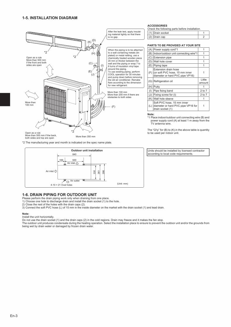
Aftertheleaktest,applyinsulat-ingmaterialtightlysothatthereisnogap.
Whenthepipingistobeattachedtoawallcontainingmetals(tinplated)ormetalnetting,useachemicallytreatedwoodenpiece20mmorthickerbetweenthewallandthepipingorwrap7to8turnsofinsulationvinyltapearoundthepiping.Touseexistingpiping,performCOOLoperationfor30minutesandpumpdownbeforeremovingtheoldairconditioner.Remakeflareaccordingtothedimensionfornewrefrigerant.
Morethan100mm
OpenasaruleMorethan500mmifthefrontandbothsidesareopen
Morethan100mmMorethan200mmifthereareobstaclestobothsides
OpenasaruleMorethan500mmiftheback,bothsidesandtopareopen Morethan350mm
1-5. INSTALLATION DIAGRAM
ACCESSORIESCheckthefollowingpartsbeforeinstallation.(1) Drainsocket 1(2) Draincap 2
PARTS TO BE PROVIDED AT YOUR SITE(A) Powersupplycord*1 1(B) Indoor/outdoorunitconnectingwire*1 1(C) Extensionpipe 1(D) Wallholecover 1(E) Pipingtape 1
(F)Extensiondrainhose(orsoftPVChose,15mminnerdiameterorhardPVCpipeVP16)
1
(G) Refrigerationoil Littleamount
(H) Putty 1(I) Pipefixingband 2to7(J) Fixingscrewfor(I) 2to7(K) Wallholesleeve 1
(L)SoftPVChose,15mminnerdiameterorhardPVCpipeVP16fordrainsocket(1)
1
Note:*1 Placeindoor/outdoorunitconnectingwire(B)and
powersupplycord(A)atleast1mawayfromtheTVantennawire.
The“Q’ty”for(B)to(K)intheabovetableisquantitytobeusedperindoorunit.
Unitsshouldbeinstalledbylicensedcontractoraccordingtolocalcoderequirements.
Outdoor unit installation
Airinlet
169 500Airinlet
4-10×21Ovalholes
396
Airoutlet
840
(Unit:mm)
361
330
1-6. DRAIN PIPING FOR OUTDOOR UNITPleaseperformthedrainpipingworkonlywhendrainingfromoneplace.1)Chooseoneholetodischargedrainandinstallthedrainsocket(1)tothehole.2)Closetherestoftheholeswiththedraincaps(2).3)ConnectthesoftPVChose(L)of15mmintheinsidediameteronthemarketwiththedrainsocket(1)andleaddrain.
Note:Installtheunithorizontally.Donotusethedrainsocket(1)andthedraincaps(2)inthecoldregions.Drainmayfreezeanditmakesthefanstop.Theoutdoorunitproducescondensateduringtheheatingoperation.Selecttheinstallationplacetoensuretopreventtheoutdoorunitand/orthegroundsfrombeingwetbydrainwaterordamagedbyfrozendrainwater.
*2Themanufacturingyearandmonthisindicatedonthespecnameplate.
BH79A246H01_en.indd 3 10/16/2015 9:22:41 AM
En-4
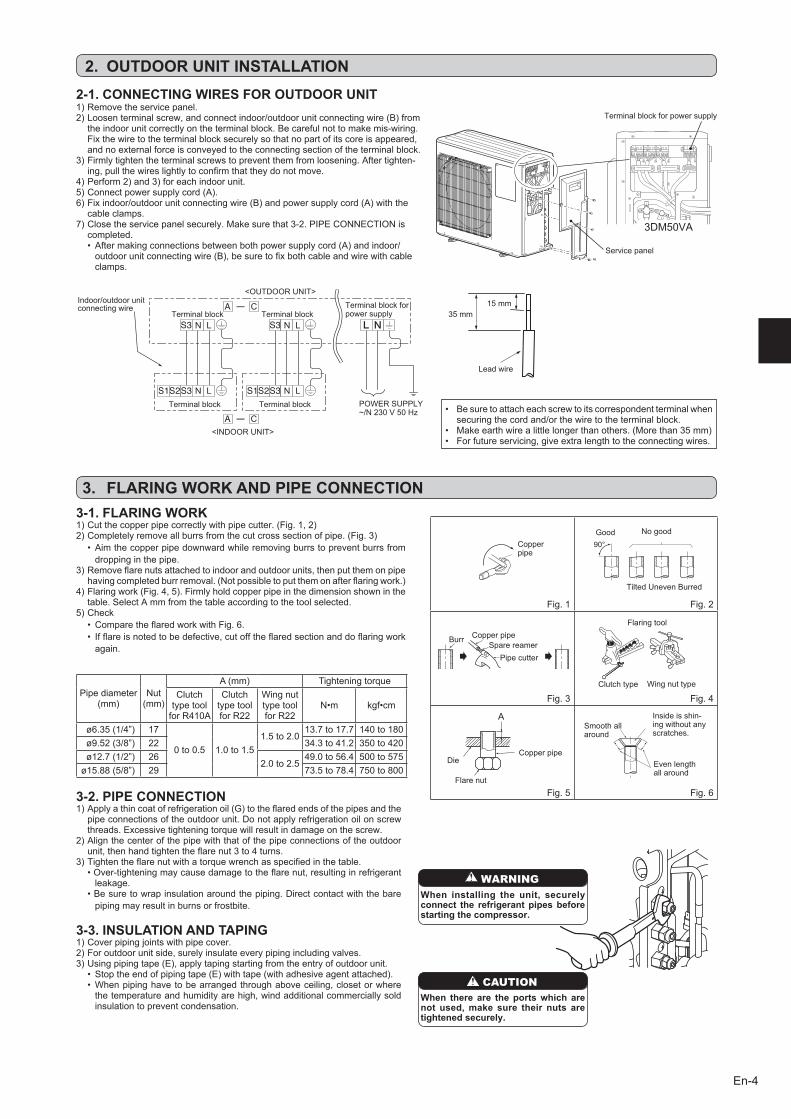
3DM50VA
35mm15mm
Leadwire
• Besuretoattacheachscrewtoitscorrespondentterminalwhensecuringthecordand/orthewiretotheterminalblock.
• Makeearthwirealittlelongerthanothers.(Morethan35mm)• Forfutureservicing,giveextralengthtotheconnectingwires.
LN
LN
LN
LN
<OUTDOORUNIT>Indoor/outdoorunitconnectingwire
<INDOORUNIT>
Terminalblock
POWERSUPPLY~/N230V50Hz
Terminalblock Terminalblock
TerminalblockforpowersupplyTerminalblock
2. OUTDOOR UNIT INSTALLATION2-1. CONNECTING WIRES FOR OUTDOOR UNIT1)Removetheservicepanel.2)Loosenterminalscrew,andconnectindoor/outdoorunitconnectingwire(B)from
theindoorunitcorrectlyontheterminalblock.Becarefulnottomakemis-wiring.Fixthewiretotheterminalblocksecurelysothatnopartofitscoreisappeared,andnoexternalforceisconveyedtotheconnectingsectionoftheterminalblock.
3)Firmlytightentheterminalscrewstopreventthemfromloosening.Aftertighten-ing,pullthewireslightlytoconfirmthattheydonotmove.
4)Perform2)and3)foreachindoorunit.5)Connectpowersupplycord(A).6)Fixindoor/outdoorunitconnectingwire(B)andpowersupplycord(A)withthe
cableclamps.7)Closetheservicepanelsecurely.Makesurethat3-2.PIPECONNECTIONis
completed.• Aftermakingconnectionsbetweenbothpowersupplycord(A)andindoor/outdoorunitconnectingwire(B),besuretofixbothcableandwirewithcableclamps.
Terminalblockforpowersupply
Servicepanel
Fig.1 Fig.2
Fig.3 Fig.4
Fig.5 Fig.6
3. FLARING WORK AND PIPE CONNECTION3-1. FLARING WORK
Pipediameter(mm)
Nut(mm)
A(mm) TighteningtorqueClutchtypetoolforR410A
ClutchtypetoolforR22
WingnuttypetoolforR22
N•m kgf•cm
ø6.35(1/4”) 17
0to0.5 1.0to1.51.5to2.0
13.7to17.7 140to180ø9.52(3/8”) 22 34.3to41.2 350to420ø12.7(1/2”) 26
2.0to2.549.0to56.4 500to575
ø15.88(5/8”) 29 73.5to78.4 750to800
TiltedUnevenBurred
Good Nogood
Burr CopperpipeSparereamer
Pipecutter
Smoothallaround
Evenlengthallaround
Insideisshin-ingwithoutanyscratches.
Flarenut
DieCopperpipe
Clutchtype
Flaringtool
Wingnuttype
3-2. PIPE CONNECTION1)Applyathincoatofrefrigerationoil(G)totheflaredendsofthepipesandthe
pipeconnectionsoftheoutdoorunit.Donotapplyrefrigerationoilonscrewthreads.Excessivetighteningtorquewillresultindamageonthescrew.
2)Alignthecenterofthepipewiththatofthepipeconnectionsoftheoutdoorunit,thenhandtightentheflarenut3to4turns.
3)Tightentheflarenutwithatorquewrenchasspecifiedinthetable.•Over-tighteningmaycausedamagetotheflarenut,resultinginrefrigerantleakage.
•Besuretowrapinsulationaroundthepiping.Directcontactwiththebarepipingmayresultinburnsorfrostbite.
3-3. INSULATION AND TAPING1)Coverpipingjointswithpipecover.2)Foroutdoorunitside,surelyinsulateeverypipingincludingvalves.3)Usingpipingtape(E),applytapingstartingfromtheentryofoutdoorunit.
• Stoptheendofpipingtape(E)withtape(withadhesiveagentattached).•Whenpipinghavetobearrangedthroughaboveceiling,closetorwherethetemperatureandhumidityarehigh,windadditionalcommerciallysoldinsulationtopreventcondensation.
Copperpipe
1)Cutthecopperpipecorrectlywithpipecutter.(Fig.1,2)2)Completelyremoveallburrsfromthecutcrosssectionofpipe.(Fig.3)
• Aimthecopperpipedownwardwhileremovingburrstopreventburrsfromdroppinginthepipe.
3)Removeflarenutsattachedtoindoorandoutdoorunits,thenputthemonpipehavingcompletedburrremoval.(Notpossibletoputthemonafterflaringwork.)
4)Flaringwork(Fig.4,5).Firmlyholdcopperpipeinthedimensionshowninthetable.SelectAmmfromthetableaccordingtothetoolselected.
5)Check• ComparetheflaredworkwithFig.6.• Ifflareisnotedtobedefective,cutofftheflaredsectionanddoflaringworkagain.
WARNINGWhen installing the unit, securely connect the refrigerant pipes before starting the compressor.
CAUTIONWhen there are the ports which are not used, make sure their nuts are tightened securely.
BH79A246H01_en.indd 4 10/16/2015 9:22:42 AM
En-5
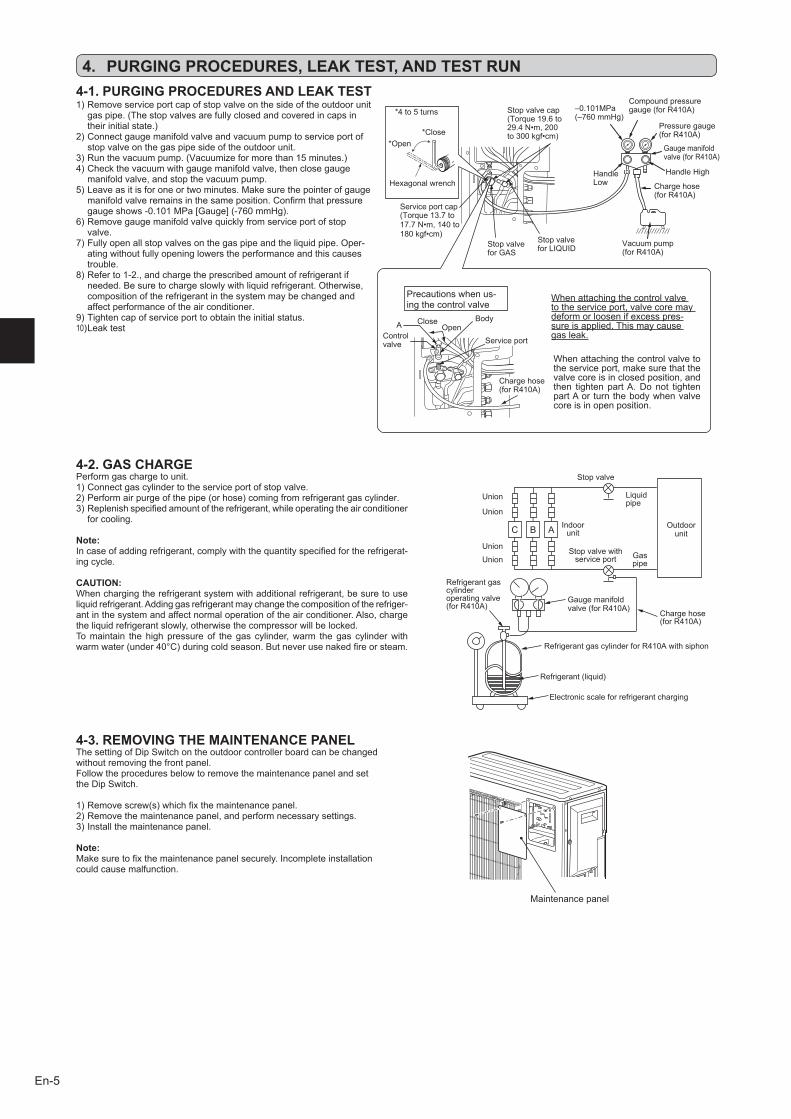
4-1. PURGING PROCEDURES AND LEAK TEST
4. PURGING PROCEDURES, LEAK TEST, AND TEST RUN
4-2. GAS CHARGEPerformgaschargetounit.1)Connectgascylindertotheserviceportofstopvalve.2)Performairpurgeofthepipe(orhose)comingfromrefrigerantgascylinder.3)Replenishspecifiedamountoftherefrigerant,whileoperatingtheairconditioner
forcooling.
Note:Incaseofaddingrefrigerant,complywiththequantityspecifiedfortherefrigerat-ingcycle.
CAUTION:Whenchargingtherefrigerantsystemwithadditionalrefrigerant,besuretouseliquidrefrigerant.Addinggasrefrigerantmaychangethecompositionoftherefriger-antinthesystemandaffectnormaloperationoftheairconditioner.Also,chargetheliquidrefrigerantslowly,otherwisethecompressorwillbelocked.Tomaintain thehighpressureof thegas cylinder,warm thegas cylinderwithwarmwater(under40°C)duringcoldseason.Butneverusenakedfireorsteam.
1)Removeserviceportcapofstopvalveonthesideoftheoutdoorunitgaspipe.(Thestopvalvesarefullyclosedandcoveredincapsintheirinitialstate.)
2)Connectgaugemanifoldvalveandvacuumpumptoserviceportofstopvalveonthegaspipesideoftheoutdoorunit.
3)Runthevacuumpump.(Vacuumizeformorethan15minutes.)4)Checkthevacuumwithgaugemanifoldvalve,thenclosegauge
manifoldvalve,andstopthevacuumpump.5)Leaveasitisforoneortwominutes.Makesurethepointerofgauge
manifoldvalveremainsinthesameposition.Confirmthatpressuregaugeshows-0.101MPa[Gauge](-760mmHg).
6)Removegaugemanifoldvalvequicklyfromserviceportofstopvalve.
7)Fullyopenallstopvalvesonthegaspipeandtheliquidpipe.Oper-atingwithoutfullyopeninglowerstheperformanceandthiscausestrouble.
8)Referto1-2.,andchargetheprescribedamountofrefrigerantifneeded.Besuretochargeslowlywithliquidrefrigerant.Otherwise,compositionoftherefrigerantinthesystemmaybechangedandaffectperformanceoftheairconditioner.
9)Tightencapofserviceporttoobtaintheinitialstatus.10)Leaktest
Union
Stopvalve
Liquidpipe
Indoorunit
Stopvalvewithserviceport Gas
pipe
Refrigerantgascylinderoperatingvalve(forR410A)
Gaugemanifoldvalve(forR410A) Chargehose
(forR410A)
RefrigerantgascylinderforR410Awithsiphon
Electronicscaleforrefrigerantcharging
Refrigerant(liquid)
Outdoorunit
Union
Union
Union
StopvalveforGAS
Stopvalvecap(Torque19.6to29.4N•m,200to300kgf•cm)
Gaugemanifoldvalve(forR410A)
Compoundpressuregauge(forR410A)–0.101MPa
(–760mmHg)
HandleLow
HandleHigh
Vacuumpump(forR410A)
*Close*Open
Hexagonalwrench
*4to5turns
StopvalveforLIQUID
Pressuregauge(forR410A)
Precautionswhenus-ingthecontrolvalve
Whenattachingthecontrolvalvetotheserviceport,valvecoremaydeformorloosenifexcesspres-sureisapplied.Thismaycausegasleak.Serviceport
Chargehose(forR410A)
BodyCloseOpen
Controlvalve
A
Whenattachingthecontrolvalvetotheserviceport,makesurethatthevalvecoreisinclosedposition,andthen tightenpartA.Donot tightenpartAor turnthebodywhenvalvecoreisinopenposition.
Serviceportcap(Torque13.7to17.7N•m,140to180kgf•cm)
Chargehose(forR410A)
4-3. REMOVING THE MAINTENANCE PANELThesettingofDipSwitchontheoutdoorcontrollerboardcanbechangedwithoutremovingthefrontpanel.FollowtheproceduresbelowtoremovethemaintenancepanelandsettheDipSwitch.
1)Removescrew(s)whichfixthemaintenancepanel.2)Removethemaintenancepanel,andperformnecessarysettings.3)Installthemaintenancepanel.
Note:Makesuretofixthemaintenancepanelsecurely.Incompleteinstallationcouldcausemalfunction.
Maintenancepanel
BH79A246H01_en.indd 5 10/16/2015 9:22:42 AM
En-6
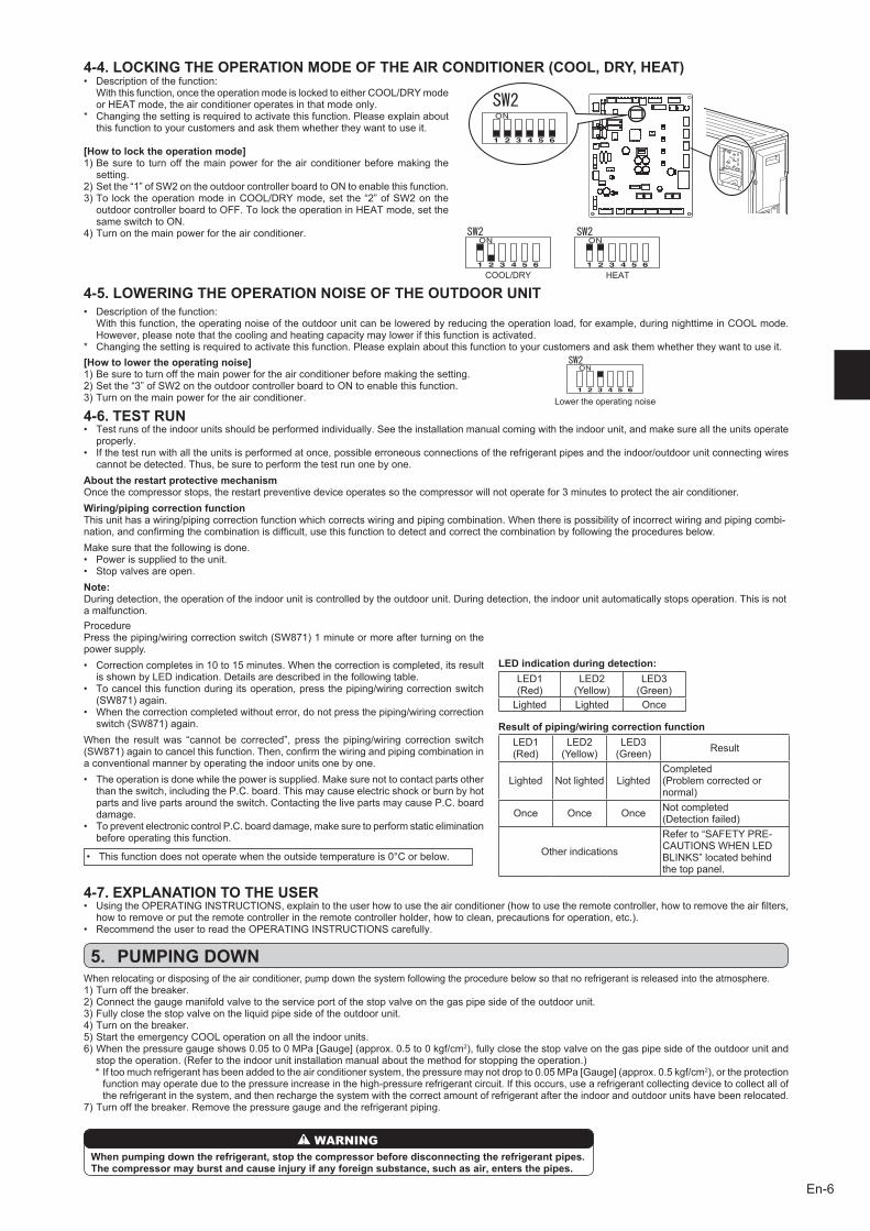
4-4. LOCKING THE OPERATION MODE OF THE AIR CONDITIONER (COOL, DRY, HEAT)
4-5. LOWERING THE OPERATION NOISE OF THE OUTDOOR UNIT
• Descriptionofthefunction: Withthisfunction,oncetheoperationmodeislockedtoeitherCOOL/DRYmode
orHEATmode,theairconditioneroperatesinthatmodeonly.* Changingthesettingisrequiredtoactivatethisfunction.Pleaseexplainabout
thisfunctiontoyourcustomersandaskthemwhethertheywanttouseit.
[How to lock the operation mode]1)Besure to turnoff themainpower for theairconditionerbeforemaking the
setting.2)Setthe“1”ofSW2ontheoutdoorcontrollerboardtoONtoenablethisfunction.3)TolocktheoperationmodeinCOOL/DRYmode,set the“2”ofSW2onthe
outdoorcontrollerboardtoOFF.TolocktheoperationinHEATmode,setthesameswitchtoON.
4)Turnonthemainpowerfortheairconditioner.
• Descriptionofthefunction: Withthisfunction,theoperatingnoiseoftheoutdoorunitcanbeloweredbyreducingtheoperationload,forexample,duringnighttimeinCOOLmode.
However,pleasenotethatthecoolingandheatingcapacitymaylowerifthisfunctionisactivated.* Changingthesettingisrequiredtoactivatethisfunction.Pleaseexplainaboutthisfunctiontoyourcustomersandaskthemwhethertheywanttouseit.
Lowertheoperatingnoise
[How to lower the operating noise]1)Besuretoturnoffthemainpowerfortheairconditionerbeforemakingthesetting.2)Setthe“3”ofSW2ontheoutdoorcontrollerboardtoONtoenablethisfunction.3)Turnonthemainpowerfortheairconditioner.
4-6. TEST RUN• Testrunsoftheindoorunitsshouldbeperformedindividually.Seetheinstallationmanualcomingwiththeindoorunit,andmakesurealltheunitsoperate
properly.• Ifthetestrunwithalltheunitsisperformedatonce,possibleerroneousconnectionsoftherefrigerantpipesandtheindoor/outdoorunitconnectingwires
cannotbedetected.Thus,besuretoperformthetestrunonebyone.About the restart protective mechanismOncethecompressorstops,therestartpreventivedeviceoperatessothecompressorwillnotoperatefor3minutestoprotecttheairconditioner.Wiring/piping correction functionThisunithasawiring/pipingcorrectionfunctionwhichcorrectswiringandpipingcombination.Whenthereispossibilityofincorrectwiringandpipingcombi-nation,andconfirmingthecombinationisdifficult,usethisfunctiontodetectandcorrectthecombinationbyfollowingtheproceduresbelow.Makesurethatthefollowingisdone.• Powerissuppliedtotheunit.• Stopvalvesareopen.Note:Duringdetection,theoperationoftheindoorunitiscontrolledbytheoutdoorunit.Duringdetection,theindoorunitautomaticallystopsoperation.Thisisnotamalfunction.
5. PUMPING DOWNWhenrelocatingordisposingoftheairconditioner,pumpdownthesystemfollowingtheprocedurebelowsothatnorefrigerantisreleasedintotheatmosphere.1)Turnoffthebreaker.2)Connectthegaugemanifoldvalvetotheserviceportofthestopvalveonthegaspipesideoftheoutdoorunit.3)Fullyclosethestopvalveontheliquidpipesideoftheoutdoorunit.4)Turnonthebreaker.5)StarttheemergencyCOOLoperationonalltheindoorunits.6)Whenthepressuregaugeshows0.05to0MPa[Gauge](approx.0.5to0kgf/cm2),fullyclosethestopvalveonthegaspipesideoftheoutdoorunitand
stoptheoperation.(Refertotheindoorunitinstallationmanualaboutthemethodforstoppingtheoperation.) *Iftoomuchrefrigeranthasbeenaddedtotheairconditionersystem,thepressuremaynotdropto0.05MPa[Gauge](approx.0.5kgf/cm2),ortheprotection
functionmayoperateduetothepressureincreaseinthehigh-pressurerefrigerantcircuit.Ifthisoccurs,usearefrigerantcollectingdevicetocollectalloftherefrigerantinthesystem,andthenrechargethesystemwiththecorrectamountofrefrigerantaftertheindoorandoutdoorunitshavebeenrelocated.
7)Turnoffthebreaker.Removethepressuregaugeandtherefrigerantpiping.
When pumping down the refrigerant, stop the compressor before disconnecting the refrigerant pipes.The compressor may burst and cause injury if any foreign substance, such as air, enters the pipes.
WARNING
4-7. EXPLANATION TO THE USER• UsingtheOPERATINGINSTRUCTIONS,explaintotheuserhowtousetheairconditioner(howtousetheremotecontroller,howtoremovetheairfilters,
howtoremoveorputtheremotecontrollerintheremotecontrollerholder,howtoclean,precautionsforoperation,etc.).• RecommendtheusertoreadtheOPERATINGINSTRUCTIONScarefully.
HEATCOOL/DRY
ProcedurePressthepiping/wiringcorrectionswitch(SW871)1minuteormoreafterturningonthepowersupply.• Correctioncompletesin10to15minutes.Whenthecorrectioniscompleted,itsresult
isshownbyLEDindication.Detailsaredescribedinthefollowingtable.• Tocancelthisfunctionduringitsoperation,pressthepiping/wiringcorrectionswitch
(SW871)again.• Whenthecorrectioncompletedwithouterror,donotpressthepiping/wiringcorrection
switch(SW871)again.When the resultwas “cannot be corrected”, press the piping/wiring correction switch(SW871)againtocancelthisfunction.Then,confirmthewiringandpipingcombinationinaconventionalmannerbyoperatingtheindoorunitsonebyone.• Theoperationisdonewhilethepowerissupplied.Makesurenottocontactpartsother
thantheswitch,includingtheP.C.board.Thismaycauseelectricshockorburnbyhotpartsandlivepartsaroundtheswitch.ContactingthelivepartsmaycauseP.C.boarddamage.
• TopreventelectroniccontrolP.C.boarddamage,makesuretoperformstaticeliminationbeforeoperatingthisfunction.
• Thisfunctiondoesnotoperatewhentheoutsidetemperatureis0°Corbelow.
LED indication during detection:LED1(Red)
LED2(Yellow)
LED3(Green)
Lighted Lighted Once
Result of piping/wiring correction functionLED1(Red)
LED2(Yellow)
LED3(Green) Result
Lighted Notlighted LightedCompleted(Problemcorrectedornormal)
Once Once Once Notcompleted(Detectionfailed)
Otherindications
Referto“SAFETYPRE-CAUTIONSWHENLEDBLINKS”locatedbehindthetoppanel.
BH79A246H01_en.indd 6 10/16/2015 9:22:44 AM
BH79A246H01
HEAD OFFICE: TOKYO BLDG., 2-7-3, MARUNOUCHI, CHIYODA-KU, TOKYO 100-8310, JAPAN
EC DECLARATION OF CONFORMITYEG-KONFORMITÄTSERKLÄRUNGDÉCLARATION DE CONFORMITÉ CEEG-CONFORMITEITSVERKLARING
DECLARACIÓN DE CONFORMIDAD CEDICHIARAZIONE DI CONFORMITÀ CEΔΗΛΩΣΗΠΙΣΤΟΤΗΤΑΣΕΚDECLARAÇÃODECONFORMIDADECE
EU-OVERENSSTEMMELSESERKLÆRINGEG-DEKLARATION OM ÖVERENSSTÄMMELSEEC UYGUNLUK BEYANIДЕКЛАРАЦИЯСООТВЕТСТВИЯНОРМАМЕС
CE-ERKLÆRING OM SAMSVAR EY-VAATIMUSTENMUKAISUUSVAKUUTUSДЕКЛАРАЦИЯЗАСЪОТВЕТСТВИЕ
MITSUBISHI ELECTRIC CONSUMER PRODUCTS (THAILAND) CO., LTDAMATA NAKORN INDUSTRIAL ESTATE 700/406 MOO 7, TAMBON DON HUA ROH, AMPHUR MUANG, CHONBURI 20000, THAILAND
hereby declares under its sole responsibility that the air conditioners and heat pumps described below for use in residential, commercial and light-industrial environments:erklärt hiermit auf seine alleinige Verantwortung, dass die Klimaanlagen und Wärmepumpen für das häusliche, kommerzielle und leicht-industrielle Umfeld wie unten beschrieben:déclare par la présente et sous sa propre responsabilité que les climatiseurs et les pompes à chaleur décrits ci-dessous, destinés à un usage dans des environnements résidentiels, commerciaux et d’industrie légère :verklaart hierbij onder eigen verantwoordelijkheid dat de voor residentiële, commerciële en licht-industriële omgevingen bestemde airconditioners en warmtepompen zoals onderstaand beschreven:por la presente declara bajo su única responsabilidad que los acondicionadores de aire y bombas de calor descritas a continuación para su uso en entornos residenciales, comerciales y de industria ligera:conferma con la presente, sotto la sua esclusiva responsabilità, che i condizionatori d’aria e le pompe di calore descritti di seguito e destinati all’utilizzo in ambienti residenziali, commer-ciali e semi-industriali:μετοπαρόνπιστοποιείμεαποκλειστικήτηςευθύνηότιοιτακλιματιστικάκαιοιαντλίεςθέρμανσηςπουπεριγράφονταιπαρακάτωγιαχρήσησεοικιακό,επαγγελματικόκαιελαφριάςβιομηχανίαςπεριβάλλοντα:através da presente declara sob sua única responsabilidade que os aparelhos de ar condicionado e bombas de calor abaixo descritos para uso residencial, comercial e de indústria ligeira:erklærer hermed under eneansvar, at de herunder beskrevne airconditionanlæg og varmepumper til brug i privat boligbyggeri, erhvervsområder og inden for let industri:intygar härmed att luftkonditioneringarna och värmepumparna som beskrivs nedan för användning i bostäder, kommersiella miljöer och lätta industriella miljöer:ev,ticaretvehafifsanayiortamlarındakullanımamaçlıüretilenveaşağıdaaçıklananklimaveısıtmapompalarıylailgiliaşağıdakihususlarıyalnızcakendisorumluluğundabeyaneder:настоящимзаявляетиберетнасебяисключительнуюответственностьзато,чтокондиционерыитепловыенасосы,описанныенижеипредназначенныедляэксплуатациивжилыхпомещениях,торговыхзалахинапредприятияхлегкойпромышленности:erklærer et fullstendig ansvar for undernevnte klimaanlegg og varmepumper ved bruk i boliger, samt kommersielle og lettindustrielle miljøer: vakuuttaa täten yksinomaisella vastuullaan, että jäljempänä kuvatut asuinrakennuksiin, pienteollisuuskäyttöön ja kaupalliseen käyttöön tarkoitetut ilmastointilaitteet ja lämpöpumput:деклариранасвоясобственаотговорност,чеклиматицитеитермопомпите,описанипо-долу,заупотребавжилищни,търговскиилекипромишлениусловия:
Note: Its serial number is on the nameplate of the product.Hinweis:DieSeriennummerbefindetsichaufdemKennschilddesProdukts.Remarque : Le numéro de série de l’appareil se trouve sur la plaque du produit.Opmerking: het serienummer staat op het naamplaatje van het product.Nota: El número de serie se encuentra en la placa que contiene el nombre del producto.Nota: il numero di serie si trova sulla targhetta del prodotto.Σημείωση:Οσειριακόςτουαριθμόςβρίσκεταιστηνπινακίδαονόματοςτουπροϊόντος.Nota: o número de série encontra-se na placa que contém o nome do produto.
Bemærk: Serienummeret står på produktets fabriksskilt.Obs:Serienumretfinnspåproduktensnamnplåt.Not:Serinumarasıürününisimplakasındayeralır.Примечание:серийныйномеруказаннапаспортноетабличкеизделия.Merk:Serienummeretbefinnersegpånavneplatentilproduktet.Huomautus: Sarjanumero on merkitty laitteen arvokilpeen.Забележка:Серийниятмуномеренатабелкатанапродукта.
DirectivesRichtlinienDirectivesRichtlijnenDirectivasDirettiveΟδηγίεςDirectivas
DirektiverDirektivDirektiflerДирективыDirektiver DirektiivitДирективи
OurauthorizedrepresentativeinEU,whoisauthorizedtocompilethetechnicalfile,isasfollows.Unser autorisierter Vertreter in der EU, der ermächtigt ist die technischen Daten zu kompilieren, ist wie folgt.NotrereprésentantagrééedansL’UE,quiestautoriséàcompilerlefichiertechnique,estlesuivant.Onze geautoriseerde vertegenwoordiger in de EU, die gemachtigd is het technische bestand te com-pileren, is als volgt.Nuestro representante autorizado en la UE, que está autorizado para compilar el archivo técnico, es el siguiente.Il nostro rivenditore autorizzato nell’UE, responsabile della stesura della scheda tecnica, è il seguente.ΟεξουσιοδοτημένοςαντιπρόσωπόςμαςστηνΕΕ,οοποίοςείναιεξουσιοδοτημένοςνασυντάξειτοντεχνικόφάκελο,είναιοεξής.OnossorepresentanteautorizadonaUE,queestáautorizadoparacompilaroficheirotécnico,éoseguinte:
VoresautoriserederepræsentantiEU,somerautoriserettiludarbejdelseafdentekniskefil,erføl-gende.VårEG-representantsomärauktoriseradattsammanställadentekniskafilenärföljande.AvrupaBirliği’ndebulunanve teknikdosyayıdüzenlemeyetkisinesahipyetkili temsilcimizaşağıdabelirtilmiştir:НашавторизованныйпредставительвЕС,уполномоченныйнасоставлениетехническогофай-ла,указанниже.VårautoriserteEU-representant, somharautorisasjon til åutarbeidedenne tekniskefilen, er somfølger.Valtuutettu EU-edustaja, joka on valtuutettu laatimaan teknisen eritelmän, on mainittu alla.НашупълномощенпредставителвЕС,койтоеупълномощендасъставитехническотодосие,екактоследва.
MITSUBISHI ELECTRIC EUROPE, B.V.HARMAN HOUSE, 1 GEORGE STREET, UXBRIDGE, MIDDLESEX UB8 1QQ, U.K.Masahiko KONISHIProduct Marketing Director
Issued: 27 November, 2015 Tomoyuki MIWATHAILAND Manager, Quality Assurance Department
MITSUBISHI ELECTRIC, MXZ-3DM50VA
2006/95/EC: Low Voltage Directive2006/42/EC: Machinery Directive2004/108/EC: Electromagnetic Compatibility Directive2009/125/EC: Energy-related Products Directive and Regulation (EU) No 206/2012
BH79A246H01_cover.indd 2 10/16/2015 9:22:16 AM