Speed Control of DC Motors: the speed of a motor is given by the ...
17
64 Speed Control of DC Motors: the speed of a motor is given by the relation a a a a R I V K p A Z R I V N 60 where R a = armature circuit resistance. It is obvious that the speed can be controlled by varying (i) Flux/pole, Φ (Flux Control) (ii) Resistance R a of armature circuit (Rheostatic Control) and (iii) Applied voltage V (Voltage Control). Speed Control of Shunt motor: (i) Variation of Flux or Flux Control Method: By decreasing the flux, the speed can be increased and vice versa. The flux of a dc motor can be changed by changing I sh with help of a shunt field rheostat. Since I sh is relatively small, shunt field rheostat has to carry only a small current, which means I 2 sh R loss is small, so that rheostat is small in size. (ii) Armature or Rheostatic Control Method: This method is used when speeds below the no-load speed are required. As the supply voltage is normally constant, the voltage across the armature is varied by inserting a variable rheostat in series with the armature circuit. As controller resistance is increased, voltage across the armature is decreased, thereby decreasing the armature speed. For a load constant torque, speed is approximately proportional to the voltage across the armature. From the
Transcript of Speed Control of DC Motors: the speed of a motor is given by the ...
64
Speed Control of DC Motors: the speed of a motor is given by the
relation
aaaa RIVK
pA
ZRIVN
60 where Ra= armature circuit resistance. It is
obvious that the speed can be controlled by varying
(i) Flux/pole, Φ (Flux Control)
(ii) Resistance Ra of armature circuit (Rheostatic Control) and
(iii) Applied voltage V (Voltage Control).
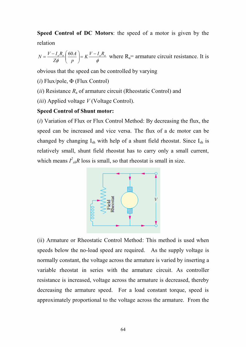
Speed Control of Shunt motor:
(i) Variation of Flux or Flux Control Method: By decreasing the flux, the
speed can be increased and vice versa. The flux of a dc motor can be
changed by changing Ish with help of a shunt field rheostat. Since Ish is
relatively small, shunt field rheostat has to carry only a small current,
which means I2shR loss is small, so that rheostat is small in size.
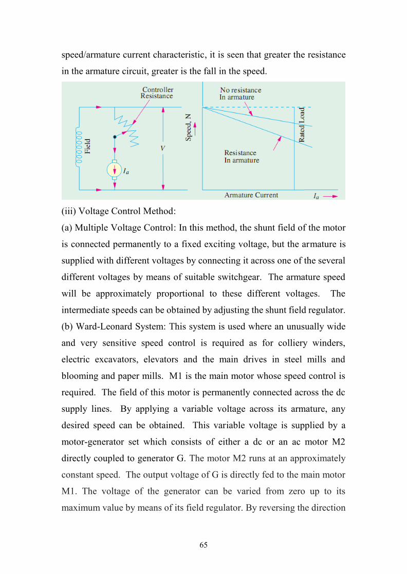
(ii) Armature or Rheostatic Control Method: This method is used when
speeds below the no-load speed are required. As the supply voltage is
normally constant, the voltage across the armature is varied by inserting a
variable rheostat in series with the armature circuit. As controller
resistance is increased, voltage across the armature is decreased, thereby
decreasing the armature speed. For a load constant torque, speed is
approximately proportional to the voltage across the armature. From the
65
speed/armature current characteristic, it is seen that greater the resistance
in the armature circuit, greater is the fall in the speed.
(iii) Voltage Control Method:
(a) Multiple Voltage Control: In this method, the shunt field of the motor
is connected permanently to a fixed exciting voltage, but the armature is
supplied with different voltages by connecting it across one of the several
different voltages by means of suitable switchgear. The armature speed
will be approximately proportional to these different voltages. The
intermediate speeds can be obtained by adjusting the shunt field regulator.
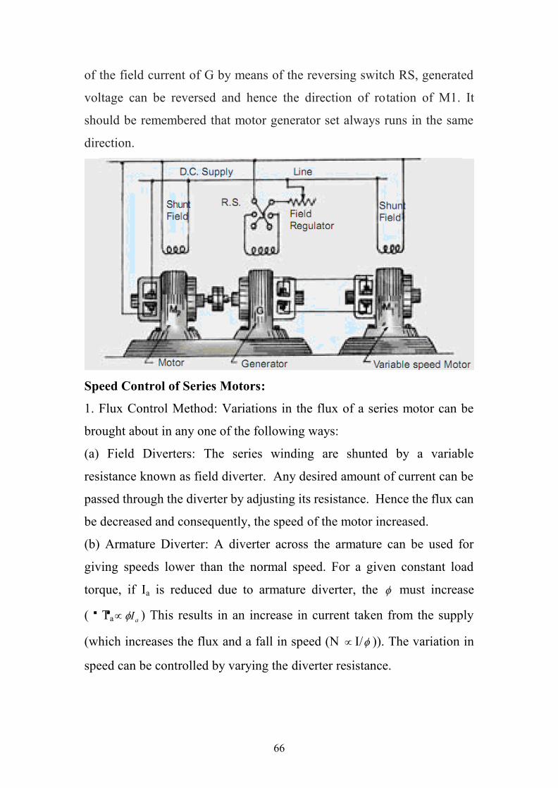
(b) Ward-Leonard System: This system is used where an unusually wide
and very sensitive speed control is required as for colliery winders,
electric excavators, elevators and the main drives in steel mills and
blooming and paper mills. M1 is the main motor whose speed control is
required. The field of this motor is permanently connected across the dc
supply lines. By applying a variable voltage across its armature, any
desired speed can be obtained. This variable voltage is supplied by a
motor-generator set which consists of either a dc or an ac motor M2
directly coupled to generator G. The motor M2 runs at an approximately
constant speed. The output voltage of G is directly fed to the main motor
M1. The voltage of the generator can be varied from zero up to its
maximum value by means of its field regulator. By reversing the direction
66
of the field current of G by means of the reversing switch RS, generated
voltage can be reversed and hence the direction of rotation of M1. It
should be remembered that motor generator set always runs in the same
direction.
Speed Control of Series Motors:
1. Flux Control Method: Variations in the flux of a series motor can be
brought about in any one of the following ways:
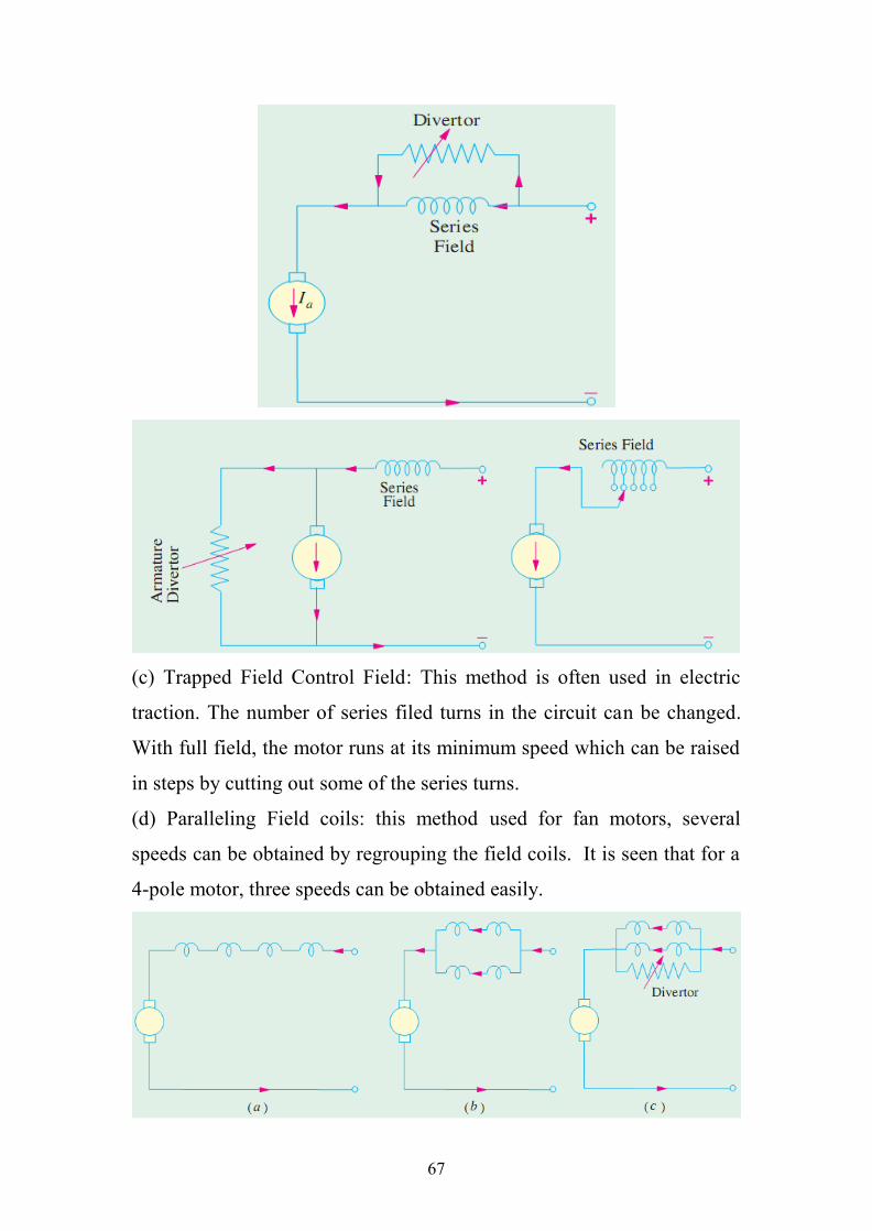
(a) Field Diverters: The series winding are shunted by a variable
resistance known as field diverter. Any desired amount of current can be
passed through the diverter by adjusting its resistance. Hence the flux can
be decreased and consequently, the speed of the motor increased.
(b) Armature Diverter: A diverter across the armature can be used for
giving speeds lower than the normal speed. For a given constant load
torque, if Ia is reduced due to armature diverter, the must increase
(∵Ta aI ) This results in an increase in current taken from the supply
(which increases the flux and a fall in speed (N I/ )). The variation in
speed can be controlled by varying the diverter resistance.
67
(c) Trapped Field Control Field: This method is often used in electric
traction. The number of series filed turns in the circuit can be changed.
With full field, the motor runs at its minimum speed which can be raised
in steps by cutting out some of the series turns.
(d) Paralleling Field coils: this method used for fan motors, several
speeds can be obtained by regrouping the field coils. It is seen that for a
4-pole motor, three speeds can be obtained easily.
68
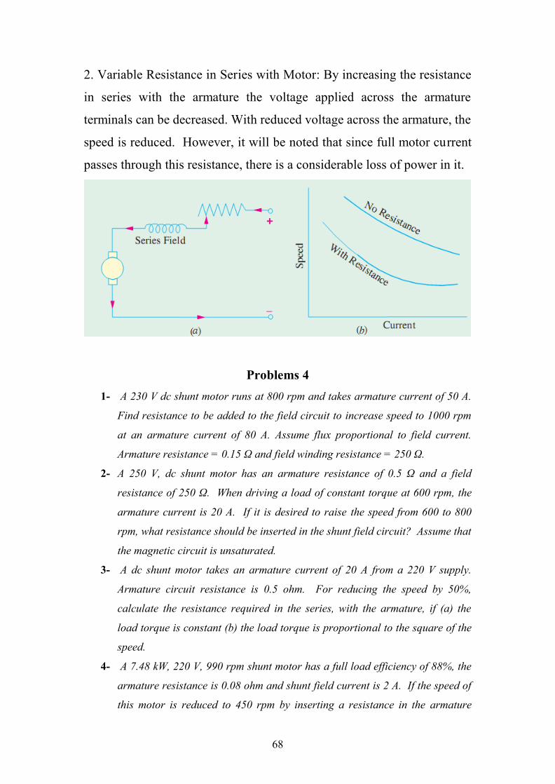
2. Variable Resistance in Series with Motor: By increasing the resistance
in series with the armature the voltage applied across the armature
terminals can be decreased. With reduced voltage across the armature, the
speed is reduced. However, it will be noted that since full motor current
passes through this resistance, there is a considerable loss of power in it.
Problems 41- A 230 V dc shunt motor runs at 800 rpm and takes armature current of 50 A.
Find resistance to be added to the field circuit to increase speed to 1000 rpm
at an armature current of 80 A. Assume flux proportional to field current.
Armature resistance = 0.15 Ω and field winding resistance = 250 Ω.
2- A 250 V, dc shunt motor has an armature resistance of 0.5 Ω and a field
resistance of 250 Ω. When driving a load of constant torque at 600 rpm, the
armature current is 20 A. If it is desired to raise the speed from 600 to 800
rpm, what resistance should be inserted in the shunt field circuit? Assume that
the magnetic circuit is unsaturated.
3- A dc shunt motor takes an armature current of 20 A from a 220 V supply.
Armature circuit resistance is 0.5 ohm. For reducing the speed by 50%,
calculate the resistance required in the series, with the armature, if (a) the
load torque is constant (b) the load torque is proportional to the square of the
speed.
4- A 7.48 kW, 220 V, 990 rpm shunt motor has a full load efficiency of 88%, the
armature resistance is 0.08 ohm and shunt field current is 2 A. If the speed of
this motor is reduced to 450 rpm by inserting a resistance in the armature
69
circuit, find the motor output, the armature current, external resistance to be
inserted in the armature circuit and overall efficiency. Assume the load torque
to remain constant.
5- A 250 V dc shunt motor has armature circuit resistance of 0.5 Ω and a field
circuit resistance of 125 Ω. It drives a load at 1000 rpm and takes 30 A. The
field circuit resistance is then slowly increased to 150 Ω. If the flux and field
current can be assumed to be proportional and if the load torque remains
constant, calculate the final speed and armature current. [1186 rpm. 33.6 A]
6- A shunt-wound motor has a field resistance of 400 Ω and an armature
resistance of 0.1 Ω and runs off 240 V supply. The armature current is 60 A
and the motor speed is 900 rpm; Assuming a straight line magnetization
curve, calculate (a) the additional resistance in the field to increase the speed
to 1000 rpm for the same armature current and (b) the speed with the original
field current of 200 A. [(a) 44.4 Ω (b) 842.5 rpm]
7- A 250-V shunt motor has an armature current of 20 A when running at 1000
rpm against full load torque. The armature resistance is 0.5 Ω. What
resistance must be inserted in series with the armature to reduce the speed to
500 rpm at the same torque and what will be the speed if the load torque is
halved with this resistance in the circuit? Assume the flux to remain constant
throughout and neglect brush contact drop.
8- A 7.46 kW, 220 V, 900 rpm shunt motor has a full-load efficiency of 88 per
cent, an armature resistance of 0.08 Ω and shunt field current of 2 A. If the
speed of this motor is reduced to 450 rpm by inserting a resistance in the
armature circuit, the load torque remaining constant, find the motor output,
the armature current, the external resistance and the overall efficiency.
9- A 200 V, dc series motor takes 40 A when running at 700 rpm. Calculate the
speed at which the motor will run and the current taken from the supply if the
field is shunted by a resistance equal to the field resistance and the load
torque is increased by 50%. Armature resistance = 0.15 Ω, field resistance =
0.1 Ω It may be assumed that flux per pole is proportional to the field.
10- A 4-pole, 250 V dc series motor takes 20 A and runs at 900 rpm each field
coil has resistance of 0.025 ohm and the resistance of the armature is 0.1 ohm.
At what speed will the motor run developing the same torque if : (i) a diverter
of 0.2 ohm is connected in parallel with the series field (ii) rearranging the
70
field coils in two series and parallel groups Assume unsaturated magnetic
operation.
11- A 200V, dc series motor runs at 500rpm when taking a line current of 25A.
The resistance of the armature is 0.2Ω and that of the series field 0.6Ω. At
what speed will it run when developing the same torque when armature
diverter of 10Ω is used? Assume a straight line magnetization curve.[314rpm]
Electric Braking: A motor and its load may be brought to rest quickly by
using either (i) Friction Braking or (ii) Electric Braking. Mechanical
brake has one drawback: it is difficult to achieve a smooth stop because
it depends on the condition of the braking surface as well as on the skill
of the operator. The excellent electric braking methods are available
which eliminate the need of brake lining levers and other mechanical
gadgets. Electric braking, both for shunt and series motors, is of the
following three types:
(i) Rheostatic or dynamic braking
(ii) Plugging i.e., reversal of torque so that armature tends to rotate
in the opposite direction.
(iii) Regenerative braking.
Obviously, friction brake is necessary for holding the motor even after it
has been brought to rest.
Electric Braking of Shunt Motors:
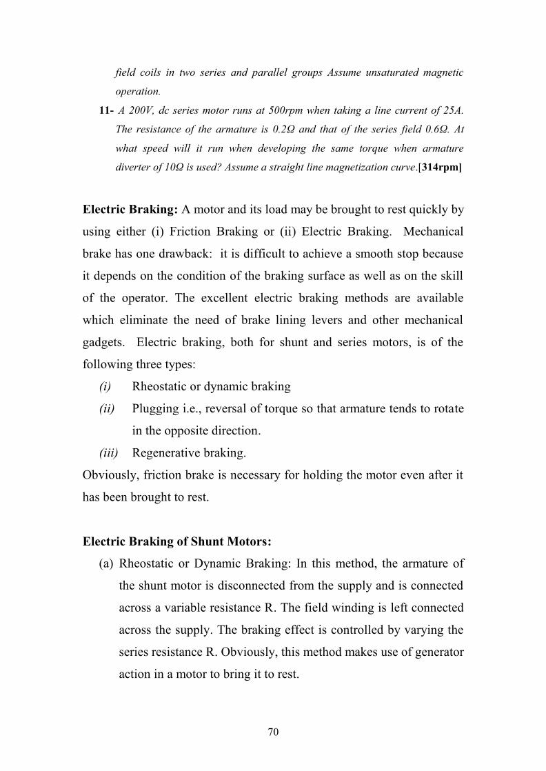
(a) Rheostatic or Dynamic Braking: In this method, the armature of
the shunt motor is disconnected from the supply and is connected
across a variable resistance R. The field winding is left connected
across the supply. The braking effect is controlled by varying the
series resistance R. Obviously, this method makes use of generator
action in a motor to bring it to rest.
71
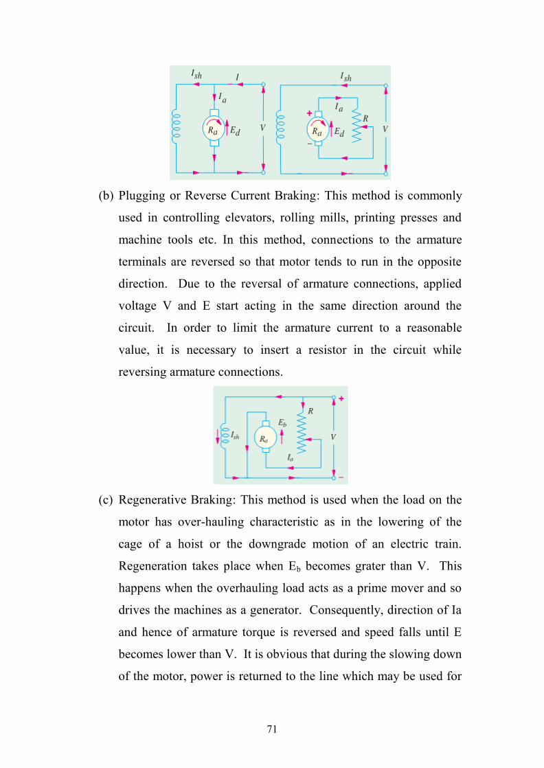
(b) Plugging or Reverse Current Braking: This method is commonly
used in controlling elevators, rolling mills, printing presses and
machine tools etc. In this method, connections to the armature
terminals are reversed so that motor tends to run in the opposite
direction. Due to the reversal of armature connections, applied
voltage V and E start acting in the same direction around the
circuit. In order to limit the armature current to a reasonable
value, it is necessary to insert a resistor in the circuit while
reversing armature connections.
(c) Regenerative Braking: This method is used when the load on the
motor has over-hauling characteristic as in the lowering of the
cage of a hoist or the downgrade motion of an electric train.
Regeneration takes place when Eb becomes grater than V. This
happens when the overhauling load acts as a prime mover and so
drives the machines as a generator. Consequently, direction of Ia
and hence of armature torque is reversed and speed falls until E
becomes lower than V. It is obvious that during the slowing down
of the motor, power is returned to the line which may be used for
72
supplying another train on an upgrade, thereby relieving the
powerhouse of part of its load.
Electric Braking of Series Motor:
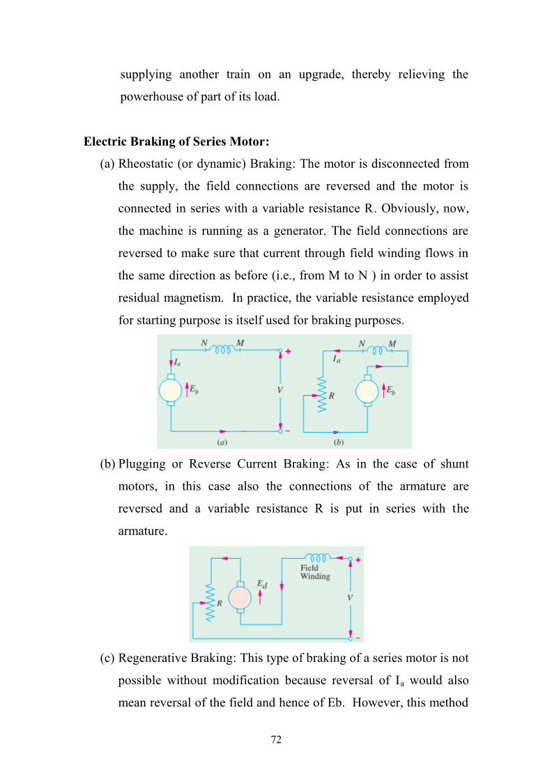
(a) Rheostatic (or dynamic) Braking: The motor is disconnected from
the supply, the field connections are reversed and the motor is
connected in series with a variable resistance R. Obviously, now,
the machine is running as a generator. The field connections are
reversed to make sure that current through field winding flows in
the same direction as before (i.e., from M to N ) in order to assist
residual magnetism. In practice, the variable resistance employed
for starting purpose is itself used for braking purposes.
(b) Plugging or Reverse Current Braking: As in the case of shunt
motors, in this case also the connections of the armature are
reversed and a variable resistance R is put in series with the
armature.
(c) Regenerative Braking: This type of braking of a series motor is not
possible without modification because reversal of Ia would also
mean reversal of the field and hence of Eb. However, this method
73
is sometimes used with traction motors, special arrangements
being necessary for the purpose.
Starter of DC Motors: the current drawn by a motor armature is given
by the relation where V is the supply voltage, the back emf and R the
armature resistance. When the motor is at rest, there is no back emf
developed in the armature. If, now, full supply voltage is applied across
the stationary armature, it will draw a very large current because armature
resistance is relatively small. This excessive current will blow out the
fuses and, prior to that, it will damage the commutator and brushes etc.
To avoid this happening, a resistance is introduced in series with the
armature (for the duration of starting period only, say 5 to 10 seconds)
which limits the starting current to a safe value. The starting resistance is
gradually cut out as the motor gains speed and develops the back emf
which then regulates its speed. Very small motors may, however, be
started from rest by connecting them directly to the supply lines. It does
not result in any harm to the motor for the following reasons:
1- Such motors have a relatively higher armature resistance than large
motors; hence their starting current is not so high.
2- Being small, they have low moment of inertia, hence they speed up
quickly.
3- The momentary large starting current taken by them is not sufficient to
produce a large disturbance in the voltage regulation of the supply lines.12- A 10 hp (7.46kW) 200 V shunt motor has full-load efficiency of 85%. The
armature has a resistance of 0.25Ω. Calculate the value of the starting
resistance necessary to limit the starting current to 1.5 times the full-load
current at the moment of first switching on. The shunt current may be
neglected. Find also the back emf of the motor, when the current has fallen to
its full load value, assuming that the whole of the starting resistance is still in
circuit.
74
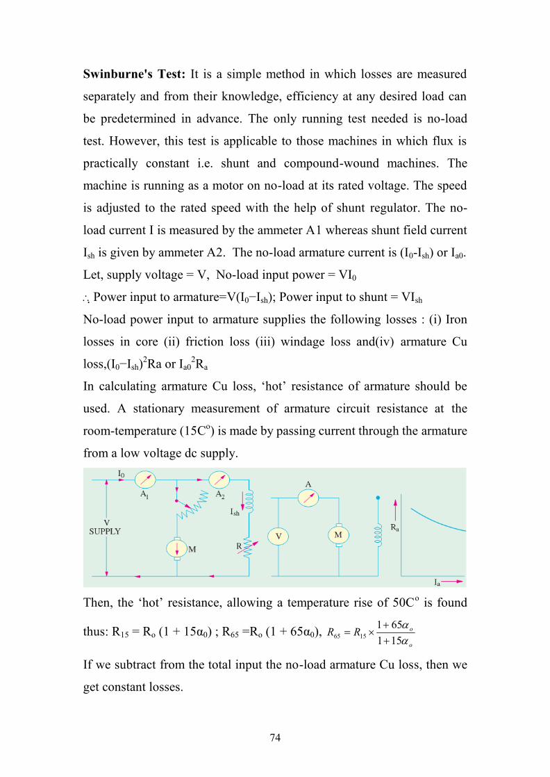
Swinburne's Test: It is a simple method in which losses are measured
separately and from their knowledge, efficiency at any desired load can
be predetermined in advance. The only running test needed is no-load
test. However, this test is applicable to those machines in which flux is
practically constant i.e. shunt and compound-wound machines. The
machine is running as a motor on no-load at its rated voltage. The speed
is adjusted to the rated speed with the help of shunt regulator. The no-
load current I is measured by the ammeter A1 whereas shunt field current
Ish is given by ammeter A2. The no-load armature current is (I0-Ish) or Ia0.
Let, supply voltage = V, No-load input power = VI0
Power input to armature=V(I0−Ish); Power input to shunt = VIsh
No-load power input to armature supplies the following losses : (i) Iron
losses in core (ii) friction loss (iii) windage loss and(iv) armature Cu
loss,(I0−Ish)2Ra or Ia02Ra
In calculating armature Cu loss, ‘hot’ resistance of armature should be
used. A stationary measurement of armature circuit resistance at the
room-temperature (15Co) is made by passing current through the armature
from a low voltage dc supply.
Then, the ‘hot’ resistance, allowing a temperature rise of 50Co is found
thus: R15 = Ro (1 + 15α0) ; R65 =Ro (1 + 65α0),o
oRR
151651
1565
If we subtract from the total input the no-load armature Cu loss, then we
get constant losses.
75
Constant losses Wc= VI0−(I0−Ish)2Ra
Knowing the constant losses of the machine, its efficiency at any other
load can be determined as given below. Let I = load current at which
efficiency is required.
Then, armature current is Ia= I − Ish ...if machine is motoring
= I + Ish ...if machine is generating
Efficiency when running as a motor
Input = VI, Armature Cu loss = Ia2Ra=(I-Ish)2Ra
Constant losses = Wc
Total losses = (I−Ish)2Ra+Wc; VIWRIIVI
inputlossesinput cash
m
2)(
Efficiency when running as a generator
Output = VI ; Armature Cu loss = (I + Ish)2Ra; constant loss=Wc
Total losses = (I+Ish)2R+Wc;cash
g WRIIVIVI
lossesoutputoutput
2)(
Advantages of Swinburne’s Test:
1. It is convenient and economical because power required to test a large
machine is small i.e. only no-load input power.
2. The efficiency can be predetermined at any load because constant-
losses are known.
Main Disadvantages
1. No account is taken of the change in iron losses from no-load to full-
load. At full-load, due to armature reaction, flux is distorted which
increases the iron losses in some cases by as much as 50%.
2. As the test is on no-load, it is impossible to know whether
commutation would be satisfactory at full-load and whether the
temperature rise would be within the specified limits.
76
Regenerative or Hopkinson's Test (Back to Back Test): By this
method, full-load test can be carried out on two shunt machines,
preferably identical ones, without wasting their outputs. The two
machines are mechanically coupled and are so adjusted electrically that
one of them runs as a motor and the other as a generator. The mechanical
output of the motor drives the generator and the electrical output of
generator is used in supplying the greater part of input to the motor. If
there were no losses in the machines, they would have run without any
external power supply. But due to these losses, generator output is not
sufficient to drive the motor and vice-versa. The losses are supplied either
by an extra motor which is belt-connected to the motor-generator set, or
by electrically from the supply mains. The two shunt machines are
connected in parallel. They are, to begin with, started as unloaded motors.
Then, the field of one is weakened and that of the other is strengthened so
that the former runs as a motor and the latter as a generator. The usual
method of procedure is as follows: Machine M is started up from the
supply mains with the help of a starter (not shown) whereas main switch
S of the other machine is kept open. Its speed is adjusted to normal value
by means of its field regulator. Machine M drives machine G as a
generator and its voltage is read on voltmeter V. The voltage of G is
adjusted by its field regulator until voltmeter V1 reads zero, thereby
showing that its voltage is the same, both in polarity and magnitude as
that of the main supply. Thereafter, S is closed to parallel the machines.
By adjusting the respective field regulators, any load can now be thrown
on to the machines. Generator current I1 can be adjusted to any desired
value by increasing the excitation of G or by reducing the excitation of M
and the corresponding values of different ammeters are read. The
electrical output of the generator plus the small power taken from the
77
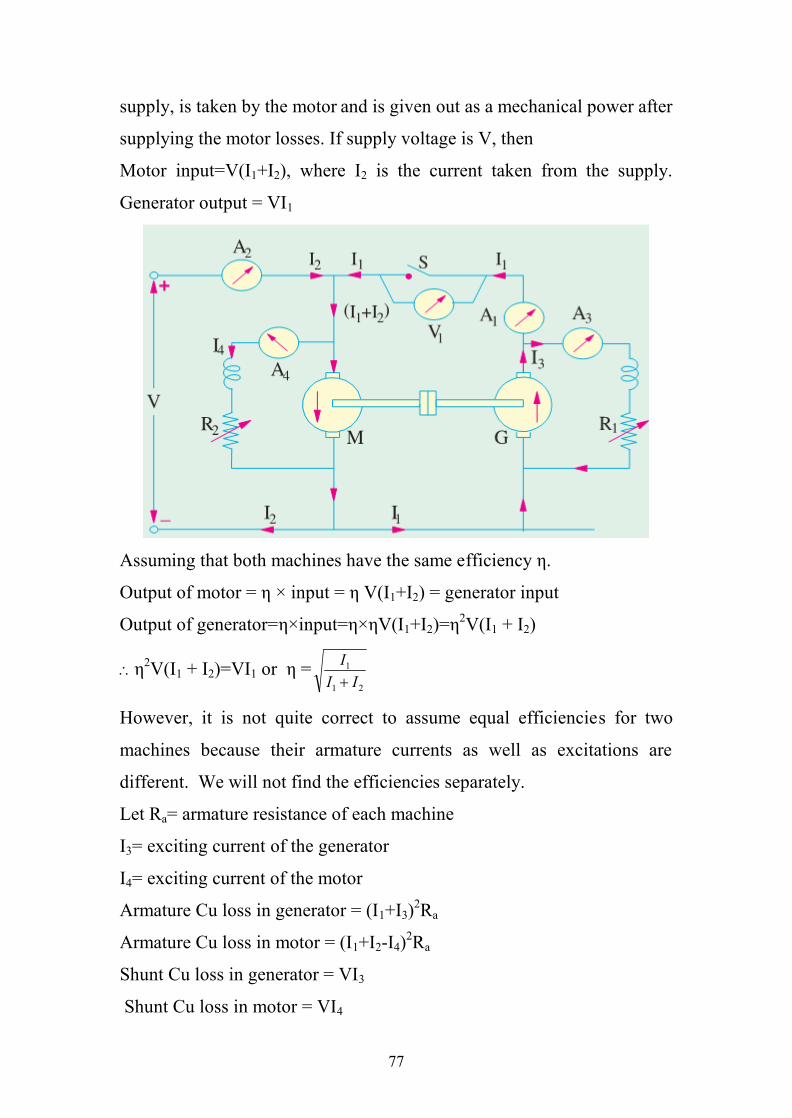
supply, is taken by the motor and is given out as a mechanical power after
supplying the motor losses. If supply voltage is V, then
Motor input=V(I1+I2), where I2 is the current taken from the supply.
Generator output = VI1
Assuming that both machines have the same efficiency η.
Output of motor = η × input = η V(I1+I2) = generator input
Output of generator=η×input=η×ηV(I1+I2)=η2V(I1 + I2)
η2V(I1 + I2)=VI1 or η =21
1
III
However, it is not quite correct to assume equal efficiencies for two
machines because their armature currents as well as excitations are
different. We will not find the efficiencies separately.
Let Ra= armature resistance of each machine
I3= exciting current of the generator
I4= exciting current of the motor
Armature Cu loss in generator = (I1+I3)2Ra
Armature Cu loss in motor = (I1+I2-I4)2Ra
Shunt Cu loss in generator = VI3
Shunt Cu loss in motor = VI4
78
But total motor and generator losses are equal to the power supplied by
the mains. Power drawn from supply = VI2
If we subtract the armature and shunt Cu losses from this, we get the stray
losses of both machines.
Total stray losses for the set= VI2−[(I1+I3)2Ra+(I1+I2−I4)2Ra+VI3+VI4]=W
Making one assumption that stray losses are equally divided between the
two machines, we have Stray loss per machine = W/2
For Generator
Total losses = (I1+I3)2Ra+VI3+W/2=Wg
Output=VI1g
g WVIVI
1
1
For Motor
Total losses = (I1+I2-I4)2Ra+VI4+W/2=Wm
Input = V(I1+I2) )()(
21
21
IIVWIIV m
m
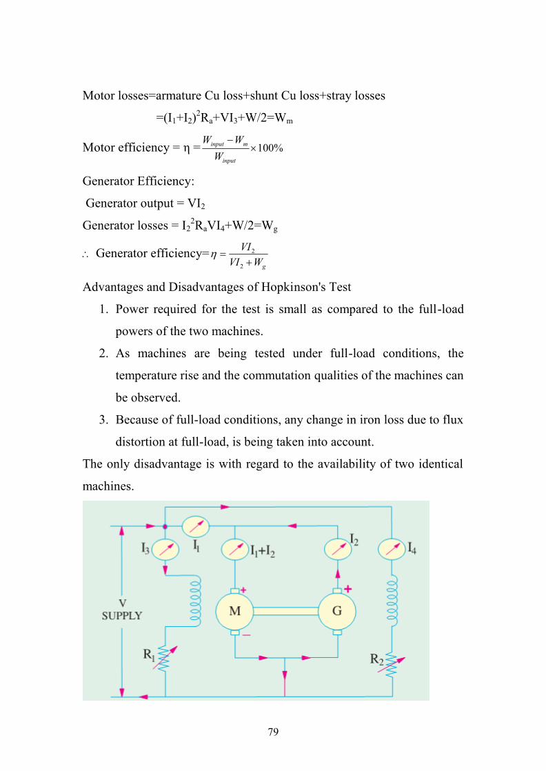
Alternative Connections for Hopkinson’s Test: the following figure
shows in slightly different method of connecting the two machines to the
supply. Here, the main difference is that the shunt windings are directly
connected across the lines. Hence, the line input current is I1 excluding
the field currents. The efficiencies can be calculated as detailed below:
Motor armature Cu loss = (I1+I2)2Ra
Generator armature Cu loss = I22Ra
Power drawn from the supply =Winput =VI1
Total stray losses i.e. iron, friction and windage losses for the two
machines are = VI1−[(I1+I2)2Ra− I22 Ra] = W
Stray loss for each machine = W/2
Motor Efficiency
Motor input = armature input + shunt field input = V ( I1+I2)+VI3+Winput
79
Motor losses=armature Cu loss+shunt Cu loss+stray losses
=(I1+I2)2Ra+VI3+W/2=Wm
Motor efficiency = η = %100
input
minput
WWW
Generator Efficiency:
Generator output = VI2
Generator losses = I22RaVI4+W/2=Wg
Generator efficiency=gWVI
VI
2
2
Advantages and Disadvantages of Hopkinson's Test
1. Power required for the test is small as compared to the full-load
powers of the two machines.
2. As machines are being tested under full-load conditions, the
temperature rise and the commutation qualities of the machines can
be observed.
3. Because of full-load conditions, any change in iron loss due to flux
distortion at full-load, is being taken into account.
The only disadvantage is with regard to the availability of two identical
machines.
80
13- The no-load test of a 44.76 kW, 220 V dc shunt motor gave thefollowing figures: Input current=13.25 A; field current=2.55 A;resistance of armature at 75Co = 0.032Ω and brush drop =2 V.Estimate the full-load current and efficiency.[90%]
14- A 250V, 14.92 kW shunt motor has a maximum efficiency of 88% anda speed of 700 rpm when delivering 80% of its rated output. Theresistance of its shunt field is 100Ω. Determine the efficiency andspeed when the motor draws a current of 78 A from the mains.[ 86.9%,680 rpm]
15- The Hopkinson’s test on two similar shunt machines gave thefollowing full-load data: Line voltage=110V Field currents are 3A and3.5A Line current = 48A Armature resistance of each is 0.035Ω Motorarmature current=230A Calculate the efficiency of each machineassuming a brush contact drop of 1 volt per brush.[ 88.8%, 89.4%]
16- The Hopkinson’s test on two shunt machines gave the following resultsfor full-load: Line voltage=250V; current taken from supply systemexcluding field currents =50A; motor armature current = 380 A; fieldcurrents 5A and 4.2A. Calculate the efficiency of the machine workingas a generator. Armature resistance of each machine is 0.2 Ω.[92.02%]