Sony Xm 552zr
20
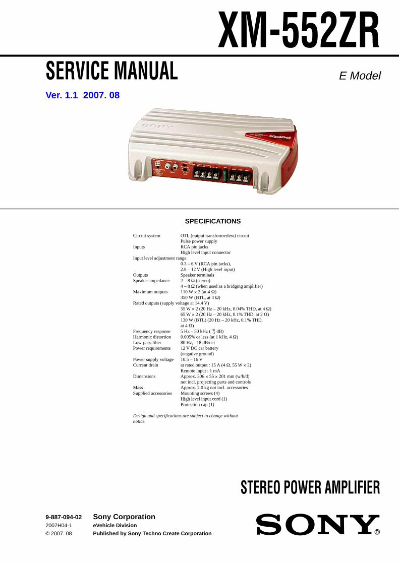
1 SERVICE MANUAL E Model XM-552ZR STEREO POWER AMPLIFIER Circuit system OTL (output transformerless) circuit Pulse power supply Inputs RCA pin jacks High level input connector Input level adjustment range 0.3 – 6 V (RCA pin jacks), 2.8 – 12 V (High level input) Outputs Speaker terminals Speaker impedance 2 – 8 Ω (stereo) 4 – 8 Ω (when used as a bridging amplifier) Maximum outputs 110 W × 2 (at 4 Ω) 350 W (BTL, at 4 Ω) Rated outputs (supply voltage at 14.4 V) 55 W × 2 (20 Hz – 20 kHz, 0.04% THD, at 4 Ω) 65 W × 2 (20 Hz – 20 kHz, 0.1% THD, at 2 Ω) 130 W (BTL) (20 Hz – 20 kHz, 0.1% THD, at 4 Ω) Frequency response 5 Hz – 50 kHz ( dB) Harmonic distortion 0.005% or less (at 1 kHz, 4 Ω) Low-pass filter 80 Hz, –18 dB/oct Power requirements 12 V DC car battery (negative ground) Power supply voltage 10.5 – 16 V Current drain at rated output : 15 A (4 Ω, 55 W × 2) Remote input : 1 mA Dimensions Approx. 306 × 55 × 201 mm (w/h/d) not incl. projecting parts and controls Mass Approx. 2.0 kg not incl. accessories Supplied accessories Mounting screws (4) High level input cord (1) Protection cap (1) Design and specifications are subject to change without notice. SPECIFICATIONS +0 –3 Ver. 1.1 2007. 08 9-887-094-02 2007H04-1 © 2007. 08 Sony Corporation eVehicle Division Published by Sony Techno Create Corporation
-
Upload
andres-eduardo-raymond-claros -
Category
Documents
-
view
815 -
download
52
Transcript of Sony Xm 552zr
1
SERVICE MANUAL E Model
XM-552ZR
STEREO POWER AMPLIFIER
Circuit system OTL (output transformerless) circuitPulse power supply
Inputs RCA pin jacksHigh level input connector
Input level adjustment range0.3 – 6 V (RCA pin jacks),2.8 – 12 V (High level input)
Outputs Speaker terminalsSpeaker impedance 2 – 8 Ω (stereo)
4 – 8 Ω (when used as a bridging amplifier)Maximum outputs 110 W × 2 (at 4 Ω)
350 W (BTL, at 4 Ω)Rated outputs (supply voltage at 14.4 V)
55 W × 2 (20 Hz – 20 kHz, 0.04% THD, at 4 Ω)65 W × 2 (20 Hz – 20 kHz, 0.1% THD, at 2 Ω)130 W (BTL) (20 Hz – 20 kHz, 0.1% THD,at 4 Ω)
Frequency response 5 Hz – 50 kHz ( dB)Harmonic distortion 0.005% or less (at 1 kHz, 4 Ω)Low-pass filter 80 Hz, –18 dB/octPower requirements 12 V DC car battery
(negative ground)Power supply voltage 10.5 – 16 VCurrent drain at rated output : 15 A (4 Ω, 55 W × 2)
Remote input : 1 mADimensions Approx. 306 × 55 × 201 mm (w/h/d)
not incl. projecting parts and controlsMass Approx. 2.0 kg not incl. accessoriesSupplied accessories Mounting screws (4)
High level input cord (1)Protection cap (1)
Design and specifications are subject to change withoutnotice.
SPECIFICATIONS
+0–3
Ver. 1.1 2007. 08
9-887-094-022007H04-1
© 2007. 08
Sony CorporationeVehicle Division
Published by Sony Techno Create Corporation
2
TABLE OF CONTENTS
1. GENERALLocation and Function of Controls .......................................... 3Connections ............................................................................. 4
2. DISASSEMBLY2-1. Bottom Plate ........................................................................ 72-2. AMP Board Section ............................................................ 82-3. Panel (Front) ........................................................................ 8
3. DIAGRAMS3-1. Block Diagram .................................................................... 93-2. Printed Wiring Board ........................................................ 113-3. Schematic Diagram ........................................................... 12
4. EXPLODED VIEWS4-1. Heat Sink (Main) Section .................................................. 144-2. AMP Board Section .......................................................... 15
5. ELECTRICAL PARTS LIST ........................................ 16
XM-552ZR
PROTECTOR OPERATION CHECK
Thermal Protect1. Short across TH901 with the power on.2. Verify that the protector is operated and LED901 illuminates
green. When input the signal and verify that there is no outputon the SP-OUT even when the volume is increased.
3. Verify that the protector is released and there is an output on theSP-OUT when the short is removed.
4. Likewise, perform items 1 to 3 for TH902 and TH903.
Over Current Protect1. Short between the positive and negative sides of the speaker
output terminal CN904 with the power on.(Perform this shorting for each channel on L and R.)
2. Verify that the protector is operated and LED901 illuminatesred.
3. Verify that the protector is not released and LED901 remainsred even when the short is removed.
4. Verify that the protector is released and LED901 illuminates greenwhen the power is turned off and then on again.
Offset Protect1. Short between the +12V terminal of CN903 and the BTL+ or
BTL– of the speaker output terminal CN904.(Short between +12V terminal and BTL+ and between +12Vterminal and BTL–.)
2. Verify that the protector is operated and LED901 illuminatesred.
3. Verify that the protector is not released and LED901 remainsred even when the short is removed.
4. Verify that the protector is released and LED901 illuminates greenwhen the power is turned off and then on again.
SAFETY-RELATED COMPONENT WARNING!!
COMPONENTS IDENTIFIED BY MARK 0 OR DOTTED LINEWITH MARK 0 ON THE SCHEMATIC DIAGRAMS AND INTHE PARTS LIST ARE CRITICAL TO SAFE OPERATION.REPLACE THESE COMPONENTS WITH SONY PARTS WHOSEPART NUMBERS APPEAR AS SHOWN IN THIS MANUAL ORIN SUPPLEMENTS PUBLISHED BY SONY.
UNLEADED SOLDERBoards requiring use of unleaded solder are printed with the leadfree mark (LF) indicating the solder contains no lead.(Caution: Some printed circuit boards may not come printed withthe lead free mark due to their particular size.)
: LEAD FREE MARKUnleaded solder has the following characteristics.• Unleaded solder melts at a temperature about 40°C higher than
ordinary solder.Ordinary soldering irons can be used but the iron tip has to beapplied to the solder joint for a slightly longer time.Soldering irons using a temperature regulator should be set toabout 350°C.Caution: The printed pattern (copper foil) may peel away if theheated tip is applied for too long, so be careful!
• Strong viscosityUnleaded solder is more viscous (sticky, less prone to flow)than ordinary solder so use caution not to let solder bridgesoccur such as on IC pins, etc.
• Usable with ordinary solderIt is best to use only unleaded solder but unleaded solder mayalso be added to ordinary solder.
Notes on Chip Component Replacement• Never reuse a disconnected chip component.• Notice that the minus side of a tantalum capacitor may be
damaged by heat.
Ver. 1.1
3
XM-552ZRSECTION 1GENERAL This section is extracted
from instruction manual.
Location and Function of Controls
Emplacement et fonction des commandes
Ubicación y función de los controles
POWER/PROTECTOR
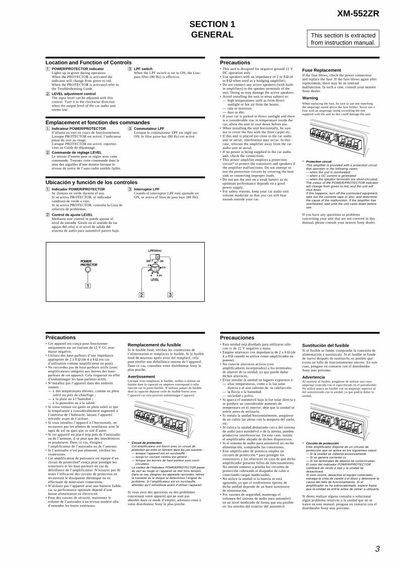
1 POWER/PROTECTOR indicatorLights up in green during operation.When the PROTECTOR is activated theindicator will change from green to red.When the PROTECTOR is activated refer tothe Troubleshooting Guide.
2 LEVEL adjustment controlThe input level can be adjusted with thiscontrol. Turn it in the clockwise directionwhen the output level of the car audio unitseems low.
3 LPF switchWhen the LPF switch is set to ON, the Low-pass filter (80 Hz) is effective.
1 Indicateur POWER/PROTECTORS’allume en vert en cours de fonctionnement.Lorsque PROTECTOR est activé, l’indicateurpasse du vert au rouge.Lorsque PROTECTOR est activé, reportez-vous au Guide de dépannage.
2 Commande de réglage LEVELLe niveau d’entrée peut se régler avec cettecommande. Tournez cette commande dans lesens des aiguilles d’une montre lorsque leniveau de sortie de l’auto-radio semble faible.
3 Commutateur LPFLorsque le commutateur LPF est réglé surON, le filtre passe-bas (80 Hz) est activé.
1 Indicador POWER/PROTECTORSe ilumina en verde durante el uso.Si se activa PROTECTOR, el indicadorcambiará de verde a rojo.Si se activa PROTECTOR, consulte la Guía desolución de problemas.
2 Control de ajuste LEVELMediante este control se puede ajustar elnivel de entrada. Gírelo en el sentido de lasagujas del reloj si el nivel de salida delsistema de audio para automóvil parece bajo.
3 Interruptor LPFCuando el interruptor LPF está ajustado enON, se activa el filtro de paso bajo (80 Hz).
(80Hz)LPF
LEVEL
OFF ON12
4
6 0.3V
0.5
Precautions• This unit is designed for negative ground 12 V
DC operation only.• Use speakers with an impedance of 2 to 8 Ω (4
to 8 Ω when used as a bridging amplifier).• Do not connect any active speakers (with built-
in amplifiers) to the speaker terminals of theunit. Doing so may damage the active speakers.
• Avoid installing the unit in areas subject to:— high temperatures such as from direct
sunlight or hot air from the heater.— rain or moisture.— dust or dirt.
• If your car is parked in direct sunlight and thereis a considerable rise in temperature inside thecar, allow the unit to cool down before use.
• When installing the unit horizontally, be surenot to cover the fins with the floor carpet etc.
• If this unit is placed too close to the car audiounit or aerial, interference may occur. In thiscase, relocate the amplifier away from the caraudio unit or aerial.
• If no power is being supplied to the car audiounit, check the connections.
• This power amplifier employs a protectioncircuit* to protect the transistors and speakers ifthe amplifier malfunctions. Do not attempt totest the protection circuits by covering the heatsink or connecting improper loads.
• Do not use the unit on a weak battery as itsoptimum performance depends on a goodpower supply.
• For safety reasons, keep your car audio unitvolume moderate so that you can still hearsounds outside your car.
Fuse ReplacementIf the fuse blows, check the power connectionand replace the fuse. If the fuse blows again afterreplacement, there may be an internalmalfunction. In such a case, consult your nearestSony dealer.
WarningWhen replacing the fuse, be sure to use one matchingthe amperage stated above the fuse holder. Never use afuse with an amperage rating exceeding the onesupplied with the unit as this could damage the unit.
* Protection circuitThis amplifier is provided with a protection circuitthat operates in the following cases:— when the unit is overheated— when a DC current is generated— when the speaker terminals are short-circuited.The colour of the POWER/PROTECTOR indicatorwill change from green to red, and the unit willshut down.If this happens, turn off the connected equipment,take out the cassette tape or disc, and determinethe cause of the malfunction. If the amplifier hasoverheated, wait until the unit cools down beforeuse.
If you have any questions or problemsconcerning your unit that are not covered in thismanual, please consult your nearest Sony dealer.
Précautions• Cet appareil est conçu pour fonctionner
uniquement sur un courant de 12 V CC avecmasse négative.
• Utilisez des haut-parleurs d’une impédanceappropriée de 2 à 8 Ω (de 4 à 8 Ω (en casd’utilisation comme amplificateur en pont).
• Ne raccordez pas de haut-parleurs actifs (avecamplificateurs intégrés) aux bornes des haut-parleurs de cet appareil. Cela risquerait en effetd’endommager les haut-parleurs actifs.
• N’installez pas l’appareil dans des endroitssoumis :— à des températures élevées, comme en plein
soleil ou près du chauffage ;— à la pluie ou à l’humidité ;— à la poussière ou à la saleté.
• Si votre voiture est garée en plein soleil et quela température a considérablement augmenté àl’intérieur de l’habitacle, laissez l’appareilrefroidir avant de l’utiliser.
• Si vous installez l’appareil à l’horizontale, nerecouvrez pas les ailettes de ventilation avec letapis de sol ou quoi que ce soit d’autre.
• Si cet appareil est placé trop près de l’autoradioou de l’antenne, il se peut que des interférencesse produisent. Dans ce cas, éloignezl’amplificateur de l’autoradio ou de l’antenne.
• Si l’autoradio n’est pas alimenté, vérifiez lesconnexions.
• Cet amplificateur de puissance est équipé d’uncircuit de protection* conçu pour protéger lestransistors et les haut-parleurs en cas dedéfaillance de l’amplificateur. N’essayez pas detester l’efficacité des circuits de protection enrecouvrant le dissipateur thermique ou eneffectuant de mauvaises connexions.
• N’utilisez pas l’appareil avec une batterie faible,car sa performance optimale dépend d’unebonne alimentation en électricité.
• Pour des raisons de sécurité, maintenez levolume de l’autoradio à un niveau modéré afind’entendre les bruits extérieurs.
Remplacement du fusibleSi le fusible fond, vérifiez les connexions del’alimentation et remplacez le fusible. Si le fusiblefond de nouveau après avoir été remplacé, celapeut révéler une défaillance interne de l’appareil.Dans ce cas, consultez votre distributeur Sony leplus proche.
AvertissementLorsque vous remplacez le fusible, veillez à utiliser unfusible dont la capacité en ampères correspond à celleinscrite sur le porte-fusible. N’utilisez jamais de fusibledont la capacité dépasse celle du fusible fourni avecl’appareil car cela pourrait endommager l’appareil.
* Circuit de protectionCet amplificateur est fourni avec un circuit deprotection qui entre en fonction dans les cas suivants :— lorsque l’appareil est en surchauffe ;— lorsqu’un courant continu est généré ;— lorsque les bornes de haut-parleur sont court-
circuitées.La couleur de l’indicateur POWER/PROTECTOR passedu vert au rouge et l’appareil se met hors tension.Dans ce cas, éteignez les appareils raccordés, retirezla cassette ou le disque et déterminez l’origine duproblème. Si l’amplificateur est en surchauffe,attendez qu’il refroidisse avant d’utiliser l’appareil.
Si vous avez des questions ou des problèmesconcernant votre appareil qui ne sont pasabordés dans ce mode d’emploi, adressez-vous àvotre distributeur Sony le plus proche.
Sustitución del fusibleSi el fusible se funde, compruebe la conexión dealimentación y sustitúyalo. Si el fusible se fundede nuevo después de sustituirlo, es posible queexista un fallo de funcionamiento interno. En estecaso, póngase en contacto con el distribuidorSony más próximo.
AdvertenciaAl sustituir el fusible, asegúrese de utilizar uno cuyoamperaje coincida con el especificado en el portafusible.No utilice nunca un fusible con un amperaje superior aldel suministrado con la unidad, ya que podría dañar launidad.
* Circuito de protecciónEste amplificador dispone de un circuito deprotección que se activa en los siguientes casos:— Si la unidad se calienta excesivamente— Si se genera corriente cc— Si los terminales de altavoz se cortocircuitan.El color del indicador POWER/PROTECTORcambiará de verde a rojo y la unidad sedesactivará.Si esto ocurre, desactive el equipo conectado,extraiga la cinta de casete o el disco y determine lacausa del fallo de funcionamiento. Si elamplificador se ha sobrecalentado, espere hastaque la unidad se enfríe antes de volver a utilizarla.
Si desea realizar alguna consulta o solucionaralgún problema relativos a la unidad que no setraten en este manual, póngase en contacto con eldistribuidor Sony más próximo.
Precauciones• Esta unidad está diseñada para utilizarse sólo
con cc de 12 V negativo a masa.• Emplee altavoces con impedancia de 2 a 8 Ω (de
4 a 8 Ω cuando se utilice como amplificador enpuente).
• No conecte altavoces activos (conamplificadores incorporados) a los terminalesde altavoz de la unidad, ya que puede dañardichos altavoces.
• Evite instalar la unidad en lugares expuestos a:— altas temperaturas, como a la luz solar
directa o al aire caliente de la calefacción.— la lluvia o la humedad.— suciedad o polvo.
• Si aparca el automóvil bajo la luz solar directa yse produce un considerable aumento detemperatura en el interior, deje que la unidad seenfríe antes de utilizarla.
• Si instala la unidad horizontalmente, asegúresede no cubrir las aletas con la moqueta del suelo,etc.
• Si coloca la unidad demasiado cerca del sistemade audio para automóvil o de la antena, puedenproducirse interferencias. En este caso, instaleel amplificador alejado de dichos dispositivos.
• Si el sistema de audio para automóvil no recibealimentación, compruebe las conexiones.
• Este amplificador de potencia emplea uncircuito de protección * para proteger lostransistores y los altavoces en caso de que dichoamplificador presente fallos de funcionamiento.No intente someter a prueba los circuitos deprotección cubriendo el disipador de calor oconectando cargas inadecuadas.
• No utilice la unidad si la batería se estáagotando, ya que el rendimiento óptimo dedicha unidad depende de un buen suministrode alimentación.
• Por razones de seguridad, mantenga elvolumen del sistema de audio para automóvilen un nivel moderado de forma que sea posibleoír los sonidos del exterior del automóvil.
4
XM-552ZR
Connections
Installation
Instalación
1
Installation
Mount the unit as illustrated.Montez l’appareil comme illustré.Monte la unidad tal como se muestraen la ilustración.
Before Installation• Mount the unit either inside the trunk or under
a seat.• Choose the mounting location carefully so the
unit will not interfere with the normalmovements of the driver and it will not beexposed to direct sunlight or hot air from theheater.
• Do not install the unit under the floor carpet,where the heat dissipation from the unit will beconsiderably impaired.
First, place the unit where you plan to install it,and mark the positions of the 4 screw holes onthe mounting board (not supplied). Then drill a 3mm ( 1/ 8 in) pilot hole at each mark and mountthe unit onto the board with the suppliedmounting screws. The mounting screws are all15 mm (19/ 32 in) long, so make sure that themounting board is thicker than 15 mm ( 19/ 32 in).
Avant l’installation• Installez l’appareil dans le coffre ou sous un
siège.• Choisissez soigneusement l’emplacement de
montage afin d’éviter que l’appareil ne gêne leconducteur dans ses mouvements et qu’il nesoit pas exposé au rayonnement direct du soleilou à l’air chaud du radiateur.
• N’installez pas l’appareil sous le tapis de sol carla dissipation thermique ne pourrait pas se fairecorrectement.
Posez d’abord l’appareil à l’endroit où voussouhaitez l’installer et tracez un repère depositionnement pour les 4 orifices de vis sur laplaque de montage (non fournie). Percez desorifices de 3 mm (1/ 8 po) au niveau de chaquerepère et fixez l’appareil sur la plaque avec les visde montage fournies. La longueur des vis demontage est de 15 mm ( 19/ 32 po). Assurez-vousdonc que l’épaisseur de la plaque de montage estsupérieure à 15 mm ( 19/ 32 po).
Antes de realizar la instalación• Monte la unidad en el interior del maletero o
debajo de un asiento.• Elija cuidadosamente el lugar de instalación de
forma que la unidad no dificulte las maniobrasnormales del conductor y no quede expuesta ala luz solar directa ni al aire caliente de lacalefacción.
• No instale la unidad debajo de la moqueta delsuelo, en cuyo caso la disipación de calor de lamisma disminuirá considerablemente.
En primer lugar, coloque la unidad donde tengaprevisto instalarla y marque sobre la superficiedel tablero de montaje (no suministrado) lasposiciones de los 4 orificios para los tornillos. Acontinuación, perfore los orificios con undiámetro de aproximadamente 3 mm y monte launidad sobre el tablero con los tornillos demontaje suministrados. Ya que la longitud deestos tornillos es de 15 mm, compruebe que elgrosor del tablero de montaje sea superior a 15mm.
Avertissements
Cautions
Precauciones
• Before making any connections, disconnect theground terminal of the car battery to avoidshort circuits.
• Be sure to use speakers with an adequate powerrating. If you use small capacity speakers, theymay be damaged.
• This is a Phase-Inverted Amplifier.• Do not connect the # terminal of the speaker
system to the car chassis, and do not connectthe # terminal of the right speaker with that ofthe left speaker.
• Install the input and output cords away fromthe power supply wire as running them close
together can generate some interference noise.• This unit is a high powered amplifier.
Therefore, it may not perform to its fullpotential if used with the speaker cordssupplied with the car.
• If your car is equipped with a computer systemfor navigation or some other purpose, do notremove the ground wire from the car battery. Ifyou disconnect the wire, the computer memorymay be erased. To avoid short circuits whenmaking connections, disconnect the +12 Vpower supply wire until all the other wireshave been connected.
• Avant d’effectuer les raccordements,débranchez la borne de masse de la batterie devoiture pour éviter de provoquer un court-circuit.
• Utilisez des haut-parleurs d’une capacitéadéquate. Si vous utilisez des haut-parleurs defaible capacité, ils risquent d’être endommagés.
• Les phases de cet amplificateur sont inversées.• Ne raccordez pas la borne # du système de
haut-parleurs à la carrosserie de la voiture, oula borne # du haut-parleur droit à celle duhaut-parleur gauche.
• Eloignez les cordons d’entrée et de sortie du fild’alimentation électrique afin d’éviter que des
interférences ne se produisent.• Cet appareil est un amplificateur de haute
puissance. Il se peut donc qu’il n’atteigne pas sapuissance maximale s’il est utilisé avec lescordons de haut-parleurs de la voiture.
• Si votre voiture est équipée d’un ordinateur debord pour la navigation ou autre, ne débranchezpas le fil de masse de la batterie de la voiture. Sivous débranchez ce fil, toute la mémoire del’ordinateur risque d’être effacée. Pour évitertout risque de court-circuit lorsque vouseffectuez les raccordements, branchez le fild’alimentation de +12 V uniquement aprèsavoir branché tous les autres fils.
• Antes de realizar las conexiones, desconecte elterminal de toma a tierra de la batería delautomóvil para evitar cortocircuitos.
• Asegúrese de utilizar altavoces con unapotencia nominal adecuada. Si empleaaltavoces de capacidad reducida, puedendañarse.
• Este amplificador es de fase invertida.• No conecte el terminal # del sistema de
altavoces al chasis del automóvil, ni el terminal# del altavoz derecho al del altavoz izquierdo.
• Instale los cables de entrada y salida alejadosdel cable de la fuente de alimentación, ya queen caso contrario puede generarse ruido por
interferencias.• Esta unidad es un amplificador de alta
potencia. Por tanto, puede no funcionar a plenorendimiento si se utiliza con los cables dealtavoz suministrados con el automóvil.
• Si el automóvil está equipado con un sistema deordenador para la navegación o para otrafinalidad, no desconecte el conductor de toma atierra de la batería del automóvil. Si lodesconecta, la memoria del ordenador puedeborrarse. Para evitar cortocircuitos al realizarlas conexiones, desconecte el cable de la fuentede alimentación de +12 V hasta conectar todoslos cables.
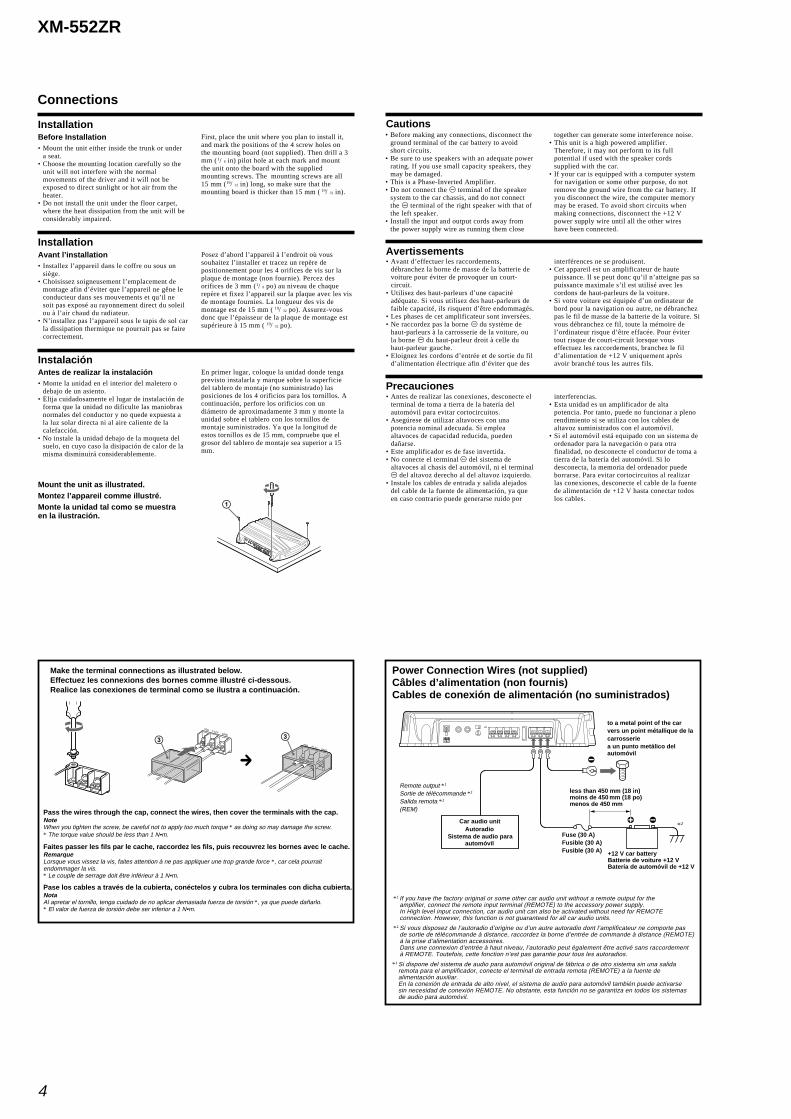
Make the terminal connections as illustrated below.Effectuez les connexions des bornes comme illustré ci-dessous.Realice las conexiones de terminal como se ilustra a continuación.
Pass the wires through the cap, connect the wires, then cover the terminals with the cap.NoteWhen you tighten the screw, be careful not to apply too much torque * as doing so may damage the screw.* The torque value should be less than 1 N•m.
Faites passer les fils par le cache, raccordez les fils, puis recouvrez les bornes avec le cache.RemarqueLorsque vous vissez la vis, faites attention à ne pas appliquer une trop grande force *, car cela pourraitendommager la vis.* Le couple de serrage doit être inférieur à 1 N•m.
Pase los cables a través de la cubierta, conéctelos y cubra los terminales con dicha cubierta.NotaAl apretar el tornillo, tenga cuidado de no aplicar demasiada fuerza de torsión *, ya que puede dañarlo.* El valor de fuerza de torsión debe ser inferior a 1 N•m.
REM +12V GND
REM +12V GND
3 3
c
Power Connection Wires (not supplied)Câbles d’alimentation (non fournis)Cables de conexión de alimentación (no suministrados)
to a metal point of the carvers un point métallique de lacarrosseriea un punto metálico delautomóvil
Fuse (30 A)Fusible (30 A)Fusible (30 A) +12 V car battery
Batterie de voiture +12 VBatería de automóvil de +12 V
Car audio unitAutoradio
Sistema de audio paraautomóvil
Remote output *1
Sortie de télécommande *1
Salida remota *1
(REM)
less than 450 mm (18 in)moins de 450 mm (18 po)menos de 450 mm
*1 If you have the factory original or some other car audio unit without a remote output for theamplifier, connect the remote input terminal (REMOTE) to the accessory power supply.In High level input connection, car audio unit can also be activated without need for REMOTEconnection. However, this function is not guaranteed for all car audio units.
*1 Si vous disposez de l’autoradio d’origine ou d’un autre autoradio dont l’amplificateur ne comporte pasde sortie de télécommande à distance, raccordez la borne d’entrée de commande à distance (REMOTE)à la prise d’alimentation accessoires.Dans une connexion d’entrée à haut niveau, l’autoradio peut également être activé sans raccordementà REMOTE. Toutefois, cette fonction n’est pas garantie pour tous les autoradios.
*1 Si dispone del sistema de audio para automóvil original de fábrica o de otro sistema sin una salidaremota para el amplificador, conecte el terminal de entrada remota (REMOTE) a la fuente dealimentación auxiliar.En la conexión de entrada de alto nivel, el sistema de audio para automóvil también puede activarsesin necesidad de conexión REMOTE. No obstante, esta función no se garantiza en todos los sistemasde audio para automóvil.
*2
5
XM-552ZR
Remarques sur l’alimentation électrique• Raccordez le câble d’alimentation +12 V
uniquement après avoir réalisé toutes les autresconnexions.
• Raccordez solidement le fil de masse de l’appareil àun point métallique de la carrosserie. Uneconnexion lâche risque de provoquer un problèmede fonctionnement de l’amplificateur.
• Veillez à raccorder le fil de commande à distance del’autoradio à la borne de commande à distance.
• Si vous utilisez un autoradio dont l’amplificateur necomporte pas de sortie de commande à distance,raccordez la borne d’entrée de commande àdistance (REMOTE) à la prise d’alimentationaccessoires.
• Utilisez un câble d’alimentation doté d’un fusible(30 A).
Notes on the power supply• Connect the +12 V power supply wire only after all
the other wires have been connected.• Be sure to connect the ground wire of the unit
securely to a metal point of the car. A looseconnection may cause a malfunction of theamplifier.
• Be sure to connect the remote control wire of thecar audio unit to the remote terminal.
• When using a car audio unit without a remoteoutput on the amplifier, connect the remote inputterminal (REMOTE) to the accessory power supply.
• Use a power supply wire with a fuse attached (30A).
Notas sobre la fuente de alimentación• Conecte el cable de la fuente de alimentación de
+12 V sólo después de haber conectado los otroscables.
• Asegúrese de conectar firmemente el cable detoma a tierra de la unidad a un punto metálico delautomóvil. Una conexión floja puede causar fallosde funcionamiento del amplificador.
• Compruebe que conecta el cable de control remotodel sistema de audio para automóvil al terminalremoto.
• Si utiliza un sistema de audio para automóvil sinsalida remota en el amplificador, conecte elterminal de entrada remota (REMOTE) a la fuentede alimentación auxiliar.
• Emplee el cable de la fuente de alimentación conun fusible fijado (30 A).
• All power wires connected to the positive batterypost should be fused within 450 mm (18 in) of thebattery post, and before they pass through anymetal.
• Make sure that the vehicle’s battery wiresconnected to the vehicle (ground to chassis) *2 areof a wire gauge at least equal to that of the mainpower wire connected from the battery to theamplifier.
• During full-power operation, a current of morethan 30 A will run through the system. Therefore,make sure that the wires to be connected to the+12 V and GND terminals of this unit are at least14-Gauge (AWG-14) or have a sectional area ofmore than 2 mm2.
• Todos los cables de alimentación conectados al polopositivo de la batería deben conectarse a un fusiblesituado a menos de 450 mm del polo de la batería,y antes de pasar por ninguna pieza metálica.
• Asegúrese de que los cables de la batería delvehículo conectados al mismo (a la masa delchasis) *2 tienen una anchura igual o superior a ladel cable de alimentación principal que conecta labatería con el amplificador.
• Durante el funcionamiento a pleno rendimiento,fluye por el sistema una corriente superior a 30 A.Por tanto, compruebe que los cables que se van aconectar a los terminales +12 V y GND de estaunidad son del calibre 14 (AWG 14) como mínimo opresentan un área de sección superior a 2 mm 2.
• Tous les fils électriques raccordés à la borne positivede la batterie doivent être protégés par un fusible àune distance maximum de 450 mm (18 po) à laborne de la batterie et avant de passer dans unepartie métallique quelconque.
• Assurez-vous que les fils de la batterie du véhiculeraccordés à ce dernier (sol au châssis) *2 sont d’uncalibre au moins égal à celui du fil électriqueprincipal reliant la batterie et l’amplificateur.
• Pendant une utilisation à pleine puissance, uncourant d’une intensité supérieure à 30 A circuledans le système. Assurez-vous que les câbles àraccorder aux bornes +12 V et GND de cet appareilsont de calibre supérieur à 14 (AWG-14) ou d’unesection supérieure à 2 mm 2.
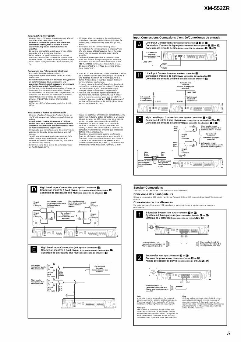
High Level Input Connection (with Speaker Connection 1 or 4)Connexion d’entrée à haut niveau (avec connexion de haut-parleur 1 ou 4)Conexión de entrada de alto nivel (con conexión de altavoces 1 ó 4)
Line Input Connection (with Speaker Connection 3)Connexion d’entrée de ligne (avec connexion de haut-parleur 3)Conexión de entrada de línea (con conexión de altavoces 3)
Line Input Connection (with Speaker Connection 1, 2 or 4)Connexion d’entrée de ligne (avec connexion de haut-parleur 1, 2 ou 4)Conexión de entrada de línea (con conexión de altavoces 1, 2 ó 4)
CCCCC
AAAAA
BBBBB
Left speaker outputSortie de haut-parleur gaucheSalida del altavoz izquierdo
Right speaker outputSortie de haut-parleur droitSalida del altavoz derecho
StripedRayéCon rayas
StripedRayéCon rayas
Car audio unitAutoradio
Sistema de audio paraautomóvil
WhiteBlancBlanco
GreyGrisGris
WhiteBlancBlanco
GreyGrisGris 2RL
LINE OUT
Right channelCanal droitCanal derecho
Left channelCanal gaucheCanal izquierdo
LINE OUT
L (BTL) L (BTL)
Input Connections/Connexions d’entrée/Conexiones de entrada
Car audio unitAutoradio
Sistema de audio paraautomóvil
Car audio unitAutoradio
Sistema de audio paraautomóvil
White/Black stripedRayé blanc/noirCon rayas blancas ynegras
Grey/Black stripedRayé gris/noirCon rayas grises ynegras
High Level Input Connection (with Speaker Connection 2)Connexion d’entrée à haut niveau (avec connexion de haut-parleur 2)Conexión de entrada de alto nivel (con conexión de altavoces 2)
High Level Input Connection (with Speaker Connection 3)Connexion d’entrée à haut niveau (avec connexion de haut-parleur 3)Conexión de entrada de alto nivel (con conexión de altavoces 3)
DDDDD
EEEEE
Right speakerHaut-parleur droitAltavoz derecho
Left speakerHaut-parleur gaucheAltavoz izquierdo
WhiteBlancBlanco
GreyGrisGris
2
StripedRayéCon rayas
StripedRayéCon rayas
Left speaker outputSortie de haut-parleur gaucheSalida del altavozizquierdo
Right speaker outputSortie de haut-parleur droitSalida del altavozderecho
StripedRayéCon rayas
StripedRayéCon rayas
2 2
StripedRayéCon rayas
StripedRayéCon rayas
Car audio unitAutoradio
Sistema de audio paraautomóvil
Car audio unitAutoradio
Sistema de audio paraautomóvil
Conexións des haut-parleursRéglez le commutateur LPF situé à l’arrière de l’appareil à On ou Off, comme indiqué dans l’illustration ci-dessous.
2-Speaker System (with Input Connection A or C)Système à 2 haut-parleurs (avec connexion d’entrée A ou C)Sistema de 2 altavoces (con conexión de entrada A o C)
11111
Subwoofer (with Input Connection A or E)Caisson de graves (avec connexion d’entrée A ou E)Altavoz potenciador de graves (con conexión de entrada A o E)
22222
NotaSi desea utilizar el altavoz potenciador de gravescomo altavoz monoaural, conecte el altavoz talcomo se muestra en la ilustración anterior. Lasseñales de salida enviadas al altavoz potenciador degraves serán una combinación de las señales desalida derecha e izquierda.
(80Hz)
OFF ON
LPF
Left speaker (min. 2 Ω)Haut-parleur gauche (min. 2 Ω)Altavoz izquierdo (mín. 2 Ω)
Right speaker (min. 2 Ω)Haut-parleur droit (min. 2 Ω)Altavoz derecho (mín. 2 Ω)
NoteIf you wish to use a subwoofer as the monauralspeaker, connect the speaker as illustrated above.The output signals to the subwoofer will be thecombination of both right and left output signals.
RemarqueAfin d’utiliser le caisson de graves comme haut-parleur mono, raccordez le haut-parleur commeindiqué dans l’illustration ci-dessus. Les signaux desortie parvenant au caisson de graves sont unecombinaison des signaux de sortie gauche et droit.
BTLBTL
(80Hz)
OFF ON
LPF
Subwoofer (min. 4 Ω)Caisson de graves (min. 4 Ω)Altavoz potenciador de graves(mín. 4 Ω)
Speaker ConnectionsTurn on or off the LPF switch at the unit rear as illustrated below.
Conexiones de los altavocesEncienda o apague el interruptor LPF situado en la parte posterior de la unidad, como se muestra acontinuación.
6
XM-552ZR
CrossoverFrequency
unit: Hz
50
80
100
130
150
200
260
400
600
800
1000
* Not supplied
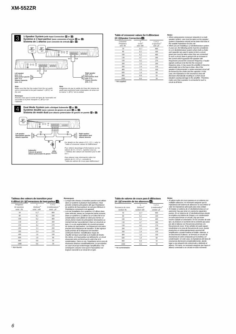
Table of crossover values for 6 dB/octave(4 Ω)(Speaker Connections 4)
L(coil)*
unit: mH
12.7
8.2
6.2
4.7
4.2
3.3
2.4
1.6
1.0
0.8
0.6
C1/C2(capacitor)*
unit: µF
800
500
400
300
270
200
150
100
68
50
39
Notes• When using passive crossover networks in a multi-
speaker system, care must be taken as the speakersystem’s impedance should not be lower than that ofthe suitable impedance for this unit.
• When you are installing a 12 decibels/octave systemin your car, the following points must be considered.In a 12 decibels/octave system where both a chokeand capacitor are used in series to form a circuit,great care must be taken when they are connected.In such a circuit, there is going to be an increase inthe current which bypasses the speaker withfrequencies around the crossover frequency. If audiosignals continue to be fed into the crossoverfrequency area, it may cause the amplifier to becomeabnormally hot or the fuse to blow. Also if thespeaker is disconnected, a series-resonant circuit willbe formed by the choke and the capacitor. In thiscase, the impedance in the resonance area willdecrease dramatically resulting in a short circuitsituation causing damage to the amplifier. Therefore,make sure that a speaker is connected to such acircuit at all times.
Fréquencede transition
unité : Hz
50
80
100
130
150
200
260
400
600
800
1000
* Non fournis
Tableau des valeurs de transition pour6 dB/oct (4 Ω)(Connexions de haut-parleur 4)
L(bobine) *
unité : mH
12,7
8,2
6,2
4,7
4,2
3,3
2,4
1,6
1,0
0,8
0,6
C1/C2(condensateur) *
unité : µF
800
500
400
300
270
200
150
100
68
50
39
Remarques• Lorsque des réseaux à transition passive sont utilisés
dans un système à plusieurs haut-parleurs, il fautprendre certaines précautions afin que l’impédancedu système de haut-parleurs ne soit pas inférieure àl’impédance convenant à cet appareil.
• Lors de l’installation d’un système à 12 dB/oct dansvotre véhicule, prenez en compte les points suivants.Dans un système à 12 dB/oct où un volet d’air et uncondensateur sont utilisés en série pour former uncircuit, prenez toutes les précautions nécessaires aumoment de leur raccordement. Dans un circuit de cetype, il y a une augmentation du courant qui passeau niveau du haut-parleur. Les fréquences sont alorsproches de la fréquence de transition. Si des signauxaudio proches de la fréquence de transitioncontinuent d’arriver, l’amplificateur risque dechauffer de façon anormale ou le fusible de fondre.De même, si le haut-parleur est débranché, un circuitrésonnant série est formé par le volet d’air et lecondensateur. Dans ce cas, l’impédance de la zone derésonance diminue considérablement, ce qui entraîneun court-circuit qui endommage l’amplificateur. Parconséquent, assurez-vous que le haut-parleur esttoujours raccordé à un circuit de ce type.
Tabla de valores de cruce para 6 dB/octava(4 Ω)(Conexión de los altavoces 4)
Frecuencia de cruceunidad: Hz
50
80
100
130
150
200
260
400
600
800
1000
* No suministrados
L(bobina)*
unidad: mH
12,7
8,2
6,2
4,7
4,2
3,3
2,4
1,6
1,0
0,8
0,6
C1/C2(condensador)*
unidad: µF
800
500
400
300
270
200
150
100
68
50
39
Notas• Al utilizar redes de cruce pasivas en un sistema con
múltiples altavoces, es necesario asegurar que laimpedancia del sistema de altavoces no sea inferior alvalor de impedancia adecuado para esta unidad.
• Al instalar un sistema de 12 decibelios/octava en unautomóvil, hay que tener en cuenta los siguientespuntos. En un sistema de 12 decibelios/octava dondese emplea una bobina de choque y un condensadoren serie para formar un circuito, hay que tenermucho cuidado al conectarlos. En los circuitos de estetipo, se produce un aumento de la corriente que pasapor alto el altavoz con frecuencias próximas a lafrecuencia de cruce. Si las señales de audio siguenenviándose a la zona de frecuencia de cruce, puedeproducirse un sobrecalentamiento anormal delamplificador o puede fundirse el fusible. Además, sise desconecta el altavoz, se formará un circuito deresonancia en serie compuesto por la bobina y elcondensador. En este caso, la impedancia del área deresonancia disminuirá considerablemente, dandolugar a una situación de cortocircuito y dañando elaltavoz. Por tanto, es necesario asegurar que haya unaltavoz conectado a un circuito en todo momento.
1-Speaker System (with Input Connection B or D)Système à 1 haut-parleur (avec connexion d’entrée B ou D)Sistema de 1 altavoz (con conexión de entrada B o D)
33333
Dual Mode System (with a Bridged Subwoofer A or C)Système double (avec caisson de graves en pont A ou C)Sistema de modo dual (con altavoz potenciador de graves en puente A o C)
44444
(80Hz)
OFF ON
LPF (80Hz)
OFF ON
LPF
BTLBTL
BTLBTL
NoteMake sure that the line output from the car audiounit is connected to the jack marked “L (BTL)” onthe unit.
RemarqueAssurez-vous que la sortie de ligne de l’autoradio estraccordée à la prise marquée «L (BTL)» surl’appareil.
Right speaker(min. 4 Ω)Haut-parleur droit(min. 4 Ω)Altavoz derecho(mín. 4 Ω)
Left speaker(min. 4 Ω)Haut-parleur gauche(min. 4 Ω)Altavoz izquierdo(mín. 4 Ω)
NotaAsegúrese de que la salida de línea del sistema deaudio para automóvil está conectada a la toma conla marca “L (BTL)” de la unidad.
(80Hz)
OFF ON
LPF
C1 C2
L
SubwooferCaisson de gravesAltavoz potenciador de graves
Left speakerHaut-parleur gaucheAltavoz izquierdo
Right speakerHaut-parleur droitAltavoz derecho
For details on the values of C1, C2, L, refer to“Table of crossover values for 6dB/octave”.
Pour obtenir davantage d’informations sur lesvaleurs de C1, C2 et L, reportez-vous au« Tableau des valeurs de transition pour 6 dB/oct ».
Para obtener más información sobre losvalores de C1, C2 y L, consulte la“Tabla de valores de cruce para 6dB/octava”.
7
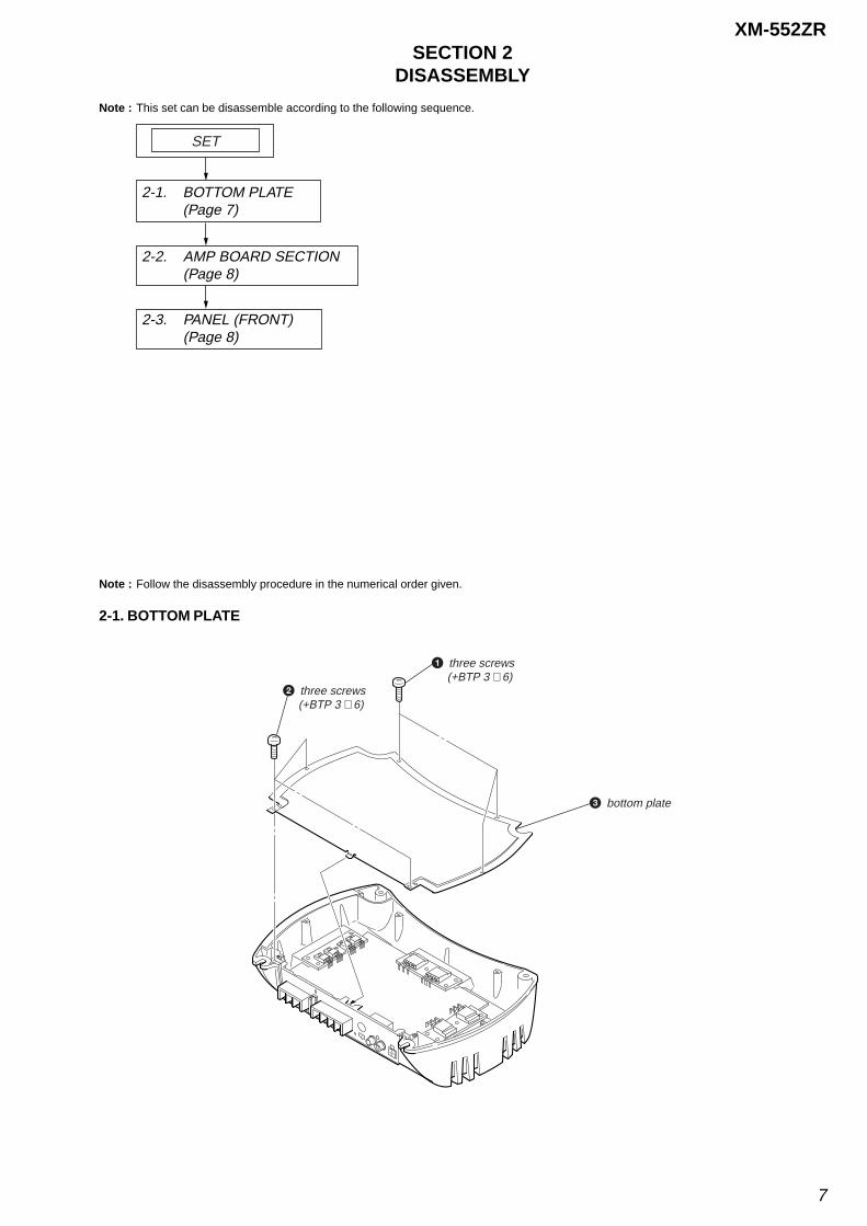
XM-552ZRSECTION 2
DISASSEMBLY
Note : This set can be disassemble according to the following sequence.
Note : Follow the disassembly procedure in the numerical order given.
2-1. BOTTOM PLATE
1 three screws (+BTP 3 × 6)
3 bottom plate
2 three screws (+BTP 3 × 6)
2-1. BOTTOM PLATE(Page 7)
2-2. AMP BOARD SECTION (Page 8)
SET
2-3. PANEL (FRONT) (Page 8)
8
XM-552ZR
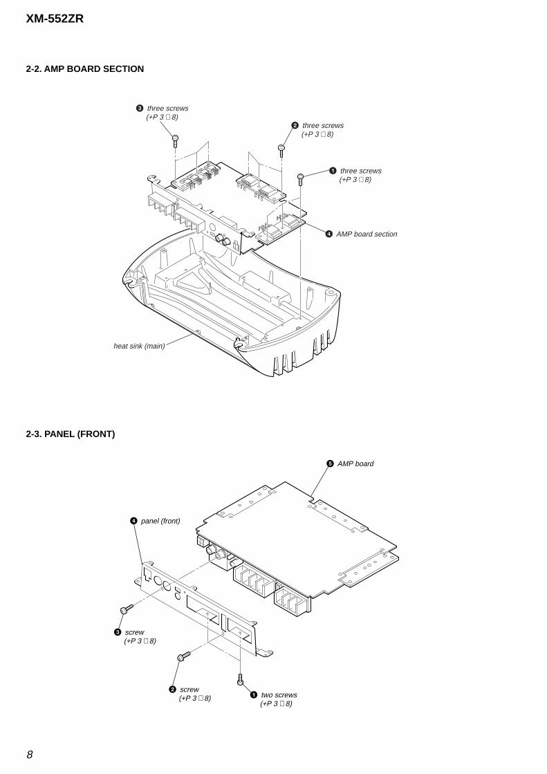
2-2. AMP BOARD SECTION
2-3. PANEL (FRONT)
1 three screws (+P 3 × 8)
2 three screws (+P 3 × 8)
3 three screws (+P 3 × 8)
4 AMP board section
heat sink (main)
1 two screws (+P 3 × 8)
2 screw (+P 3 × 8)
3 screw (+P 3 × 8)
4 panel (front)
5 AMP board
9 9
XM-552ZR
XM-552ZR
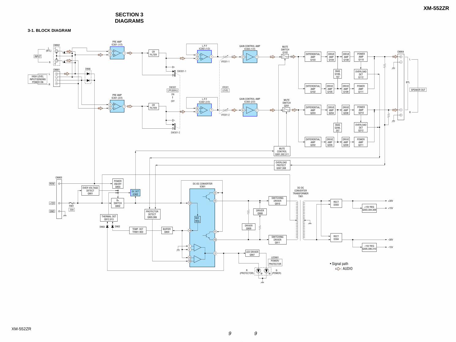
SECTION 3DIAGRAMS
3-1. BLOCK DIAGRAM
23
PRE AMPIC301 (1/2)
23
L.P.FIC302 (1/2)
DIFFERENTIALAMPQ103
POWERAMPQ110
OVERLOADDETQ112
DRIVEAMPQ104
DRIVEAMPQ108
DIFFERENTIALAMPQ102
POWERAMPQ111
DRIVEAMPQ105
DRIVEAMPQ109
BIASQ206,207
CN902
D906
INPUT
L(BTL)
SPEAKER OUT
L
R
MUTESWITCH
Q102
REM
+12V
GND
9
DIFFERENTIALAMPQ203
POWERAMPQ210
OVERLOADDETQ212
DRIVEAMPQ204
DRIVEAMPQ208
DIFFERENTIALAMPQ202
POWERON/OFFQ903
MUTECONTROL
Q301,302,311
POWERAMPQ211
DRIVEAMPQ205
DRIVEAMPQ209
CN901
LHIGH LEVEL
INPUT/SENSINGPOWER ON
R
MUTESWITCH
Q201
OVERLOADPROTECTQ307,308
1516
12
14
12B+
SWITCHQ902
OVER VOLTAGEDETECT
Q901DC DETIC902
REF.REG
TEMP. DETTH901-903
BUFFERQ904
THERMAL DETQ912,913
CN903
F901
RECTD303
RECTD304
+15V
+30VSWITCHING
DRIVERQ910
SWITCHINGDRIVER
Q911
DRIVERQ909
PROTECTORDETECT
Q905,906
DRIVERQ908
8
10
3
11
LED901POWER/
PROTECTOR
DC-DCCONVERTER
TRANSFORMERT901
DC-DC CONVERTERIC901
D902D903
• Signal path : AUDIO
CN904
BTL
-1
-2
LED DRIVERQ907
R(PROTECTOR)
G(POWER)
R
11 CR
FILTER
ON
OFF
SW301-1
VR301-1
SW301LPF(80Hz)
30A
VR301LEVEL
2 1
GAIN CONTROL AMPIC303 (1/2)
GAIN CONTROL AMPIC303 (2/2)
5
PRE AMPIC301 (2/2)
65
L.P.FIC302 (2/2)
77 CR
FILTER
SW301-2
VR301-2
6 76
+15V REGQ303,304,309
–15V
–30V
–15V REGQ305,306,310
BIASQ106,107
10 10
XM-552ZR
XM-552ZR
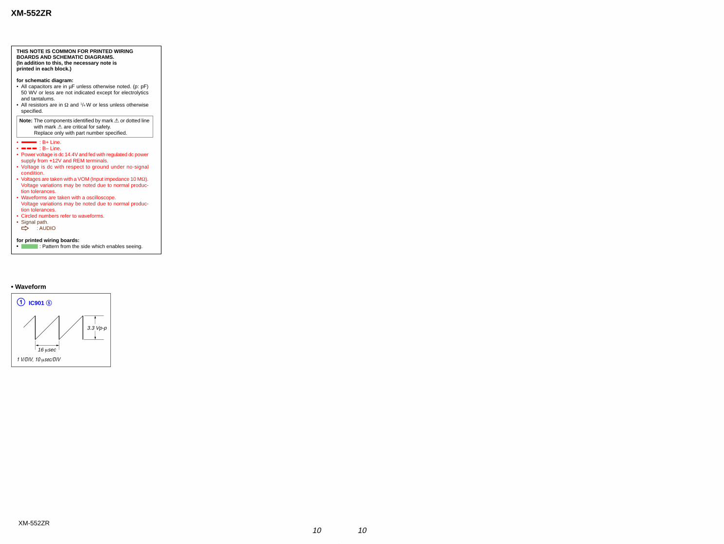
THIS NOTE IS COMMON FOR PRINTED WIRINGBOARDS AND SCHEMATIC DIAGRAMS.(In addition to this, the necessary note isprinted in each block.)
for schematic diagram:• All capacitors are in µF unless otherwise noted. (p: pF)
50 WV or less are not indicated except for electrolyticsand tantalums.
• All resistors are in Ω and 1/4 W or less unless otherwise
specified.
• A : B+ Line.• B : B– Line.• Power voltage is dc 14.4V and fed with regulated dc power
supply from +12V and REM terminals.• Voltage is dc with respect to ground under no-signal
condition.• Voltages are taken with a VOM (Input impedance 10 MΩ).
Voltage variations may be noted due to normal produc-tion tolerances.
• Waveforms are taken with a oscilloscope.Voltage variations may be noted due to normal produc-tion tolerances.
• Circled numbers refer to waveforms.• Signal path.
F : AUDIO
for printed wiring boards:• : Pattern from the side which enables seeing.
Note: The components identified by mark 0 or dotted linewith mark 0 are critical for safety.Replace only with part number specified.
• Waveform
1 V/DIV, 10 µsec/DIV
1 IC901 5
3.3 Vp-p
16 µsec
11 11
XM-552ZR
XM-552ZR
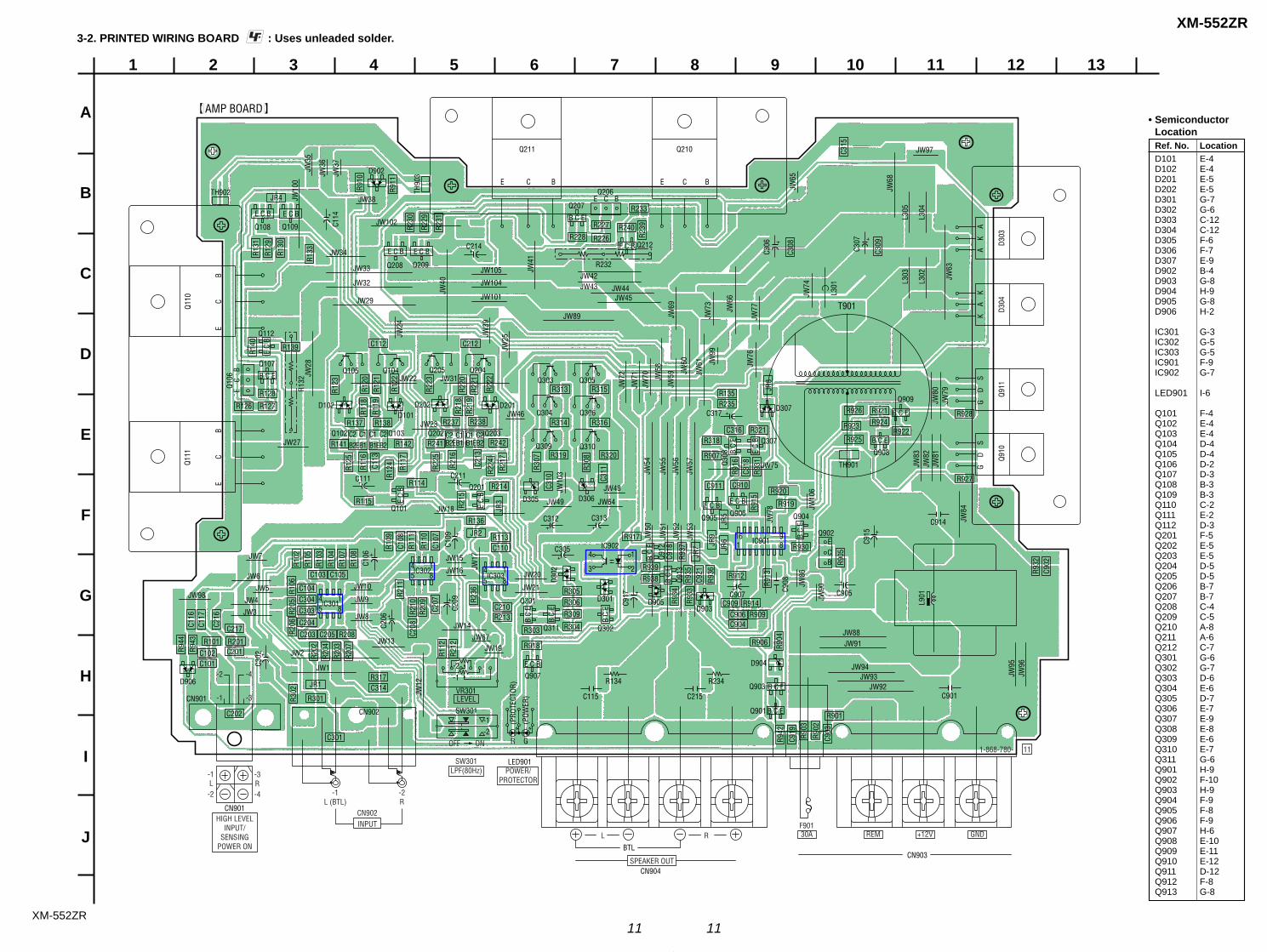
3-2. PRINTED WIRING BOARD : Uses unleaded solder.
1
A
B
C
D
E
F
G
H
I
J
2 3 4 5 6 7 8 9 10 11 12 13
E C
B
Q108 Q109
Q204Q205Q104Q105
Q304
Q309 Q310
Q306
Q303 Q305
C302
C111
C312 C313
C305
C905
C317D307
C907
IC902
C215C115
R134 R234
C914
C901
JW88
JW94JW93
JW91
JW92
JW95
JW96
C306
C307
T901
JW54
JW78
JW53
JW52
JW51
JW50
JW55
JW56
JW57
JW72
JW71
JW70 JW
58
D302
C917
C915
AMP BOARD
Q101
Q907
Q301
Q311
D301
Q302JW14JW67
JW19
D102
Q112
Q107
Q211 Q210
D303
D304
Q911
Q910
JW97
D101D202
Q202 Q203Q102 Q103
D201
IC301
IC302IC303
D904
D903
Q903
Q901
D905
IC901
D902
R131
R130
R133
JR4R233
R227
R226R240
R228
C315
C308
C309
R239R2
31
R229
R230
R910
R911
R127
R128
R139 C212C112
R126
R122
R223
R123
R220
R221
R222
R121
R120
R140
R125
R116
R225
R102
R103
R104
R107
R108
C206
C106
C209
R105
R205
R106
R236
R206
R202
R204
R203
R207
R302
R944
R943
C116
C117
C216
R211
R109
C108
R111
R110
C107
C207
R210
C208
R112
JW12
R212
R209
R216
R307
C310 C3
11R308
R217C213
R224
R215
C109
JR3
JW17
JW10
3
R137 R138
R142R141
R214
JR2
R136
C101C102
R101 R201
C217
C201
D906
R208C205C203
C204
C303C304C104
C103 C105
JR1
R301
R317C314
C301
CN902
CN901
C202
R918
R303
R917
R933
R904
R902
C903
R903
C919
R942
C909
R912
R914
R906
R901
R909C906C904
C902
R932
R934
R913
C908 JW
86
JW90
C918
Q912
Q913
R937
JR7 JR
9
JR6
JR5
R936
C921
R935
R916Q3
08
C318
R931
R915
R905
JR8
JW80
JW10
6
JW79
JW83
JW82
JW81
JW84
R938R939
R927
R922
R921R924
R926 R928
R920
Q902
R919
Q904
R930
R321C316
R135R235
R318
R907
C910C911
R925
R923
R305R306
R304
R309
C110R113
R213C210
R314 R316
R319 R320
R313 R315
R238
R242
R237
R114
R241
R115
R118
R119
C113
R124 R1
17
R218
R219
R129
JW37
JW36
JW35
C114
JW10
0
JW41
JW40
JW59 JW
60
JW61 JW
99
JW76
L301 L3
03
L302
L305
JW68
JW63
L304
JW65
JW24
JW28
JW27
JW21
JW20
JW10
JW7
JW13
JW5
JW6
JW15
JW49
JW46JW23
JW18
C211
JW31JW22
JW48
JW75
JW64
JW16
JW4
JW3
JW2
JW1
JW98 JW9
JW8
VR301
-1
-2
LEVEL
SW301
LED901
JW39
JW25
JW69
JW73 JW
66
JW77
JW74
R232JW33
JW32
JW29
JW105
C214
JW102
JW104
JW101 JW45JW44
JW42JW43
JW89
JW34
JW38Q207
Q206
Q212
TH901
L901
Q908
Q909
Q307
Q905 Q906
TH902
C2 C1B2 B1E
C1 C2B1 B2E
C2 C1B2 B1E
C1 C2B1 B2E
TH90
3
Q110
Q106
R132
REM +12V GND
-2 -4
-1 -3
INPUTCN902
SPEAKER OUT
-1L (BTL)
-2R
L R
POWER/PROTECTOR
OFF ON
SW301LPF(80Hz)
-1
R G
(PRO
TECT
OR)
(POW
ER)
-2
CN904
BTLCN903
30AF901
111-868-780-
B C E
BCE
E C B
BCE
BCE
B C E
E C
B
E C B E C B
E C B E C B
Q208 Q209
E C
B
1485
1485
1485
BC
E
Q111
BC
E
BC
E
ECB
4
3
1
2
E C B
B C
E
B C
E
B C
E
B C E
B C E
B C
E
B C
E
E C
B
1 816 9
B C E
E C B
B C
E
B C
E
E C BD305
Q201D306
HIGH LEVELINPUT/
SENSINGPOWER ON
-1 -3
-2 -4L R
CN901
B C E
A
K
AK
A
K
G
D
SG
D
S
Ref. No. LocationD101 E-4D102 E-4D201 E-5D202 E-5D301 G-7D302 G-6D303 C-12D304 C-12D305 F-6D306 F-7D307 E-9D902 B-4D903 G-8D904 H-9D905 G-8D906 H-2
IC301 G-3IC302 G-5IC303 G-5IC901 F-9IC902 G-7
LED901 I-6
Q101 F-4Q102 E-4Q103 E-4Q104 D-4Q105 D-4Q106 D-2Q107 D-3Q108 B-3Q109 B-3Q110 C-2Q111 E-2Q112 D-3Q201 F-5Q202 E-5Q203 E-5Q204 D-5Q205 D-5Q206 B-7Q207 B-7Q208 C-4Q209 C-5Q210 A-8Q211 A-6Q212 C-7Q301 G-6Q302 G-7Q303 D-6Q304 E-6Q305 D-7Q306 E-7Q307 E-9Q308 E-8Q309 E-6Q310 E-7Q311 G-6Q901 H-9Q902 F-10Q903 H-9Q904 F-9Q905 F-8Q906 F-9Q907 H-6Q908 E-10Q909 E-11Q910 E-12Q911 D-12Q912 F-8Q913 G-8
• SemiconductorLocation
12 12
XM-552ZR
XM-552ZR
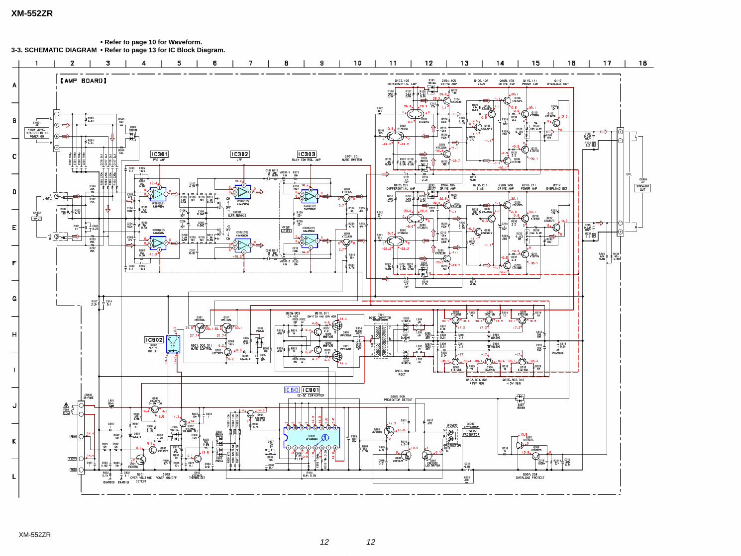
• Refer to page 10 for Waveform.3-3. SCHEMATIC DIAGRAM • Refer to page 13 for IC Block Diagram.
IC B/D
C103
C203
R202
R133
R233
R901 R902
R903
C909
F901
C102
C101
C202
C201
R101
R201
C302 R302
R301 C301
R102
R103
R203
C104
C105C303
C106
R109
C206
R209 R210
C204
C205C304
C109
C110
C209
R114
R214
R123
R125
R124
R122
R127
C114
R129
R130
R132
R223
R225
R224
R222
R227
R231
R229
C214R230
R232 R234
R932 C902
R904R906
C904
R915
R916
C911
C906 C908 C318
R927
R928
R922
R924
R921
R923
R919
R920
C915
C306
C307
R307
R308
C308 C310
C311
R313 R314 R319
C312
R315 R316 R320
C313
R318
C316 C317
R931
R306
C314R317
C315
C907
R912
R304
R110
R116
R131
R134
R216
C905
C210
C903
C107
C207
C108
C208
R113
R213
Q101
Q201
R309
R303
R142
R141
R242
R241
Q102
Q202
Q103
Q203
Q104
Q204
Q105
Q205
Q108
Q208
Q110
Q210
Q109
Q209
Q111
Q211
R117
R217
C111
C211
Q301 Q311
C305
Q910
Q911
Q908
Q909
T901D303
D304
Q303 Q304 Q309
Q305 Q306 Q310
L901
C116
C117
R943
R944
C919
R942
Q901
Q905
Q906
Q902
R939
C917
R934
C921
R938
R937 C918
R933
R930R917
R918
R10
4
R10
5R
204
R20
5
R136
R236
R140
R240
R321C901
C910
CN901
CN902
L304
L305
L302
L303
SW301
VR301
VR301
CN904
CN903
TH90
1
TH90
2
TH90
3
D906
C216
C217
R107
R106IC301(1/2)
IC301(2/2)
R206
R207
R208 R211
R108 R111IC302(1/2)
IC302(2/2)
R112
R212
IC303(1/2)
IC303(2/2)
R118 R121 R138
D101
R126
D102R119R137R120
R128 Q107
Q106 R139
C115
C215
R235 R135
Q212
R239
Q207
Q206
R228
R226
D201
R238R221R218
D202R219R237R220
IC902
Q302
R305
D301
D302 C914
L301
C309
D305
D306
D307
Q307
Q308
LED901
Q907
R907
IC901
R91
3
R914
Q904
D902
D903
Q912
Q913
Q903
R905
D904
R115
R215
C112
C113
Q112
C212
C213
R925
R926
R936
R935
D905
R90
9
R91
0
R91
1
13
XM-552ZR
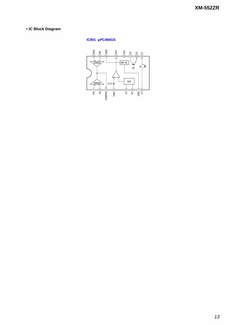
• IC Block Diagram
IC901 µPC494GS
OSC
REF 5V
ERROR
ERROR
0.1V
Q1Q2
16 15 14 13 12 11 10 9
1 2 3 4 5 6 7 8
NON
INV
VREF
VCC
C2 E1E2OUT
+IN -IN
COM
PEN CT RT C1
GND
TIM
E
14
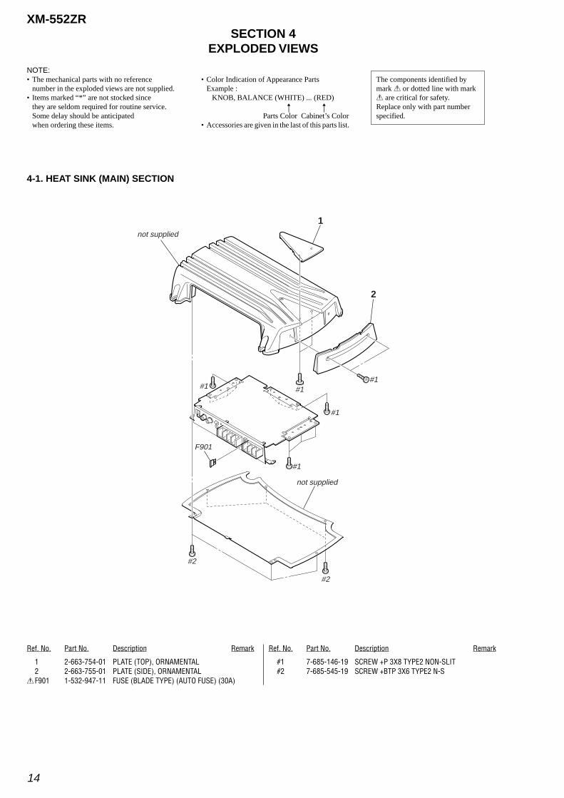
XM-552ZRSECTION 4
EXPLODED VIEWS
NOTE:• The mechanical parts with no reference
number in the exploded views are not supplied.• Items marked “*” are not stocked since
they are seldom required for routine service.Some delay should be anticipatedwhen ordering these items.
• Color Indication of Appearance PartsExample :
KNOB, BALANCE (WHITE) ... (RED)
Parts Color Cabinet’s Color• Accessories are given in the last of this parts list.
The components identified bymark 0 or dotted line with mark0 are critical for safety.Replace only with part numberspecified.
Ref. No. Part No. Description Remark
4-1. HEAT SINK (MAIN) SECTION
R
Ref. No. Part No. Description Remark
R
1 2-663-754-01 PLATE (TOP), ORNAMENTAL2 2-663-755-01 PLATE (SIDE), ORNAMENTAL
0F901 1-532-947-11 FUSE (BLADE TYPE) (AUTO FUSE) (30A)
#1 7-685-146-19 SCREW +P 3X8 TYPE2 NON-SLIT#2 7-685-545-19 SCREW +BTP 3X6 TYPE2 N-S
F901
not supplied
not supplied
#1#1
#1
#1
#1
#2
#2
1
2
15
XM-552ZR
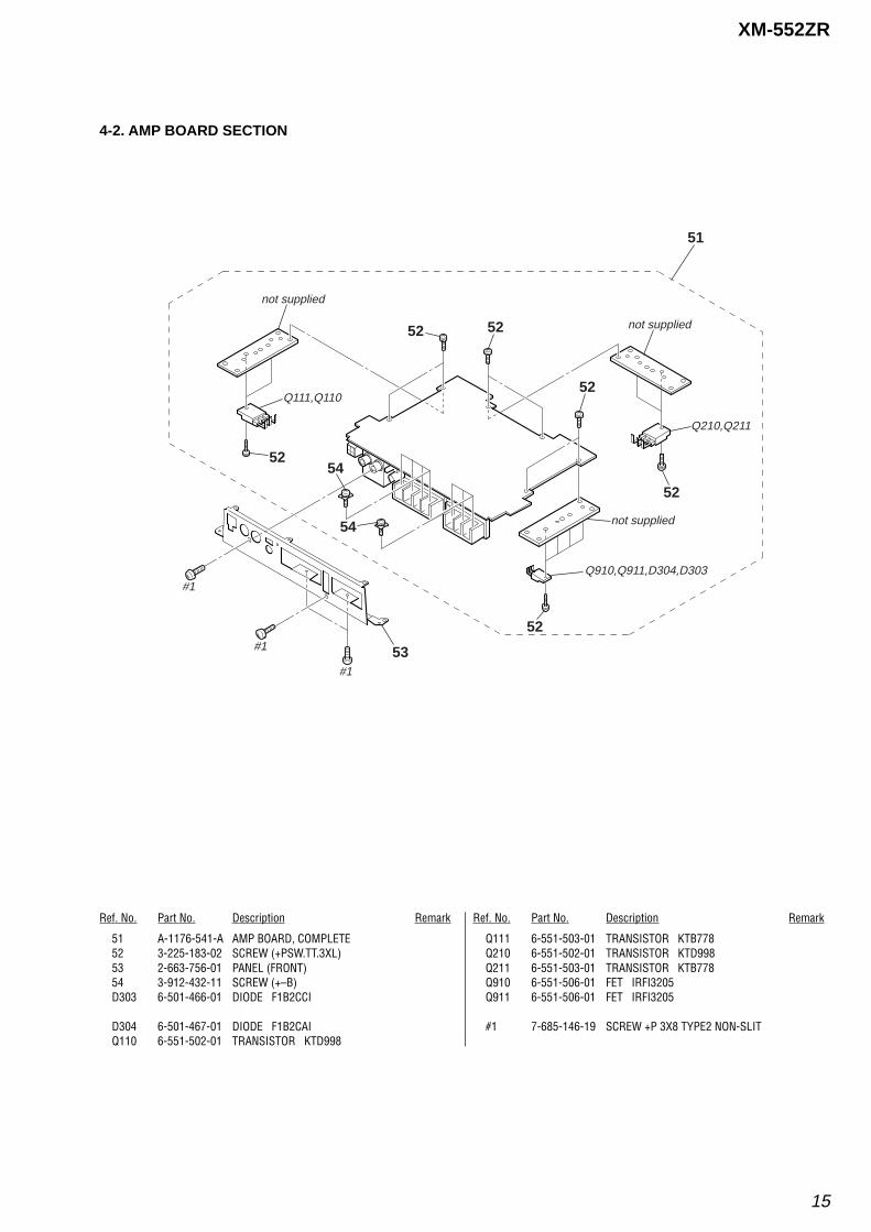
4-2. AMP BOARD SECTION
Ref. No. Part No. Description RemarkRef. No. Part No. Description Remark
51 A-1176-541-A AMP BOARD, COMPLETE52 3-225-183-02 SCREW (+PSW.TT.3XL)53 2-663-756-01 PANEL (FRONT)54 3-912-432-11 SCREW (+–B)D303 6-501-466-01 DIODE F1B2CCI
D304 6-501-467-01 DIODE F1B2CAIQ110 6-551-502-01 TRANSISTOR KTD998
Q111 6-551-503-01 TRANSISTOR KTB778Q210 6-551-502-01 TRANSISTOR KTD998Q211 6-551-503-01 TRANSISTOR KTB778Q910 6-551-506-01 FET IRFI3205Q911 6-551-506-01 FET IRFI3205
#1 7-685-146-19 SCREW +P 3X8 TYPE2 NON-SLIT
#1
#1
#1
51
52
52
52 52
52
52
53
54
54
not supplied
Q910,Q911,D304,D303
Q210,Q211
Q111,Q110
not supplied
not supplied
16
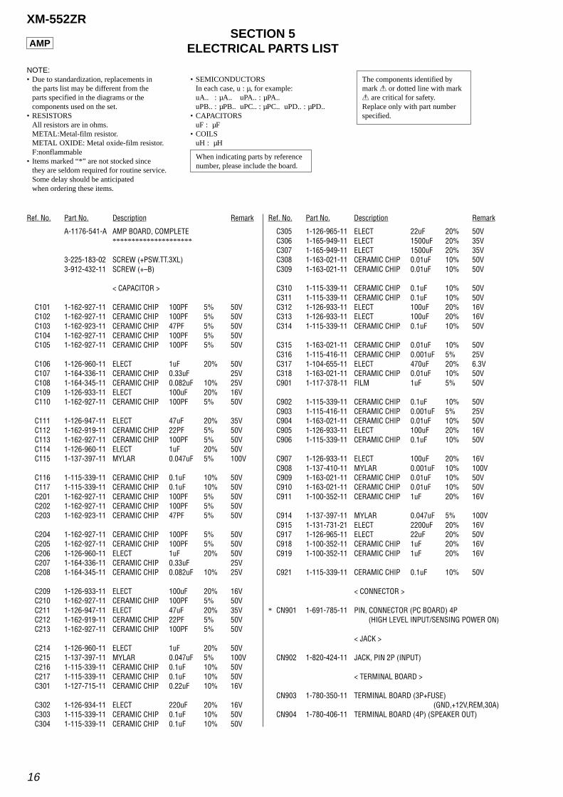
XM-552ZRSECTION 5
ELECTRICAL PARTS LIST
Ref. No. Part No. Description Remark Ref. No. Part No. Description Remark
NOTE:• Due to standardization, replacements in
the parts list may be different from theparts specified in the diagrams or thecomponents used on the set.
• RESISTORSAll resistors are in ohms.METAL:Metal-film resistor.METAL OXIDE: Metal oxide-film resistor.F:nonflammable
• Items marked “*” are not stocked sincethey are seldom required for routine service.Some delay should be anticipatedwhen ordering these items.
• SEMICONDUCTORSIn each case, u : µ, for example:uA.. : µA.. uPA.. : µPA..uPB.. : µPB.. uPC.. : µPC.. uPD.. : µPD..
• CAPACITORSuF : µF
• COILSuH : µH
A-1176-541-A AMP BOARD, COMPLETE*********************
3-225-183-02 SCREW (+PSW.TT.3XL)3-912-432-11 SCREW (+–B)
< CAPACITOR >
C101 1-162-927-11 CERAMIC CHIP 100PF 5% 50VC102 1-162-927-11 CERAMIC CHIP 100PF 5% 50VC103 1-162-923-11 CERAMIC CHIP 47PF 5% 50VC104 1-162-927-11 CERAMIC CHIP 100PF 5% 50VC105 1-162-927-11 CERAMIC CHIP 100PF 5% 50V
C106 1-126-960-11 ELECT 1uF 20% 50VC107 1-164-336-11 CERAMIC CHIP 0.33uF 25VC108 1-164-345-11 CERAMIC CHIP 0.082uF 10% 25VC109 1-126-933-11 ELECT 100uF 20% 16VC110 1-162-927-11 CERAMIC CHIP 100PF 5% 50V
C111 1-126-947-11 ELECT 47uF 20% 35VC112 1-162-919-11 CERAMIC CHIP 22PF 5% 50VC113 1-162-927-11 CERAMIC CHIP 100PF 5% 50VC114 1-126-960-11 ELECT 1uF 20% 50VC115 1-137-397-11 MYLAR 0.047uF 5% 100V
C116 1-115-339-11 CERAMIC CHIP 0.1uF 10% 50VC117 1-115-339-11 CERAMIC CHIP 0.1uF 10% 50VC201 1-162-927-11 CERAMIC CHIP 100PF 5% 50VC202 1-162-927-11 CERAMIC CHIP 100PF 5% 50VC203 1-162-923-11 CERAMIC CHIP 47PF 5% 50V
C204 1-162-927-11 CERAMIC CHIP 100PF 5% 50VC205 1-162-927-11 CERAMIC CHIP 100PF 5% 50VC206 1-126-960-11 ELECT 1uF 20% 50VC207 1-164-336-11 CERAMIC CHIP 0.33uF 25VC208 1-164-345-11 CERAMIC CHIP 0.082uF 10% 25V
C209 1-126-933-11 ELECT 100uF 20% 16VC210 1-162-927-11 CERAMIC CHIP 100PF 5% 50VC211 1-126-947-11 ELECT 47uF 20% 35VC212 1-162-919-11 CERAMIC CHIP 22PF 5% 50VC213 1-162-927-11 CERAMIC CHIP 100PF 5% 50V
C214 1-126-960-11 ELECT 1uF 20% 50VC215 1-137-397-11 MYLAR 0.047uF 5% 100VC216 1-115-339-11 CERAMIC CHIP 0.1uF 10% 50VC217 1-115-339-11 CERAMIC CHIP 0.1uF 10% 50VC301 1-127-715-11 CERAMIC CHIP 0.22uF 10% 16V
C302 1-126-934-11 ELECT 220uF 20% 16VC303 1-115-339-11 CERAMIC CHIP 0.1uF 10% 50VC304 1-115-339-11 CERAMIC CHIP 0.1uF 10% 50V
C305 1-126-965-11 ELECT 22uF 20% 50VC306 1-165-949-11 ELECT 1500uF 20% 35VC307 1-165-949-11 ELECT 1500uF 20% 35VC308 1-163-021-11 CERAMIC CHIP 0.01uF 10% 50VC309 1-163-021-11 CERAMIC CHIP 0.01uF 10% 50V
C310 1-115-339-11 CERAMIC CHIP 0.1uF 10% 50VC311 1-115-339-11 CERAMIC CHIP 0.1uF 10% 50VC312 1-126-933-11 ELECT 100uF 20% 16VC313 1-126-933-11 ELECT 100uF 20% 16VC314 1-115-339-11 CERAMIC CHIP 0.1uF 10% 50V
C315 1-163-021-11 CERAMIC CHIP 0.01uF 10% 50VC316 1-115-416-11 CERAMIC CHIP 0.001uF 5% 25VC317 1-104-655-11 ELECT 470uF 20% 6.3VC318 1-163-021-11 CERAMIC CHIP 0.01uF 10% 50VC901 1-117-378-11 FILM 1uF 5% 50V
C902 1-115-339-11 CERAMIC CHIP 0.1uF 10% 50VC903 1-115-416-11 CERAMIC CHIP 0.001uF 5% 25VC904 1-163-021-11 CERAMIC CHIP 0.01uF 10% 50VC905 1-126-933-11 ELECT 100uF 20% 16VC906 1-115-339-11 CERAMIC CHIP 0.1uF 10% 50V
C907 1-126-933-11 ELECT 100uF 20% 16VC908 1-137-410-11 MYLAR 0.001uF 10% 100VC909 1-163-021-11 CERAMIC CHIP 0.01uF 10% 50VC910 1-163-021-11 CERAMIC CHIP 0.01uF 10% 50VC911 1-100-352-11 CERAMIC CHIP 1uF 20% 16V
C914 1-137-397-11 MYLAR 0.047uF 5% 100VC915 1-131-731-21 ELECT 2200uF 20% 16VC917 1-126-965-11 ELECT 22uF 20% 50VC918 1-100-352-11 CERAMIC CHIP 1uF 20% 16VC919 1-100-352-11 CERAMIC CHIP 1uF 20% 16V
C921 1-115-339-11 CERAMIC CHIP 0.1uF 10% 50V
< CONNECTOR >
* CN901 1-691-785-11 PIN, CONNECTOR (PC BOARD) 4P(HIGH LEVEL INPUT/SENSING POWER ON)
< JACK >
CN902 1-820-424-11 JACK, PIN 2P (INPUT)
< TERMINAL BOARD >
CN903 1-780-350-11 TERMINAL BOARD (3P+FUSE)(GND,+12V,REM,30A)
CN904 1-780-406-11 TERMINAL BOARD (4P) (SPEAKER OUT)
The components identified bymark 0 or dotted line with mark0 are critical for safety.Replace only with part numberspecified.
When indicating parts by referencenumber, please include the board.
AMP
17
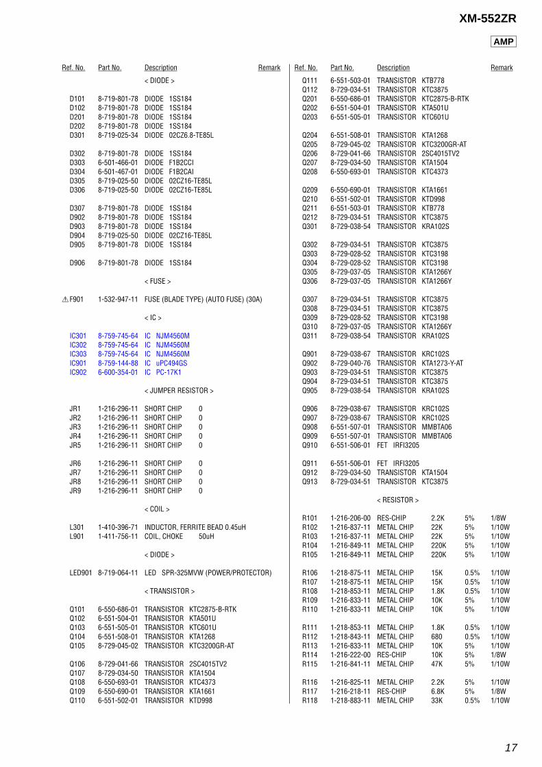
XM-552ZR
Ref. No. Part No. Description Remark Ref. No. Part No. Description Remark
< DIODE >
D101 8-719-801-78 DIODE 1SS184D102 8-719-801-78 DIODE 1SS184D201 8-719-801-78 DIODE 1SS184D202 8-719-801-78 DIODE 1SS184D301 8-719-025-34 DIODE 02CZ6.8-TE85L
D302 8-719-801-78 DIODE 1SS184D303 6-501-466-01 DIODE F1B2CCID304 6-501-467-01 DIODE F1B2CAID305 8-719-025-50 DIODE 02CZ16-TE85LD306 8-719-025-50 DIODE 02CZ16-TE85L
D307 8-719-801-78 DIODE 1SS184D902 8-719-801-78 DIODE 1SS184D903 8-719-801-78 DIODE 1SS184D904 8-719-025-50 DIODE 02CZ16-TE85LD905 8-719-801-78 DIODE 1SS184
D906 8-719-801-78 DIODE 1SS184
< FUSE >
0F901 1-532-947-11 FUSE (BLADE TYPE) (AUTO FUSE) (30A)
< IC >
IC301 8-759-745-64 IC NJM4560MIC302 8-759-745-64 IC NJM4560MIC303 8-759-745-64 IC NJM4560MIC901 8-759-144-88 IC uPC494GSIC902 6-600-354-01 IC PC-17K1
< JUMPER RESISTOR >
JR1 1-216-296-11 SHORT CHIP 0JR2 1-216-296-11 SHORT CHIP 0JR3 1-216-296-11 SHORT CHIP 0JR4 1-216-296-11 SHORT CHIP 0JR5 1-216-296-11 SHORT CHIP 0
JR6 1-216-296-11 SHORT CHIP 0JR7 1-216-296-11 SHORT CHIP 0JR8 1-216-296-11 SHORT CHIP 0JR9 1-216-296-11 SHORT CHIP 0
< COIL >
L301 1-410-396-71 INDUCTOR, FERRITE BEAD 0.45uHL901 1-411-756-11 COIL, CHOKE 50uH
< DIODE >
LED901 8-719-064-11 LED SPR-325MVW (POWER/PROTECTOR)
< TRANSISTOR >
Q101 6-550-686-01 TRANSISTOR KTC2875-B-RTKQ102 6-551-504-01 TRANSISTOR KTA501UQ103 6-551-505-01 TRANSISTOR KTC601UQ104 6-551-508-01 TRANSISTOR KTA1268Q105 8-729-045-02 TRANSISTOR KTC3200GR-AT
Q106 8-729-041-66 TRANSISTOR 2SC4015TV2Q107 8-729-034-50 TRANSISTOR KTA1504Q108 6-550-693-01 TRANSISTOR KTC4373Q109 6-550-690-01 TRANSISTOR KTA1661Q110 6-551-502-01 TRANSISTOR KTD998
Q111 6-551-503-01 TRANSISTOR KTB778Q112 8-729-034-51 TRANSISTOR KTC3875Q201 6-550-686-01 TRANSISTOR KTC2875-B-RTKQ202 6-551-504-01 TRANSISTOR KTA501UQ203 6-551-505-01 TRANSISTOR KTC601U
Q204 6-551-508-01 TRANSISTOR KTA1268Q205 8-729-045-02 TRANSISTOR KTC3200GR-ATQ206 8-729-041-66 TRANSISTOR 2SC4015TV2Q207 8-729-034-50 TRANSISTOR KTA1504Q208 6-550-693-01 TRANSISTOR KTC4373
Q209 6-550-690-01 TRANSISTOR KTA1661Q210 6-551-502-01 TRANSISTOR KTD998Q211 6-551-503-01 TRANSISTOR KTB778Q212 8-729-034-51 TRANSISTOR KTC3875Q301 8-729-038-54 TRANSISTOR KRA102S
Q302 8-729-034-51 TRANSISTOR KTC3875Q303 8-729-028-52 TRANSISTOR KTC3198Q304 8-729-028-52 TRANSISTOR KTC3198Q305 8-729-037-05 TRANSISTOR KTA1266YQ306 8-729-037-05 TRANSISTOR KTA1266Y
Q307 8-729-034-51 TRANSISTOR KTC3875Q308 8-729-034-51 TRANSISTOR KTC3875Q309 8-729-028-52 TRANSISTOR KTC3198Q310 8-729-037-05 TRANSISTOR KTA1266YQ311 8-729-038-54 TRANSISTOR KRA102S
Q901 8-729-038-67 TRANSISTOR KRC102SQ902 8-729-040-76 TRANSISTOR KTA1273-Y-ATQ903 8-729-034-51 TRANSISTOR KTC3875Q904 8-729-034-51 TRANSISTOR KTC3875Q905 8-729-038-54 TRANSISTOR KRA102S
Q906 8-729-038-67 TRANSISTOR KRC102SQ907 8-729-038-67 TRANSISTOR KRC102SQ908 6-551-507-01 TRANSISTOR MMBTA06Q909 6-551-507-01 TRANSISTOR MMBTA06Q910 6-551-506-01 FET IRFI3205
Q911 6-551-506-01 FET IRFI3205Q912 8-729-034-50 TRANSISTOR KTA1504Q913 8-729-034-51 TRANSISTOR KTC3875
< RESISTOR >
R101 1-216-206-00 RES-CHIP 2.2K 5% 1/8WR102 1-216-837-11 METAL CHIP 22K 5% 1/10WR103 1-216-837-11 METAL CHIP 22K 5% 1/10WR104 1-216-849-11 METAL CHIP 220K 5% 1/10WR105 1-216-849-11 METAL CHIP 220K 5% 1/10W
R106 1-218-875-11 METAL CHIP 15K 0.5% 1/10WR107 1-218-875-11 METAL CHIP 15K 0.5% 1/10WR108 1-218-853-11 METAL CHIP 1.8K 0.5% 1/10WR109 1-216-833-11 METAL CHIP 10K 5% 1/10WR110 1-216-833-11 METAL CHIP 10K 5% 1/10W
R111 1-218-853-11 METAL CHIP 1.8K 0.5% 1/10WR112 1-218-843-11 METAL CHIP 680 0.5% 1/10WR113 1-216-833-11 METAL CHIP 10K 5% 1/10WR114 1-216-222-00 RES-CHIP 10K 5% 1/8WR115 1-216-841-11 METAL CHIP 47K 5% 1/10W
R116 1-216-825-11 METAL CHIP 2.2K 5% 1/10WR117 1-216-218-11 RES-CHIP 6.8K 5% 1/8WR118 1-218-883-11 METAL CHIP 33K 0.5% 1/10W
AMP
18
XM-552ZR
Ref. No. Part No. Description Remark Ref. No. Part No. Description Remark
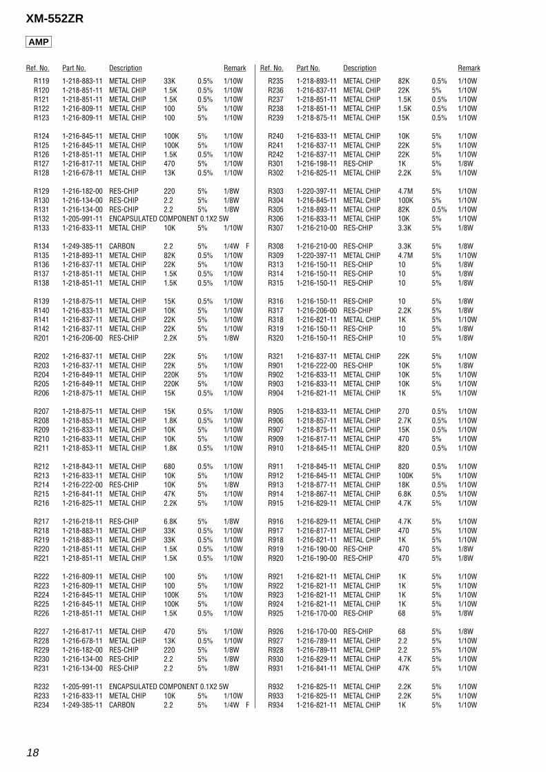
R119 1-218-883-11 METAL CHIP 33K 0.5% 1/10WR120 1-218-851-11 METAL CHIP 1.5K 0.5% 1/10WR121 1-218-851-11 METAL CHIP 1.5K 0.5% 1/10WR122 1-216-809-11 METAL CHIP 100 5% 1/10WR123 1-216-809-11 METAL CHIP 100 5% 1/10W
R124 1-216-845-11 METAL CHIP 100K 5% 1/10WR125 1-216-845-11 METAL CHIP 100K 5% 1/10WR126 1-218-851-11 METAL CHIP 1.5K 0.5% 1/10WR127 1-216-817-11 METAL CHIP 470 5% 1/10WR128 1-216-678-11 METAL CHIP 13K 0.5% 1/10W
R129 1-216-182-00 RES-CHIP 220 5% 1/8WR130 1-216-134-00 RES-CHIP 2.2 5% 1/8WR131 1-216-134-00 RES-CHIP 2.2 5% 1/8WR132 1-205-991-11 ENCAPSULATED COMPONENT 0.1X2 5WR133 1-216-833-11 METAL CHIP 10K 5% 1/10W
R134 1-249-385-11 CARBON 2.2 5% 1/4W FR135 1-218-893-11 METAL CHIP 82K 0.5% 1/10WR136 1-216-837-11 METAL CHIP 22K 5% 1/10WR137 1-218-851-11 METAL CHIP 1.5K 0.5% 1/10WR138 1-218-851-11 METAL CHIP 1.5K 0.5% 1/10W
R139 1-218-875-11 METAL CHIP 15K 0.5% 1/10WR140 1-216-833-11 METAL CHIP 10K 5% 1/10WR141 1-216-837-11 METAL CHIP 22K 5% 1/10WR142 1-216-837-11 METAL CHIP 22K 5% 1/10WR201 1-216-206-00 RES-CHIP 2.2K 5% 1/8W
R202 1-216-837-11 METAL CHIP 22K 5% 1/10WR203 1-216-837-11 METAL CHIP 22K 5% 1/10WR204 1-216-849-11 METAL CHIP 220K 5% 1/10WR205 1-216-849-11 METAL CHIP 220K 5% 1/10WR206 1-218-875-11 METAL CHIP 15K 0.5% 1/10W
R207 1-218-875-11 METAL CHIP 15K 0.5% 1/10WR208 1-218-853-11 METAL CHIP 1.8K 0.5% 1/10WR209 1-216-833-11 METAL CHIP 10K 5% 1/10WR210 1-216-833-11 METAL CHIP 10K 5% 1/10WR211 1-218-853-11 METAL CHIP 1.8K 0.5% 1/10W
R212 1-218-843-11 METAL CHIP 680 0.5% 1/10WR213 1-216-833-11 METAL CHIP 10K 5% 1/10WR214 1-216-222-00 RES-CHIP 10K 5% 1/8WR215 1-216-841-11 METAL CHIP 47K 5% 1/10WR216 1-216-825-11 METAL CHIP 2.2K 5% 1/10W
R217 1-216-218-11 RES-CHIP 6.8K 5% 1/8WR218 1-218-883-11 METAL CHIP 33K 0.5% 1/10WR219 1-218-883-11 METAL CHIP 33K 0.5% 1/10WR220 1-218-851-11 METAL CHIP 1.5K 0.5% 1/10WR221 1-218-851-11 METAL CHIP 1.5K 0.5% 1/10W
R222 1-216-809-11 METAL CHIP 100 5% 1/10WR223 1-216-809-11 METAL CHIP 100 5% 1/10WR224 1-216-845-11 METAL CHIP 100K 5% 1/10WR225 1-216-845-11 METAL CHIP 100K 5% 1/10WR226 1-218-851-11 METAL CHIP 1.5K 0.5% 1/10W
R227 1-216-817-11 METAL CHIP 470 5% 1/10WR228 1-216-678-11 METAL CHIP 13K 0.5% 1/10WR229 1-216-182-00 RES-CHIP 220 5% 1/8WR230 1-216-134-00 RES-CHIP 2.2 5% 1/8WR231 1-216-134-00 RES-CHIP 2.2 5% 1/8W
R232 1-205-991-11 ENCAPSULATED COMPONENT 0.1X2 5WR233 1-216-833-11 METAL CHIP 10K 5% 1/10WR234 1-249-385-11 CARBON 2.2 5% 1/4W F
R235 1-218-893-11 METAL CHIP 82K 0.5% 1/10WR236 1-216-837-11 METAL CHIP 22K 5% 1/10WR237 1-218-851-11 METAL CHIP 1.5K 0.5% 1/10WR238 1-218-851-11 METAL CHIP 1.5K 0.5% 1/10WR239 1-218-875-11 METAL CHIP 15K 0.5% 1/10W
R240 1-216-833-11 METAL CHIP 10K 5% 1/10WR241 1-216-837-11 METAL CHIP 22K 5% 1/10WR242 1-216-837-11 METAL CHIP 22K 5% 1/10WR301 1-216-198-11 RES-CHIP 1K 5% 1/8WR302 1-216-825-11 METAL CHIP 2.2K 5% 1/10W
R303 1-220-397-11 METAL CHIP 4.7M 5% 1/10WR304 1-216-845-11 METAL CHIP 100K 5% 1/10WR305 1-218-893-11 METAL CHIP 82K 0.5% 1/10WR306 1-216-833-11 METAL CHIP 10K 5% 1/10WR307 1-216-210-00 RES-CHIP 3.3K 5% 1/8W
R308 1-216-210-00 RES-CHIP 3.3K 5% 1/8WR309 1-220-397-11 METAL CHIP 4.7M 5% 1/10WR313 1-216-150-11 RES-CHIP 10 5% 1/8WR314 1-216-150-11 RES-CHIP 10 5% 1/8WR315 1-216-150-11 RES-CHIP 10 5% 1/8W
R316 1-216-150-11 RES-CHIP 10 5% 1/8WR317 1-216-206-00 RES-CHIP 2.2K 5% 1/8WR318 1-216-821-11 METAL CHIP 1K 5% 1/10WR319 1-216-150-11 RES-CHIP 10 5% 1/8WR320 1-216-150-11 RES-CHIP 10 5% 1/8W
R321 1-216-837-11 METAL CHIP 22K 5% 1/10WR901 1-216-222-00 RES-CHIP 10K 5% 1/8WR902 1-216-833-11 METAL CHIP 10K 5% 1/10WR903 1-216-833-11 METAL CHIP 10K 5% 1/10WR904 1-216-821-11 METAL CHIP 1K 5% 1/10W
R905 1-218-833-11 METAL CHIP 270 0.5% 1/10WR906 1-218-857-11 METAL CHIP 2.7K 0.5% 1/10WR907 1-218-875-11 METAL CHIP 15K 0.5% 1/10WR909 1-216-817-11 METAL CHIP 470 5% 1/10WR910 1-218-845-11 METAL CHIP 820 0.5% 1/10W
R911 1-218-845-11 METAL CHIP 820 0.5% 1/10WR912 1-216-845-11 METAL CHIP 100K 5% 1/10WR913 1-218-877-11 METAL CHIP 18K 0.5% 1/10WR914 1-218-867-11 METAL CHIP 6.8K 0.5% 1/10WR915 1-216-829-11 METAL CHIP 4.7K 5% 1/10W
R916 1-216-829-11 METAL CHIP 4.7K 5% 1/10WR917 1-216-817-11 METAL CHIP 470 5% 1/10WR918 1-216-821-11 METAL CHIP 1K 5% 1/10WR919 1-216-190-00 RES-CHIP 470 5% 1/8WR920 1-216-190-00 RES-CHIP 470 5% 1/8W
R921 1-216-821-11 METAL CHIP 1K 5% 1/10WR922 1-216-821-11 METAL CHIP 1K 5% 1/10WR923 1-216-821-11 METAL CHIP 1K 5% 1/10WR924 1-216-821-11 METAL CHIP 1K 5% 1/10WR925 1-216-170-00 RES-CHIP 68 5% 1/8W
R926 1-216-170-00 RES-CHIP 68 5% 1/8WR927 1-216-789-11 METAL CHIP 2.2 5% 1/10WR928 1-216-789-11 METAL CHIP 2.2 5% 1/10WR930 1-216-829-11 METAL CHIP 4.7K 5% 1/10WR931 1-216-841-11 METAL CHIP 47K 5% 1/10W
R932 1-216-825-11 METAL CHIP 2.2K 5% 1/10WR933 1-216-825-11 METAL CHIP 2.2K 5% 1/10WR934 1-216-821-11 METAL CHIP 1K 5% 1/10W
AMP
19
XM-552ZR
Ref. No. Part No. Description Remark
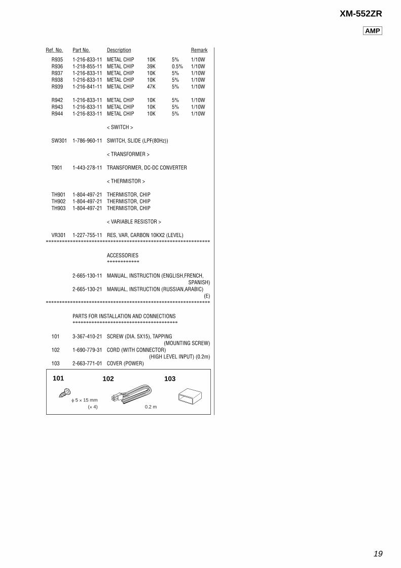
R935 1-216-833-11 METAL CHIP 10K 5% 1/10WR936 1-218-855-11 METAL CHIP 39K 0.5% 1/10WR937 1-216-833-11 METAL CHIP 10K 5% 1/10WR938 1-216-833-11 METAL CHIP 10K 5% 1/10WR939 1-216-841-11 METAL CHIP 47K 5% 1/10W
R942 1-216-833-11 METAL CHIP 10K 5% 1/10WR943 1-216-833-11 METAL CHIP 10K 5% 1/10WR944 1-216-833-11 METAL CHIP 10K 5% 1/10W
< SWITCH >
SW301 1-786-960-11 SWITCH, SLIDE (LPF(80Hz))
< TRANSFORMER >
T901 1-443-278-11 TRANSFORMER, DC-DC CONVERTER
< THERMISTOR >
TH901 1-804-497-21 THERMISTOR, CHIPTH902 1-804-497-21 THERMISTOR, CHIPTH903 1-804-497-21 THERMISTOR, CHIP
< VARIABLE RESISTOR >
VR301 1-227-755-11 RES, VAR, CARBON 10KX2 (LEVEL)*************************************************************
ACCESSORIES************
2-665-130-11 MANUAL, INSTRUCTION (ENGLISH,FRENCH,SPANISH)
2-665-130-21 MANUAL, INSTRUCTION (RUSSIAN,ARABIC)(E)
*************************************************************
PARTS FOR INSTALLATION AND CONNECTIONS***************************************
101 3-367-410-21 SCREW (DIA. 5X15), TAPPING(MOUNTING SCREW)
102 1-690-779-31 CORD (WITH CONNECTOR)(HIGH LEVEL INPUT) (0.2m)
103 2-663-771-01 COVER (POWER)
AMP
101 102 103
(× 4) 0.2 mφ 5 × 15 mm
20
XM-552ZR
REVISION HISTORY
Clicking the version allows you to jump to the revised page.Also, clicking the version at the upper on the revised page allows you to jump to the next revised page.
Ver. Date Description of Revision1.0 2006. 02 New1.1 2007. 08 Correction of PROTECTOR OPERATION CHECK. (ENG-07006)