Solutions to Physics: Principles with Applications , 5/E...
26
Solutions to Physics: Principles with Applications, 5/E, Giancoli Chapter 21 Page 21 – 1 CHAPTER 21 1. The magnitude of the average induced emf is å = – ®Φ B /®t = – A ®B/®t = – ?(0.046 m) 2 (0 – 1.5 T)/(0.20 s) = 0.050 V. 2. We assume the plane of the coil is perpendicular to the magnetic field. The magnitude of the average induced emf is å = – ®Φ B /®t = – A ®B/®t = – ?(0.080 m) 2 (0 – 1.10 T)/(0.15 s) = 0.15 V. 3. As the coil is pushed into the field, the magnetic flux increases into the page. To oppose this increase, the flux produced by the induced current must be out of the page, so the induced current is counterclockwise. 4. As the magnet is pushed into the coil, the magnetic flux increases to the right. To oppose this increase, flux produced by the induced current must be to the left, so the induced current in the resistor will be from right to left. 5. The average induced emf is å = – N ®Φ B /®t = – (2)[(+38 Wb) – (– 30 Wb)]/(0.42 s) = – 3.2 × 10 2 V. 6. We choose up as the positive direction. The average induced emf is å = – ®Φ B /®t = – A ®B/®t = – ?(0.036 m) 2 [(– 0.25 T) – (+ 0.63 T)]/(0.15 s) = 2.4 × 10 –2 V = 24 mV. 7. (a) As the resistance is increased, the current in the outer loop will decrease. Thus the flux through the inner loop, which is out of the page, will decrease. To oppose this decrease, the induced current in the inner loop will produce a flux out of the page, so the direction of the induced current will be counterclockwise. (b) If the small loop is placed to the left, the flux through the small loop will be into the page and will decrease. To oppose this decrease, the induced current in the inner loop will produce a flux into the page, so the direction of the induced current will be clockwise. B N S R B I B
Transcript of Solutions to Physics: Principles with Applications , 5/E...
Solutions to Physics: Principles with Applications, 5/E, Giancoli Chapter 21
Page 21 – 1
CHAPTER 21 1. The magnitude of the average induced emf is å = – ®ΦB/®t = – A ®B/®t = – ?(0.046 m)2(0 – 1.5 T)/(0.20 s) = 0.050 V. 2. We assume the plane of the coil is perpendicular to the magnetic field. The magnitude of the average
induced emf is å = – ®ΦB/®t = – A ®B/®t = – ?(0.080 m)2(0 – 1.10 T)/(0.15 s) = 0.15 V. 3. As the coil is pushed into the field, the magnetic flux increases into the page. To oppose this increase, the flux produced by the induced current must be out of the page, so the induced current is counterclockwise. 4. As the magnet is pushed into the coil, the magnetic flux increases to the right. To oppose this increase, flux produced by the induced current must be to the left, so the induced current in the resistor will be from right to left. 5. The average induced emf is å = – N ®ΦB/®t = – (2)[(+38 Wb) – (– 30 Wb)]/(0.42 s) = – 3.2 × 10² V. 6. We choose up as the positive direction. The average induced emf is å = – ®ΦB/®t = – A ®B/®t = – ?(0.036 m)2[(– 0.25 T) – (+ 0.63 T)]/(0.15 s) = 2.4 × 10⁻² V = 24 mV. 7. (a) As the resistance is increased, the current in the outer loop will decrease. Thus the flux through the inner loop, which is out of the page, will decrease. To oppose this decrease, the induced current in the inner loop will produce a flux out of the page, so the direction of the induced current will be counterclockwise. (b) If the small loop is placed to the left, the flux through the small loop will be into the page and will decrease. To oppose this decrease, the induced current in the inner loop will produce a flux into the page, so the direction of the induced current will be clockwise.
B
NS
R
B
I
B
Solutions to Physics: Principles with Applications, 5/E, Giancoli Chapter 21
Page 21 – 2
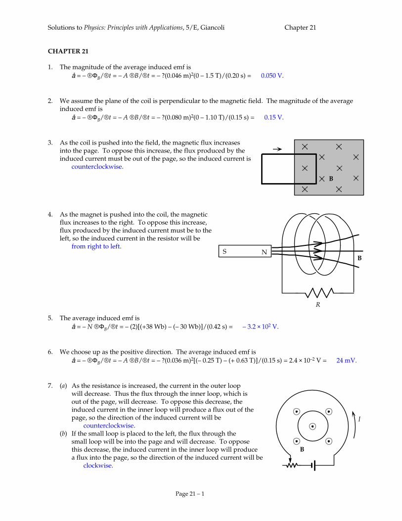
8. (a) The increasing current in the wire will cause an increasing field into the page through the loop. To oppose this increase, the induced current in the loop will produce a flux out of the page, so the direction of the induced current will be counterclockwise. (b) The decreasing current in the wire will cause a decreasing field into the page through the loop. To oppose this decrease, the induced current in the loop will produce a flux into the page, so the direction of the induced current will be clockwise. (c) Because the current is constant, there will be no change in flux, so the induced current will be zero. (d) The increasing current in the wire will cause an increasing field into the page through the loop. To oppose this increase, the induced current in the loop will produce a flux out of the page, so the direction of the induced current will be counterclockwise. 9. As the solenoid is pulled away from the loop, the magnetic flux to the right through the loop decreases. To oppose this decrease, the flux produced by the induced must be to the right, so the induced current is counterclockwise as viewed from the solenoid. 10. (a) The average induced emf is å = – ®ΦB/®t = – A ®B/®t = – ?(0.10 m)2[(– 0.45 T) – (+ 0.52 T)]/(0.180 s) = 0.17 V. (b) The positive result for the induced emf means the induced field is away from the observer, so the induced current is clockwise. 11. (a) Because the velocity is perpendicular to the magnetic field and the rod, we find the induced emf from å = BLv = (0.800 T)(0.120 m)(0.150 m/s) = 1.44 × 10⁻² V = 14.4 mV. (b) Because the upward flux is increasing, the induced flux will be into the page, so the induced current is clockwise. Thus the induced emf in the rod is down, which means that the electric field will be down. We find its magnitude from E = å/¬ = (1.44 × 10⁻² V)/(0.120 m) = 0.120 V/m down. 12. (a) The magnetic flux through the loop is into the paper and decreasing, because the area is decreasing. To oppose this decrease, the induced current in the loop will produce a flux into the paper, so the direction of the induced current will be clockwise. (b) We choose into the paper as the positive direction. The average induced emf is å = – ®ΦB/®t = – B ®A/®t = – ?B ®(D2)/®t
= – ?(0.75 T)[(0.030 m)2 – (0.100 m)2]/(0.50 s) = 4.3 × 10⁻² V = 43 mV. (c) We find the average induced current from I = å/R = (43 mV)/(2.5 Ω) = 17 mA.
B
I increasing
I decreasing
B
I increasingI constant
(a)
(d)
(b)
(c) B B
B
v
I I
¬vB
Solutions to Physics: Principles with Applications, 5/E, Giancoli Chapter 21
Page 21 – 3
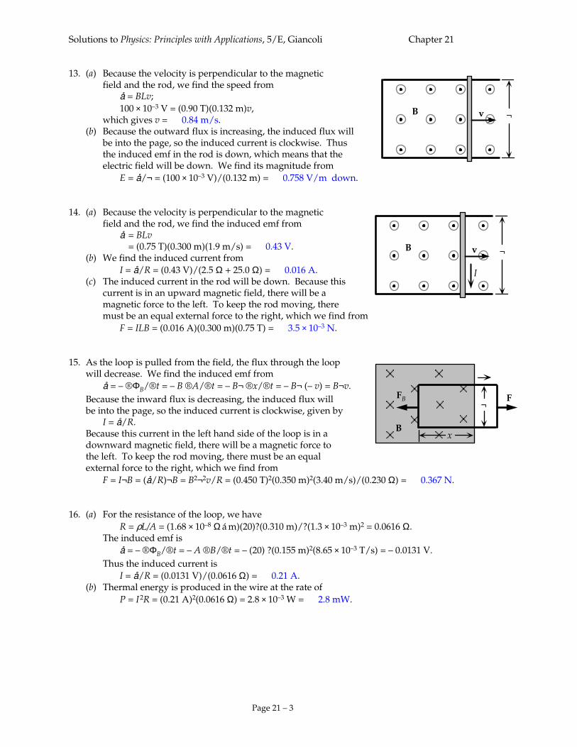
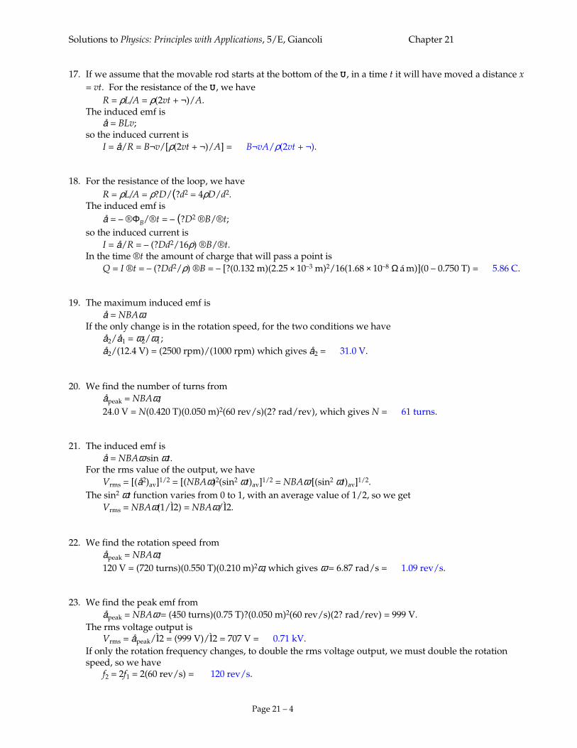
13. (a) Because the velocity is perpendicular to the magnetic field and the rod, we find the speed from å = BLv; 100 × 10–3 V = (0.90 T)(0.132 m)v, which gives v = 0.84 m/s. (b) Because the outward flux is increasing, the induced flux will be into the page, so the induced current is clockwise. Thus the induced emf in the rod is down, which means that the electric field will be down. We find its magnitude from E = å/¬ = (100 × 10–3 V)/(0.132 m) = 0.758 V/m down. 14. (a) Because the velocity is perpendicular to the magnetic field and the rod, we find the induced emf from å = BLv = (0.75 T)(0.300 m)(1.9 m/s) = 0.43 V. (b) We find the induced current from I = å/R = (0.43 V)/(2.5 Ω + 25.0 Ω) = 0.016 A. (c) The induced current in the rod will be down. Because this current is in an upward magnetic field, there will be a magnetic force to the left. To keep the rod moving, there must be an equal external force to the right, which we find from F = ILB = (0.016 A)(0.300 m)(0.75 T) = 3.5 × 10⁻³ N. 15. As the loop is pulled from the field, the flux through the loop will decrease. We find the induced emf from å = – ®ΦB/®t = – B ®A/®t = – B¬ ®x/®t = – B¬ (– v) = B¬v. Because the inward flux is decreasing, the induced flux will be into the page, so the induced current is clockwise, given by I = å/R. Because this current in the left hand side of the loop is in a downward magnetic field, there will be a magnetic force to the left. To keep the rod moving, there must be an equal external force to the right, which we find from F = I¬B = (å/R)¬B = B2¬2v/R = (0.450 T)2(0.350 m)2(3.40 m/s)/(0.230 Ω) = 0.367 N. 16. (a) For the resistance of the loop, we have R = ρL/A = (1.68 × 10⁻⁸ Ω á m)(20)?(0.310 m)/?(1.3 × 10–3 m)2 = 0.0616 Ω. The induced emf is å = – ®ΦB/®t = – A ®B/®t = – (20) ?(0.155 m)2(8.65 × 10⁻³ T/s) = – 0.0131 V. Thus the induced current is I = å/R = (0.0131 V)/(0.0616 Ω) = 0.21 A. (b) Thermal energy is produced in the wire at the rate of P = I
2R = (0.21 A)2(0.0616 Ω) = 2.8 × 10⁻³ W = 2.8 mW.
¬vB
¬vB
I
B
¬
x
FFB
Solutions to Physics: Principles with Applications, 5/E, Giancoli Chapter 21
Page 21 – 4
17. If we assume that the movable rod starts at the bottom of the U, in a time t it will have moved a distance x = vt. For the resistance of the U, we have
R = ρL/A = ρ(2vt + ¬)/A. The induced emf is å = BLv; so the induced current is I = å/R = B¬v/[ρ(2vt + ¬)/A] = B¬vA/ρ(2vt + ¬). 18. For the resistance of the loop, we have R = ρL/A = ρ?D/(?d2 = 4ρD/d2. The induced emf is å = – ®ΦB/®t = – (?D2 ®B/®t; so the induced current is I = å/R = – (?Dd2/16ρ) ®B/®t. In the time ®t the amount of charge that will pass a point is Q = I ®t = – (?Dd2/ρ) ®B = – [?(0.132 m)(2.25 × 10⁻³ m)2/16(1.68 × 10–8 Ω á m)](0 – 0.750 T) = 5.86 C. 19. The maximum induced emf is å = NBAω. If the only change is in the rotation speed, for the two conditions we have å2/å1 = ω2/ω1 ; å2/(12.4 V) = (2500 rpm)/(1000 rpm) which gives å2 = 31.0 V. 20. We find the number of turns from åpeak = NBAω; 24.0 V = N(0.420 T)(0.050 m)2(60 rev/s)(2? rad/rev), which gives N = 61 turns. 21. The induced emf is å = NBAω sin ωt. For the rms value of the output, we have Vrms = [(å2)av]1/2 = [(NBAω)2(sin2 ωt)av]1/2 = NBAω [(sin2 ωt)av]1/2. The sin2 ωt function varies from 0 to 1, with an average value of 1/2, so we get Vrms = NBAω(1/Ì2) = NBAω/Ì2. 22. We find the rotation speed from åpeak = NBAω; 120 V = (720 turns)(0.550 T)(0.210 m)2ω, which gives ω = 6.87 rad/s = 1.09 rev/s. 23. We find the peak emf from åpeak = NBAω = (450 turns)(0.75 T)?(0.050 m)2(60 rev/s)(2? rad/rev) = 999 V. The rms voltage output is Vrms = åpeak/Ì2 = (999 V)/Ì2 = 707 V = 0.71 kV. If only the rotation frequency changes, to double the rms voltage output, we must double the rotation
speed, so we have f2 = 2f1 = 2(60 rev/s) = 120 rev/s.
Solutions to Physics: Principles with Applications, 5/E, Giancoli Chapter 21
Page 21 – 5
24. We find the counter emf from å – åback = IR; 120 V – åback = (9.20 A)(3.75 Ω), which gives åback = 86 V. 25. Because the counter emf is proportional to the rotation speed, for the two conditions we have åback2/åback1 = ω2/ω1 ; åback2/(72 V) = (2500 rpm)/(1800 rpm), which gives åback2 = 100 V. 26. Because the counter emf is proportional to both the rotation speed and the magnetic field, for the two
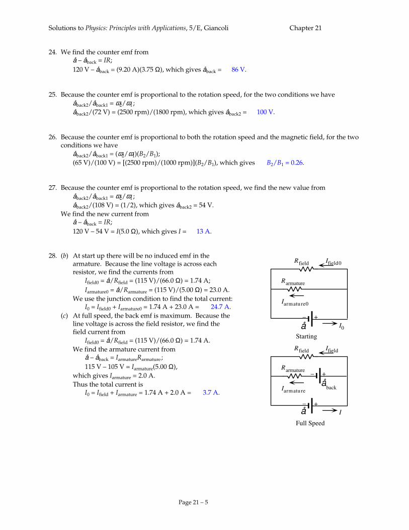
conditions we have åback2/åback1 = (ω2/ω1)(B2/B1); (65 V)/(100 V) = [(2500 rpm)/(1000 rpm)](B2/B1), which gives B2/B1 = 0.26. 27. Because the counter emf is proportional to the rotation speed, we find the new value from åback2/åback1 = ω2/ω1 ; åback2/(108 V) = (1/2), which gives åback2 = 54 V. We find the new current from å – åback = IR; 120 V – 54 V = I(5.0 Ω), which gives I = 13 A. 28. (b) At start up there will be no induced emf in the armature. Because the line voltage is across each resistor, we find the currents from Ifield0 = å/Rfield = (115 V)/(66.0 Ω) = 1.74 A; Iarmature0 = å/Rarmature = (115 V)/(5.00 Ω) = 23.0 A. We use the junction condition to find the total current: I0 = Ifield0 + Iarmature0 = 1.74 A + 23.0 A = 24.7 A. (c) At full speed, the back emf is maximum. Because the line voltage is across the field resistor, we find the field current from Ifield0 = å/Rfield = (115 V)/(66.0 Ω) = 1.74 A. We find the armature current from å – åback = IarmatureRarmature ; 115 V – 105 V = Iarmature(5.00 Ω), which gives Iarmature = 2.0 A. Thus the total current is I0 = Ifield + Iarmature = 1.74 A + 2.0 A = 3.7 A.
+–
Rarmature
åback
+–
I
Iarmatu re
Ifield
å
Rfield
+–
Rarmature
I0
Iarmatu re0
Ifield0
å
Rfield
Starting
Full Speed
Solutions to Physics: Principles with Applications, 5/E, Giancoli Chapter 21
Page 21 – 6
29. (a) We find the emf of the generator from the load conditions: V = å – IarmatureRarmature; 200 V = å – (50 A)(0.40 Ω), which gives å = 220 V. When there is no load on the generator, the current is zero, so the voltage will be the emf: 220 V. Note that no-load means little torque required to turn the generator. (b) Because the generator emf is proportional to the rotation speed, we find the new value from å2/å1 = ω2/ω1 ; å2/(220 V) = (800 rpm/1000 rpm), which gives å2 = 176 V. We find the new load voltage from V2 = å2 – IarmatureRarmature = 176 V – (50 A)(0.40 Ω) = 156 V. Note that the power output is reduced to 7.8 kW. 30. We find the number of turns in the secondary from VS/VP = NS/NP ; (10,000V)/(120 V) = NS/(5000 turns), which gives NS = 4.17 × 10⁵ turns. 31. Because NS < NP , this is a step-down transformer. We find the ratio of the voltages from VS/VP = NS/NP = (120 turns)/(420 turns) = 0.285. For the ratio of currents, we have IS/IP = NP/NS = (420 turns)/(120 turns) = 3.50. 32. With 100% efficiency, the power on each side of the transformer is the same: IPVP = ISVS , so we have IS/IP = VP/VS = (16 V)/(120) = 0.13. 33. We find the ratio of the number of turns from NS/NP = VS/VP = (12 × 103 V)/(220 V) = 55. If the transformer is connected backward, the role of the turns will be reversed: VS/VP = NS/NP ; VS/(220 V) = 1/55, which gives VS = 4.0 V. 34. (a) We assume 100% efficiency, so we have IPVP = ISVS ; (15 A)/(0.75 A) = (120 V)/VS , which gives VS = 6.0 V. (b) Because VS < VP , this is a step-down transformer. 35. (a) We assume 100% efficiency, so we find the input voltage from P= IPVP ; 100 W = (20 A)VP , which gives VP = 5.0 V. Because VS > VP , this is a step-up transformer. (b) For the voltage ratio we have VS/VP = (12 V)/(5.0 V) = 2.4.
Solutions to Physics: Principles with Applications, 5/E, Giancoli Chapter 21
Page 21 – 7
36. (a) Because VS < VP , this is a step-down transformer. (b) We assume 100% efficiency, so we find the current in the secondary from P= ISVS ; 40 W = IS(12 V), which gives IS = 3.3 A. (c) We find the current in the primary from P= IPVP ; 40 W = IP(120 V), which gives IS = 0.33 A. (d) We find the resistance of the bulb from VS = ISRS ; 120 V = (3.33 A)RS , which gives RS = 3.6 Ω. 37. We find the output voltage from VS/VP = NS/NP ; VS/(120 V) = (1240 turns)/(330 turns), which gives VS = 451 V. We find the input current from IS/IP = NP/NS ; (15.0 A)/IP = (330 turns)/(1240 turns), which gives IP = 56.4 A. 38. (a) We can find the current in the transmission lines from the output emf: Pout = IVout ; 30 × 106 W = I(45 × 103 V), which gives I = 667 A. We find the input emf from åin = Vout + IRlines = 45 × 103 V + (667 A)(4.0 Ω) = 48 × 103 = 48 kV. (b) The power loss in the lines is Ploss = I
2Rlines = (667 A)2(4.0 Ω) = 1.78 × 10⁶ W = 1.78 MW. The total power is Ptotal = Pout + Ploss = 30 MW + 1.78 MW = 31.8 MW, so the fraction lost is (1.78 MW)/(31.8 MW) = 0.056 (5.6%). 39. We can find the current in the transmission lines from the power transmitted to the user: PT = IV, or I = PT/V. The power loss in the lines is PL = I
2RL = (PT/V)2RL = (PT)2RL/V2.
Solutions to Physics: Principles with Applications, 5/E, Giancoli Chapter 21
Page 21 – 8
40. Without the transformers, we can find the delivered current, which is the current in the transmission lines, from the delivered power:
Pout = IVout ; 50 × 103 W = I(120V), which gives I = 417 A. The power loss in the lines is PL0 = I
2Rlines = (417 A)2(2)(0.100 Ω) = 3.48 × 10⁴ W = 34.8 kW. With the transformers, to deliver the same power at 120 V, the delivered current from the step-down
transformer is still 417 A. If the step-down transformer is 99% efficient, we have (0.99)IP2VP2 = IS2VS2 ; (0.99)IP2(1200 V) = (417 A)(120 V), which gives IP2 = 42.1 A. Because this is the current in the lines, the power loss in the lines is PL2 = IP2
2Rlines = (42.1 A)2(2)(0.100 Ω) = 3.55 × 10² W = 0.355 kW. For the 1% losses in the transformers, we approximate the power in each transformer: PLt = (0.01)(50 kW + 50.36 kW) = 1.00 kW. The total power loss using the transformers is PL = 0.355 kW + 1.00 kW = 1.4 kW. The power saved by using the transformers is Psaved = PL0 – PL = 34.8 kW – 1.4 kW = 33.4 kW. 41. We can find the delivered current, which is the current in the transmission lines, from the delivered
power: Pout = IVout ; 300 × 106 W = I(600 × 103 V), which gives I = 500 A. We can approximate the power at the input to the lines as 102% of the delivered power to account for the
loss. Thus the power loss in the lines is PL = (0.02)(1.02)Pout = I
2Rlines ; (0.02)(1.02)(300 × 106 W) = (500 A)2Rlines , which gives Rlines = 24.5 Ω. We find the radius of the 2 lines, each 200 km long, from R = ρL/A ; 24.5 Ω = (2.65 × 10⁻⁸ Ω á m)(2)(200 × 103 m)/?r2 , which gives r = 1.174 × 10⁻² m. Thus the diameter of the lines should be 2.35 cm. 42. We find the induced emf from å = – L ®I/®t = – (0.120 H)(10.0 A – 25.0 A)/(0.350 s) = 5.14 V. The emf is in the direction of the current, to oppose the decrease in the current. 43. We use the inductance of a solenoid: L = µ0AN2/¬ = (4? × 10–7 T á m/A)?(1.45 × 10–2 m)2(10,000 turns)2/(0.60 m) = 0.14 H. 44. Because the current in increasing, the emf is negative. We find the self-inductance from å = – L ®I/®t; – 8.50 V = – L[31.0 mA – (– 28.0 mA)]/(42.0 ms), which gives L = 6.05 H. 45. We find the number of turns from the inductance of a solenoid: L = µ0AN2/¬;
0.100 H = (4? × 10–7 T á m/A)?(2.6 × 10–2 m)2N2/(0.300 m), which gives N = 3.4 × 10³ turns.

Solutions to Physics: Principles with Applications, 5/E, Giancoli Chapter 21
Page 21 – 9
Solutions to Physics: Principles with Applications, 5/E, Giancoli Chapter 21
Page 21 – 10
46. We use the inductance of a solenoid: L = µ0AN2/¬ = (4? × 10–7 T á m/A)?(1.25 × 10–2 m)2(1000 turns)2/(0.282 m) = 2.2 × 10⁻³ H = 2.2 mH. If we form the ratio of inductances for the two conditions, we have L2/L1 = (µ/µ0)(N2/N1)2;
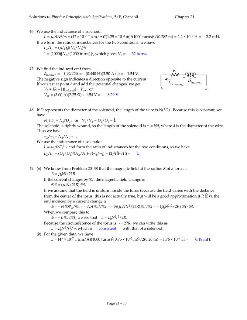
1 = (1000)[N2/(1000 turns)]2, which gives N2 = 32 turns. 47. We find the induced emf from åinduced = – L ®I/®t = – (0.440 H)(3.50 A/s) = – 1.54 V. The negative sign indicates a direction opposite to the current. If we start at point b and add the potential changes, we get Vb + IR + | åinduced | = Va , or Vab = (3.00 A)(2.25 Ω) + 1.54 V = 8.29 V. 48. If D represents the diameter of the solenoid, the length of the wire is N(?D). Because this is constant, we
have N1?D1 = N2?D2 , or N2/N1 = D1/D2 = !. The solenoid is tightly wound, so the length of the solenoid is ¬ = Nd, where d is the diameter of the wire.
Thus we have ¬2/¬1 = N2/N1 = !. We use the inductance of a solenoid: L = µ0AN2/¬, and form the ratio of inductances for the two conditions, so we have
L2/L1 = (D2/D1)2(N2/N1)2/(¬2/¬1) = (2)2(!)2/(!) = 2. 49. (a) We know from Problem 20–38 that the magnetic field at the radius R of a torus is B = µ0NI/2?R. If the current changes by ®I, the magnetic field change is ®B = (µ0N/2?R) ®I. If we assume that the field is uniform inside the torus (because the field varies with the distance from the center of the torus, this is not actually true, but will be a good approximation if R È r), the emf induced by a current change is å = – N ®ΦB/®t = – NA ®B/®t = – N(µ0N?r2/2?R) ®I/®t = – (µ0N
2r2/2R) ®I/®t. When we compare this to å = – L ®I/®t, we see that L = µ0N
2r2/2R. Because the circumference of the torus is ¬ = 2?R, we can write this as L = µ0N
2?r2/¬, which is consistent with that of a solenoid. (b) For the given data, we have L = (4? × 10–7 T á m/A)(1000 turns)2(0.75 × 10⁻² m)2/2(0.20 m) = 1.76 × 10⁻⁴ H = 0.18 mH.
R
å induced
+–Iincreasing
ab
Solutions to Physics: Principles with Applications, 5/E, Giancoli Chapter 21
Page 21 – 11
50. (a) For two inductors placed in series, the current through each inductor is the same. This current is also the current through the equivalent inductor, so the total emf is å = å1 + å2 = (– L1 ®I/®t) + (– L2 ®I/®t) = – (L1 + L2) ®I/®t = – Lseries ®I/®t, which gives Lseries = L1 + L2 . (b) For two inductors placed in parallel, the potential difference across each inductor, which is the emf, is the same: å = å1 = å2 = – L1 ®I1/®t = – L2 ®I2/®t = – Lparallel ®I/®t. The total current through the equivalent inductor is I = I1 + I2
, so we have ®I/®t = ®I1/®t + ®I2/®t; – å/Lparallel = – å/L1 – å/L2
, which gives 1/Lparallel = (1/L1) + (1/L2), or Lparallel = L1L2/(L1 + L2). (c) Each inductor will have an additional emf term: å1 = – L1 ®I1/®t ± M ®I2/®t, and å2 = – L2 ®I2/®t ± M ®I1/®t, where the sign of the mutual inductance term is determined by the orientation of one winding with respect to the other. For the series arrangement, if we assume that the windings are such that the fields of each inductor are in the same direction, the induced emf from the mutual inductance will be in the same direction (have the same sign) as the self-induced emfs. Because I1 = I2 = I, we have å = å1 + å2 ; – Lseries ®I/®t = (– L1 ®I/®t – M ®I/®t) + (– L2 ®I/®t – M ®I/®t) = – (L1 + L2 + 2M) ®I/®t , which gives Lseries = L1 + L2 + 2M. For the parallel arrangement, if we assume that the windings are such that the internal fields of each inductor are in the same direction, the induced emf from the mutual inductance will be in the opposite direction (have the opposite sign) from the self-induced emfs: å = å1 = – L1 ®I1/®t + M ®I2/®t = å2 = – L2 ®I2/®t + M ®I1/®t. When these equations are combined, we get ®I1/®t = – (L2 + M)å/(L1L2 – M2), and ®I2/®t = – (L1 + M)å/(L1L2 – M2). Because I = I1 + I2
, we have ®I/®t = ®I1/®t + ®I2/®t;
– å/Lparallel = – (L2 + M)å/(L1L2 – M2) – (L1 + M)å/(L1L2 – M2), which gives Lparallel = (L1L2 – M2)/(L1 + L2 + 2M). 51. The magnetic field of the solenoid, which passes through the coil is B = µ0N1I1/¬. When the current in the solenoid changes, the induced emf in the coil is å = – N2A ®B/®t = – N2(µ0N1A /¬) ®I1/®t = – M ®I1/®t. Thus we get M = µ0N1N2A /¬. 52. (a) We find the magnetic field from the first coil using the expression for a solenoid: B = µN1I1/¬ = (3000)(4? × 10–7 T á m/A)(1500 turns)I1/(0.30 m) = (18.85 T/A)I1 . The induced emf in the second coil is å = – N2A ®B/®t
= – (800 turns)?(0.020 m)2(18.85 T/A) ®I1/®t
= – (18.95 T á m2/A)(0 – 3.0 A)/(0.0080 s) = 7.1 × 10³ V. (b) We find the mutual inductance from å = – M ®I1/®t;

Solutions to Physics: Principles with Applications, 5/E, Giancoli Chapter 21
Page 21 – 12
7.1 × 10³ V = – M(0 – 3.0 A)/0.0080 s), which gives M = 19.0 H.
Solutions to Physics: Principles with Applications, 5/E, Giancoli Chapter 21
Page 21 – 13
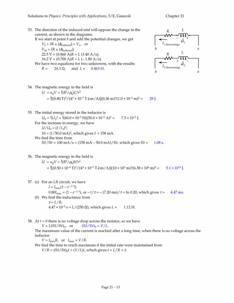
53. The direction of the induced emf will oppose the change in the current, as shown in the diagrams. If we start at point b and add the potential changes, we get Vb + IR ± | åinduced | = Va , or Vab = IR ± | åinduced |; 22.5 V = (0.860 A)R + L (3.40 A/s); 16.2 V = (0.700 A)R + L (– 1.80 A/s). We have two equations for two unknowns, with the results: R = 24.3 Ω, and L = 0.463 H. 54. The magnetic energy in the field is U = uBV = !(B2/µ0)L?r2
= ?(1.0 × 10⁻² m)2 = 29 J. 55. The initial energy stored in the inductor is U0 = !LI 0
2 = !(60.0 × 10⁻³ H)(50.0 × 10⁻³ A)2 = 7.5 × 10⁻⁵ J. For the increase in energy, we have U/U0 = (I /I 0)2; 10 = (I /50.0 mA)2, which gives I = 158 mA. We find the time from ®I /®t = 100 mA/s = (158 mA – 50.0 mA)/®t, which gives ®t = 1.08 s. 56. The magnetic energy in the field is U = uBV = !(B2/µ0)h?r2
= ?(6.38 × 10⁶ m)2 = 5.1 × 10¹⁵ J. 57. (a) For an LR circuit, we have I = Imax(1 – e– t/τ); 0.80Imax = (1 – e– t/τ), or – t/τ = – (7.20 ms)/τ = ln 0.20, which gives τ = 4.47 ms. (b) We find the inductance from τ = L/R; 4.47 × 10⁻³ s = L/(250 Ω), which gives L = 1.12 H. 58. At t = 0 there is no voltage drop across the resistor, so we have V = L(®I/®t)0 , or (®I/®t)0 = V/L. The maximum value of the current is reached after a long time, when there is no voltage across the
inductor: V = ImaxR, or Imax = V/R. We find the time to reach maximum if the initial rate were maintained from V/R = (®I/®t)0t = (V/L)t, which gives t = L/R = τ.
R
å1
+–I1 (increasing)
ab
R
å2
–+I2 (decreasing)
ab
L
L
Solutions to Physics: Principles with Applications, 5/E, Giancoli Chapter 21
Page 21 – 14
59. For an LR circuit, we have I = Imax(1 – e– t/τ), which we can write as e– t/τ = 1 – (I/Imax), or t/τ = – ln[1 – (I/Imax)] = – ln[(Imax – I)/Imax]. (a) ta/τ = – ln(0.10), which gives ta/τ = 2.3. (b) tb/τ = – ln(0.010), which gives tb/τ = 4.6. (c) tc/τ = – ln(0.001), which gives tc/τ = 6.9. 60. (a) We use the inductance of a solenoid: L = µ0AN2/¬. Because they are tightly wound, the number of turns is determined by the diameter of the wire: N = ¬/d. If we form the ratio of inductances for the two conditions, we have L1/L2 = (N1/N2)2 = (d2/d1)2 = 22 = 4. (b) The length of wire used for the turns is ¬wire = N(?D), where D is the diameter of the solenoid.
Thus for the ratio of resistances, we have R1/R2 = (¬wire1/¬wire2)(d2/d1)2 = (N1/N2)(d2/d1)2 = (d2/d1)3. For the ratio of the time constants, we get τ1/τ2 = (L1/L2)(R2/R1) = (L1/L2)(d1/d2)3 = (4)(!)3 = !. 61. We find the frequency from XL = ωL = 2?fL;
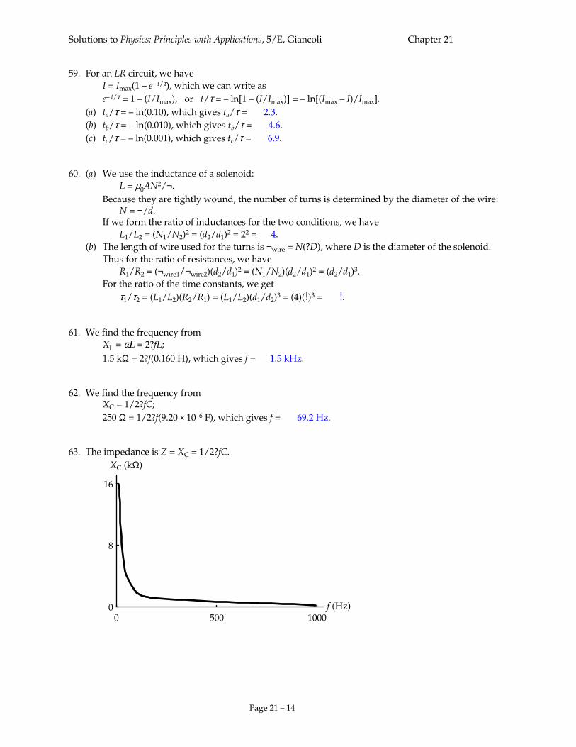
1.5 kΩ = 2?f(0.160 H), which gives f = 1.5 kHz. 62. We find the frequency from XC = 1/2?fC; 250 Ω = 1/2?f(9.20 × 10–6 F), which gives f = 69.2 Hz. 63. The impedance is Z = XC = 1/2?fC.
16
00 1000
f (Hz)
XC (kΩ)
8
500
Solutions to Physics: Principles with Applications, 5/E, Giancoli Chapter 21
Page 21 – 15
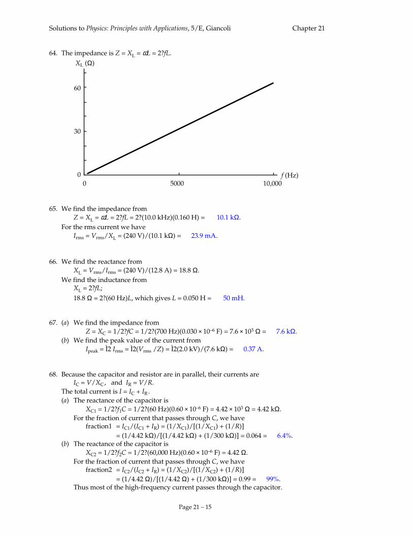
64. The impedance is Z = XL = ωL = 2?fL.
f (Hz)10,00050000
0
30
60
XL (Ω)
65. We find the impedance from Z = XL = ωL = 2?fL = 2?(10.0 kHz)(0.160 H) = 10.1 kΩ. For the rms current we have Irms = Vrms/XL = (240 V)/(10.1 kΩ) = 23.9 mA. 66. We find the reactance from XL = Vrms/Irms = (240 V)/(12.8 A) = 18.8 Ω. We find the inductance from XL = 2?fL; 18.8 Ω = 2?(60 Hz)L, which gives L = 0.050 H = 50 mH. 67. (a) We find the impedance from Z = XC = 1/2?fC = 1/2?(700 Hz)(0.030 × 10⁻⁶ F) = 7.6 × 10³ Ω = 7.6 kΩ. (b) We find the peak value of the current from Ipeak = Ì2 Irms = Ì2(Vrms /Z) = Ì2(2.0 kV)/(7.6 kΩ) = 0.37 A. 68. Because the capacitor and resistor are in parallel, their currents are IC = V/XC , and IR = V/R. The total current is I = IC + IR . (a) The reactance of the capacitor is XC1 = 1/2?f1C = 1/2?(60 Hz)(0.60 × 10⁻⁶ F) = 4.42 × 10³ Ω = 4.42 kΩ. For the fraction of current that passes through C, we have fraction1 = IC1/(IC1 + IR) = (1/XC1)/[(1/XC1) + (1/R)] = (1/4.42 kΩ)/[(1/4.42 kΩ) + (1/300 kΩ)] = 0.064 = 6.4%. (b) The reactance of the capacitor is XC2 = 1/2?f2C = 1/2?(60,000 Hz)(0.60 × 10⁻⁶ F) = 4.42 Ω. For the fraction of current that passes through C, we have fraction2 = IC2/(IC2 + IR) = (1/XC2)/[(1/XC2) + (1/R)] = (1/4.42 Ω)/[(1/4.42 Ω) + (1/300 kΩ)] = 0.99 = 99%. Thus most of the high-frequency current passes through the capacitor.

Solutions to Physics: Principles with Applications, 5/E, Giancoli Chapter 21
Page 21 – 16
Solutions to Physics: Principles with Applications, 5/E, Giancoli Chapter 21
Page 21 – 17
69. Because the capacitor and resistor are in series, the impedance of the circuit is Z = (R2 + XC
2)1/2, so the current is I = V/Z, and the voltage across the resistor is VR = IR. (a) The reactance of the capacitor is XC1 = 1/2?f1C = 1/2?(60 Hz)(2.0 × 10⁻⁶ F) = 1.33 × 10³ Ω = 1.33 kΩ. The impedance of the circuit is Z1 = (R2 + XC1
2)1/2 = [(0.500 kΩ)2 + (1.33 kΩ)2]1/2 = 1.42 kΩ. The current is I1 = V/Z1 = (50 mV)/(1.42 kΩ) = 35.2 µA. The voltage across the resistor is VR1 = I1R = (35.2 µA)(0.500 kΩ) = 18 mV. (b) The reactance of the capacitor is XC1 = 1/2?f1C = 1/2?(60,000 Hz)(2.0 × 10⁻⁶ F) = 1.33 Ω. The impedance of the circuit is Z1 = (R2 + XC1
2)1/2 = [(0.500 kΩ)2 + (0.00133 kΩ)2]1/2 = 0.500 kΩ. The current is I1 = V/Z1 = (50 mV)/(0.500 kΩ) = 100 µA. The voltage across the resistor is VR1 = I1R = (100 µA)(0.500 kΩ) = 50 mV. Thus the high-frequency signal passes to the resistor. 70. (a) The reactance of the inductor is XL1 = 2?f1L = 2?(60 Hz)(0.50 H) = 188 Ω. The impedance of the circuit is Z1 = (R2 + XL1
2)1/2 = [(30 kΩ)2 + (0.188 kΩ)2]1/2 = 30 kΩ. (b) The reactance of the inductor is XL2 = 2?f2L = 2?(30 kHz)(0.50 H) = 94.2 kΩ. The impedance of the circuit is Z2 = (R2 + XL2
2)1/2 = [(30 kΩ)2 + (94.2 kΩ)2]1/2 = 99 kΩ. 71. (a) The reactance of the capacitor is XC1 = 1/2?f1C = 1/2?(100 Hz)(4.0 × 10⁻⁶ F) = 398 Ω = 0.398 kΩ. The impedance of the circuit is Z1 = (R2 + XC1
2)1/2 = [(1.5 kΩ)2 + (0.398 kΩ)2]1/2 = 1.6 kΩ. (b) The reactance of the capacitor is XC2 = 1/2?f2C = 1/2?(10,000 Hz)(4.0 × 10⁻⁶ F) = 3.98 Ω = 0.00398 kΩ. The impedance of the circuit is Z2 = (R2 + XC2
2)1/2 = [(1.5 kΩ)2 + (0.00398 kΩ)2]1/2 = 1.5 kΩ. 72. We find the impedance from Z = Vrms/Irms = (120 V)/(70 mA) = 1.7 kΩ.
Solutions to Physics: Principles with Applications, 5/E, Giancoli Chapter 21
Page 21 – 18
73. At 60 Hz, the reactance of the inductor is XL1 = 2?f1L = 2?(60 Hz)(0.420 H) = 158 Ω. The impedance of the circuit is Z1 = (R2 + XL1
2)1/2 = [(2.5 kΩ)2 + (0.158 kΩ)2]1/2 = 2.51 kΩ. Thus the impedance at the new frequency is Z2 = 2Z1 = 2(2.51 kΩ) = 5.02 kΩ. We find the new reactance from Z2 = (R2 + XL2
2)1/2; 5.02 kΩ = [(2.5 kΩ)2 + XL2
2]1/2 , which gives XL2 = 4.34 kΩ. We find the new frequency from XL2 = 2?f2L; 4.34 kΩ = 2?f2(0.420 H), which gives f2 = 1.6 kHz. 74. (a) The reactance of the capacitor is XC = 1/2?fC = 1/2?(60 Hz)(0.80 × 10⁻⁶ F) = 3.32 × 10³ Ω = 3.32 kΩ. The impedance of the circuit is Z = (R2 + XC
2)1/2 = [(28.8 kΩ)2 + (3.32 kΩ)2]1/2 = 29.0 kΩ. The rms current is Irms = Vrms/Z = (120 V)/(29.0 kΩ) = 4.14 mA. (b) We find the phase angle from cos φ = R/Z = (28.8 kΩ)/(29.0 kΩ) = 0.993. In an RC circuit, the current leads the voltage, so φ = – 6.6¡. (c) The power dissipated is P = Irms
2R = (4.14 × 10⁻³ A)2(28.8 × 10³ Ω) = 0.49 W. (d) The rms readings across the elements are VR = IrmsR = (4.14 mA)(28.8 kΩ) = 119 V; VC = IrmsXC = (4.14 mA)(3.32 kΩ) = 14 V. Note that, because the maximum voltages occur at different times, the two readings do not add to the applied voltage of 120 V. 75. (a) The reactance of the inductor is XL = 2?fL = 2?(60 Hz)(0.900 H) = 339 Ω = 0.339 kΩ. The impedance of the circuit is Z = (R2 + XL
2)1/2 = [(1.80 kΩ)2 + (0.339 kΩ)2]1/2 = 1.83 kΩ. The rms current is Irms = Vrms/Z = (120 V)/(1.83 kΩ) = 65.5 mA. (b) We find the phase angle from cos φ = R/Z = (1.80 kΩ)/(1.83 kΩ) = 0.984. In an RL circuit, the current lags the voltage, so φ = + 10.4¡. (c) The power dissipated is P = Irms
2R = (65.5 × 10⁻³ A)2(1.80 × 10³ Ω) = 7.73 W. (d) The rms readings across the elements are VR = IrmsR = (65.5 mA)(1.80 kΩ) = 118 V; VL = IrmsXL = (65.5 mA)(0.339 kΩ) = 22 V. Note that, because the maximum voltages occur at different times, the two readings do not add to the applied voltage of 120 V.
Solutions to Physics: Principles with Applications, 5/E, Giancoli Chapter 21
Page 21 – 19
76. The reactance of the capacitor is XC = 1/2?fC = 1/2?(10.0 × 103 Hz)(5000 × 10–12 F) = 3.18 × 10³ Ω = 3.18 kΩ. The reactance of the inductor is XL = 2?fL = 2?(10.0 kHz)(0.0220 H) = 1.38 kΩ. The impedance of the circuit is Z = [R2 + (XL – XC)2]1/2 = [(8.70 kΩ)2 + (1.38 kΩ – 3.18 kΩ)2]1/2 = 8.88 kΩ. We find the phase angle from tan φ = (XL – XL)/R = (1.38 kΩ – 3.18 kΩ)/(8.70 kΩ) = – 0.207, so φ = – 11.7¡. The rms current is Irms = Vrms/Z = (300 V)/(8.70 kΩ) = 34.5 mA. 77. We find the reactance from Z = [R2 + XL
2]1/2 ; 35 Ω = [R2 + (30 Ω)2]1/2, which gives R = 18 Ω. 78. From the expression for V, we see that V0 = 4.8 V, and 2?f = 754 s–1. For the reactances, we have XC = 1/2?fC = 1/(754 s–1)(3.0 × 10⁻⁶ F) = 442 Ω. XL = 2?fL = (754 s–1)(0.0030 H) = 2.26 Ω. The impedance of the circuit is Z = [R2 + (XL – XC)2]1/2 = [(1.40 kΩ)2 + (0.00226 kΩ – 0.442 kΩ)2]1/2 = 1.47 kΩ. The power dissipated is P = Irms
2R = (Vrms/Z)2R = (V0/ZÌ2)2R = !(V0/Z)2R
= !(4.8 V/1.47 × 103 Ω)2(1.40 × 10³ Ω) = 7.5 × 10⁻³ W = 7.5 mW. 79. We find the rms current from P = Irms
2R; 9.50 W = Irms
2(250 Ω), which gives Irms = 0.195 A. We find the impedance from Z = Vrms/Irms = (50.0 V)/(0.195 A) = 256 Ω. From this we can find the reactance of the coil: Z2 = R2 + XL
2; (256 Ω)2 = (250 Ω)2 + XL
2, which gives XL = 57.4 Ω. We find the frequency that will produce this reactance from XL = 2?fL ; 57.4 Ω = 2?f(0.040 H), which gives f = 228 Hz. 80. The voltage across the resistor is in phase with the current: VR = IR = (I0 cos ωt) = I0R cos ωt. The voltage across the inductor leads the current by 90¡ or ?/2: VL = I0 cos (ωt + ?/2)XL = I0ωL cos (ωt + ?/2). The voltage across the capacitor lags the current by 90¡ or ?/2: VC = I0 cos (ωt – ?/2)XC = (I0/ωC) cos (ωt – ?/2). 81. The resonant frequency is f0 = (1/2?)(1/LC)1/2 = [1/(50 × 10–6 H)(3500 × 10–12 F)]1/2 = 3.8 × 10⁵ Hz.

Solutions to Physics: Principles with Applications, 5/E, Giancoli Chapter 21
Page 21 – 20
Solutions to Physics: Principles with Applications, 5/E, Giancoli Chapter 21
Page 21 – 21
82. (a) The resonant frequency is given by f0
2 = (1/2?)2(1/LC). When we form the ratio for the two stations, we get (f02/f01)2 = C1/C2 ; (1600 kHz/580 kHz)2 = (2800 pF)/C2 , which gives C2 = 368 pF. (b) We find the inductance from the first frequency: f01 = (1/2?)(1/LC1)1/2; 580 × 103 Hz = (1/2?)[1/L(2800 × 10–12 F)]1/2, which gives L = 2.68 × 10⁻⁵ H = 26.8 µH. 83. (a) We find the capacitance from the frequency: f0 = (1/2?)(1/LC)1/2; 3600 Hz = (1/2?)[1/(4.8 × 10–3 H)C]1/2 , which gives C = 4.07 × 10⁻⁷ F = 0.41 µF. (b) At resonance the impedance is the resistance, so the current is I0 = V0/R = (50 V)/(4.4 Ω) = 11A. 84. (a) The frequency of oscillation is the resonance frequency. We find the inductance from f0 = (1/2?)(1/LC)1/2; 20 × 103 Hz = (1/2?)[1/L(3000 × 10–12 F)]1/2, which gives L = 2.11 × 10⁻² H = 21 mH. (b) The energy initially stored in the capacitor will oscillate between the capacitor and the inductor. We find the maximum current, when all of the energy is stored in the inductor, by equating the maximum energies: !CV0
2 = !LImax2;
(3000 × 10–12 F)(120 V)2 = (2.11 × 10⁻² H)Imax2, which gives Imax = 4.5 × 10⁻² A = 45 mA.
(b) The maximum energy stored in the inductor is ULmax = !LImax
2 = !(2.11 × 10⁻² H)(4.5 × 10⁻² A)2 = 2.2 × 10⁻⁵ J. 85. We find the equivalent resistance of the two speakers in parallel from 1/Req = (1/R1) + (1/R2) = (1/8 Ω) + (1/8 Ω), which gives Req = 4 Ω. Thus the speakers should be connected to the 4 Ω terminals. 86. Because the loudspeaker is connected to the secondary side of the transformer, we have ZP/ZS = (NP/NS)2; (30 × 103 Ω)/(8.0 Ω) = (NP/NS)2, which gives NP/NS = 61. 87. (a) Because the increasing current in the first loop produces an increasing magnetic field in the second loop, yes, there will be an induced current in the second loop. (b) Because the current in the first loop increases immediately, the induced current will increase immediately. (c) The induced current will stop when the current in the first loop reaches the steady state. (d) To oppose the increase in the magnetic field away from you from the first loop, the induced current will produce a magnetic field toward you. Thus the induced current will be counterclockwise. (e) While there is an induced current, the loops will have parallel opposite currents, so, yes, there will be a force. (f) Because we have opposite currents, the force is repulsive, so the force on each loop is away from the other loop.
Solutions to Physics: Principles with Applications, 5/E, Giancoli Chapter 21
Page 21 – 22
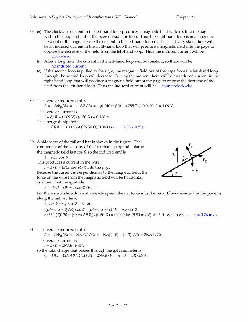
88. (a) The clockwise current in the left-hand loop produces a magnetic field which is into the page within the loop and out of the page outside the loop. Thus the right-hand loop is in a magnetic field out of the page. Before the current in the left-hand loop reaches its steady state, there will be an induced current in the right-hand loop that will produce a magnetic field into the page to oppose the increase of the field from the left-hand loop. Thus the induced current will be clockwise. (b) After a long time, the current in the left-hand loop will be constant, so there will be no induced current. (c) If the second loop is pulled to the right, the magnetic field out of the page from the left-hand loop through the second loop will decrease. During the motion, there will be an induced current in the right-hand loop that will produce a magnetic field out of the page to oppose the decrease of the field from the left-hand loop. Thus the induced current will be counterclockwise. 89. The average induced emf is å = – ®ΦB/®t = – A ®B/®t = – (0.240 m)2(0 – 0.755 T)/(0.0400 s) = 1.09 V. The average current is I = å/R = (1.09 V)/(6.50 Ω) = 0.168 A. The energy dissipated is E = I2R ®t = (0.168 A)2(6.50 Ω)(0.0400 s) = 7.33 × 10⁻³ J. 90. A side view of the rail and bar is shown in the figure. The component of the velocity of the bar that is perpendicular to the magnetic field is v cos θ, so the induced emf is å = BLv cos θ. This produces a current in the wire I = å/R = (BLv cos θ)/R into the page. Because the current is perpendicular to the magnetic field, the force on the wire from the magnetic field will be horizontal, as shown, with magnitude FB = I¬B = (B2¬2v cos θ)/R. For the wire to slide down at a steady speed, the net force must be zero. If we consider the components
along the rail, we have FB cos θ – mg sin θ = 0, or
[(B2¬2v cos θ)/R] cos θ = (B2¬2v cos2 θ)/R = mg sin θ; (0.55 T)2(0.30 m)2v(cos2 5.0¡)/(0.60 Ω) = (0.040 kg)(9.80 m/s2) sin 5.0¡, which gives v = 0.76 m/s. 91. The average induced emf is å = – ®ΦB/®t = – NA ®B/®t = – NA[(– B) – (+ B)]/®t = 2NAB/®t. The average current is I = å/R = 2NAB/R ®t, so the total charge that passes through the galvanometer is Q = I ®t = (2NAB/R ®t) ®t = 2NAB/R, or B = QR/2NA.
B
FB
FN
mgs
θ
v
Solutions to Physics: Principles with Applications, 5/E, Giancoli Chapter 21
Page 21 – 23
92. (a) The velocity of the bar is perpendicular to the magnetic field, so the induced emf is å = BLv. This produces a current in the wire I = å/R = BLv/R downward. Because the current is perpendicular to the magnetic field, the force on the wire from the magnetic field will be horizontal to the left with magnitude FB = I¬B = B2¬2v/R. An external force of this magnitude must be exerted to the right to maintain the motion. The power expended by this force is P = Fv = (B2¬2v/R)v = B2¬2v2/R. (b) The power dissipated in the resistance is P = I
2R = (BLv/R)2R = B2¬2v2/R, which is the power expended by the external force. We expect this, since there is no increase in kinetic energy. 93. (a) From the efficiency of the transformer, we have PS = 0.80PP. For the power input to the transformer, we have PP = IPVP ; (58 W)/0.80 = IP(110 V), which gives IP = 0.66 A. (b) We find the secondary voltage from PP = VS
2/RS ; 58 W = VS
2/(2.4 Ω), which gives VS = 11.8 V. We find the ratio of the number of turns from NP/NS = VP/VS = (110 V)/(11.8 V) = 9.3. 94. (a) The voltage drop across the lines is ®V = 2IR = 2(700 A)(0.80 Ω) = 1.12 × 10³ V = 1.12 kV. Thus the voltage at the other end is Vout = Vin – ®V = 42 kV – 1.12 kV = 41 kV. (b) The power input is Pin = IVin = (0.700 kA)(42 kV) = 29.4 MW. (c) The power loss in the lines is Ploss = 2I
2R = 2(0.700 kA)2(0.80 Ω) = 0.78 MW. (d) The power output is Pout = IVout = (0.700 kA)(40.9 kV) = 28.6 MW. 95. We find the peak emf from åpeak = NBAω = (125 turns)(0.200 T)(0.066 m)2(120 rev/s)(2? rad/rev) = 82 V.
Solutions to Physics: Principles with Applications, 5/E, Giancoli Chapter 21
Page 21 – 24
96. (a) Because we have direct coupling, the torque provided by the motor balances the torque of the friction force: NIAB = Fr; (300 turns)I(0.10 m)(0.15 m)(0.60 T) = (250 N)(0.25 m), which gives I = 23 A. (b) To maintain the speed, we have a force equal to the friction force, so the power required is Fv = (250 N)(30 km/h)/(3.6 ks/h) = 2.08 × 10³ W. This must be provided by the net power from the motor, which is Pnet = IVin – I
2R = I(Vin – IR) = Iåback = Fv; (23 A)åback = 2.08 × 10³ W, which gives åback = 90 V. (c) The power dissipation in the coils is Ploss = Pin – Pnet = (23 A)(10)(12 V) – 2.08 × 10³ W = 6.9 × 10² W. (d) The useful power percentage is (Pnet/Pin)(100) = (Iåback/IVin)(100) = (90 V/120 V)(100) = 75%. 97. We find the impedance from Z = XL = Vrms/Irms = (220 V)/(5.8 A) = 37.9 Ω. We find the inductance from XL = 2?fL; 37.9 Ω = 2?(60 Hz)L, which gives L = 0.10 H. 98. For the current and voltage to be in phase, the net reactance of the capacitor and inductor must be zero,
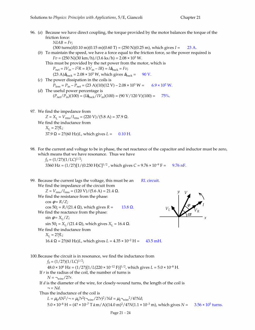
which means that we have resonance. Thus we have f0 = (1/2?)(1/LC)1/2; 3360 Hz = (1/2?)[1/(0.230 H)C]1/2 , which gives C = 9.76 × 10⁻⁹ F = 9.76 nF. 99. Because the current lags the voltage, this must be an RL circuit. We find the impedance of the circuit from Z = Vrms/Irms = (120 V)/(5.6 A) = 21.4 Ω. We find the resistance from the phase: cos φ = R/Z; cos 50¡ = R/(21.4 Ω), which gives R = 13.8 Ω. We find the reactance from the phase: sin φ = XL/Z; sin 50¡ = XL/(21.4 Ω), which gives XL = 16.4 Ω. We find the inductance from XL = 2?fL;
16.4 Ω = 2?(60 Hz)L, which gives L = 4.35 × 10⁻² H = 43.5 mH. 100. Because the circuit is in resonance, we find the inductance from f0 = (1/2?)(1/LC)1/2; 48.0 × 10⁶ Hz = (1/2?)[1/L(220 × 10–12 F)]1/2, which gives L = 5.0 × 10⁻⁸ H. If r is the radius of the coil, the number of turns is N = ¬wire/2?r. If d is the diameter of the wire, for closely-wound turns, the length of the coil is ¬ = Nd. Thus the inductance of the coil is L = µ0AN2/¬ = µ0?r2(¬wire/2?r)2/Nd = µ0¬wire
2/4?Nd;
5.0 × 10⁻⁸ H = (4? × 10–7 T á m/A)(14.0 m)2/4?N(1.1 × 10–3 m), which gives N = 3.56 × 10⁵ turns.
x
y
ωt
V
IφVL VR

Solutions to Physics: Principles with Applications, 5/E, Giancoli Chapter 21
Page 21 – 25
Solutions to Physics: Principles with Applications, 5/E, Giancoli Chapter 21
Page 21 – 26
101. We find the resistance of the coil from the dc current: R = Vdc/Idc = (36 V)/(2.5 A) = 14 Ω. We find the impedance from the ac current: Z = Vrms/Irms = (120 V)/(3.8 A) = 31.6 Ω. We find the reactance from Z = [R2 + XL
2]1/2 ; 31.6 Ω = [(14.4 Ω)2 + XL
2]1/2, which gives XL = 28.1 Ω. We find the inductance from XL = 2?fL; 28.1 Ω = 2?(60 Hz)L, which gives L = 0.075 H = 75 mH. 102. (a) At resonance we have 2?f0 = (1/LC)1/2. The Q factor is Q = VC/VR = IrmsXC/IrmsR = 1/2?f0CR = (LC)1/2/CR = (1/R)(L/C)1/2. (b) We find the inductance from the resonance frequency: 2?f0 = (1/LC)1/2; 2?(1.0 × 10⁶ Hz) = [1/L(0.010 × 10–6 F)], which gives L = 2.5 × 10⁻⁶ H = 2.5 µH. We find the resistance required from Q = (1/R)(L/C)1/2; 1000 = (1/R)[(2.5 × 10–6 H)/(0.010 × 10–6 F)], which gives R = 1.6 × 10⁻² Ω. 103. We find the impedance from the power factor: cos φ = R/Z ; 0.17 = (200 Ω)/Z , which gives Z = 1.18 × 10³ Ω. We get an expression for the reactances from Z2 = R2 + (XL – XC)2;
(1.18 × 10³ Ω)2 = (200 Ω)2 + (XL – XC)2, which gives XL – XC = ± 1.16 × 10³ Ω. When we express this in terms of the inductance and capacitance, we get 2?fL – (1/2?fC) = ± 1.16 × 10³ Ω; 2?f(0.020 H) – [1/2?f(50 × 10–9 F)] = ± 1.16 × 10³ Ω, which reduces to two quadratic equations: 0.126f
2 ± (1.16 × 10³ Hz)f – 3.183 × 10⁶ Hz2, which have positive solutions of f = 2.2 × 10³ Hz, 1.1 × 10⁴ Hz.