Solutions to Chapter 3 Exercise Problemssv.20file.org/up1/645_0.pdf · Solutions to Chapter 3...
137
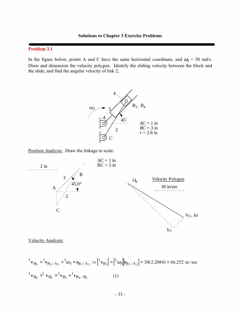
- 33 - Solutions to Chapter 3 Exercise Problems Problem 3.1 In the figure below, points A and C have the same horizontal coordinate, and ω 3 = 30 rad/s. Draw and dimension the velocity polygon. Identify the sliding velocity between the block and the slide, and find the angular velocity of link 2. 4 2 B 3 , B 4 A ω 3 3 AC = 1 in BC = 3 in r = 2.8 in C 45˚ Position Analysis: Draw the linkage to scale. AC = 1 in BC = 3 in 30 in/sec Velocity Polygon O v b 3 b4 b 2 , A B C 2 in 3 2 45.0° Velocity Analysis: 1 v B 3 = 1 v B 3 /A 3 = 1 ω 3 × r B 3 /A 3 ⇒ 1 v B 3 = 1 ω 3 r B 3 /A 3 = 30(2.2084) = 66.252 in / sec 1 v B 4 = 1 v B 2 = 1 v B 3 + 1 v B 4 /B 3 (1)
Transcript of Solutions to Chapter 3 Exercise Problemssv.20file.org/up1/645_0.pdf · Solutions to Chapter 3...
- 33 -
Solutions to Chapter 3 Exercise Problems
Problem 3.1
In the figure below, points A and C have the same horizontal coordinate, and ω3 = 30 rad/s. Draw and dimension the velocity polygon. Identify the sliding velocity between the block and the slide, and find the angular velocity of link 2.
4
2
B3 , B4
A
ω3 3
AC = 1 inBC = 3 inr = 2.8 in
C
45˚
Position Analysis: Draw the linkage to scale.
AC = 1 inBC = 3 in
30 in/sec
Velocity PolygonOv
b3
b4b2 ,
A
B
C
2 in
3
2
45.0°
Velocity Analysis:
1vB3 =1vB3 / A3 =1ω3 × rB3 / A3 ⇒ 1vB3 = 1ω3 rB3 / A3 = 30(2.2084) = 66.252 in / sec
1vB4 =1 vB2 =1vB3 +1vB4 / B3 (1)
- 34 -
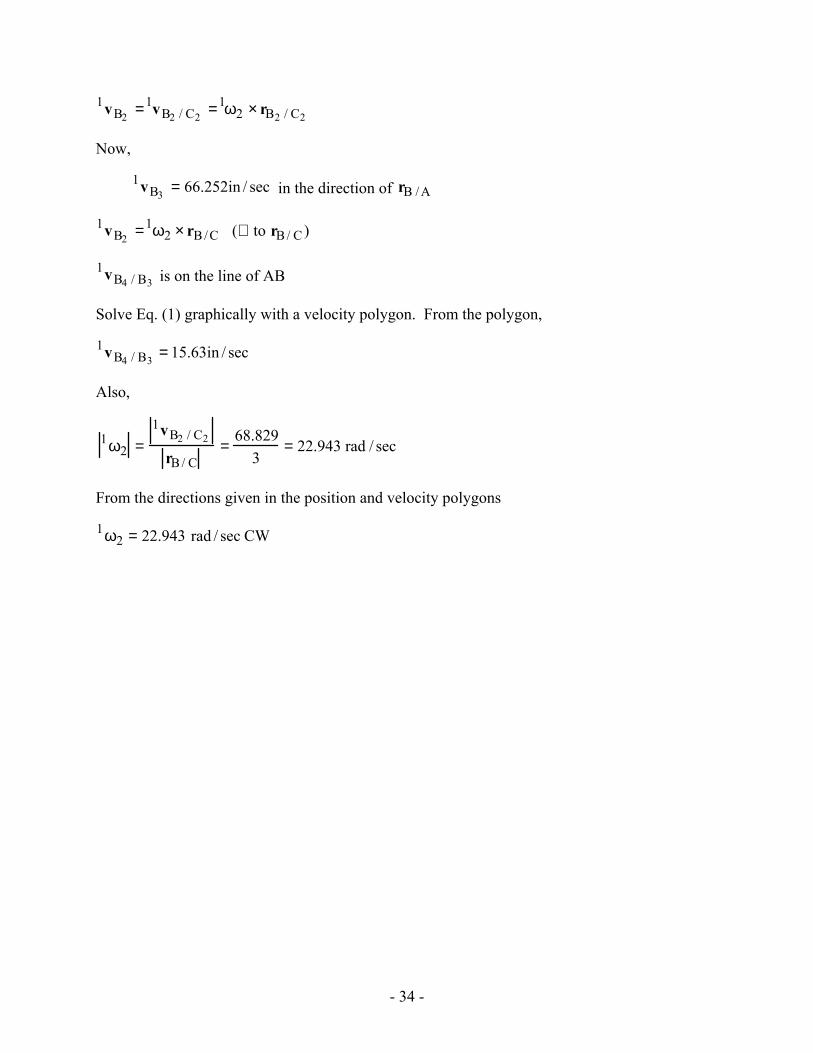
1vB2 =1vB2 / C2 =1ω2 × rB2 / C2
Now,
1vB3 = 66.252in / sec in the direction of rB /A
1vB2 =1ω2 × rB /C (⊥ to rB / C)
1vB4 / B3 is on the line of AB
Solve Eq. (1) graphically with a velocity polygon. From the polygon,
1vB4 / B3 = 15.63in / sec
Also,
1ω2 =1vB2 / C2
rB / C=
68.8293
= 22.943 rad / sec
From the directions given in the position and velocity polygons
1ω2 = 22.943 rad / sec CW
- 35 -
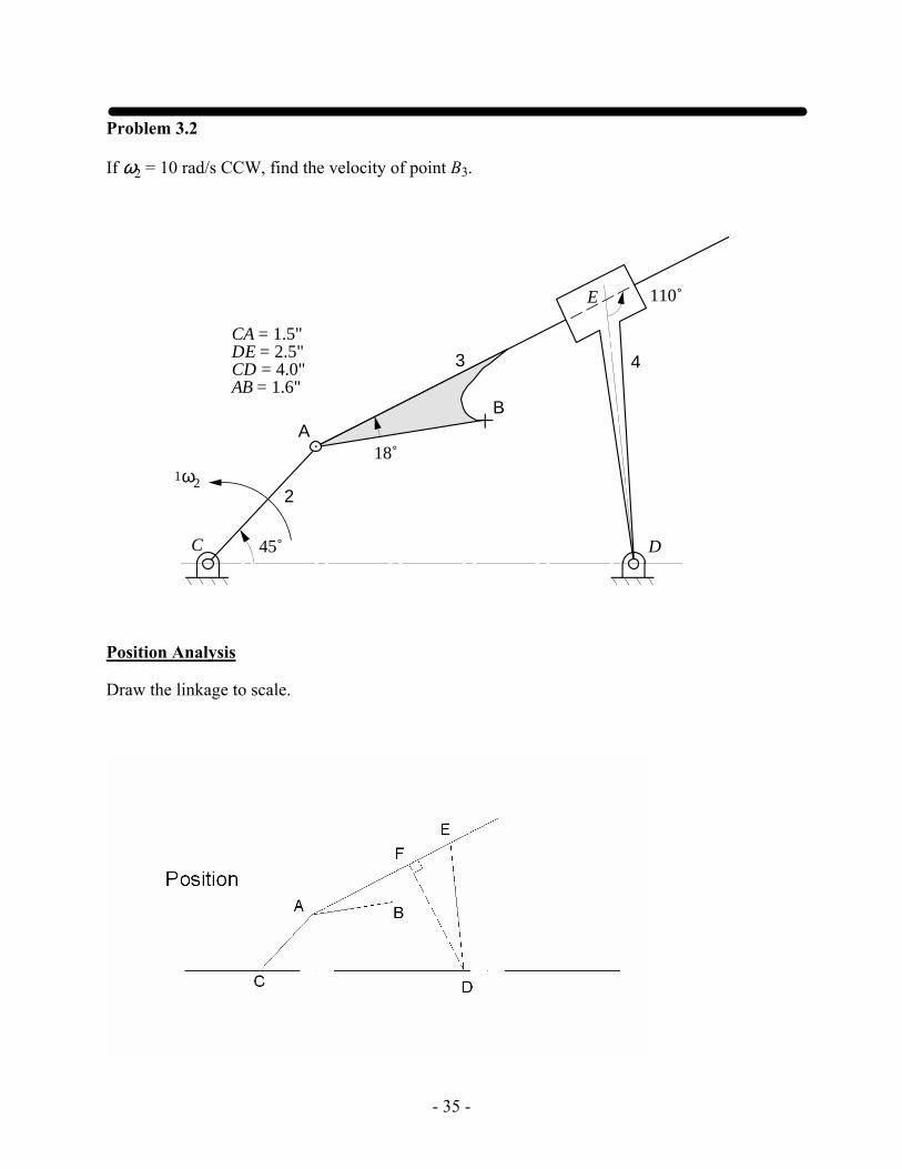
Problem 3.2
If ω2 = 10 rad/s CCW, find the velocity of point B3.
1ω2
ΑΒ
2
3 4
E
C D45˚
18˚
110˚
CA = 1.5"DE = 2.5"CD = 4.0"AB = 1.6"
Position Analysis
Draw the linkage to scale.
- 36 -
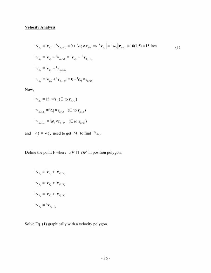
Velocity Analysis
2 2 2 2 2
1 1 1 1 1 1/ 2 / 2 /0 10(1.5) 15 in/sA C A C A C A A Cω ω= + = + × ⇒ = = =v v v r v r (1)
3 3 3 3 2 3 3
1 1 1 1 1/ /E A E A A E A= + = +v v v v v
3 4 3 4
1 1 1/E E E E= +v v v
4 4 4 4
1 1 1 1/ 4 /0E D E D E Dω= + = + ×v v v r
Now,
2
1 15 /sA in=v /( to )A C⊥ r
3 3
1 1/ 3 / /( to )E A E A E Aω= × ⊥v r r
4 4
1 1/ 4 / /( )E D E D E Dtoω= × ⊥v r r
and 3 4ω ω= , need to get 3ω to find 3
1Bv .
Define the point F where AF DF⊥ in position polygon.
3 3 3 3
1 1 1/F A F A= +v v v
3 4 3 4
1 1 1/F F F F= +v v v
4 3 4 3
1 1 1/F F F F= +v v v
4 4 4
1 1/F F D=v v
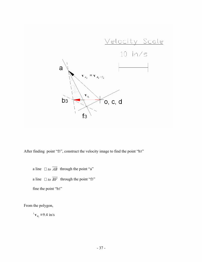
Solve Eq. (1) graphically with a velocity polygon.
- 37 -
After finding point “f3”, construct the velocity image to find the point “b3”
a line to AB⊥ through the point “a”
a line to BF⊥ through the point “f3”
fine the point “b3”
From the polygon,
3
1 9.4 in/sB =v
- 38 -
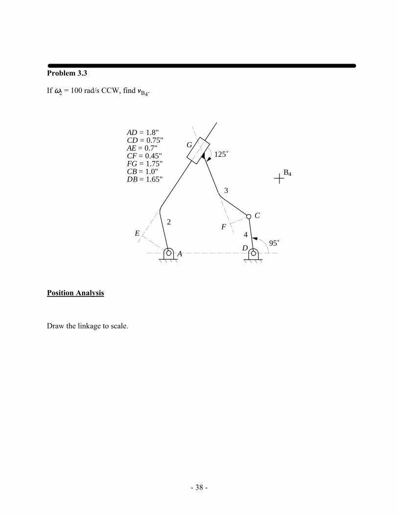
Problem 3.3
If ω2 = 100 rad/s CCW, find vB4.
A
B
2
3
4
C
D
4
95˚
G
EF
AD = 1.8"CD = 0.75"AE = 0.7"CF = 0.45"FG = 1.75"CB = 1.0"DB = 1.65"
125˚
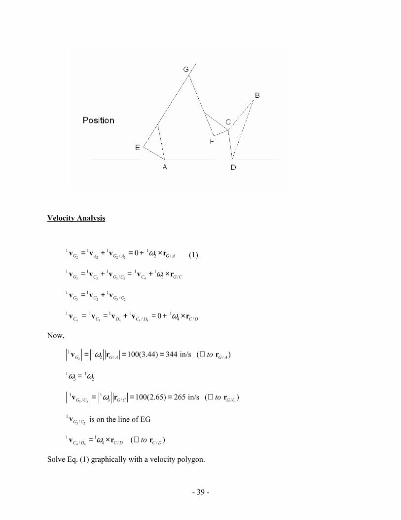
Position Analysis
Draw the linkage to scale.
- 39 -
Velocity Analysis
2 2 2 2
1 1 1 1/ 2 /0G A G A G Aω= + = + ×v v v r (1)
3 3 3 3 4
1 1 1 1 1/ 3 /G C G C C G Cω= + = + ×v v v v r
3 2 3 2
1 1 1/G G G G= +v v v
4 3 4 4 4
1 1 1 1 1/ 4 /0C C D C D C Dω= = + = + ×v v v v r
Now,
2
1 12 / /100(3.44) 344 in/s ( )G G A G Atoω= = = ⊥v r r
1 13 2ω ω=
3 3
1 1/ 3 / /100(2.65) 265 in/s ( )G C G C G Ctoω= = = ⊥v r r
3 2
1/G Gv is on the line of EG
4 4
1 1/ 4 / /( )C D C D C Dtoω= × ⊥v r r
Solve Eq. (1) graphically with a velocity polygon.
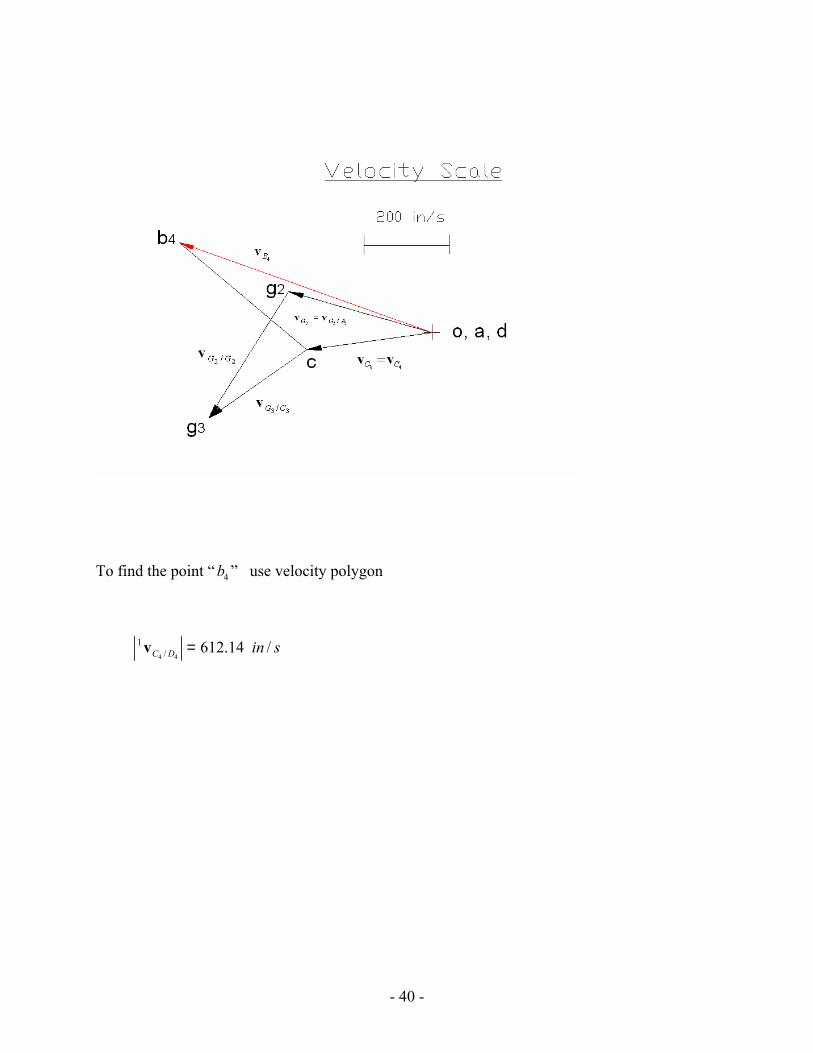
- 40 -
To find the point “ 4b ” use velocity polygon
4 4
1/ 612.14 /C D in s=v
- 41 -
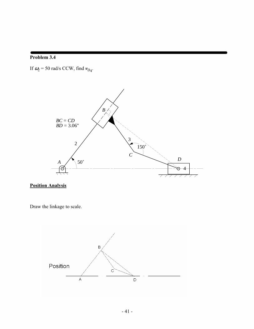
Problem 3.4
If ω2 = 50 rad/s CCW, find vD4.
23
4A
B
CD
50˚
150˚
BC = CDBD = 3.06"
Position Analysis
Draw the linkage to scale.
- 42 -
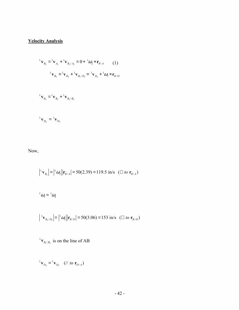
Velocity Analysis
2 2 2 2
1 1 1 1/ 2 /0B A B A B Aω= + = + ×v v v r (1)
3 3 3 3 4
1 1 1 1 1/ 3 /B D B D D B Dω= + = + ×v v v v r
3 2 3 2
1 1 1/B B B B= +v v v
4 3
1 1D D=v v
Now,
2
1 12 / /50(2.39) 119.5 in/s ( )B B A B Atoω= = = ⊥v r r
1 13 2ω ω=
3 3
1 1/ 3 / /50(3.06) 153 in/s ( )B D B D B Dtoω= = = ⊥v r r
3 2
1/B Bv is on the line of AB
4 3
1 1/(// )D D D Ato=v v r
- 43 -
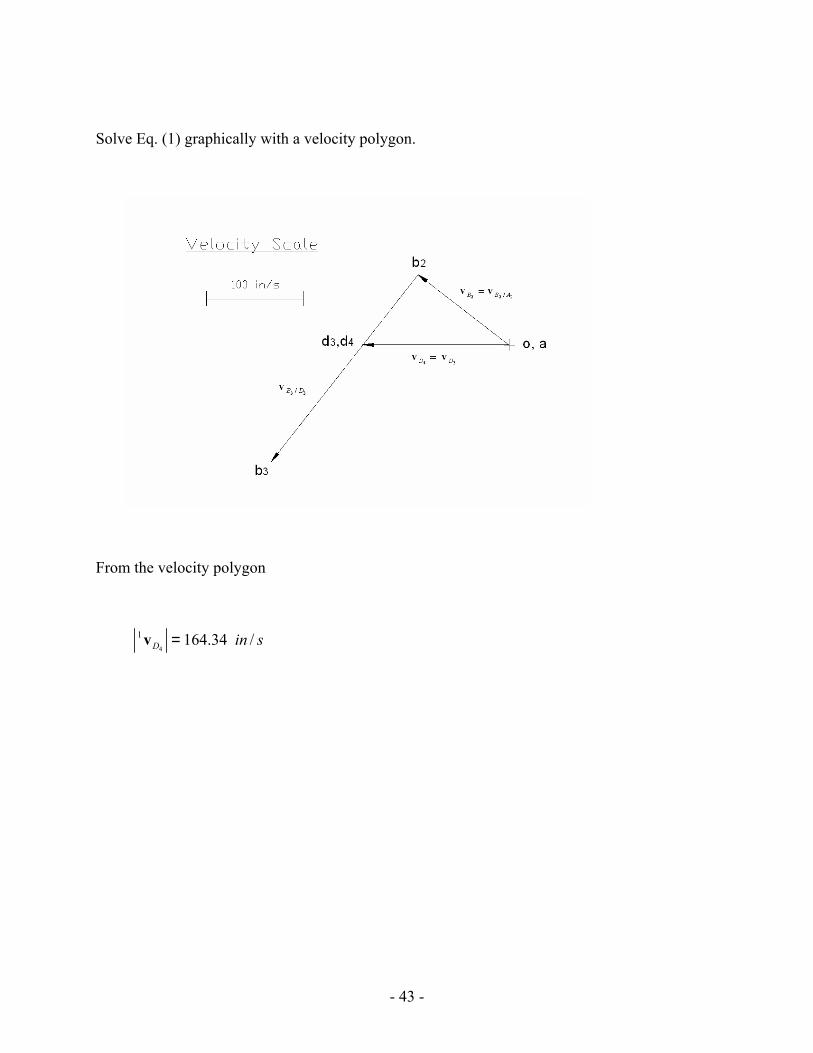
Solve Eq. (1) graphically with a velocity polygon.
From the velocity polygon
4
1 164.34 /D in s=v
- 44 -
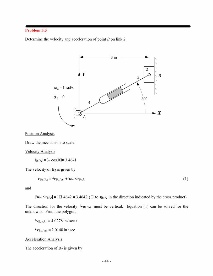
Problem 3.5
Determine the velocity and acceleration of point B on link 2.
2
3
ω4 = 1 rad/s
α 4 = 0
A
B
4
X
Y
3 in
30˚
Position Analysis
Draw the mechanism to scale.
Velocity Analysis
rB/A = 3/ cos30Þ= 3.4641
The velocity of B2 is given by
`1vB2 /A1 = 4vB2/ A1 +1ω4 ×rB/A (1)
and
1ω4 ×rB/ A = 1⋅3.4642 = 3.4642 ( ⊥ to rB/ A in the direction indicated by the cross product)
The direction for the velocity 1vB2 /A1 must be vertical. Equation (1) can be solved for the unknowns. From the polygon,
1vB2 /A1 = 4.0278 in / sec ↑
4vB2/ A1 = 2.0148 in / sec
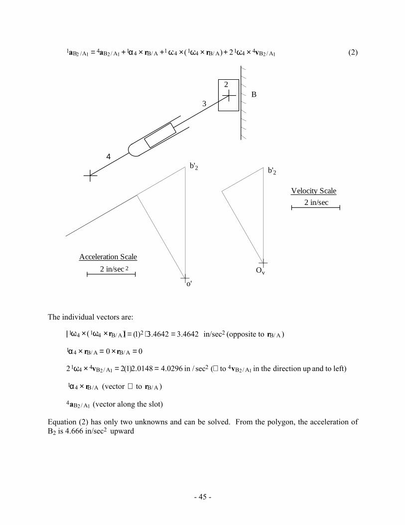
Acceleration Analysis
The acceleration of B2 is given by
- 45 -
1aB2 /A1 = 4aB2/ A1 +1α4 × rB/ A +1 ω4 ×(1ω4 × rB/ A)+ 21ω4 × 4vB2/ A1 (2)
2
3B
4
Ov
2b'
2
o'
2b'
2 in/sec
Velocity Scale
2 in/sec
Acceleration Scale
The individual vectors are:
1ω4 ×(1ω4 ×rB/ A) = (1)2 ⋅3.4642 = 3.4642 in/sec2 (opposite to rB/ A )
1α4 × rB/ A = 0 ×rB/ A = 0
21ω4 × 4vB2/ A1 = 2(1)2.0148 = 4.0296 in / sec2 (⊥ to 4vB2/ A1 in the direction up and to left)
1α4 × rB/A (vector ⊥ to rB/ A )
4aB2/ A1 (vector along the slot)
Equation (2) has only two unknowns and can be solved. From the polygon, the acceleration of B2 is 4.666 in/sec2 upward
- 46 -
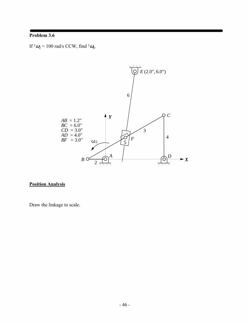
Problem 3.6
If 1ω2 = 100 rad/s CCW, find 1ω6.
2
34
A
C
E (2.0", 6.0")
Y
BD
F
X
5
6
2ω
AB = 1.2"BC = 6.0"CD = 3.0"AD = 4.0"BF = 3.0"
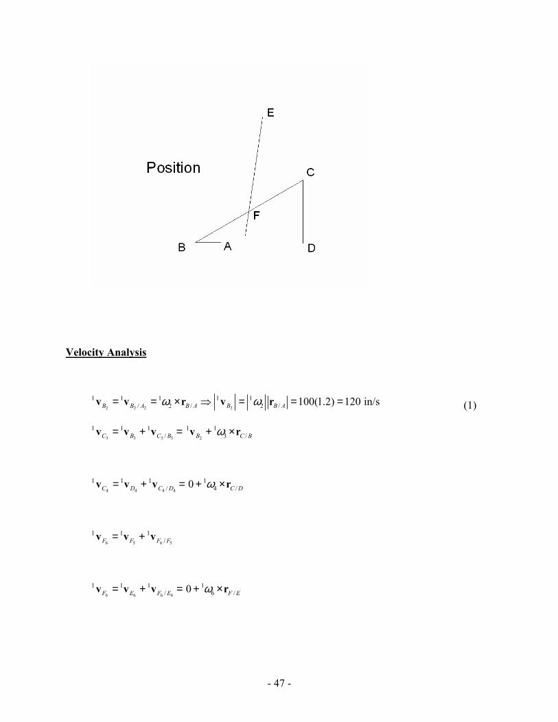
Position Analysis
Draw the linkage to scale.
- 47 -
Velocity Analysis
2 2 2 2
1 1 1 1 1/ 2 / 2 / 100(1.2) 120 in/sB B A B A B B Aω ω= = × ⇒ = = =v v r v r (1)
3 3 3 3 2
1 1 1 1 1/ 3 /C B C B B C Bω= + = + ×v v v v r
4 4 4 4
1 1 1 1/ 4 /0C D C D C Dω= + = + ×v v v r
6 5 6 5
1 1 1/F F F F= +v v v
6 6 6 6
1 1 1 1/ 6 /0F E F E F Eω= + = + ×v v v r
- 48 -
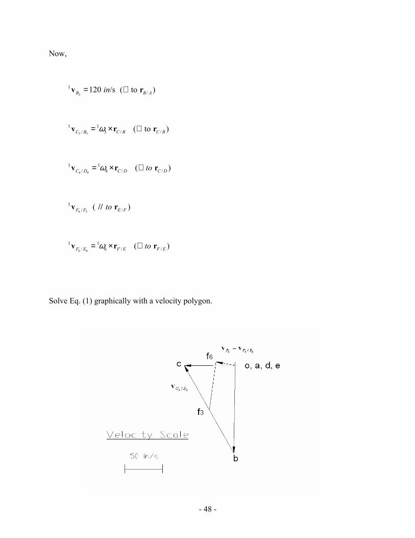
Now,
2
1 120 /sB in=v /( to )B A⊥ r
3 3
1 1/ 3 / /( to )C B C B C Bω= × ⊥v r r
4 4
1 1/ 4 / /( )C D C D C Dtoω= × ⊥v r r
6 5
1/ /( )F F E Ftov // r
6 6
1 1/ 6 / /( )F E F E F Etoω= × ⊥v r r
Solve Eq. (1) graphically with a velocity polygon.
- 49 -
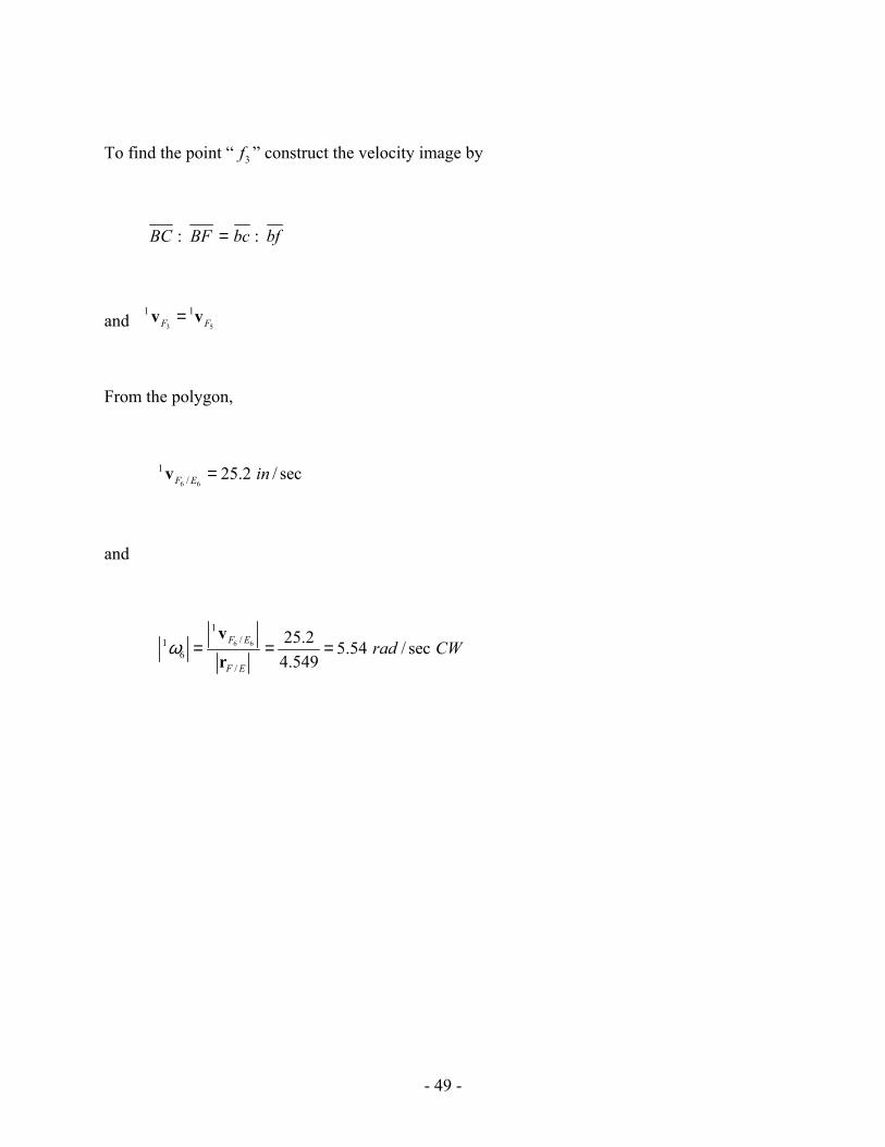
To find the point “ 3f ” construct the velocity image by
: :BC BF bc bf=
and 3 5
1 1F F=v v
From the polygon,
6 6
1/ 25.2 / secF E in=v
and
6 6
1/1
6/
25.2 5.54 / sec4.549
F E
F E
rad CWω = = =vr
- 50 -
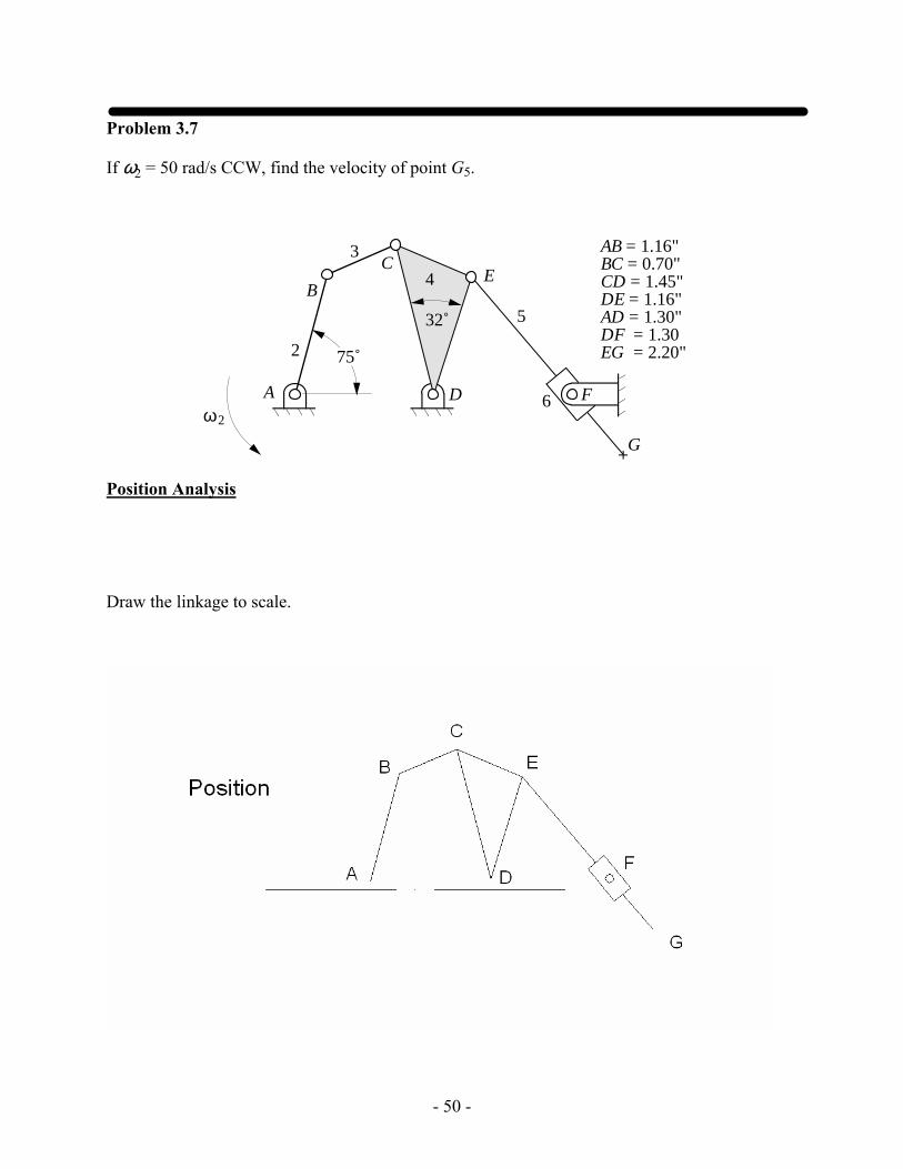
Problem 3.7
If ω2 = 50 rad/s CCW, find the velocity of point G5.
AB = 1.16"BC = 0.70"CD = 1.45"DE = 1.16"AD = 1.30"DF = 1.30EG = 2.20"
ω2
A
C
B
D F
75˚2
3
4
G
E
32˚ 5
6
Position Analysis
Draw the linkage to scale.
- 51 -
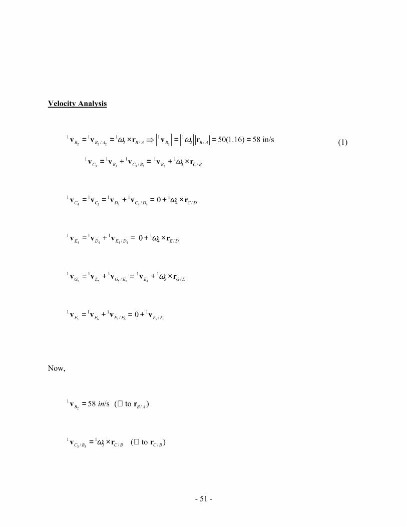
Velocity Analysis
2 2 2 2
1 1 1 1 1/ 2 / 2 / 50(1.16) 58 in/sB B A B A B B Aω ω= = × ⇒ = = =v v r v r (1)
3 3 3 3 2
1 1 1 1 1/ 3 /C B C B B C Bω= + = + ×v v v v r
4 3 4 4 4
1 1 1 1 1/ 4 /0C C D C D C Dω= = + = + ×v v v v r
4 4 4 4
1 1 1 1/ 4 /0E D E D E Dω= + = + ×v v v r
5 5 5 5 4
1 1 1 1 1/ 5 /G E G E E G Eω= + = + ×v v v v r
5 6 5 6 5 6
1 1 1 1/ /0F F F F F F= + = +v v v v
Now,
2
1 58 /sB in=v /( to )B A⊥ r
3 3
1 1/ 3 / /( to )C B C B C Bω= × ⊥v r r
- 52 -
4 4
1 1/ 4 / /( )C D C D C Dtoω= × ⊥v r r
5 5
1 1/ 5 / /( )G E G E G Etoω= × ⊥v r r
5 6
1/ /( )F F G Etov // r
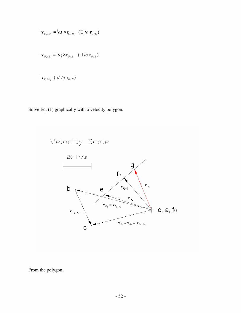
Solve Eq. (1) graphically with a velocity polygon.
From the polygon,
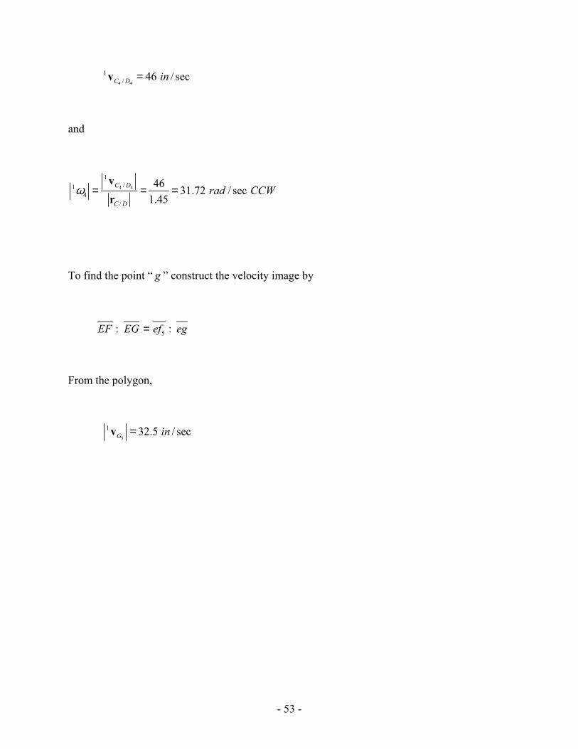
- 53 -
4 4
1/ 46 / secC D in=v
and
4 4
1/1
4/
46 31.72 / sec1.45
C D
C D
rad CCWω = = =vr
To find the point “ g ” construct the velocity image by
5: :EF EG ef eg=
From the polygon,
5
1 32.5 / secG in=v
- 54 -
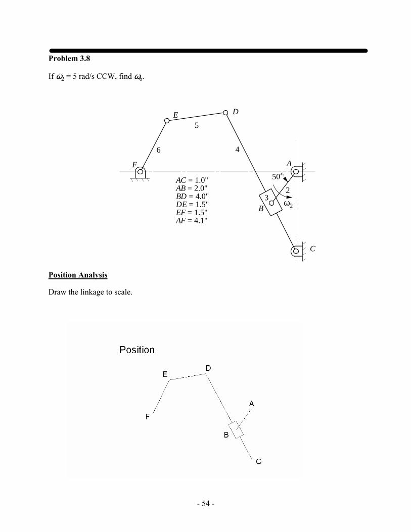
Problem 3.8
If ω2 = 5 rad/s CCW, find ω6.
C
DE
2
ω2
4
5
6
50˚
A
B
F
AC = 1.0"AB = 2.0"BD = 4.0"DE = 1.5"EF = 1.5"AF = 4.1"
3
Position Analysis
Draw the linkage to scale.
- 55 -
Velocity Analysis
2 2 2 2
1 1 1 1 1/ 2 / 2 / 5(1) 5 in/sB B A B A B B Aω ω= = × ⇒ = = =v v r v r (1)
4 3 4 3
1 1 1/B B B B= +v v v
4 4 4 4
1 1 1/B C B C= +v v v
Now,
2
1 5 /sB in=v /( to )B A⊥ r
4 4
1 1/ 4 / /( to )B C B C B Cω= × ⊥v r r
Solve Eq. (1) graphically with a velocity polygon.
/ 1.33B C in=r
From the polygon,
4 4
1/ 4.5 / secB C in=v
and
4 4
1/1
4/
4.5 3.38 / sec1.33
B C
B C
rad CWω = = =vr
With the value of 4ω
4 4 4 4 4
1 1 1 1 1 1/ 4 / 4 / 3.38(3.88) 13.12 in/sD C C D C D D C Dω ω= + = × ⇒ = = =v v v r v r
5 4
1 1D D=v v
5 5 5 5
1 1 1/D E D E= +v v v
6 5
1 1E E=v v
6 6 6 6 6 6
1 1 1 1/ /0E F E F E F= + = +v v v v
- 56 -
5 5
1/ /( )D E D Eto⊥v r
6 6
1/ /( )E F E Fto⊥v r
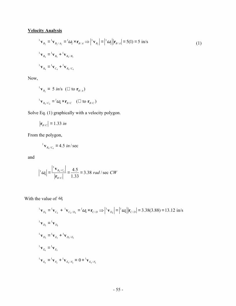
Solve graphically with a velocity polygon.
From the polygon,
6 6
1/ 15.4 / secE F in=v
and
6 6
1/1
6/
15.4 10.267 / sec1.5
E F
E F
rad CWω = = =vr
- 57 -
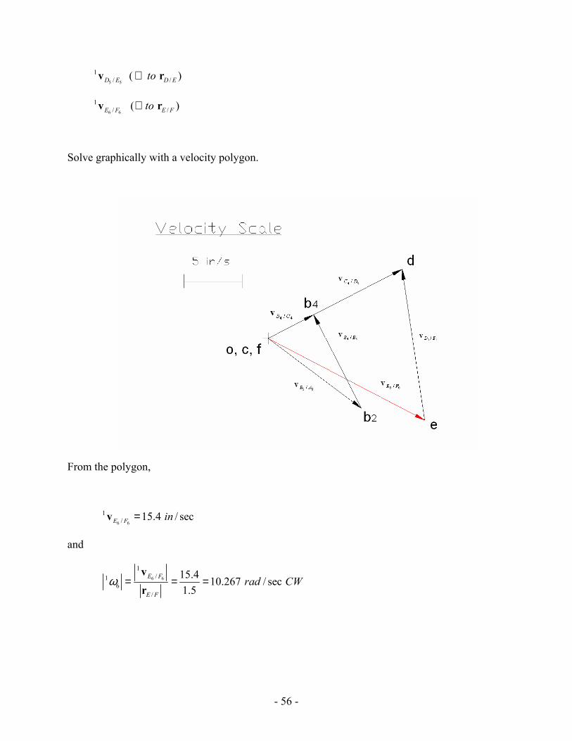
Problem 3.9
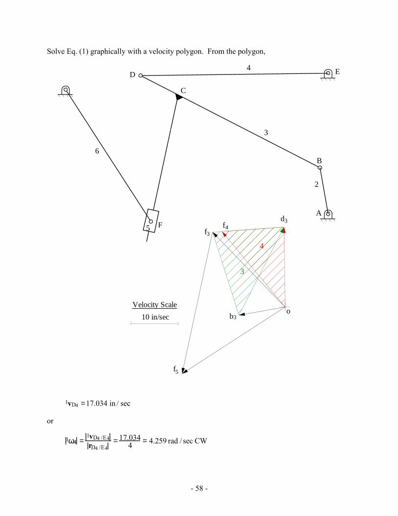
In the mechanism below, ω2 = 10 rad/s. Write the velocity equations and determine the following: vD4, ω4, vF6, ω6.
C
A
B
DE
F
2
4
3
5
6
G (-5.6, 2.65)
X
Y
AB = 1.0 inBD = 4.3 inAE = 3.0 inDE = 4.0 inGF = 3.35 inBC = 3.4 in
75˚
100˚
Position Analysis
Draw the linkage to scale. First locate the pivots A, E, and G. Next draw link 2 and locate B. Then locate point D and point C. Draw the line CF as shown, and finally locate point F.
Velocity Analysis:
1vB3 =1vB2 =1vB2 /A2
1vD4 =1vD3 = 1vD4 /E4 =1vB3 +1vD3/ B3 (1)
1vF5 =1vF6 = 1vF6/ G6 =1vF3 +1vF5/F3 (2)
Now,
1vD4 /E4 =1ω4 × rD4 /E4 ⇒ 1vD4 /E4 = 1ω4 ⋅ rD4/ E4 (⊥ to rD4 /E4)
1vB2 /A2 =1ω2 × rB2/ A2 ⇒ 1vB2/ A2 =1ω2 ⋅ rB2/ A2 =10 ⋅1=10 in / sec (⊥ to rB2 / A2)
1vD3/ B3 =1ω3 × rD3/ B3 ⇒ 1vD3/ B3 = 1ω3 ⋅ rD3/B3 (⊥ to rD3/B3)
- 58 -
Solve Eq. (1) graphically with a velocity polygon. From the polygon,
C
A
B
D E
F
2
4
3
5
6
b3
d3f4
4
f3
f5
o10 in/sec
Velocity Scale
3
1vD4 =17.034 in / sec
or
1ω4 =1vD4 /E4rD4 /E4
= 17.0344 = 4.259 rad / sec CW
- 59 -
Also, using velocity image
1vF4 = 20.994 in / sec
Now,
1vF3 = 22.227 in / sec(using velocity polygon)
1vF6/ G6 =1ω6 × rF6/G6 ⇒ 1vF6/G6 = 1ω6 ⋅ rF6/ G6 (⊥ to rF6/G6)
1vF6/ G6 along the slot
Solve Eq. (2) graphically with a velocity polygon. From the polygon,
1vF6/ G6 = 26.171in / sec
or
1ω6 =1vF6/G6rF6/G6
= 26.1713.35 = 7.812 rad / sec CW
Problem 3.10
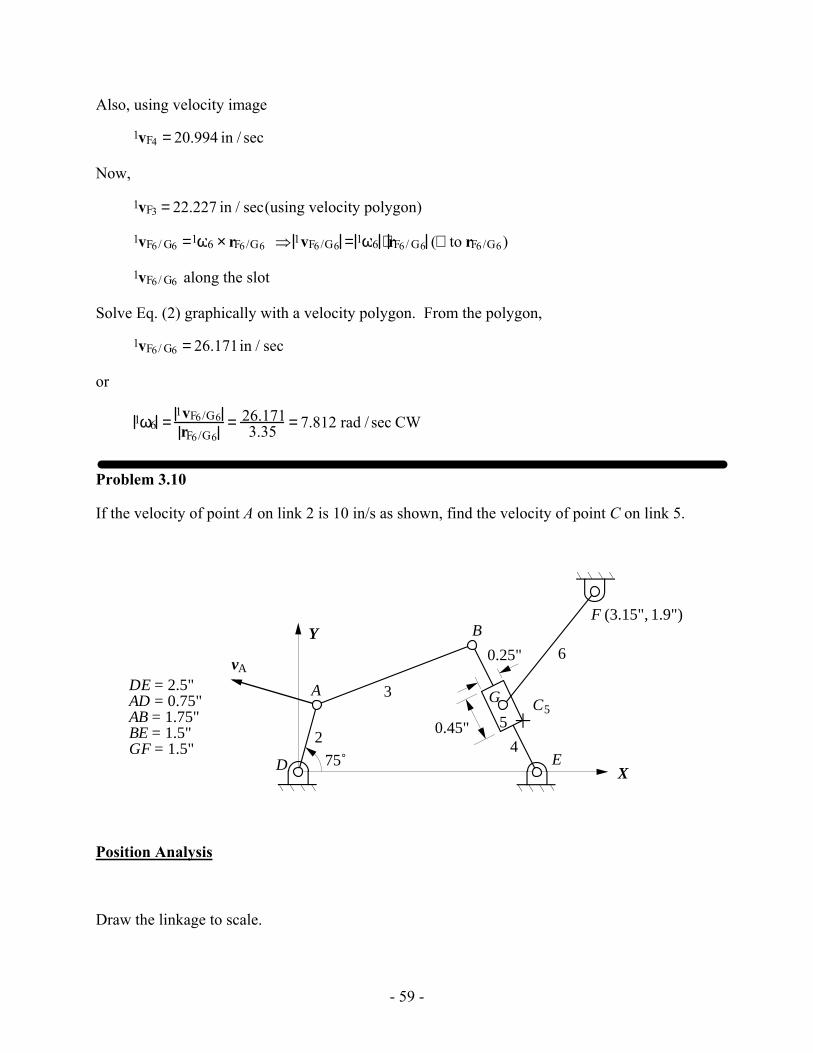
If the velocity of point A on link 2 is 10 in/s as shown, find the velocity of point C on link 5.
2
3
4
6
A5C
B
5
vA
D E
F (3.15", 1.9")
G
5
X
Y
75˚
DE = 2.5"AD = 0.75"AB = 1.75"BE = 1.5"GF = 1.5"
0.45"
0.25"
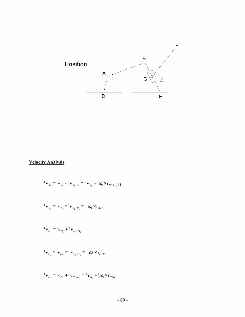
Position Analysis
Draw the linkage to scale.
- 60 -
Velocity Analysis
3 3 3 3 2
1 1 1 1 1/ 3 /B A B A A B Aω= + = + ×v v v v r (1)
4 3 4 4
1 1 1 1/ 4 /B B B E B Eω= = = ×v v v r
5 4 5 4
1 1 5/G G G G= +v v v
6 5 6 6
1 1 1 1/ 6 /G G G F G Fω= = = ×v v v r
5 5 5 5 6
1 1 1 1 1/ 5 /C G C G G C Gω= + = + ×v v v v r
- 61 -
Now,
2
1 10 /sA in=v /( to )A D⊥ r
3 3
1 1/ 3 / /( to )B A B A B Aω= × ⊥v r r
4 4
1 1/ 4 / /( )B E B E B Etoω= × ⊥v r r
5 6
1 1/ 6 / /( )G F G F G Ftoω= × ⊥v r r
5 4
5/ /( )G G B Etov // r
Solve Eq. (1) graphically with a velocity polygon.
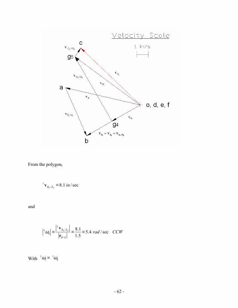
- 62 -
From the polygon,
4 4
1/ 8.1 / secB E in=v
and
4 4
1/1
4/
8.1 5.4 / sec1.5
B E
B E
rad CCWω = = =vr
With 1 15 4ω ω=
- 63 -
5 5
1 1/ 5 / /5.4(0.26) 1.404 in/s ( to )C G C G C Gω= = = ⊥v r r
To find the point “ 4g ” construct the velocity image by
4: :BE EG be eg=
From the polygon,
5
1 10.75 / secC in=v
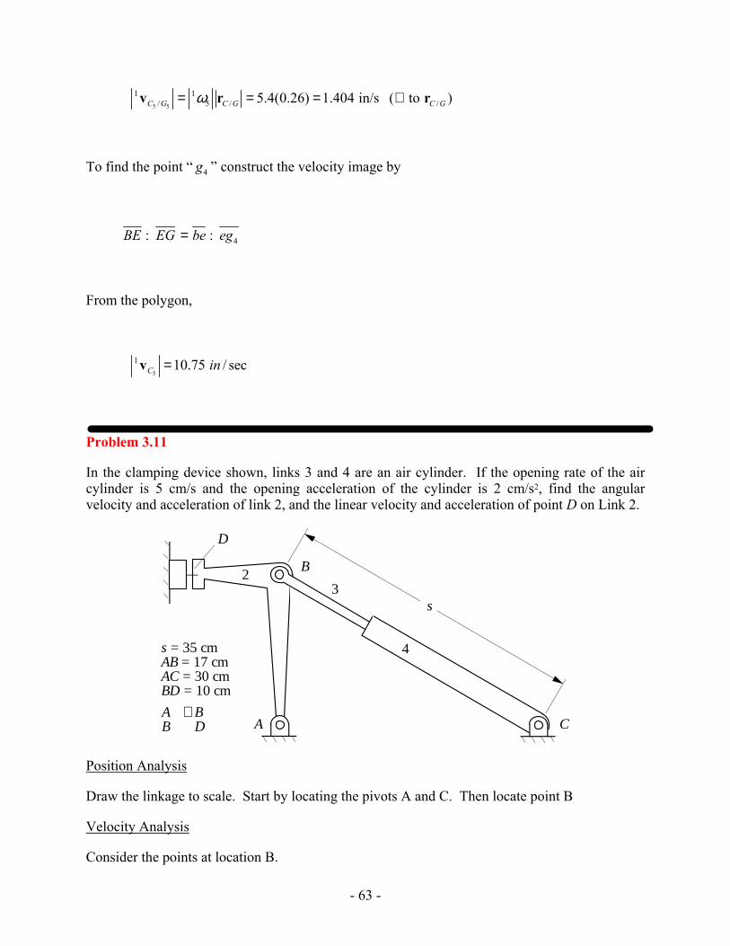
Problem 3.11
In the clamping device shown, links 3 and 4 are an air cylinder. If the opening rate of the air cylinder is 5 cm/s and the opening acceleration of the cylinder is 2 cm/s2, find the angular velocity and acceleration of link 2, and the linear velocity and acceleration of point D on Link 2.
A C
B
D
23
4
s
s = 35 cmAB = 17 cmAC = 30 cmBD = 10 cm
AB
⊥ BD
Position Analysis
Draw the linkage to scale. Start by locating the pivots A and C. Then locate point B
Velocity Analysis
Consider the points at location B.

- 64 -
1vB2 =1vB3 =1vB2/ A2
1vB3 =1vB4 +1vB3/B4 (1)
Where
1vB2/ A2 =1ω2 ×rB/ A (⊥ to rB/ A)
1vB4 =1vB4 /C4 =1ω4 ×rB/C (⊥ to rB/C)
1vB3/B4 = 5 cm / s along rB/C
Solve Eq. (1) using a velocity polygon, and determine the velocity of D2 by image.
1vD2 = 5.79 cm / s
1ω2 =1vB2/ A2
rB/A= 5.81
17 = 0.342 rad / s CCW
and 1ω4 =
1vB4/C4
rB/C= 3.018
35 = 0.0862 rad / s CCW
Acceleration Analysis
Again, consider the points at location B.
1αB2 =1αB3 =1αB2 /A2 =1αB2/A2r +1αB2/A2
t
1αB3 =1αB4/A4 +1αB3 /B4 =1αB4/A4r +1αB4/A4
t +4αB3/B4t +4αB3 /B4
n +1αB3/B4c
Combining the equations,
1αB2/A2r +1αB2/A2
t =1αB4/ A4r +1αB4/ A4
t +4αB3/B4t + 4αB3/B4
n +1αB3/ B4c (2)
Where
1αB2 /A2r = 1ω2
2 rB/A = 0.3422(17) =1.99 cm / s2 (opposite to rB/A)
1αB2 /A2t =1α2 ×rB/A (⊥ to rB/A)
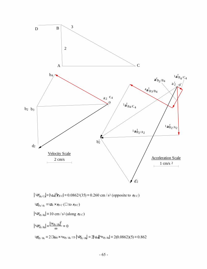
- 65 -
b2’
o'
1 cm/sAcceleration Scale
2
1aB2/A2t
4a B3/B4
1a B4 /C4r
1aB2/A2r
A
B
C
D
2
3
o
2 cm/s
Velocity Scale
b2 b3
b4
c4a2
d2
1a B4 /C4t
a B3 /B4c
ta 2’
d2’
1αB4/C4r = 1ω4
2rB/C = 0.08622(35) = 0.260 cm / s2 (opposite to rB/C)
1αB4/A4t =1α4 ×rB/C (⊥ to rB/C)
4αB3/B4t =10 cm / s2 (along rB/C)
4αB3/B4n =
1vB3 /B42
∞ = 0
1αB3/ B4c = 2 ⋅1ω4 ×4vB3/ B4 ⇒ 1αB3 /B4
c = 21ω4 4vB3/B4 = 2(0.0862)(5) = 0.862
- 66 -
The direction for 1αB3/ B4c is perpendicular to BC and in the direction defined by rotating 4vB3/B4
90˚ in the direction of 1ω4 . This direction is generally down and to the left.
Solve Eq. (2) using an acceleration polygon, and determine the acceleration of D2 by image.
1aD2 = 4.39 cm / s2
1α2 =1αB2/A2
t
rB/A= 3.23
17 = 0.190 rad / s2 CCW
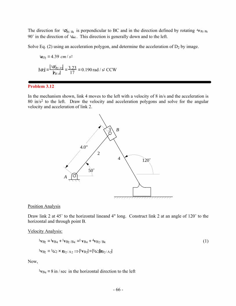
Problem 3.12
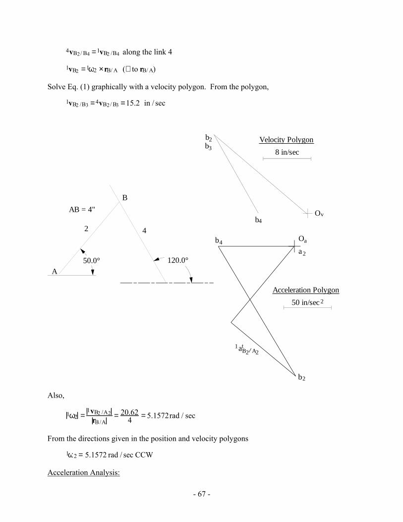
In the mechanism shown, link 4 moves to the left with a velocity of 8 in/s and the acceleration is 80 in/s2 to the left. Draw the velocity and acceleration polygons and solve for the angular velocity and acceleration of link 2.
24
A
B3
120˚
50˚
4.0"
Position Analysis
Draw link 2 at 45˚ to the horizontal lineand 4" long. Construct link 2 at an angle of 120˚ to the horizontal and through point B.
Velocity Analysis:
1vB2 =1vB4 +1vB2 /B4 =1 vB4 + 4vB2/ B4 (1)
1vB2 = 1ω2 × rB2/ A2 ⇒ 1vB2 = 1ω2 rB2/ A2
Now,
1vB4 = 8 in / sec in the horizontal direction to the left
- 67 -
4vB2/ B4 =1vB2 /B4 along the link 4
1vB2 =1ω2 ×rB/ A (⊥ to rB/ A)
Solve Eq. (1) graphically with a velocity polygon. From the polygon,
1vB2 /B3 =4vB2/ B3 =15.2 in / sec
Ovb4
b2
8 in/sec
Velocity Polygon
50.0° 120.0°
A
B
2 4
AB = 4"
Oa
50 in/sec 2
b4
b2
a2
aB21
A2t
Acceleration Polygon
b3
Also,
1ω2 =1vB2 /A2
rB/A= 20.62
4 = 5.1572rad / sec
From the directions given in the position and velocity polygons
1ω2 = 5.1572 rad / sec CCW
Acceleration Analysis:
- 68 -
1aB2 =1aB4 +1aB2/B4 =1 aB4 +4aB2 /B4 + 21ω4 ×4vB2 /B4 (2)
But, 1ω4 = 0 . Therefore,
1aB2 =1aB4 + 4aB2 /B4
Also,
1aB2 =1aB2/A2 =1aB2 /A2t +1 aB2/A2
r
Therefore,
1aB2/A2t +1aB2/A2
r =1aB4 +4aB2 /B4
Now,
1aB4 = 80 in / sec2 in the horizontal direction to the left
4aB2 /B4 is along the link 4
1aB2 /A2r = 1ω2
2 rB/A (opposite to rB/A)
1aB2/A2t =1α2 ×rB/A and is ⊥ to rB/A
From the acceleration polygon,
1aB2/A2t = 89 in / sec2
Therefore,
1α2 =1aB2 /A2
t
rB/A= 89
4 = 22.25 rad / sec2
From the directions given on the acceleration and position polygons, 1α2 = 22.25 rad / sec2 CW
- 69 -
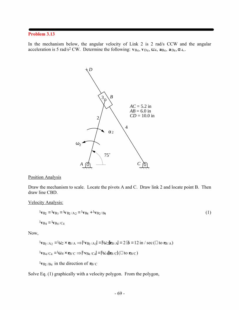
Problem 3.13
In the mechanism below, the angular velocity of Link 2 is 2 rad/s CCW and the angular acceleration is 5 rad/s2 CW. Determine the following: vB4, vD4, ω4, aB4, aD4, α 4,.
A
B
C
D
2
3
4
2ω
2α
75˚
AC = 5.2 inAB = 6.0 inCD = 10.0 in
Position Analysis
Draw the mechanism to scale. Locate the pivots A and C. Draw link 2 and locate point B. Then draw line CBD.
Velocity Analysis:
1vB2 =1vB3 =1vB2 /A2 =1vB4 +1vB2/ B4 (1)
1vB4 =1vB4 /C4
Now,
1vB2 /A2 =1ω2 × rB/A ⇒ 1vB2 /A2 = 1ω2 rB/A = 2 ⋅6 =12 in / sec (⊥ to rB/ A)
1vB4/C4 =1ω4 ×rB/ C ⇒ 1vB4 /C4 = 1ω4 rB/C (⊥ to rB/C)
1vB2 /B4 in the direction of rB/ C
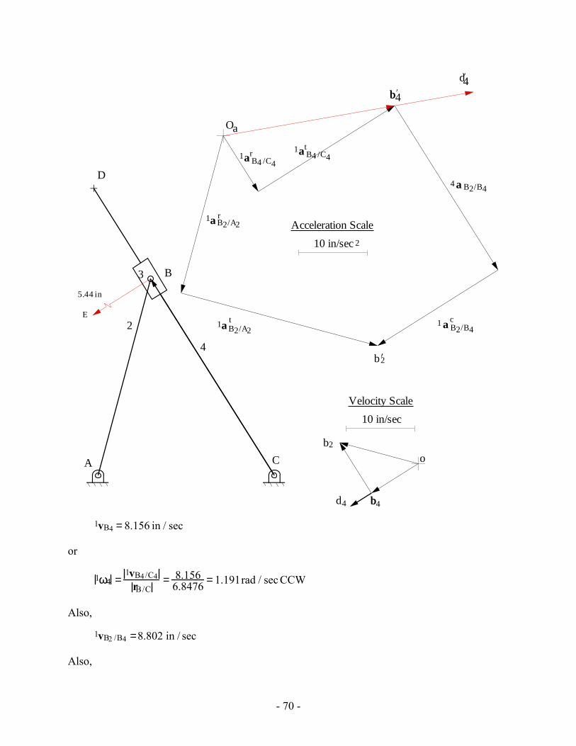
Solve Eq. (1) graphically with a velocity polygon. From the polygon,
- 70 -
A
B
C
D
2
3
4
b2
b4b
o
10 in/sec
Velocity Scale
d4
b2’
b4b’
Oa
10 in/sec
Acceleration Scale
2
1a B2/A2t
1a B4 /C4t
4
1 a B2/B4c
d4’
a B2/B4
1a B4 /C4r
1a B2/A2r
5.44 in
E
1vB4 = 8.156 in / sec
or
1ω4 =1vB4/C4
rB/C= 8.156
6.8476 = 1.191rad / sec CCW
Also,
1vB2 /B4 =8.802 in / sec
Also,
- 71 -
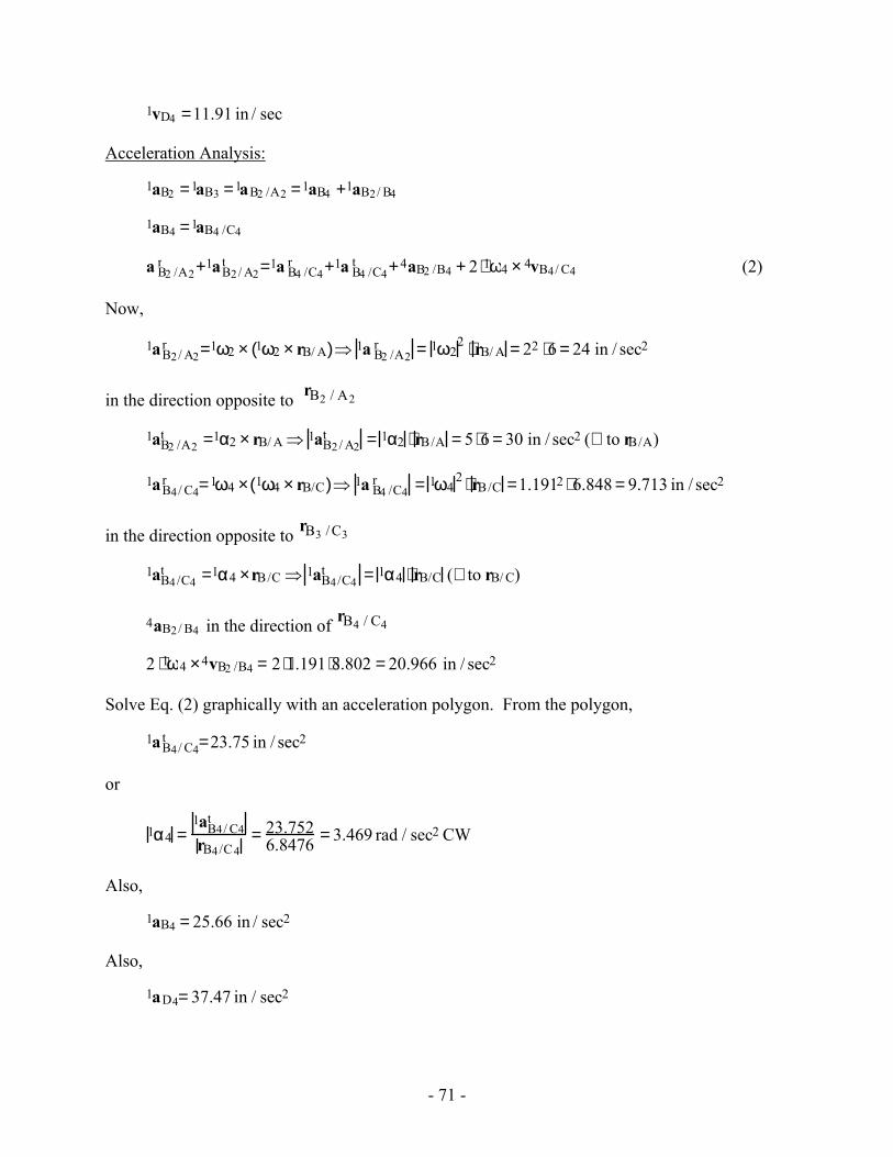
1vD4 =11.91 in / sec
Acceleration Analysis:
1aB2 =1aB3 =1aB2 /A2 =1aB4 +1aB2/ B4
1aB4 =1aB4 /C4
a B2 /A2r +1aB2 / A2
t =1a B4 /C4r +1a B4 /C4
t +4aB2 /B4 + 2 ⋅1ω4 × 4vB4/ C4 (2)
Now,
1aB2/ A2r =1ω2 × 1ω2 × rB/ A( )⇒ 1a B2 /A2
r = 1ω22 ⋅ rB/ A = 22 ⋅6 = 24 in / sec2
in the direction opposite to rB2 / A2
1aB2 /A2t =1α2 × rB/ A ⇒ 1aB2/ A2
t = 1α2 ⋅ rB/A = 5 ⋅6 = 30 in / sec2 (⊥ to rB/A)
1aB4/ C4r =1ω4 × 1ω4 × rB/C( )⇒ 1a B4 /C4
r = 1ω42 ⋅ rB/C =1.1912 ⋅ 6.848 = 9.713 in / sec2
in the direction opposite to rB3 / C3
1aB4/C4t =1α4 ×rB/C ⇒ 1aB4/C4
t = 1α4 ⋅ rB/C (⊥ to rB/ C)
4aB2/ B4 in the direction of rB4 / C4
2 ⋅1ω4 ×4vB2 /B4 = 2 ⋅1.191⋅8.802 = 20.966 in / sec2
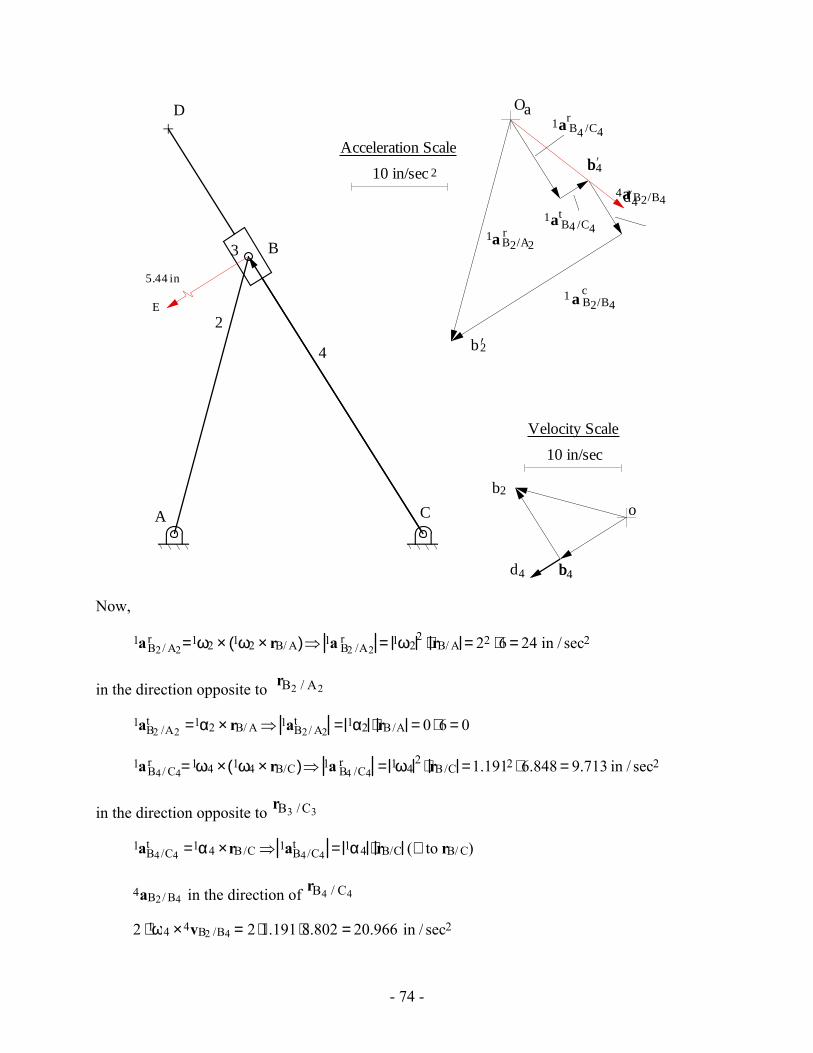
Solve Eq. (2) graphically with an acceleration polygon. From the polygon,
1aB4/ C4t =23.75 in / sec2
or
1α4 =1aB4/ C4
t
rB4/C4= 23.752
6.8476 = 3.469 rad / sec2 CW
Also,
1aB4 = 25.66 in / sec2
Also,
1aD4= 37.47 in / sec2
- 72 -
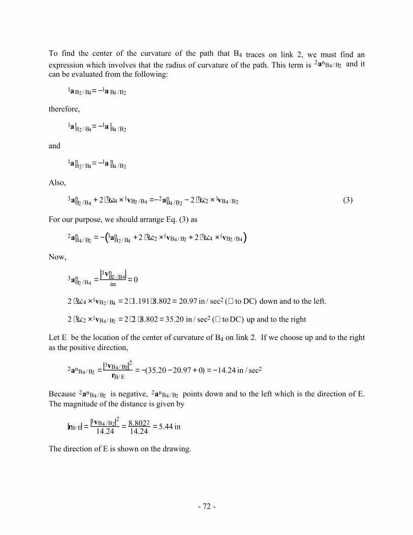
To find the center of the curvature of the path that B4 traces on link 2, we must find an expression which involves that the radius of curvature of the path. This term is 2anB4/ B2 and it can be evaluated from the following:
1aB2/ B4= −1a B4 /B2
therefore,
1aB2/ B4t = −1a B4 /B2
t
and
1aB2/ B4n = −1a B4 /B2
n
Also,
3aB2 /B4n + 2 ⋅1ω4 ×1vB2 /B4 =−2aB4 /B2
n − 2 ⋅1ω2 ×1vB4 /B2 (3)
For our purpose, we should arrange Eq. (3) as
2aB4/ B2n = − 3aB2/ B4
n +2 ⋅1ω2 ×1vB4/ B2 + 2 ⋅1ω4 ×1vB2 /B4( )
Now,
3aB2 /B4n =
3vB2 /B4n
∞ = 0
2 ⋅1ω4 ×1vB2/ B4 = 2 ⋅1.191⋅8.802 = 20.97 in / sec2 (⊥ to DC) down and to the left.
2 ⋅1ω2 ×1vB4/ B2 = 2 ⋅2 ⋅8.802 = 35.20 in / sec2 (⊥ to DC) up and to the right
Let E be the location of the center of curvature of B4 on link 2. If we choose up and to the right as the positive direction,
2anB4/ B2 =1vB4/ B2
2
rB/ E= −(35.20 −20.97 + 0) = −14.24 in / sec2
Because 2anB4/ B2 is negative, 2anB4/ B2 points down and to the left which is the direction of E. The magnitude of the distance is given by
rB/ E =1vB4 /B2
2
14.24 = 8.802214.24 = 5.44 in
The direction of E is shown on the drawing.
- 73 -
Problem 3.14
Resolve Problem 3.13 if ω2 = 2 rad/sec (constant)
Position Analysis
Draw the mechanism to scale. Locate the pivots A and C. Draw link 2 and locate point B. Then draw line CBD.
Velocity Analysis:
1vB2 =1vB3 =1vB2 /A2 =1vB4 +1vB2/ B4 (1)
1vB4 =1vB4 /C4
Now,
1vB2 /A2 =1ω2 × rB/A ⇒ 1vB2 /A2 = 1ω2 rB/A = 2 ⋅6 =12 in / sec (⊥ to rB/ A)
1vB4/C4 =1ω4 ×rB/ C ⇒ 1vB4 /C4 = 1ω4 rB/C (⊥ to rB/C)
1vB2 /B4 in the direction of rB/ C
Solve Eq. (1) graphically with a velocity polygon. From the polygon,
1vB4 = 8.156 in / sec
or
1ω4 =1vB4/C4
rB/C= 8.156
6.8476 = 1.191rad / sec CCW
Also,
1vB2 /B4 =8.802 in / sec
Also,
1vD4 =11.91 in / sec
Acceleration Analysis:
1aB2 =1aB3 =1aB2 /A2 =1aB4 +1aB2/ B4
1aB4 =1aB4 /C4
a B2 /A2r +1aB2/ A2
t =1a B4 /C4r +1a B4 /C4
t +4aB2 /B4 + 2 ⋅1ω4 × 4vB4/ C4 (2)
- 74 -
A
B
C
D
2
3
4
b2
b4b
o
10 in/sec
Velocity Scale
d4
b2’
b4b’
Oa
10 in/sec
Acceleration Scale
2
1a B4 /C4t
1 a B2/B4c
d4’4a B2/B4
1a B4 /C4r
1a B2/A2r
5.44 in
E
Now,
1aB2/ A2r =1ω2 × 1ω2 × rB/ A( )⇒ 1a B2 /A2
r = 1ω22 ⋅ rB/ A = 22 ⋅6 = 24 in / sec2
in the direction opposite to rB2 / A2
1aB2 /A2t =1α2 × rB/ A ⇒ 1aB2/ A2
t = 1α2 ⋅ rB/A = 0 ⋅ 6 = 0
1aB4/ C4r =1ω4 × 1ω4 × rB/C( )⇒ 1a B4 /C4
r = 1ω42 ⋅ rB/C =1.1912 ⋅ 6.848 = 9.713 in / sec2
in the direction opposite to rB3 /C3
1aB4/C4t =1α4 ×rB/C ⇒ 1aB4/C4
t = 1α4 ⋅ rB/C (⊥ to rB/ C)
4aB2/ B4 in the direction of rB4 / C4
2 ⋅1ω4 ×4vB2 /B4 = 2 ⋅1.191 ⋅8.802 = 20.966 in / sec2
- 75 -
Solve Eq. (2) graphically with an acceleration polygon. From the polygon,
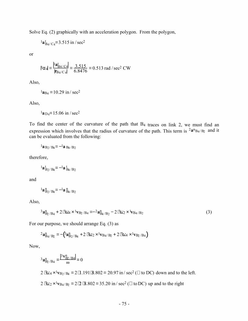
1aB4/ C4t =3.515 in / sec2
or
1α4 =1aB4/ C4
t
rB4/C4= 3.515
6.8476 = 0.513 rad / sec2 CW
Also,
1aB4 =10.29 in / sec2
Also,
1aD4=15.06 in / sec2
To find the center of the curvature of the path that B4 traces on link 2, we must find an expression which involves that the radius of curvature of the path. This term is 2anB4/ B2 and it can be evaluated from the following:
1aB2/ B4= −1a B4 /B2
therefore,
1aB2/ B4t = −1a B4 /B2
t
and
1aB2/ B4n = −1a B4 /B2
n
Also,
3aB2 /B4n + 2 ⋅1ω4 ×1vB2 /B4 =−2aB4 /B2
n − 2 ⋅1ω2 ×1vB4 /B2 (3)
For our purpose, we should arrange Eq. (3) as
2aB4/ B2n = − 3aB2/ B4
n +2 ⋅1ω2 ×1vB4/ B2 + 2 ⋅1ω4 ×1vB2 /B4( )
Now,
3aB2 /B4n =
3vB2 /B4n
∞ = 0
2 ⋅1ω4 ×1vB2/ B4 = 2 ⋅1.191⋅8.802 = 20.97 in / sec2 (⊥ to DC) down and to the left.
2 ⋅1ω2 ×1vB4/ B2 = 2 ⋅2 ⋅8.802 = 35.20 in / sec2 (⊥ to DC) up and to the right
- 76 -
Let E be the location of the center of curvature of B4 on link 2. If we choose up and to the right as the positive direction,
2anB4/ B2 =1vB4/ B2
2
rB/ E= −(35.20 −20.97 + 0) = −14.24 in / sec2
Because 2anB4/ B2 is negative, 2anB4/ B2 points down and to the left which is the direction of E. The magnitude of the distance is given by
rB/ E =1vB4 /B2
2
14.24 = 8.802214.24 = 5.44 in
The direction of E is shown on the drawing. Note that the location of E does not depend on the acceleration of link 2.
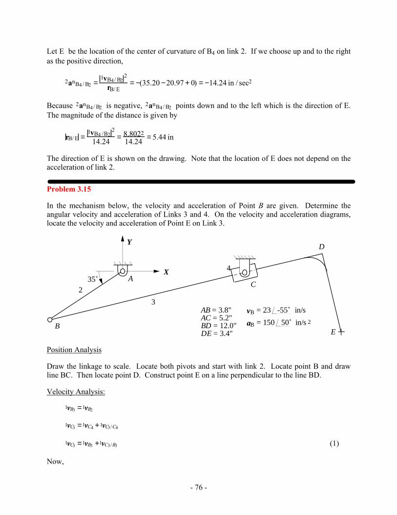
Problem 3.15
In the mechanism below, the velocity and acceleration of Point B are given. Determine the angular velocity and acceleration of Links 3 and 4. On the velocity and acceleration diagrams, locate the velocity and acceleration of Point E on Link 3.
2
3
4A
C
D
BE
35˚
AB = 3.8"AC = 5.2"BD = 12.0"DE = 3.4"
X
Y
-55˚v B = 23 in/s
50˚a B = 150 in/s 2
Position Analysis
Draw the linkage to scale. Locate both pivots and start with link 2. Locate point B and draw line BC. Then locate point D. Construct point E on a line perpendicular to the line BD.
Velocity Analysis:
1vB3 =1vB2
1vC3 =1vC4 +1vC3/C4
1vC3 =1vB3 +1vC3/B3 (1)
Now,
- 77 -
1vC3 =1vC3/C4 in the direction of rC3/B3
1vC3 /B3 =1ω3 × rC3/B3⇒ 1vC3 /B3 = 1ω3 ⋅ rC3/B3 (⊥ to rC3/ B3)
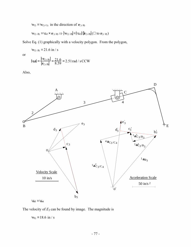
Solve Eq. (1) graphically with a velocity polygon. From the polygon,
1vC3 /B3 = 21.6 in / s or
1ω3 =1vC3/B3
rC3/B3= 21.6
8.59 = 2.51rad / sCCW
Also,
b3
c3
o
10 in/s
Velocity Scale
2
3 4
AC
D
B Ed3 b3’
c3’
o'50 in/s
Acceleration Scale
2
1aC3/C4c
4 aC3 /C4
1 aB3
1aC3/B3r
1aC3/B3t
d3'
e3'
e3
1ω3 =1ω4
The velocity of E3 can be found by image. The magnitude is
1vE3 =18.6 in / s
- 78 -
Acceleration Analysis:
1aB2 =1aB3
1aC3 =1aC4 +1aC3/C4
1aC3 = 4aC3/C4 + 2 ⋅1ω4 × 4vC3/C4
1aC3 =1aB3 +1aC3/B3
4aC3/C4 + 2 ⋅1ω4 × 4vC3/C4 =1aB3 +1aC3/B3r +1 aC3/B3
t (2)
Now,
4aC3/C4 in the direction of rC3/B3
2 ⋅1ω4 ×1vC3/C4 = 2 ⋅2.51⋅ 21.6 =108 in / s2
1aC3/B3r =1ω3 × 1ω3 ×rC3/B3( )⇒ 1aC3/B3
r = 1ω32 ⋅ rC3/B3 = 2.512 ⋅8.59 = 54.1 in / s2
1aC3/B3t =1α3 × rC3 /B3 ⇒ 1aC3/B3
t = 1α3 ⋅ rC3/B3 (⊥ to rC3/B3)
Solve Eq. (2) graphically with an acceleration polygon. From the polygon,
1aC3/B3t = 43.2 in / s2
or
1α3 =1aC3/B3
t
rC3/B3= 43.2
8.59 = 5.03 rad / s2
Also, 1α3 = 1α4
The acceleration of point E3 is given by image. The magnitude is
1aE3 = 149 in / s2
- 79 -
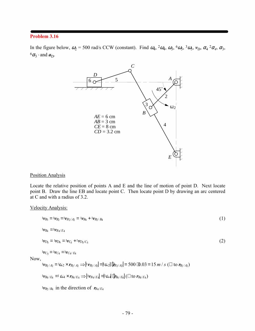
Problem 3.16
In the figure below, ω2 = 500 rad/s CCW (constant). Find ω4, 2ω4, ω3, 6ω5, 3ω5, vD, α4 2α4, α3, 6α5 , and aD.
D
C
2
6 5
ω2
4
A
E
3
B
45˚
AE = 6 cmAB = 3 cmCE = 8 cmCD = 3.2 cm
Position Analysis
Locate the relative position of points A and E and the line of motion of point D. Next locate point B. Draw the line EB and locate point C. Then locate point D by drawing an arc centered at C and with a radius of 3.2.
Velocity Analysis:
1vB3 =1vB2 =1vB2/A2 = 1vB4 +1vB2/ B4 (1)
1vB4 =1vB4/E4
1vD5 = 1vD6 =1vC5 +1vD5/C5 (2)
1vC5 =1vC4 =1vC4/ E4 Now, 1vB2 /A2 =1ω2 ×rB2/ A2 ⇒ 1vB2 /A2 =1ω2 ⋅ rB2/A2 = 500 ⋅0.03 =15 m / s (⊥ to rB2 /A2)
1vB4 /E4 =1ω4 ×rB4/E4 ⇒ 1vB4/E4 =1ω4 ⋅ rB4 /E4 (⊥ to rB4/E4)
1vB2 /B4 in the direction of rB4/E4
- 80 -
D
C
2
5
4
A
E
B
b4b
b2
o
2.5 m/s
Velocity Polygon
c5
d5
1a B4 / E4r
b2’
b4b'’
o'
2000 m/s
Acceleration Polygon
2 c4’
d5'
1aD5/C5r
1aD5
1aD5/C5t
4aB2/B4
c1aB2/B4
r1aB2/A2
t1aB4 /E4
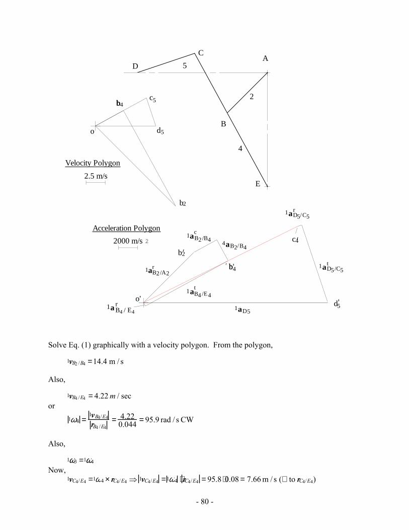
Solve Eq. (1) graphically with a velocity polygon. From the polygon,
1vB2 /B4 =14.4 m / s
Also,
1vB4 /E4 = 4.22 m / sec or
1ω4 =1vB4/E4
rB4 /E4= 4.22
0.044 = 95.9 rad / s CW
Also,
1ω3 =1ω4 Now, 1vC4/E4 =1ω4 × rC4/E4 ⇒ 1vC4/E4 =1ω4 ⋅ rC4/E4 = 95.8 ⋅0.08 = 7.66 m / s (⊥ to rC4/E4)
- 81 -
1vD5 in horizontal direction
1vD5/C5 =1ω5 × rD5/C5 ⇒ 1vD5 /C5 =1ω5 ⋅ rD5/C5 (⊥ to rD5/C5)
Solve Eq. (2) graphically with a velocity polygon. From the polygon,
1vD5/C5 = 3.88 m / s or
1ω5 =1vD5 /C5
rD5/C5= 3.88
0.032 = 121rad / s CCW
And, 1vD5 =1vD6 = 3.18 m / s
For the relative angular velocities,
2ω4 =1ω4 −1ω2 = 95.8CW − 500 CCW = 595.8 CW
6ω5 =1ω5 −1ω6 = 121CCW −0 =121CCW
3ω5 =1ω5 −1ω3 =121CCW − 95.8 CW = 216.8 CCW
Acceleration Analysis:
1aB3 =1aB2 =1aB2 /A2 =1aB4 +1aB2/ B4
1aB4 =1aB4/E4
1aB2 /A2r +1aB2 /A2
t =1aB4 /E4r +1aB4/ E4
t +4aB2 /B4 +2 ⋅1ω4 ×4vB2/B4 (3)
1aD5 =1aD6 =1aC5 +1aD5 /C5
1aC5 =1aC4 =1aC4 /E4
1aD5 =1aC4 /E4r +1aC4/E4
t +1a D5/C5r +1aD5/C5
t (4)
Now,
1aB2 /A2r =1ω2 × 1ω2 ×rB2/ A2( )⇒ 1aB2/A2
r = 1ω22 ⋅ rB2/ A2 = 5002 ⋅0.03 = 7500 m / s2
in the direction opposite to rB2/ A2
1aB2/A2t =1α2 × rB2 /A2 ⇒ 1aB2/A2
t = 1α2 ⋅ rB2/ A2 = 0
1aB4 /E4r =1ω4 × 1ω4 × rB4/E4( )⇒ 1aB4/E4
r = 1ω42 ⋅ rB4 /E4 = 95.82 ⋅0.044 = 404 m / s2
in the direction opposite to rB4 /E4
1aB4/E4t =1 α4 × rB4/E4 ⇒ 1aB4/E4
t = 1α4 ⋅ rB4 /E4 (⊥ to rB4/E4)
- 82 -
4aB2/B4 in the direction opposite to rB4 /E4
1aB2 /B4c = 2 ⋅1 ω4 ×4vB2/ B4 = 2 ⋅ 95.8 ⋅14.4 = 2760 m / s2 (⊥ to rB4 /E4 )
Solve Eq. (3) graphically with an acceleration polygon. From the polygon,
1aB4/E4t = 9960 m / s2
or
1α4 =1aB4/E4
t
rB4 /E4= 9960
0.044 = 226,000 rad / s2 CW
Also, 2α4 =1α4 −1α2 = 226,000 − 0 = 226,000 rad / s2 CW And, 1α4 =1α3
Also, using acceleration image
1aC4 =18,100 m / s2 Now, 1aD5 in horizontal direction
1aD5/C5r =1ω5 × 1ω5 × rD5/C5( )⇒ 1a D5/C5
r = 1ω52 ⋅ rD5/C5 =1212 ⋅0.032 = 470 m / s2
in the direction of -rD5/C5
1aD5/C5t =1α5 × rD5/C5 ⇒ 1aD5/C5
t = 1α5 ⋅ rD5/C5 (⊥ to rD5/C5)
Solve Eq. (4) graphically with an acceleration polygon. From the polygon,
1aD5/C5t = 8640 m / s2
or
1α5 =1aD5/C5
t
rD5 /C5= 8640
0.032 = 270,000 rad / s2 CCW
Also, 6α5 =1α5 −1α6 = 270,000 CCW − 0 = 270,000 rad / s2 CCW And, 3α5 =1α5 −1α3 = 270,000 CCW −226,000CW = 496,000 rad / s2 CCW
Also,
1aD5 =19,400 m / s2
Problem 3.17
In the mechanism below, the angular velocity of Link 2 is 60 rpm CCW (constant). Determine the acceleration of Point C6 and the angular velocity of Link 6.
- 83 -
2
3
A
C
D
B
4
5
62ω
AB = 3.6 ftBD = 9.3 ftAC = 6 ft
45˚
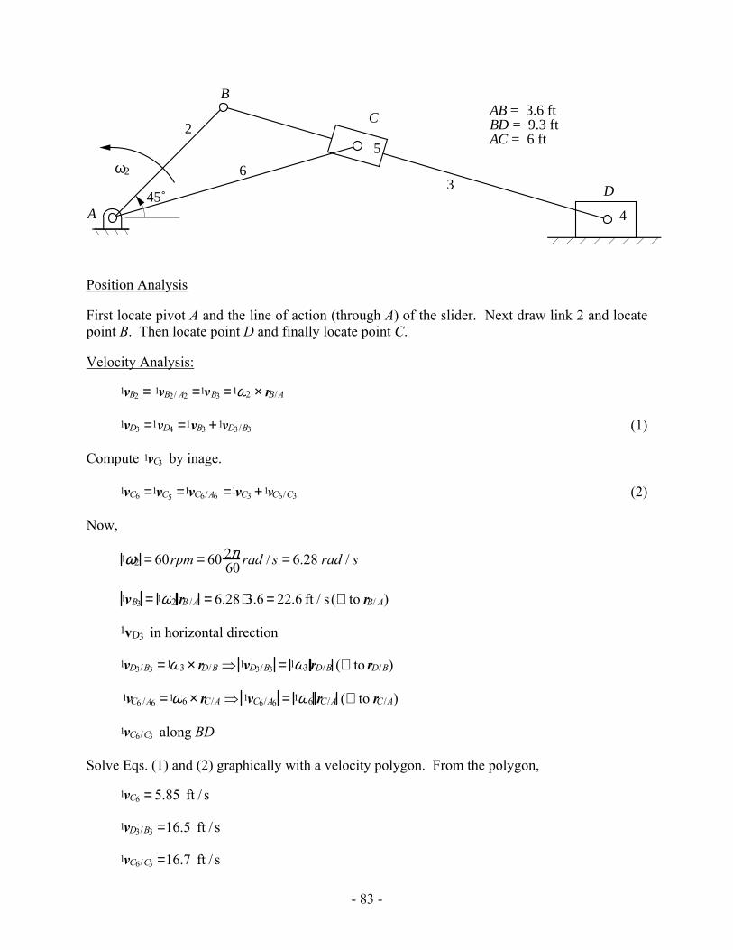
Position Analysis
First locate pivot A and the line of action (through A) of the slider. Next draw link 2 and locate point B. Then locate point D and finally locate point C.
Velocity Analysis:
1vB2 = 1vB2/ A2 =1vB3 =1ω2 × rB/A
1vD3 =1vD4 =1vB3 +1vD3/B3 (1)
Compute 1vC3 by inage.
1vC6 =1vC5 =1vC6/A6 =1vC3 +1vC6/C3 (2)
Now,
1ω2 = 60rpm = 60 2π60 rad / s = 6.28 rad / s
1vB3 = 1ω2 rB /A = 6.28 ⋅3.6 = 22.6 ft / s (⊥ to rB/ A)
1vD3 in horizontal direction
1vD3/B3 =1ω3 × rD/B ⇒ 1vD3/B3 = 1ω3 rD/B (⊥ to rD/B)
1vC6 /A6 =1ω6 × rC/A ⇒ 1vC6/A6 = 1ω6 rC/A (⊥ to rC/A)
1vC6/C3 along BD
Solve Eqs. (1) and (2) graphically with a velocity polygon. From the polygon,
1vC6 = 5.85 ft / s
1vD3/B3 =16.5 ft / s
1vC6/C3 =16.7 ft / s
- 84 -
and 1ω3 =
1vD3/ B3
rD/B= 16.5
9.3 = 1.77 rad / s CW
Acceleration Analysis:
1aB2 = 1aB2/ A2 = 1aB3 = 1aB2/A2r +1aB2 /A2
t
1aD3 =1aD4 =1aB3 +1aD3/B3 = 1aB3 + 1aD3/B3r +1aD3/B3
t (3)
Compute 1aC3 by image.
1aC6 = 1aC5 = 1aC6/ A6 = 1aC3 +1aC5/C3 or 1aC6/A6
r +1aC6/ A6t = 1aC3 + 1aC5/C3
c + 3aC5/C3t + 3aC5/C3
n (4)
Now,
1aD3 in horizontal direction
- 85 -
10 ft/s
Velocity Scale
50 ft/s
Acceleration Scale2
2 3
6
A
B
C
D
b3
od3
c3
c6
b3’
o'
1aC6/C3c
3aC6 /C3
1 aB3
1aC6/A6r
c3’
d3'
c6’
1aC6/A6t
1aC6
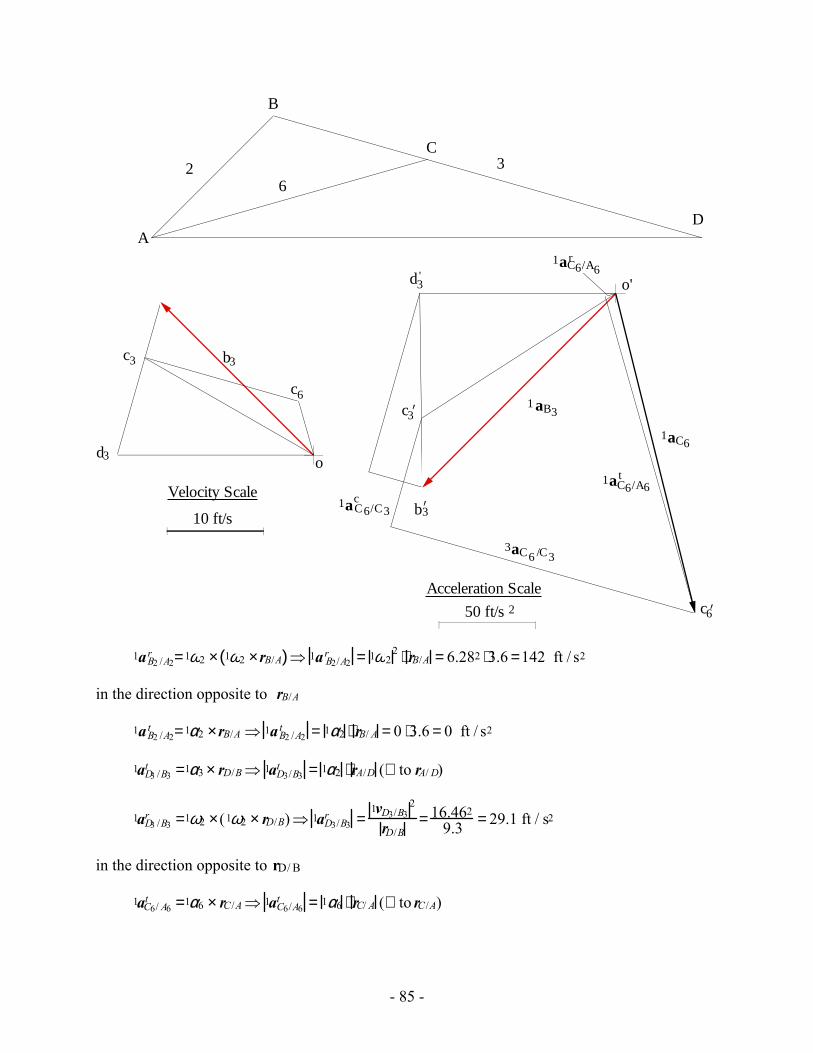
1aB2 /A2r =1ω2 × 1ω2 ×rB/A( )⇒ 1a B2/A2
r = 1ω22 ⋅ rB/A = 6.282 ⋅3.6 =142 ft / s2
in the direction opposite to rB/A
1aB2 /A2t =1α2 ×rB/A ⇒ 1aB2 /A2
t = 1α2 ⋅ rB/ A = 0 ⋅3.6 = 0 ft / s2
1aD3 /B3t =1α3 × rD/B⇒ 1aD3/B3
t = 1α2 ⋅ rA/D (⊥ to rA/ D)
1aD3 /B3r =1ω2 ×(1ω2 × rD/B)⇒ 1aD3/B3
r =1vD3/B3
2
rD/B= 16.462
9.3 = 29.1 ft / s2
in the direction opposite to rD/ B
1aC6/ A6t =1α6 × rC/A⇒ 1aC6/A6
t = 1α6 ⋅ rC/ A (⊥ to rC/A)
- 86 -
1aC6/ A6r =1ω6 ×(1ω6 × rC/ A)⇒ 1aC6/A6
r =1vC6 /A6
2
rC/ A= 5.852
6 = 5.70 ft / s2
in the direction opposite to rC/ A
1aC5/C3c = 2 ⋅1ω3 ×3vC5/C3 ⇒ 1aC5 /C3
c = 21ω3 ⋅ 3vC5/C3 = 2(1.77)(16.66) = 58.97 ft / s2
in the direction perpendicular to BD and in the direction obtained by rotating 3vC5 /C3 90˚ in the direction of 1ω3. The direction is shown on the acceleration polygon.
3aC5 /C3t is along the slide(line BD)
3aC5/C3n =
1vC5/C3
∞ = 0
Solve Eqs. (3) and (4) graphically with an acceleration polygon. From the polygon,
1aC6 =172 ft / s2 Also,
1α6 =1aC6 /A6
t
rC /A= 171
6 = 28.5 rad / s2 CW
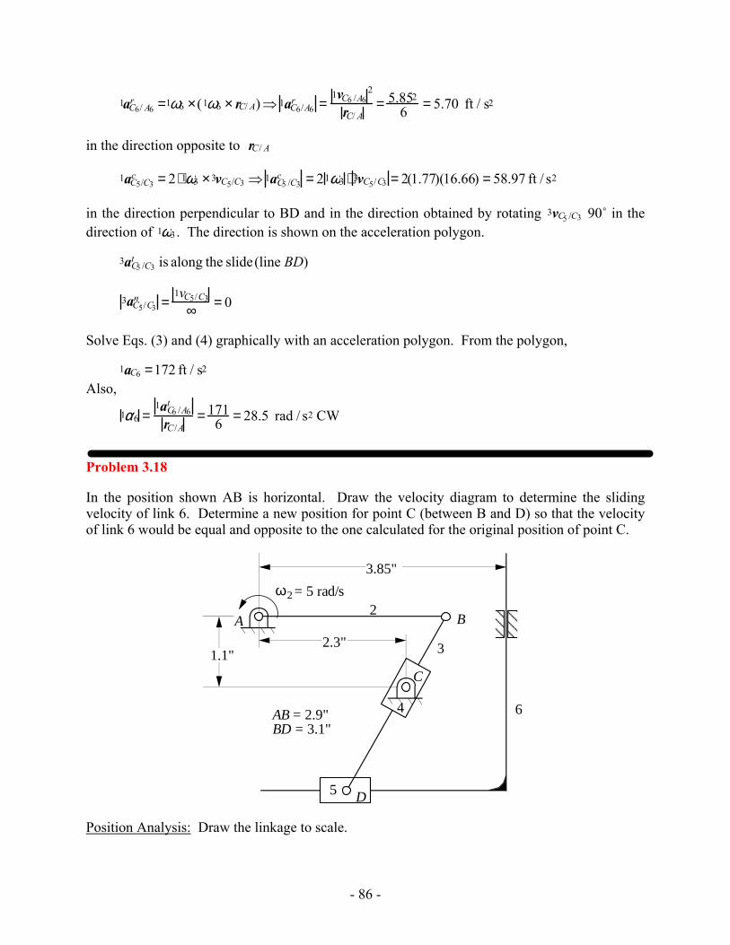
Problem 3.18
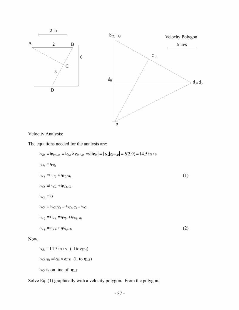
In the position shown AB is horizontal. Draw the velocity diagram to determine the sliding velocity of link 6. Determine a new position for point C (between B and D) so that the velocity of link 6 would be equal and opposite to the one calculated for the original position of point C.
��
= 5 rad/sω2
2
3
4
5
6
C
B
D
3.85"
AB = 2.9"BD = 3.1"
2.3"1.1"
A
Position Analysis: Draw the linkage to scale.
- 87 -
2 in
5 in/s
Velocity Polygon
o
b 2 b3,
c 3
d3 d5,d6
A B
C
D
2
3
6
Velocity Analysis:
The equations needed for the analysis are:
1vB2 =1vB2 /A2 =1ω2 ×rB2/ A2 ⇒ 1vB2 = 1ω2 rB2/A2 = 5(2.9) =14.5 in / s
1vB3 =1vB2
1vC3 =1 vB3 +1vC3/B3 (1)
1vC3 =1 vC4 +1vC3/C4
1vC4 = 0
1vC3 = 1vC3/C4 = 4vC3/C4 = 4vC3
1vD3 =1vD5 =1vB3 +1vD3/ B3
1vD5 =1vD6 +1vD5/D6 (2)
Now,
1vB2 =14.5 in / s (⊥ to rB/A)
1vC3 /B3 =1ω3 × rC /B (⊥ to rC /B)
1vC3 is on line of rC /B
Solve Eq. (1) graphically with a velocity polygon. From the polygon,
- 88 -
1vC3 /B3 = 6.90 in / s
or
1ω3 =1vC3/B3
rC /B= 6.90
1.37 = 5.04 rad / s
From the directions given in the position and velocity polygons
1ω3 = 5.04rad / s CCW
Also,
1vC3 =1vC3/C4 =12.6 in / s
Using velocity image theorem,
1vD3 =1vD5 =15.25 in / s
Now,
1vD6 is on the vertical axis,
1vD5/D6 is on the horizantal axis.
Solve Eq. (2) graphically with a velocity polygon. From the polygon,
1vD6 = 6.85 in / s also, 1vD5/D6 = 13.62 in / s
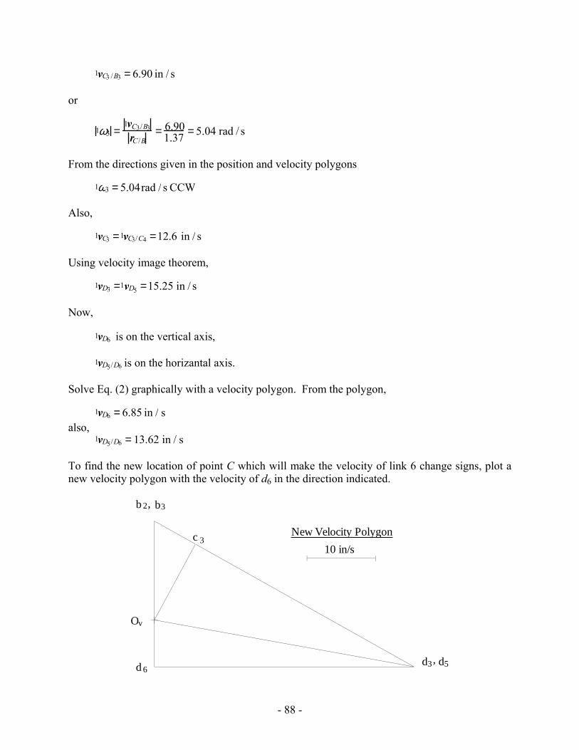
To find the new location of point C which will make the velocity of link 6 change signs, plot a new velocity polygon with the velocity of d6 in the direction indicated.
10 in/s
New Velocity Polygon
Ov
b 2 b3,
c 3
d3 d5,d 6
- 89 -
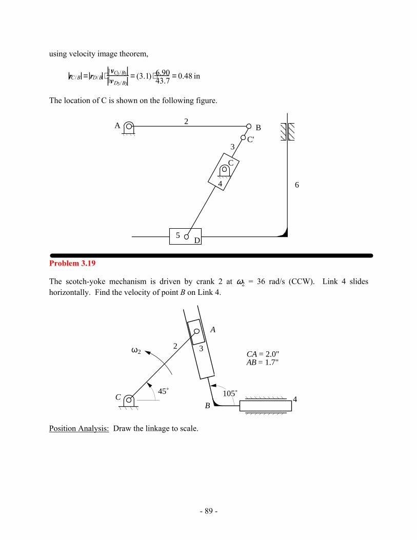
using velocity image theorem,
rC /B = rD/B ⋅1vC3/B31vD3/B3
= (3.1) ⋅ 6.9043.7 = 0.48 in
The location of C is shown on the following figure.
��
����
2
3
5
6
A B
D
C'
4
C
Problem 3.19
The scotch-yoke mechanism is driven by crank 2 at ω2 = 36 rad/s (CCW). Link 4 slides horizontally. Find the velocity of point B on Link 4.
A
B
2
4
3ω2
C45˚ 105˚
CA = 2.0"AB = 1.7"
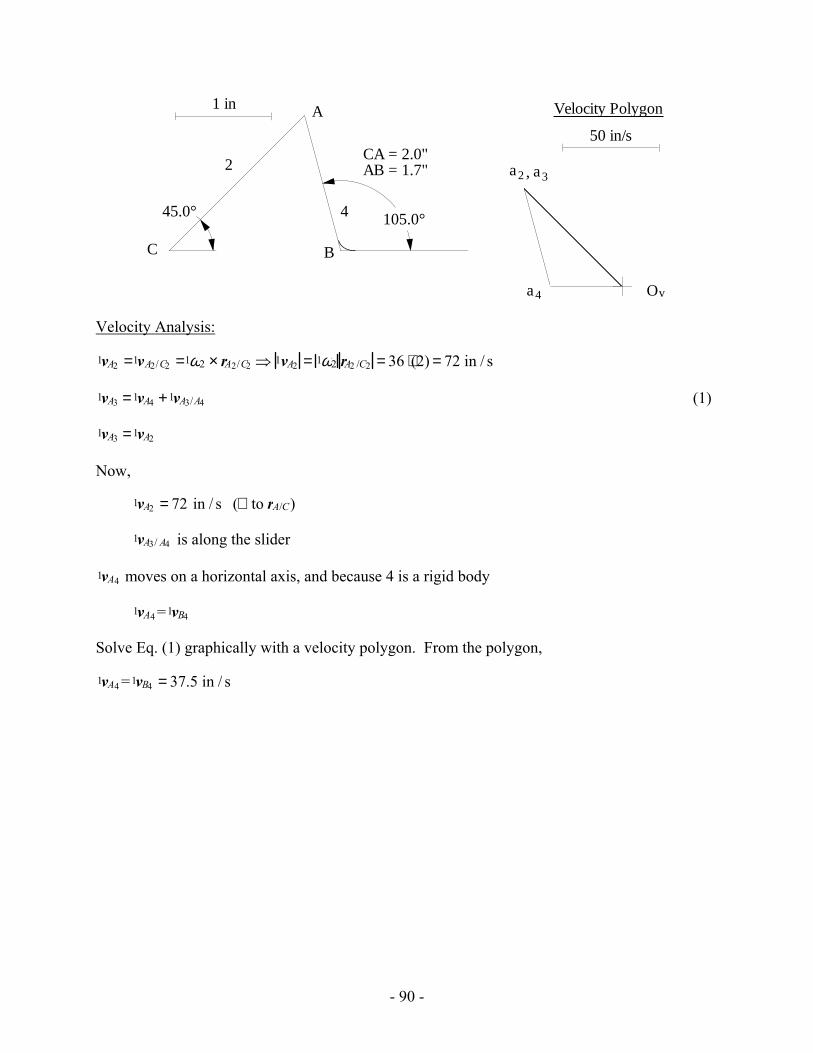
Position Analysis: Draw the linkage to scale.
- 90 -
CA = 2.0"AB = 1.7"
C
A
B
2
4
1 in
45.0° 105.0°
50 in/s
Velocity Polygon
Ov
a2
a4
a3,
Velocity Analysis:
1vA2 =1vA2/C2 =1ω2 × rA2/C2 ⇒ 1vA2 = 1ω2 rA2 /C2 = 36 ⋅(2) = 72 in / s
1vA3 =1vA4 +1vA3/A4 (1)
1vA3 =1vA2
Now,
1vA2 = 72 in / s (⊥ to rA/C)
1vA3/ A4 is along the slider
1vA4 moves on a horizontal axis, and because 4 is a rigid body
1vA4 =1vB4
Solve Eq. (1) graphically with a velocity polygon. From the polygon,
1vA4 =1vB4 = 37.5 in / s
- 91 -
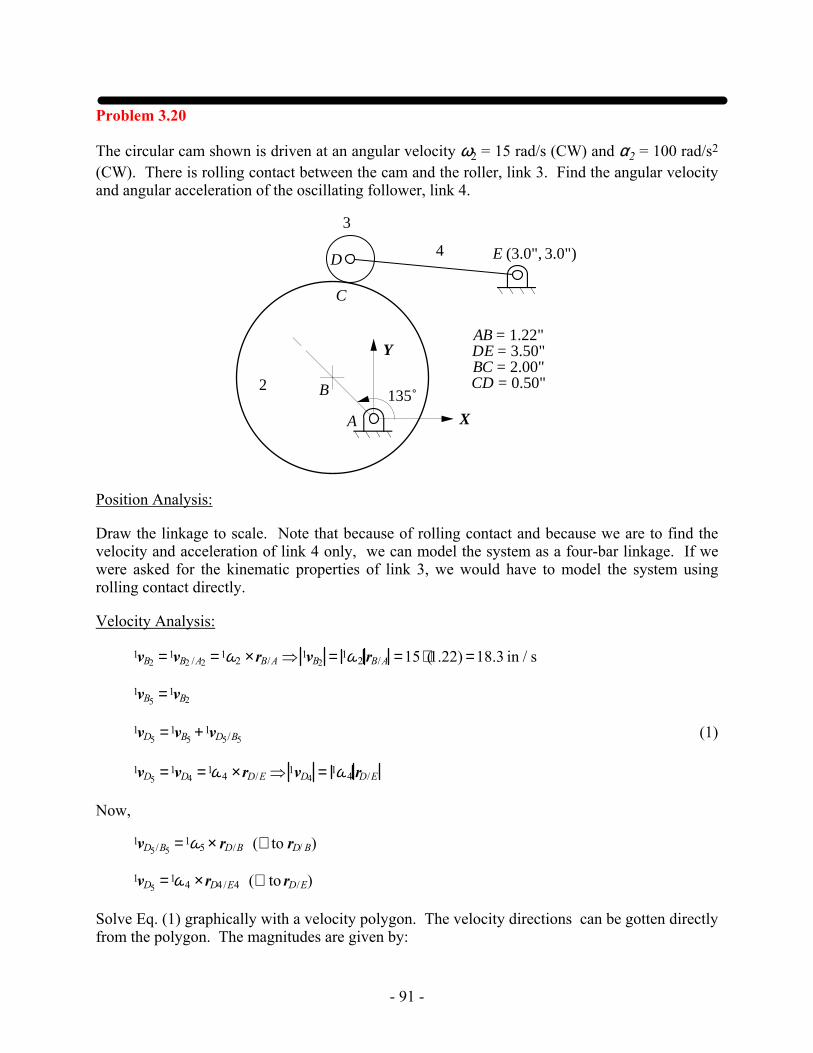
Problem 3.20
The circular cam shown is driven at an angular velocity ω2 = 15 rad/s (CW) and α2 = 100 rad/s2 (CW). There is rolling contact between the cam and the roller, link 3. Find the angular velocity and angular acceleration of the oscillating follower, link 4.
AB = 1.22"DE = 3.50"BC = 2.00"CD = 0.50"B2
4
3
A
C
D E (3.0", 3.0")
135˚
X
Y
Position Analysis:
Draw the linkage to scale. Note that because of rolling contact and because we are to find the velocity and acceleration of link 4 only, we can model the system as a four-bar linkage. If we were asked for the kinematic properties of link 3, we would have to model the system using rolling contact directly.
Velocity Analysis:
1vB2 =1vB2 /A2 =1ω2 ×rB/A ⇒ 1vB2 = 1ω2 rB/A =15 ⋅(1.22) =18.3 in / s
1vB5 =1vB2
1vD5 =1vB5 +1vD5/B5 (1)
1vD5 =1vD4 =1ω4 ×rD/E ⇒ 1vD4 = 1ω4 rD/E
Now,
1vD5/B5 =1ω5 × rD/B (⊥ to rD/ B)
1vD5 =1ω4 ×rD4 /E4 (⊥ to rD/E)
Solve Eq. (1) graphically with a velocity polygon. The velocity directions can be gotten directly from the polygon. The magnitudes are given by:
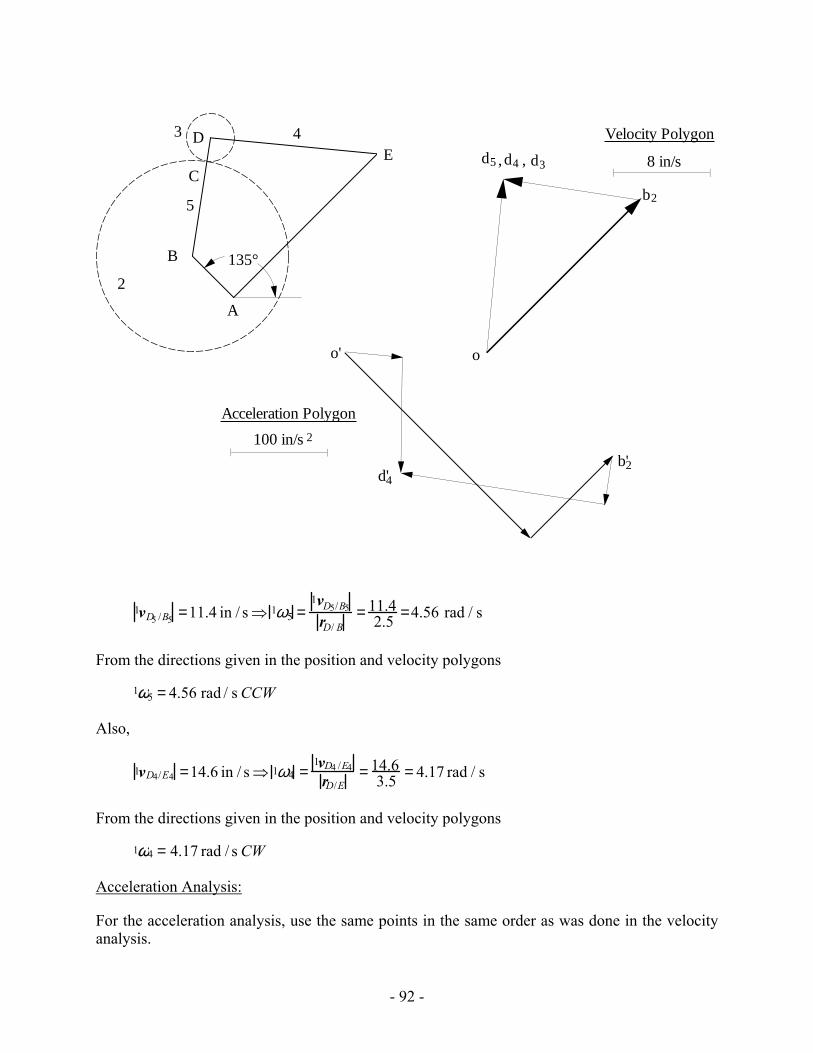
- 92 -
o
b2
d5 d4,
100 in/s
Acceleration Polygon
A
B
C
DE
2
3 4
135°
5
d3, 8 in/s
Velocity Polygon
2
o'
b'2d'4
1vD5 /B5 =11.4 in / s⇒ 1ω5 =1vD5/B5
rD/ B= 11.4
2.5 =4.56 rad / s
From the directions given in the position and velocity polygons
1ω5 = 4.56 rad / s CCW
Also,
1vD4/E4 =14.6 in / s⇒ 1ω4 =1vD4 /E4
rD/E= 14.6
3.5 = 4.17 rad / s
From the directions given in the position and velocity polygons
1ω4 = 4.17 rad / s CW
Acceleration Analysis:
For the acceleration analysis, use the same points in the same order as was done in the velocity analysis.
- 93 -
1aB2 =1aB2/A2 =1aB2 /A2r +1aB2/ A2
t
1aB5 =1aB2
1aD5 =1aB5 +1aD5/ B5 = 1aB2/ A2r +1aB2/A2
t +1aD5/B5r +1aD5 /B5
t
1aD5 =1aD4 = 1aD4/E4 = 1aD4 /E4r +1aD4/E4
t
Therefore,
1aD4/E4r +1aD4/E4
t = 1aB2 /A2r +1aB2/A2
t +1aD5/B5r +1aD5/B5
t (2)
Now,
1aB2/ A2r = 1ω2
2 ⋅ rB/A =152 ⋅1.22 = 274.5 in / s2 in a direction opposite to rB/A .
1aD4/E4r = 1ω4
2 ⋅ rD/E = 4.172 ⋅3.5 = 60.8 in / s2 in a direction opposite to rD /E .
1aD5 /B5r = 1ω5
2 ⋅ rD/ B = 4.562 ⋅ 2.5 = 52.0 in / s2 in a direction opposite to rD /B.
1aB2/ A2t =1α2 × rB/A⇒ 1aB2 /A2
t = 1α2 ⋅ rB /A =100 ⋅1.22 =122 in / s2 (⊥ to rB/A)
1aD4 /E4t =1α4 × rD/E ⇒ 1aD4/E4
t = 1α4 ⋅ rD/E (⊥ to rD/E)
1aD5/B5t =1α5 ×rD/B⇒ 1aD5/B5
t = 1α5 ⋅ rD/B (⊥ to rD/B)
Solve Eq. (2) graphically with an acceleration polygon. The acceleration directions can be gotten directly from the polygon. The magnitudes are given by:
1aD4 / E4t =120.6 in / s2 ⇒ 1α4 =
1aD4 / E4t
rD/E= 120.6
3.5 =34.5 rad / s2
From the directions given in the position and acceleration polygons
1aD4 /E4t =34.5 rad / s2 CCW
- 94 -
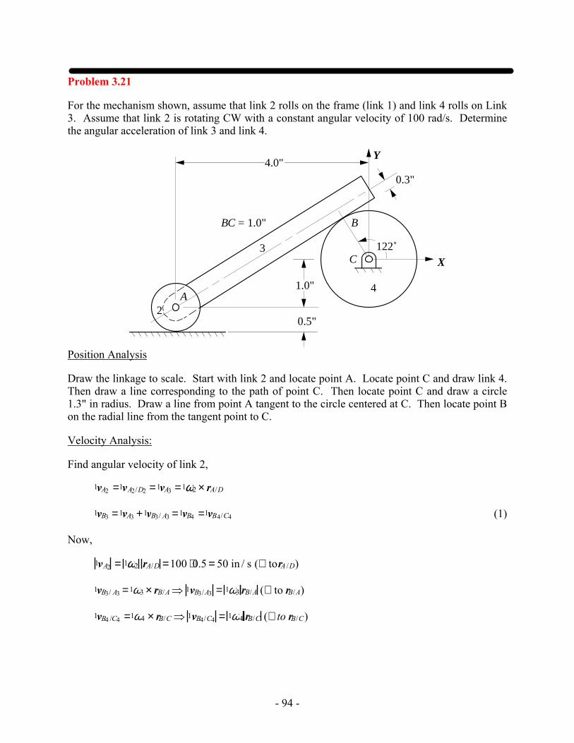
Problem 3.21
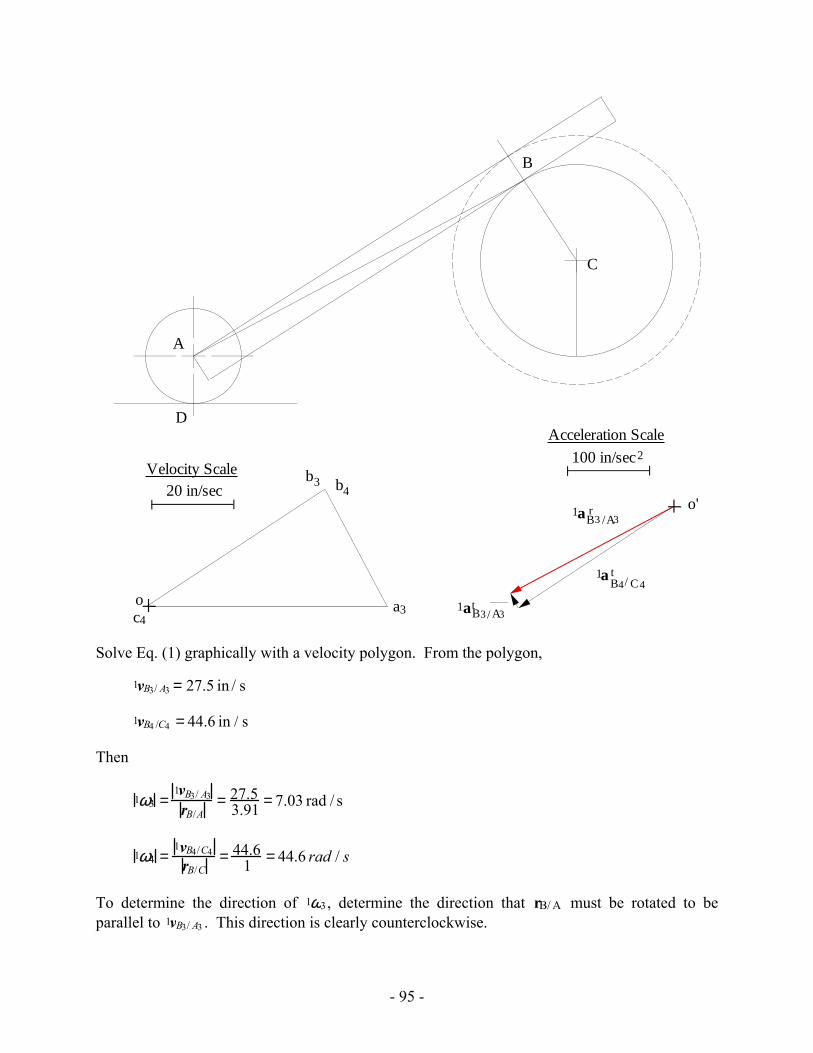
For the mechanism shown, assume that link 2 rolls on the frame (link 1) and link 4 rolls on Link 3. Assume that link 2 is rotating CW with a constant angular velocity of 100 rad/s. Determine the angular acceleration of link 3 and link 4.
C
2
3
4
B
X
Y
1.0"
122˚
0.3"
BC = 1.0"
A
0.5"
4.0"
Position Analysis
Draw the linkage to scale. Start with link 2 and locate point A. Locate point C and draw link 4. Then draw a line corresponding to the path of point C. Then locate point C and draw a circle 1.3" in radius. Draw a line from point A tangent to the circle centered at C. Then locate point B on the radial line from the tangent point to C.
Velocity Analysis:
Find angular velocity of link 2,
1vA2 =1vA2/D2 =1vA3 =1ω2 × rA/D
1vB3 =1vA3 +1vB3/ A3 =1vB4 =1vB4/C4 (1)
Now,
1vA2 = 1ω2 rA/D =100 ⋅0.5 = 50 in / s (⊥ torA /D)
1vB3/ A3 =1ω3 × rB/A⇒ 1vB3/A3 = 1ω3 rB/A (⊥ to rB/A)
1vB4 /C4 =1ω4 × rB/C ⇒ 1vB4/C4 = 1ω4 rB/C (⊥ to rB/C)
- 95 -
C
B
A
D
o'
100 in/sec
Acceleration Scale2
1aB3 /A3r
1aB3/ A3t
b3
o
20 in/secVelocity Scale
a3
b4
c4
1aB4/ C4t
Solve Eq. (1) graphically with a velocity polygon. From the polygon,
1vB3/ A3 = 27.5 in / s
1vB4 /C4 = 44.6 in / s
Then
1ω3 =1vB3/ A3
rB/A= 27.5
3.91 = 7.03 rad / s
1ω4 =1vB4/C4
rB/C= 44.6
1 = 44.6 rad / s
To determine the direction of 1ω3, determine the direction that rB/ A must be rotated to be parallel to 1vB3/ A3 . This direction is clearly counterclockwise.
- 96 -
To determine the direction of 1ω4 , determine the direction that rB/ C must be rotated to be parallel to 1vB4 /C4 . This direction is clearly clockwise.
Acceleration Analysis:
1aA3 =1aA2 =1aD2 /D1 +1aA2/D2
Because of rolling contact on a flat surface,
1aD2/D1 =1aD2 /D1n =1a D2/A2
r
Also,
1aA2/D2 = 1a A2/D2r +1aA2 /D2
t
Combining the equations,
1aA2 = 1a D2/ A2r +1a A2/ D2
r +1a A2/D2t =1aA2 /D2
t =1α2 ×rA/D = 0
Going to point B,
1aB3 =1aA3 +1aB3/A3 =1aA3 + 1a B3/A3r +1a B3/ A3
t also, 1aB3 =1aB4 +1aB3 /B4 =1aB4 /C4 +1aB3/B4 Then, 1aB4/C4 +1aB3/B4 =1aA3 + 1aB3 /A3
Expanding the terms,
1a B4 /C4r +1a B4 /C4
t + 1a B3/B4n =1aA3 +1a B3/A3
r +1a B3/A3t
Expanding 1aB3/B4n recognizing that there is rolling contact between a circle and flat surface, and
that 1aA3 = 0,
1a B4 /C4r +1a B4 /C4
t + 1aC4/ B4n = 1aB3 /A3
r +1aB3/ A3t
which simplifies to
1aB4/ C4t = 1aB3/ A3
r +1aB3 /A3t (3)
Now, 1aB3/ A3
r =1ω3 × 1ω3 × rB/A( )⇒ 1aB3/ A3r = 1ω3
2 ⋅ rB/ A = 7.042 ⋅3.91 =194 in / s2
in the direction opposite to rB/A
1aB3/ A3t =1α3 × rB/A (⊥ to rB /A)
1aB4 /C4t =1α4 × rB/C (⊥ to rB/C)
- 97 -
Solve Eq. (3) graphically with an acceleration polygon. From the polygon,
1aB3/A3t =17.2 in / s2
1aB4 /C4t =194 in / s2
Then
1α3 =1aB3/A3
t
rB/ A= 17.2
3.91 = 4.41 rad / s2
and
1α4 =1aB4/C4
t
rB /C= 194
1 = 194 rad / s2
To determine the direction of 1α3 , determine the direction that rB/A must be rotated to be parallel to 1aB3/A3
t . This direction is clearly counterclockwise.
To determine the direction of 1α4 , determine the direction that rB/C must be rotated to be parallel to 1aB4/C4
t . This direction is clearly counterclockwise.
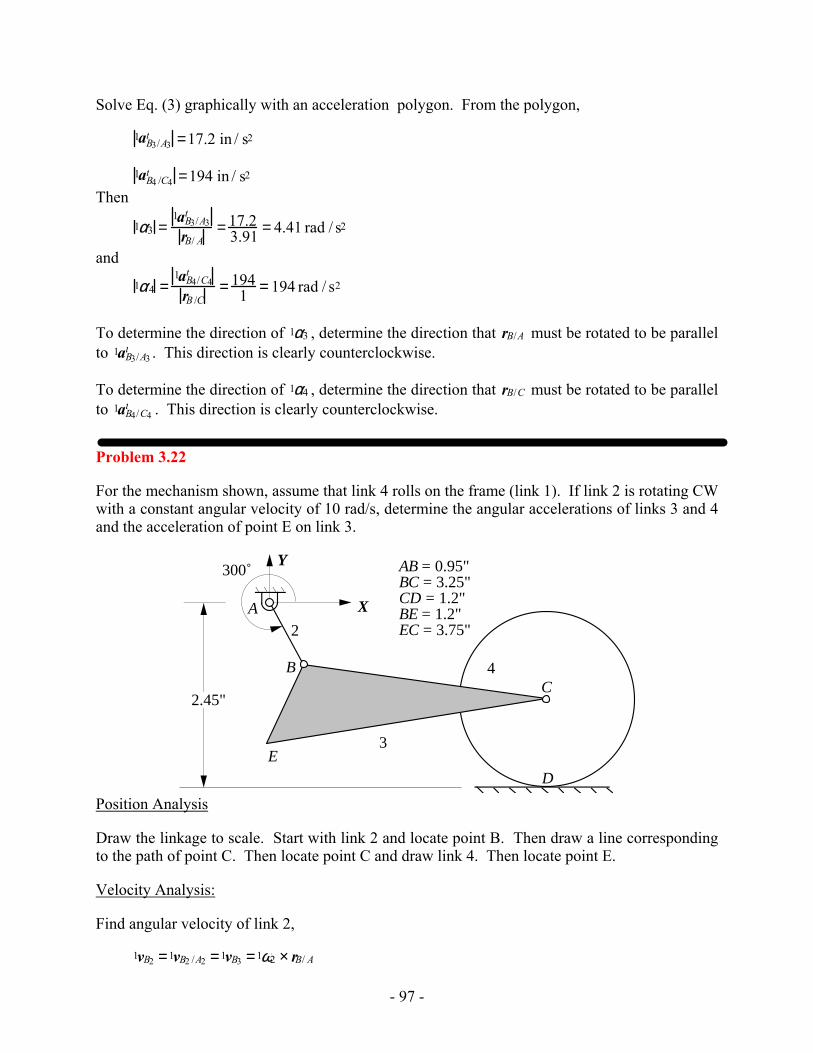
Problem 3.22
For the mechanism shown, assume that link 4 rolls on the frame (link 1). If link 2 is rotating CW with a constant angular velocity of 10 rad/s, determine the angular accelerations of links 3 and 4 and the acceleration of point E on link 3.
2
3
4
A
CB
DE
X
Y300˚
2.45"
AB = 0.95"BC = 3.25"CD = 1.2"BE = 1.2"EC = 3.75"
Position Analysis
Draw the linkage to scale. Start with link 2 and locate point B. Then draw a line corresponding to the path of point C. Then locate point C and draw link 4. Then locate point E.
Velocity Analysis:
Find angular velocity of link 2,
1vB2 =1vB2 /A2 =1vB3 =1ω2 × rB/ A
- 98 -
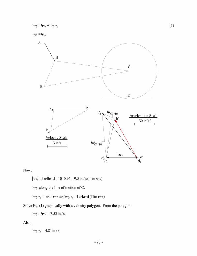
1vC3 =1vB3 +1vC3/B3 (1)
1vC3 =1vC4
b2
o
5 in/s
Velocity Scale
c3
A
D
B
C
E
o'
b'3
c'3
50 in/sAcceleration Scale
2
1aC3
1aC3 /B3r
1aC3/ B3t
c'4 d'1
e'3
Now,
1vB2 = 1ω2 rB/ A =10 ⋅0.95 = 9.5 in / s (⊥ to rB/A)
1vC3 along the line of motion of C.
1vC3 /B3 =1ω3 × rC /B ⇒ 1vC3/ B3 = 1ω3 rC/ B (⊥ to rC /B)
Solve Eq. (1) graphically with a velocity polygon. From the polygon,
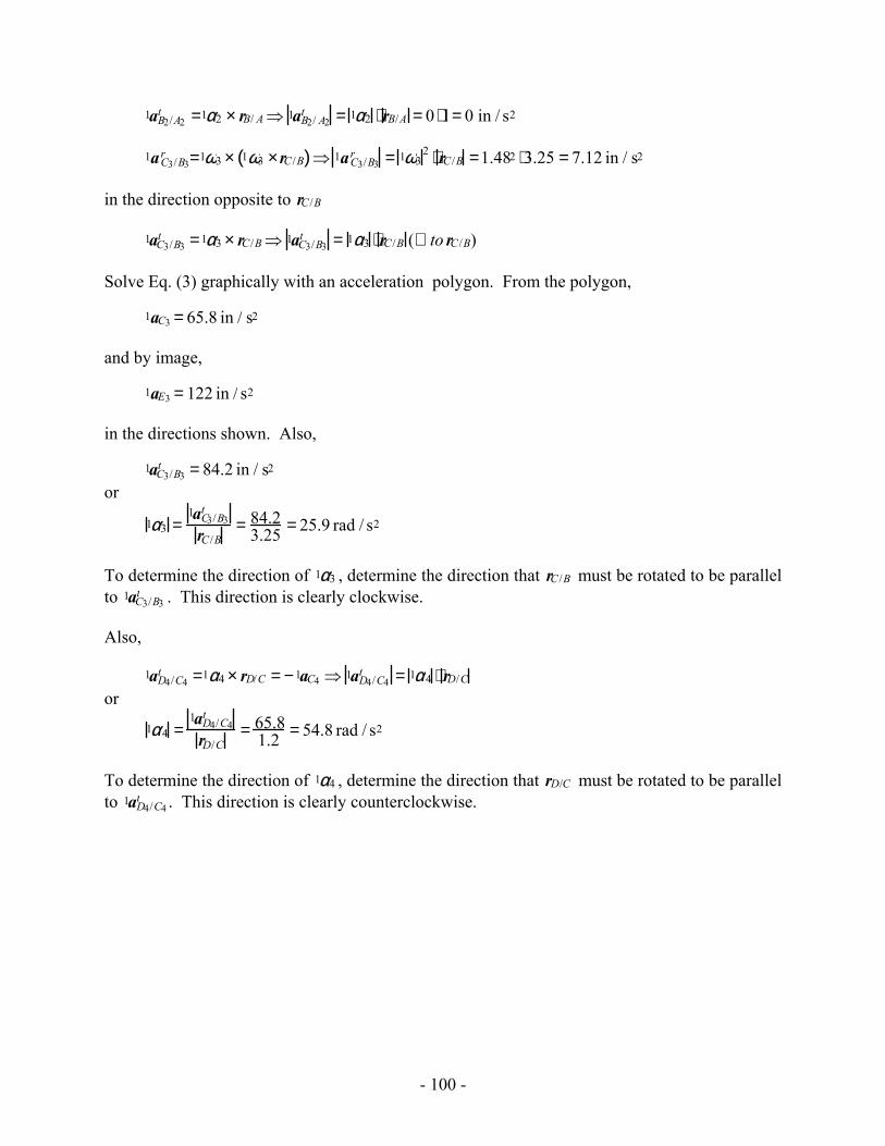
1vC3 =1vC4 = 7.53 in / s
Also,
1vC3 /B3 = 4.81in / s
- 99 -
or
1ω3 =1vC3/B3
rC /B= 4.81
3.25 =1.48 rad / s
To determine the direction of 1ω3, determine the direction that rB/A must be rotated to be parallel to 1vB3/ A3 . This direction is clearly counterclockwise.
For link 4,
1vC4 =1vD4 +1vC4/D4 =1vC4/D4 =1ω4 × rC/ D
or
1ω4 =1vC4 /D4
rC/D= 7.53
1.2 = 6.28 rad / s
To determine the direction of 1ω4 , determine the direction that rC/D must be rotated to be parallel to 1vC4/D4 . This direction is clearly counterclockwise.
Acceleration Analysis:
1aB2 =1aB3 =1a B2 /A2r +1a B2 /E2
t
1aC3 =1aC4 =1aB3 +1aC3/ B3
1aC3 =1 a B2/ A2r +1a B2/E2
t +1a C3 /B3r +1aC3/B3
t (3)
1aD4 = 1aC4 +1aD4/C4 =1aD4/ D1 =1aD4 /D1n
1aD4/D1n = 1aC4 +1a D4/C4
r +1a D4/C4t =1aD4/C4
n +1aC4/F1n +1aF1/D1
n
Where F is the center of curvature of the line. Consequently, F is at infinity and both 1aC4 /F1n and
1aF1/D1n are zero. Also, 1aD4 /C4
n and 1aD4 /C4r cancel. Therefore, the acceleration equation reduces
to
1aC4 + 1a D4/C4t =0
or 1aD4 /C4
t = −1aC4
Now,
1aC3 along the line of motion of point C.
1aB2 /A2r =1ω2 × 1ω2 × rB/ A( )⇒ 1a B2 /A2
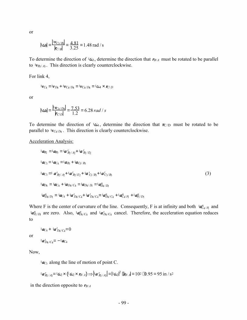
r = 1ω22 ⋅ rB/ A =102 ⋅ 0.95 = 95 in / s2
in the direction opposite to rB/A
- 100 -
1aB2/A2t =1α2 × rB/ A ⇒ 1aB2/ A2
t = 1α2 ⋅ rB/A = 0 ⋅1= 0 in / s2
1aC3/B3r =1ω3 × 1ω3 ×rC /B( )⇒ 1aC3/B3
r = 1ω32 ⋅ rC /B =1.482 ⋅3.25 = 7.12 in / s2
in the direction opposite to rC /B
1aC3/B3t =1α3 × rC /B⇒ 1aC3/B3
t = 1α3 ⋅ rC /B (⊥ to rC /B)
Solve Eq. (3) graphically with an acceleration polygon. From the polygon,
1aC3 = 65.8 in / s2
and by image,
1aE3 = 122 in / s2
in the directions shown. Also,
1aC3/B3t = 84.2 in / s2
or
1α3 =1aC3/B3
t
rC /B= 84.2
3.25 = 25.9 rad / s2
To determine the direction of 1α3 , determine the direction that rC /B must be rotated to be parallel to 1aC3/B3
t . This direction is clearly clockwise.
Also,
1aD4/C4t =1α4 × rD/C = −1aC4 ⇒ 1aD4/C4
t = 1α4 ⋅ rD/C or
1α4 =1aD4/C4
t
rD/C= 65.8
1.2 = 54.8 rad / s2
To determine the direction of 1α4 , determine the direction that rD/C must be rotated to be parallel to 1aD4/C4
t . This direction is clearly counterclockwise.

- 101 -
Problem 3.23
If vA2 = 10 in/s (constant) downward, find ω3, α3, vC3, and aC3.
A
B
2
3
Cam Contact
Rolling Contact
C
1"
45˚63˚
1.7"
E
D
FC = 1.0"FE = 2.2"FD = 0.75"DE = 2.4"
F
Velocity Analysis
1vB2 =1vA2 +1vB2/ A2 =1vA2 +1ω2 ×rB/ A
1vB3 =1vB2 +1vB3 /B2 =1vB3/F3 =1ω3 ×rB/F
Therefore,
1vB3/F3 =1vA2 +1vB2/A2 +1vB3/B2 (1)
Because of rolling contact,
1vB3/B2 = 0
Also,
1vB3/F3 =1ω3 ×rB/F (⊥ to rB/F )
1vB2 /A2 =1ω2 ×rB/A (⊥ to rB/A)
Therefore, we can solve Eq. (1) using the velocity polygon. Using the velocity polygon,
- 102 -
10 in/sVelocity Scale
D
b2, b 3
A
B
2
3
C
o
a 2
c 3
o'
a2
b'3
1aB3 / F 3t
1a B3 / F 3n
c'3, f 3
2100 in/sAcceleration ScaleF
f3
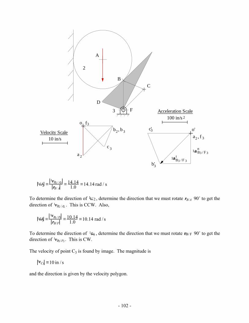
1ω2 =1vB2 /A2
rB/ A= 14.14
1.0 =14.14 rad / s
To determine the direction of 1ω2 , determine the direction that we must rotate rB/A 90˚ to get the direction of 1vB2 /A2 . This is CCW. Also,
1ω3 =1vB3 /F3
rB/F= 10.14
1.0 =10.14 rad / s
To determine the direction of 1ω3 , determine the direction that we must rotate rB/ F 90˚ to get the direction of 1vB3/F3 . This is CW.
The velocity of point C3 is found by image. The magnitude is
1vC3 =10 in / s
and the direction is given by the velocity polygon.
- 103 -
Acceleration Analysis
1aB2 =1 aA2 +1aB2/A2 =1 aA2 +1aB2/A2t +1aB2 /A2
r =1aA2 +1α2 ×rB/A+1ω2 × 1ω2 × rB/ A( )
1aB3 =1aB2 +1aB3/B2n
and
1aB3 =1aB3/F3 =1aB3/F3t +1aB3/F3
r =1α3 ×rB/F +1ω3 × 1ω3 × rB/F( )
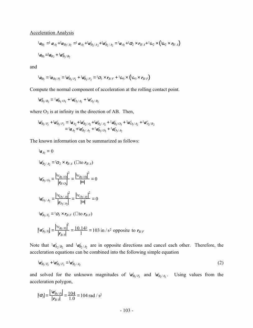
Compute the normal component of acceleration at the rolling contact point.
1aB3/B2n = 1aB3 /O3
r +1aO3/A2r +1aA2/ B2
r
where O3 is at infinity in the direction of AB. Then,
1aB3/F3
t +1aB3/F3r = 1aA2 +1aB2/A2
t +1aB2/ A2r +1aB3/O3
r +1aO3/A2r +1aA2/B2
r
=1aA2 +1aB2/ A2t +1aB3/O3
r +1aO3/A2r
The known information can be summarized as follows:
1aA2 = 0
1aB2/ A2t =1α2 × rB/A (⊥ to rB/A)
1aB3/O3r =
1vB3 /O32
rB/O3
=1vB3/O3
2
∞ = 0
1aO3/ A2r =
1vO3/ A22
rO3/A2
=1vO3/A2
2
∞ = 0
1aB3/F3t =1α3 ×rB/F (⊥ to rB/F)
1aB3/F3r =
1vB3/F32
rB/F= 10.142
1 =103 in / s2 opposite to rB/F
Note that 1aA2/B2r and 1aB2 /A2
r are in opposite directions and cancel each other. Therefore, the acceleration equations can be combined into the following simple equation
1aB3/F3t +1aB3/F3
r =1aB2 /A2t (2)
and solved for the unknown magnitudes of 1aB3/F3t and 1aB2/A2
t . Using values from the acceleration polygon,
1α3 =1aB3/F3
t
rB/F= 104
1.0 =104 rad / s2
- 104 -
To determine the direction of 1α3 , determine the direction that we must rotate rB/F 90˚ to get the direction of 1aB3/F3
t . This is CCW. The acceleration of point C3 is found by image. The magnitude is
1 aC3 =148 in / s2
and the direction is given by the polygon.
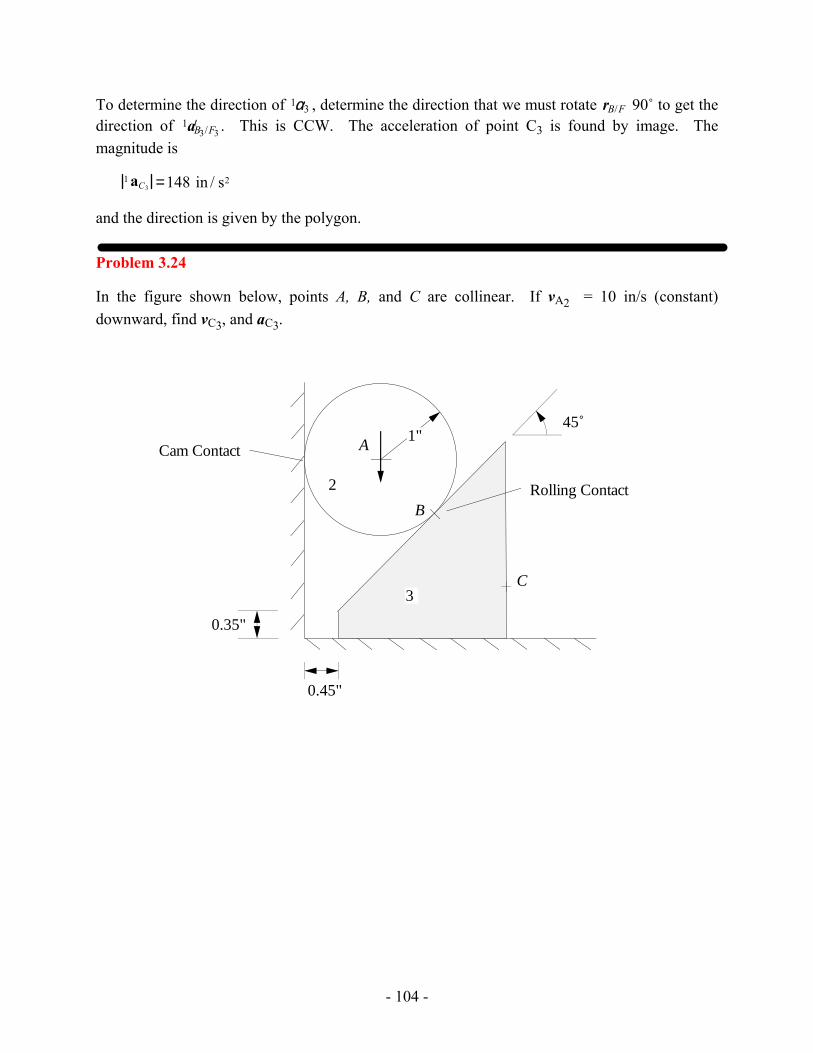
Problem 3.24
In the figure shown below, points A, B, and C are collinear. If vA2 = 10 in/s (constant) downward, find vC3, and aC3.
A
B
2
3
Cam Contact
Rolling Contact
C
1"
0.35"
45˚
0.45"
- 105 -
A
B
2
3
Cam Contact
Rolling Contact
C
a2
b2
o, c2
10 in/sec
Velocity Scale
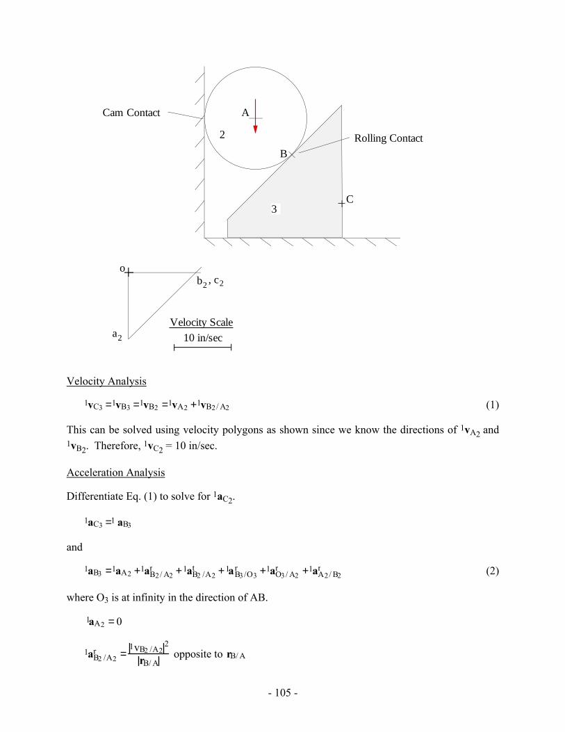
Velocity Analysis
1vC3 =1vB3 =1vB2 =1vA2 +1vB2/ A2 (1)
This can be solved using velocity polygons as shown since we know the directions of 1vA2 and 1vB2. Therefore, 1vC2 = 10 in/sec.
Acceleration Analysis
Differentiate Eq. (1) to solve for 1aC2.
1aC3 =1 aB3
and
1aB3 =1aA2 +1aB2/ A2r +1aB2 /A2
t +1aB3 /O3r +1aO3 / A2
r +1aA2/ B2r (2)
where O3 is at infinity in the direction of AB.
1aA2 = 0
1aB2 /A2r =
1vB2 /A22
rB/ A opposite to rB/ A
- 106 -
1aB2/ A2t =1α2 × rB/A (⊥ to rB/ A)
1aB3/O3r =
1vB3/O32
rB/O3=
1vB3/O32
∞ = 0
1aO3/A2r =
1vO3/A22
rO3/ A2=
1vO3/A22
∞ = 0
1aA2 /B2r =
1vA2 /B22
rA/ B
Note that 1aA2 /B2r and 1aB2 /A2
r are in opposite directions and cancel each other. Therefore, all of the terms on the right hand side of Eq. (2) are either zero or cancel each other except for 1aB2/ A2
t . Therefore,
1aB3 =1aB2/A2t
However, 1aB3 must be horizontal and 1aB2 / A2t is perpendicular to rB/ A which is not horizontal.
Because the directions are different, the magnitudes must be zero. Therefore, 1aB3 must be zero.
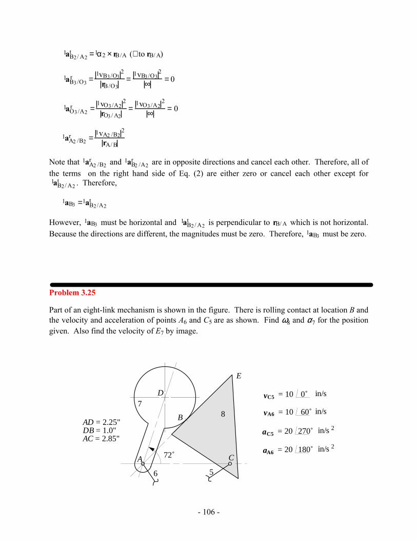
Problem 3.25
Part of an eight-link mechanism is shown in the figure. There is rolling contact at location B and the velocity and acceleration of points A6 and C5 are as shown. Find ω8 and α7 for the position given. Also find the velocity of E7 by image.
A
B
C
78
D
6 5
E
72˚
AD = 2.25"DB = 1.0"AC = 2.85"
vC5 = 10 0˚ in/s
vA6 = 10 60˚ in/s
aC5 = 20 270˚ in/s 2
aA6 = 20 180˚ in/s 2
- 107 -
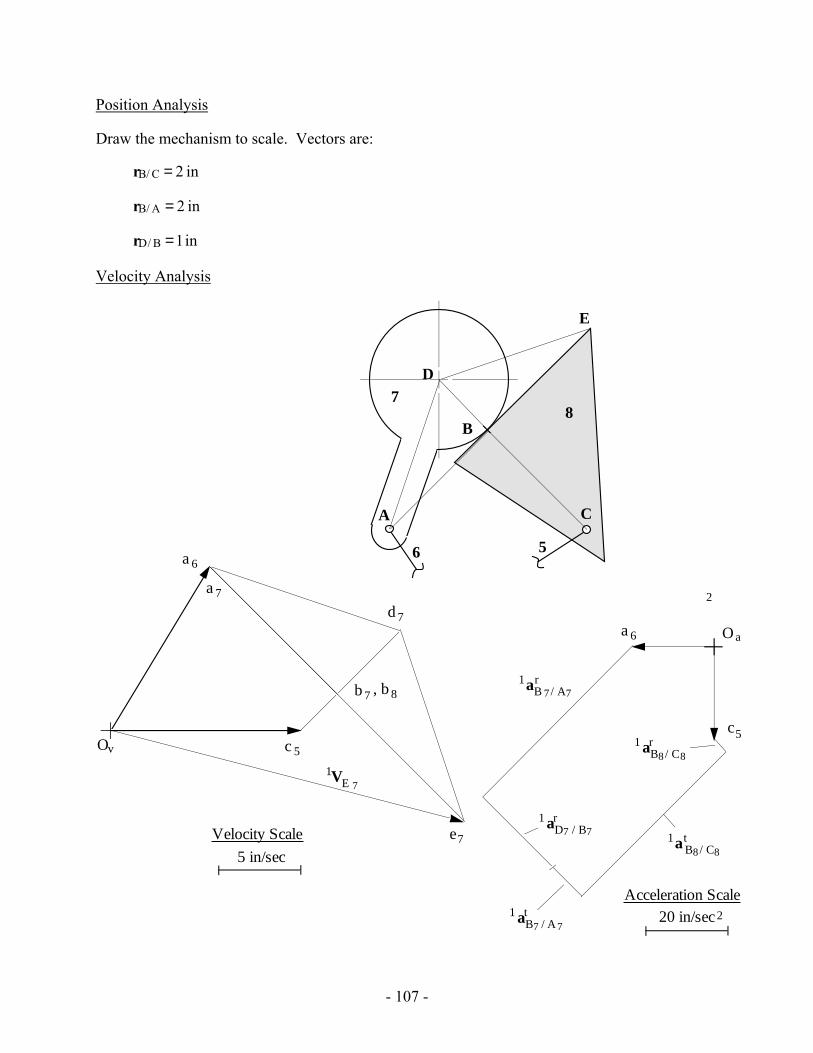
Position Analysis
Draw the mechanism to scale. Vectors are:
rB/ C = 2 in
rB/ A = 2 in
rD/ B =1in
Velocity Analysis
5 in/sec
Velocity Scale
220 in/secAcceleration Scale
O a
c5
2
Ov
6a
5c
a 6
7b 8, b
7a
7e
7d
1VE 7
A
B
C
78
D
6 5
E
1 aB8/ C8r
1a B8/ C8t
1aB 7/ A7r
1 aB7 / A7t
1 aD7 / B7r
- 108 -
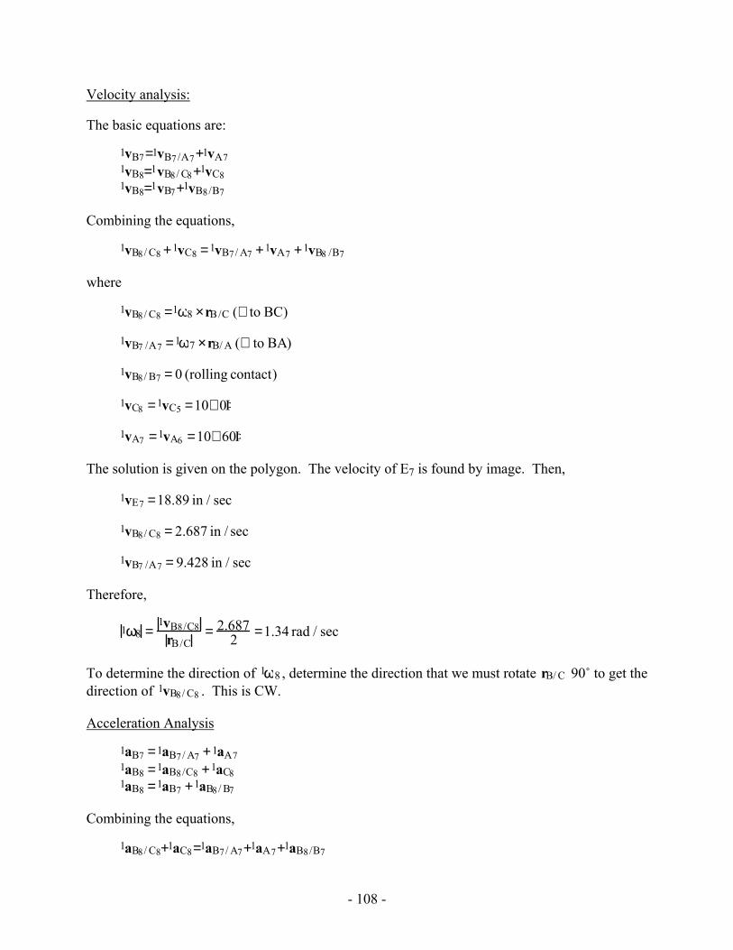
Velocity analysis:
The basic equations are:
1vB7=1vB7/A7+1vA71vB8=1vB8/ C8+1vC81vB8=1vB7+1vB8/B7
Combining the equations,
1vB8/ C8 +1vC8 =1vB7/ A7 +1vA7 +1vB8 /B7
where
1vB8/ C8 =1ω8 ×rB/C (⊥ to BC)
1vB7 /A7 =1ω7 ×rB/ A (⊥ to BA)
1vB8/ B7 = 0 (rolling contact)
1vC8 =1vC5 =10∠ 0Þ
1vA7 =1vA6 =10∠ 60Þ
The solution is given on the polygon. The velocity of E7 is found by image. Then,
1vE7 =18.89 in / sec
1vB8/ C8 = 2.687 in / sec
1vB7 /A7 = 9.428 in / sec
Therefore,
1ω8 =1vB8/C8
rB/C= 2.687
2 =1.34 rad / sec
To determine the direction of 1ω8 , determine the direction that we must rotate rB/ C 90˚ to get the direction of 1vB8/ C8 . This is CW.
Acceleration Analysis
1aB7 =1aB7/ A7 +1aA71aB8 =1aB8/C8 +1aC81aB8 =1aB7 +1aB8/ B7
Combining the equations,
1aB8/ C8+1aC8=1aB7/ A7+1aA7+1aB8/B7
- 109 -
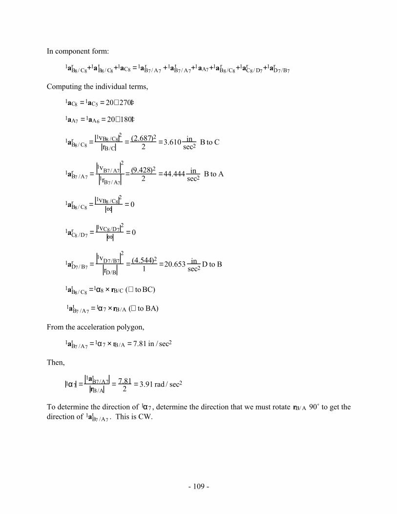
In component form:
1aB8/ C8r +1aB8/ C8
t +1aC8 =1aB7/ A7r +1aB7/ A7
t +1aA7+1aB8/C8r +1aC8/ D7
r +1aD7/B7r
Computing the individual terms,
1aC8 =1aC5 = 20∠ 270Þ
1aA7 =1aA6 = 20∠ 180Þ
1aB8/ C8r =
1vB8 /C82
rB/C= (2.687)2
2 =3.610 insec2 B to C
1aB7 /A7r =
1vB7/ A72
1rB7/ A7= (9.428)2
2 =44.444 insec2 B to A
1aB8/ C8r =
1vB8 /C82
∞ = 0
1aC8 /D7r =
1vC8/D72
∞ = 0
1aD7/ B7r =
1vD7/B72
rD/B= (4.544)2
1 =20.653 insec2 D to B
1aB8/ C8t =1α8 × rB/C (⊥ to BC)
1aB7 /A7t =1α7 ×rB/A (⊥ to BA)
From the acceleration polygon,
1aB7 /A7t =1α7 × rB/A = 7.81 in / sec2
Then,
1α7 =1aB7/A7
t
rB/A= 7.81
2 = 3.91 rad / sec2
To determine the direction of 1α7 , determine the direction that we must rotate rB/ A 90˚ to get the direction of 1aB7 /A7
t . This is CW.
- 110 -
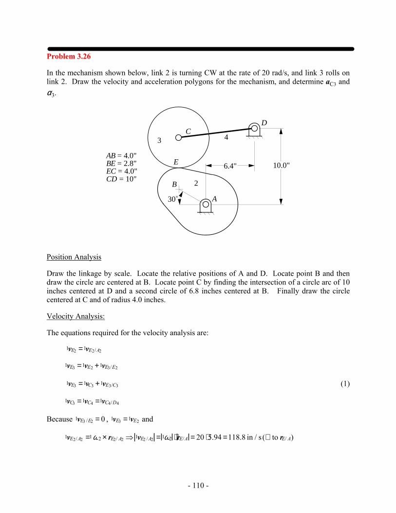
Problem 3.26
In the mechanism shown below, link 2 is turning CW at the rate of 20 rad/s, and link 3 rolls on link 2. Draw the velocity and acceleration polygons for the mechanism, and determine aC3 and α3.
AB = 4.0"BE = 2.8"EC = 4.0"CD = 10" 2
3 4
B
CD
A30˚
E 10.0"6.4"
Position Analysis
Draw the linkage by scale. Locate the relative positions of A and D. Locate point B and then draw the circle arc centered at B. Locate point C by finding the intersection of a circle arc of 10 inches centered at D and a second circle of 6.8 inches centered at B. Finally draw the circle centered at C and of radius 4.0 inches.
Velocity Analysis:
The equations required for the velocity analysis are:
1vE2 =1vE2/A2
1vE3 =1vE2 +1vE3/E2
1vE3 =1vC3 +1vE3/C3 (1)
1vC3 =1vC4 =1vC4/D4
Because 1vE3 /E2 = 0 , 1vE3 =1vE2 and
1vE2/A2 =1ω2 × rE2/ A2 ⇒ 1vE2 /A2 = 1ω2 ⋅ rE/A = 20 ⋅5.94 =118.8 in / s (⊥ to rE/ A)

- 111 -
1vE3/ C3 =1 ω3 × rE3/ C3 ⇒ 1vE3/ C3 =1ω3 ⋅ rE3 /C3 (⊥ to rE3/C3)
1vC4/ D4 =1 ω4 × rC4 /D4 ⇒ 1vC4/ D4 =1ω4 ⋅ rC4/ D4 (⊥ to rC4 /D4)
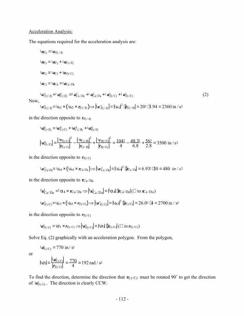
Solve Eq. (1) graphically with a velocity polygon. From the polygon,
A
B
C
2
34
E
4 in
D
e3c 3
o
100 in/s
Velocity Polygon
b2
2000 in/s
Acceleration Polygon
2
1aC4 /D4r
c3’
e2'
o'1aE3 /E2
n
1a E 2/ A2r
1a E3/ C3r
1aC4/ D4t
1a E3/ C3t
1vE3 /C3 =104 in / s or
1ω3 =1vE3/C3
rE3/C3= 104
4 = 26.0 rad / s CCW
Also, 1vC4/D4 = 69.33 in / s or
1ω4 =1vC4/D4
rC4 /D4= 69.3
10 = 6.93 rad / s CW
- 112 -
Acceleration Analysis:
The equations required for the acceleration analysis are:
1aE2 =1aE2 /A2
1aE3 =1aE2 +1aE3/E2
1aE3 =1aC3 +1aE3/C3
1aC3 =1aC4 =1aC4 /D4
1aE2/A2r +1 aE3/E2
n =1 aC4 /D4r +1 aC4/D4
t +1 aE3/C3r +1 aE3 /C3
t (2) Now, 1aE2/A2
r =1ω2 × 1ω2 × rE2/A2( )⇒ 1a E2 /A2r = 1ω2
2 ⋅ rE2 /A2 = 202 ⋅5.94 = 2360 in / s2
in the direction opposite to rE2 /A2
1aE3/E2n =1aE3/C3
n +1aC3/B2n +1aB2/E2
n
1aE3/E2n =
1vE3 /C32
rE3/C3−
1vC3/B22
rC3/ B2+
1vB2/E22
rB2/E2= 1042
4 − 48.32
6.8 + 562
2.8 = 3500 in / s2
in the direction opposite to rE3/C3
1aC4/D4r =1ω4 × 1ω4 × rC4/D4( )⇒ 1aC4 /D4
r = 1ω42 ⋅ rC4 /D4 = 6.932 ⋅10 = 480 in / s2
in the direction opposite to rC4/ D4
1aC4/ D4t =1 α4 × rC4/ D4 ⇒ 1aC4 /D4
t = 1α4 ⋅ rC4/ D4 (⊥ to rC4 /D4)
1aE3/C3r =1ω3 × 1ω3 × rE3/C3( )⇒ 1a E3/C3
r = 1ω32 ⋅ rE3/C3 = 26.02 ⋅4 = 2700 in / s2
in the direction opposite to rE3/C3
1aE3/C3t =1α3 ×rE3/C3 ⇒ 1aE3/C3
t = 1α3 ⋅ rE3/C3 (⊥ to rE3/C3)
Solve Eq. (2) graphically with an acceleration polygon. From the polygon,
1aE3/C3t = 770 in / s2
or
1α3 =1aE3/C3
t
rE3/C3= 770
4 =192 rad / s2
To find the direction, determine the direction that rE3/C3 must be rotated 90˚ to get the direction of 1aE3/C3
t . The direction is clearly CCW.
- 113 -
Also from the polygon,
1aC3 = 1290 in / s2
Problem 3.27
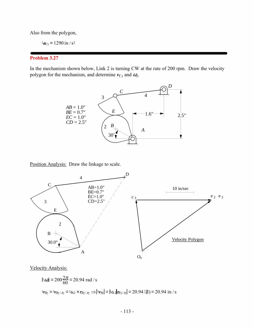
In the mechanism shown below, Link 2 is turning CW at the rate of 200 rpm. Draw the velocity polygon for the mechanism, and determine vC3 and ω3.
2
3 4
B
CD
A30˚
AB = 1.0"BE = 0.7"EC = 1.0"CD = 2.5"
E 1.6" 2.5"
Position Analysis: Draw the linkage to scale.
30.0°
A
B
C
D
2
3
4
AB=1.0"BE=0.7"EC=1.0"CD=2.5"
10 in/sec
Velocity Polygon
Ov
e 2 e 3
E
c 3
Velocity Analysis:
1ω2 = 200 2π60 = 20.94 rad / s
1vB2 =1vB2 /A2 =1ω2 ×rB2/ A2 ⇒ 1vB2 = 1ω2 rB2/A2 = 20.94 ⋅(1) = 20.94 in / s
- 114 -
1vE2 =1vE2/ A2 =1ω2 × rE2/ A2 ⇒ 1vE2 = 1ω2 rE2/ A2 = 20.94 ⋅(1.46) = 30.57 in / s
1vE3 =1vE2
1vC3 =1vE3 +1vC3/E3 (1)
Now,
1vE3 = 30.57 in / s (⊥ to rE/A)
1vC3 =1vC4 =1ω4 × rC /D (⊥ to rC /D)
1vE3 /C3 =1ω3 × rE/C (⊥ to rE /C) tangent to two circles.
Solve Eq. (1) graphically with a velocity polygon. The velocity directions can be gotten directly from the polygon. The magnitudes are given by:
1vE3/C3 = 27 in / s⇒ 1ω3 =1vE3/C3
rE /C= 27
1 = 27 rad / s
From the directions given in the position and velocity polygons
1ω3 = 27rad / s CCW
Also, from the velocity polygon,
1vC3 =18.29 in / s
- 115 -
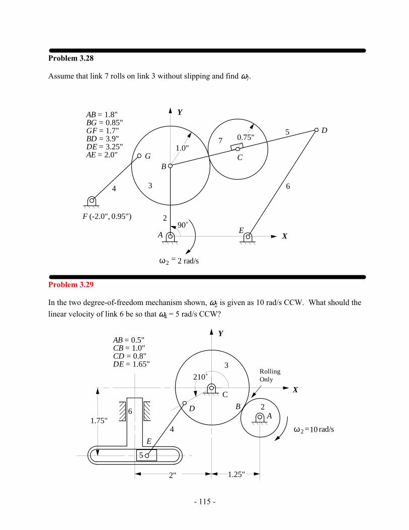
Problem 3.28
Assume that link 7 rolls on link 3 without slipping and find ω7.
ω2 = 2 rad/s
2
34
5
6
7
X
Y
A
BC
D
E
G
F (-2.0", 0.95")
AB = 1.8"BG = 0.85"GF = 1.7"BD = 3.9"DE = 3.25"AE = 2.0"
1.0"0.75"
90˚
Problem 3.29
In the two degree-of-freedom mechanism shown, ω2 is given as 10 rad/s CCW. What should the linear velocity of link 6 be so that ω4 = 5 rad/s CCW?
2
4
5
6B
C
D
E
3
ω2 =10 rad/s
RollingOnly
X
Y
2"
1.75"
AB = 0.5"CB = 1.0"CD = 0.8"DE = 1.65"
210˚
1.25"
A
- 116 -
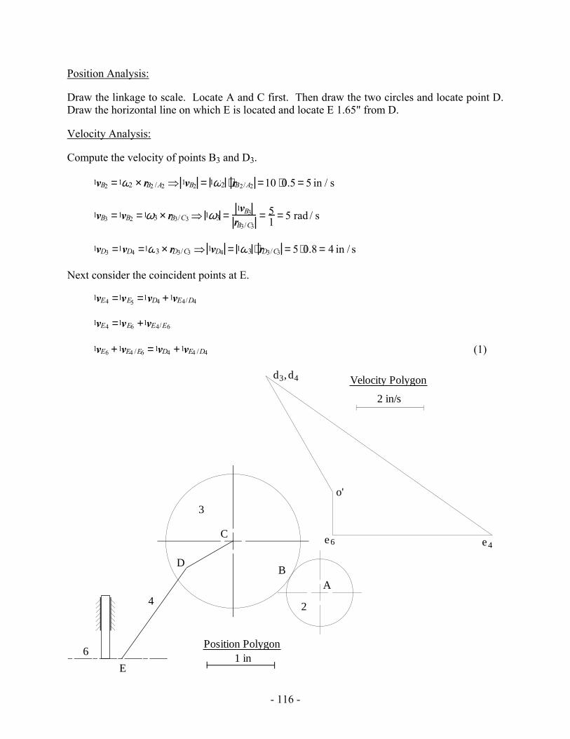
Position Analysis:
Draw the linkage to scale. Locate A and C first. Then draw the two circles and locate point D. Draw the horizontal line on which E is located and locate E 1.65" from D.
Velocity Analysis:
Compute the velocity of points B3 and D3.
1vB2 =1ω2 × rB2 /A2 ⇒ 1vB2 = 1ω2 ⋅ rB2/A2 =10 ⋅0.5 = 5 in / s
1vB3 =1vB2 =1ω3 × rB3/C3 ⇒ 1ω3 =1vB3
rB3/C3= 5
1 = 5 rad / s
1vD3 =1vD4 =1ω3 × rD3/C3 ⇒ 1vD4 = 1ω3 ⋅ rD3/C3 = 5 ⋅0.8 = 4 in / s
Next consider the coincident points at E.
1vE4 =1vE5 =1vD4 +1vE4/D4
1vE4 =1vE6 +1vE4/E6
1vE6 +1vE4 /E6 =1vD4 +1vE4 /D4 (1)
o'
2 in/s
Velocity Polygond3 d4,
e6 e4
4
BD
2
3
6
A
C
E1 in
Position Polygon
- 117 -
Now,
1vD4 = 4 in / s (⊥ to rD3/C3)
1vE4/ D4 = 1ω4 ⋅ rE4 /D4 = 5 ⋅1.65 = 8.25 in / s (⊥ to rE4/D4 )
1vE6 is in the vertical direction,
1vE4/ E6 is in the horizontal direction.
Solve Eq. (1) graphically with a velocity polygon. From the polygon
1vE6 =1.28 in / s in the direction shown on the polygon.
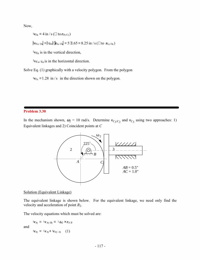
Problem 3.30
In the mechanism shown, ω2 = 10 rad/s. Determine vC3/C2 and vC3 using two approaches: 1) Equivalent linkages and 2) Coincident points at C
ω2
2 3
A
B
C
225˚
AB = 0.5"AC = 1.0"
Solution (Equivalent Linkage)
The equivalent linkage is shown below. For the equivalent linkage, we need only find the velocity and acceleration of point B2.
The velocity equations which must be solved are:
1vA2 = 1vA2/B2 = 1ω2 ×rA/B and 1vA2 = 1vA3+ 1vA2 /A3 (1)
- 118 -
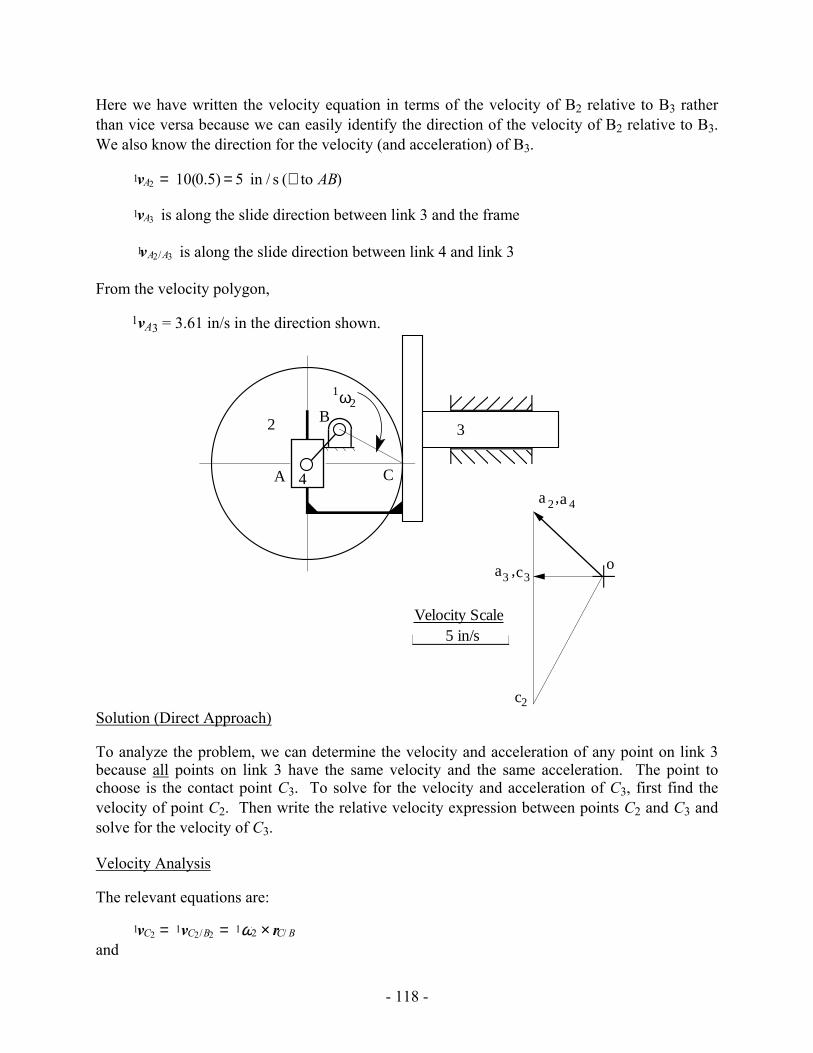
Here we have written the velocity equation in terms of the velocity of B2 relative to B3 rather than vice versa because we can easily identify the direction of the velocity of B2 relative to B3. We also know the direction for the velocity (and acceleration) of B3.
1vA2 = 10(0.5) = 5 in / s (⊥ to AB)
1vA3 is along the slide direction between link 3 and the frame
1vA2/A3 is along the slide direction between link 4 and link 3
From the velocity polygon,
1vA3 = 3.61 in/s in the direction shown.
1ω2
2 3
A
B
C4
o
a 2 a 4,
c2
a3 c3,
5 in/sVelocity Scale
Solution (Direct Approach)
To analyze the problem, we can determine the velocity and acceleration of any point on link 3 because all points on link 3 have the same velocity and the same acceleration. The point to choose is the contact point C3. To solve for the velocity and acceleration of C3, first find the velocity of point C2. Then write the relative velocity expression between points C2 and C3 and solve for the velocity of C3.
Velocity Analysis
The relevant equations are:
1vC2 = 1vC2/B2 = 1ω2 × rC/ B and
- 119 -
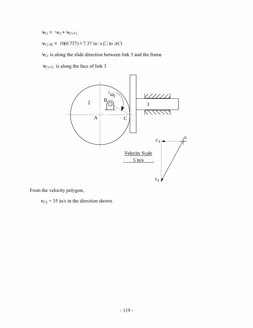
1vC3 = 1vC2 + 1vC3/C2
1vC2/B2 = 10(0.737) = 7.37 in / s (⊥ to AC)
1vC3 is along the slide direction between link 3 and the frame
1vC3/C2 is along the face of link 3
1ω2
2 3
A
B
C
o
c2
c3
5 in/sVelocity Scale
From the velocity polygon,
vC3 = 35 in/s in the direction shown.
- 120 -
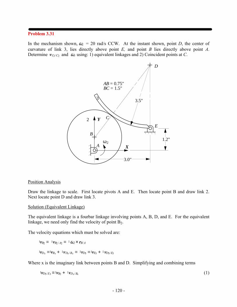
Problem 3.31
In the mechanism shown, ω2 = 20 rad/s CCW. At the instant shown, point D, the center of curvature of link 3, lies directly above point E, and point B lies directly above point A. Determine vC3/C2 and ω3 using: 1) equivalent linkages and 2) Coincident points at C.
2
A
D
3
B
C
ω2X
Y
AB = 0.75"BC = 1.5"
3.5"
3.0"
E
1.2"
Position Analysis
Draw the linkage to scale. First locate pivots A and E. Then locate point B and draw link 2. Next locate point D and draw link 3.
Solution (Equivalent Linkage)
The equivalent linkage is a fourbar linkage involving points A, B, D, and E. For the equivalent linkage, we need only find the velocity of point B2.
The velocity equations which must be solved are:
1vB2 = 1vB2 /A2 = 1ω2 × rB/A
1vDx =1vBx + 1vDx /Bx = 1vD3 =1vE3 + 1vD3/E3
Where x is the imaginary link between points B and D. Simplifying and combining terms
1vD3/E3 =1vB2 + 1vDx /Bx (1)
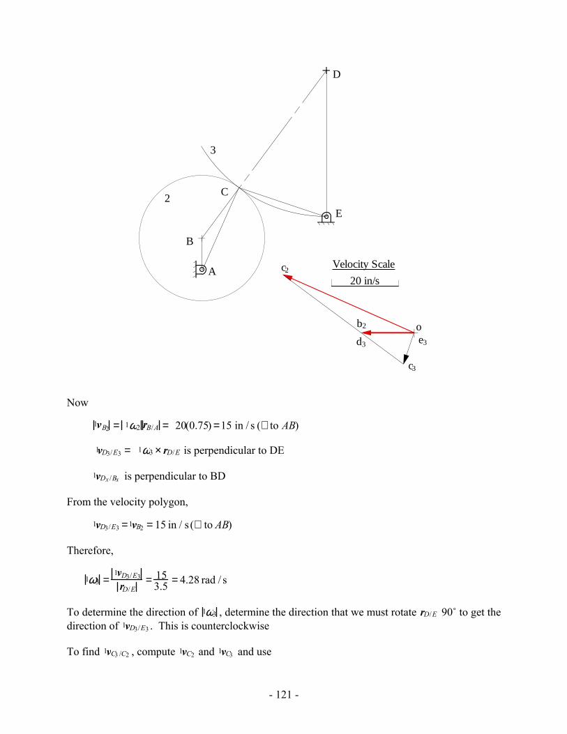
- 121 -
b2
2
A
3
B
C
D
E
d3 e3
20 in/s
Velocity Scale
o
c2
c3
Now
1vB2 = 1ω2 rB/A = 20(0.75) =15 in / s (⊥ to AB)
1vD3/E3 = 1ω3 × rD/E is perpendicular to DE
1vDx /Bx is perpendicular to BD
From the velocity polygon,
1vD3/E3 =1vB2 = 15 in / s (⊥ to AB)
Therefore,
1ω3 =1vD3/E3
rD/E= 15
3.5 = 4.28 rad / s
To determine the direction of 1ω3 , determine the direction that we must rotate rD/E 90˚ to get the direction of 1vD3/E3 . This is counterclockwise
To find 1vC3 /C2 , compute 1vC2 and 1vC3 and use
- 122 -
1vC3 /C2 =1vC3 −1vC2
Both 1vC2 and 1vC3 may be determined by velocity image (or computed directly). From the polygon,
1vC3 /C2 = 44.8 in / s
in the direction indicated by the polygon.
Solution (Direct Approach)
First find the velocity of point C2. Then write the relative velocity expression between points C2 and C3 and solve for the velocity of C3.
The relevant equations are:
1vC2 = 1vC2/ A2 = 1ω2 × rC /A and 1vC3 = 1vC2 + 1vC3/C2 = 1vC3/E3
Where
1vC2/A2 = 20(2.158) = 43.16 in / s (⊥ to AC)
1vC3/E3 is perpendicular to CE
1vC3/C2 is along the tangent to the contact point (perpendicular to BD)
From the velocity polygon,
1vC3 /C2 = 44.8 in / s and 1vC3/E3 = 9.84 in / s
Therefore,
1ω3 = 1vC3/E3
rC /E= 9.84
2.30 = 4.28 rad / s
To determine the direction of 1ω3 , determine the direction that we must rotate rC /E 90˚ to get the direction of 1vC3/E3 . This is counterclockwise
- 123 -
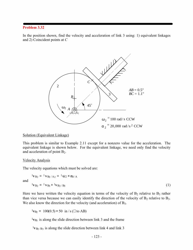
Problem 3.32
In the position shown, find the velocity and acceleration of link 3 using: 1) equivalent linkages and 2) Coincident points at C
ω2 A
B
C2
3
ω2= 100 rad/ s CCW
α 2= 20,000 rad /s 2 CCW
45˚
AB = 0.5"BC = 1.1"
Solution (Equivalent Linkage)
This problem is similar to Example 2.11 except for a nonzero value for the acceleration. The equivalent linkage is shown below. For the equivalent linkage, we need only find the velocity and acceleration of point B2.
Velocity Analysis
The velocity equations which must be solved are:
1vB2 = 1 vB2 / A2 = 1 ω2 × rB/ A and 1vB2 = 1 vB3 + 1vB2 / B3 (1)
Here we have written the velocity equation in terms of the velocity of B2 relative to B3 rather than vice versa because we can easily identify the direction of the velocity of B2 relative to B3. We also know the direction for the velocity (and acceleration) of B3.
1vB2 = 100(0.5) = 50 in / s (⊥ to AB)
1vB3 is along the slide direction between link 3 and the frame
1vB2 /B3 is along the slide direction between link 4 and link 3
- 124 -
B
C
2
A
50 in/sec
b3
b2o
aB2/B33
aB 3
b'3
o'
5,000 in/sec
2
3
4
b'2
aB2/A2r
Acceleration Scale
Velocity Scale
From the velocity polygon,
vB3 = 35 in/s in the direction shown.
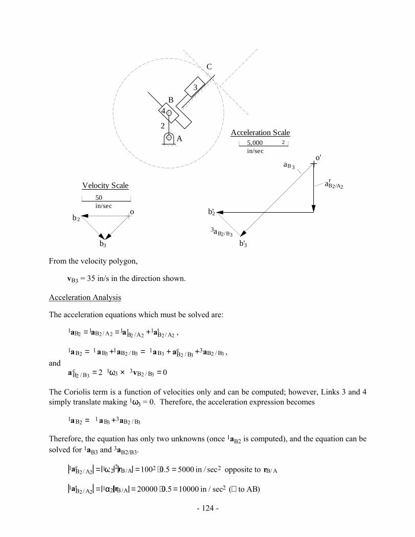
Acceleration Analysis
The acceleration equations which must be solved are:
1aB2 =1aB2/ A2 =1aB2 /A2r +1aB2/ A2
t ,
1aB2 = 1 aB3 +1aB2 / B3 = 1aB3 + aB2 / B3c +3aB2 / B3 ,
and aB2 / B3
c = 2 1ω3 × 3vB2 / B3 = 0
The Coriolis term is a function of velocities only and can be computed; however, Links 3 and 4 simply translate making 1ω3 = 0. Therefore, the acceleration expression becomes
1aB2 = 1 aB3 +3aB2 / B3
Therefore, the equation has only two unknowns (once 1aB2 is computed), and the equation can be solved for 1aB3 and 3aB2/B3.
1aB2/ A2r = 1ω2
2rB/A =1002 ⋅0.5 = 5000 in / sec2 opposite to rB/ A
1aB2/ A2t = 1α2 rB/A = 20000 ⋅0.5 =10000 in / sec2 (⊥ to AB)
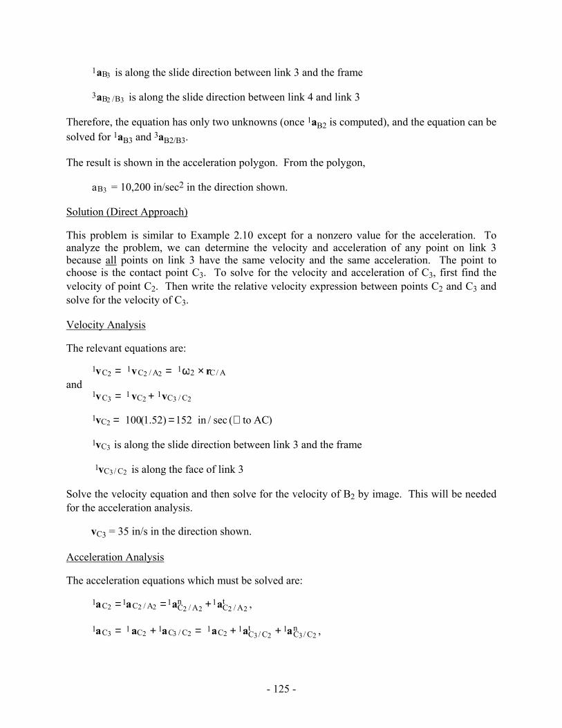
- 125 -
1aB3 is along the slide direction between link 3 and the frame
3aB2 /B3 is along the slide direction between link 4 and link 3
Therefore, the equation has only two unknowns (once 1aB2 is computed), and the equation can be solved for 1aB3 and 3aB2/B3.
The result is shown in the acceleration polygon. From the polygon,
aB3 = 10,200 in/sec2 in the direction shown.
Solution (Direct Approach)
This problem is similar to Example 2.10 except for a nonzero value for the acceleration. To analyze the problem, we can determine the velocity and acceleration of any point on link 3 because all points on link 3 have the same velocity and the same acceleration. The point to choose is the contact point C3. To solve for the velocity and acceleration of C3, first find the velocity of point C2. Then write the relative velocity expression between points C2 and C3 and solve for the velocity of C3.
Velocity Analysis
The relevant equations are:
1vC2 = 1vC2 / A2 = 1ω2 × rC/ A and 1vC3 = 1 vC2 + 1vC3 / C2
1vC2 = 100(1.52) =152 in / sec (⊥ to AC)
1vC3 is along the slide direction between link 3 and the frame
1vC3/ C2 is along the face of link 3
Solve the velocity equation and then solve for the velocity of B2 by image. This will be needed for the acceleration analysis.
vC3 = 35 in/s in the direction shown.
Acceleration Analysis
The acceleration equations which must be solved are:
1aC2 =1aC2 / A2 =1aC2 / A2n +1aC2 / A2
t ,
1aC3 = 1 aC2 + 1aC3 / C2 = 1aC2 + 1aC3/ C2t + 1aC3/ C2
n ,
- 126 -
ω 1 2
B
C
2
3
A
1 inch
50 in/sec
c2
c3
b2o
Velocity Scale
c2
aC2/A2r
aC3 /C2n
aC3/C2t
aC3c3
o'
10,000 in/sec 2
Acceleration ScaleaC2/A2
t
and
1aC3/ C2n = 1aC3/ D3
n + 1aD3 / B2n + 1aB2 / C2
n =1vC3 / D3
2
∞ +1vD3 / B2
2
∞ +1vB2 / C2
2
rB/C=
1vB2 / C22
rB/ C
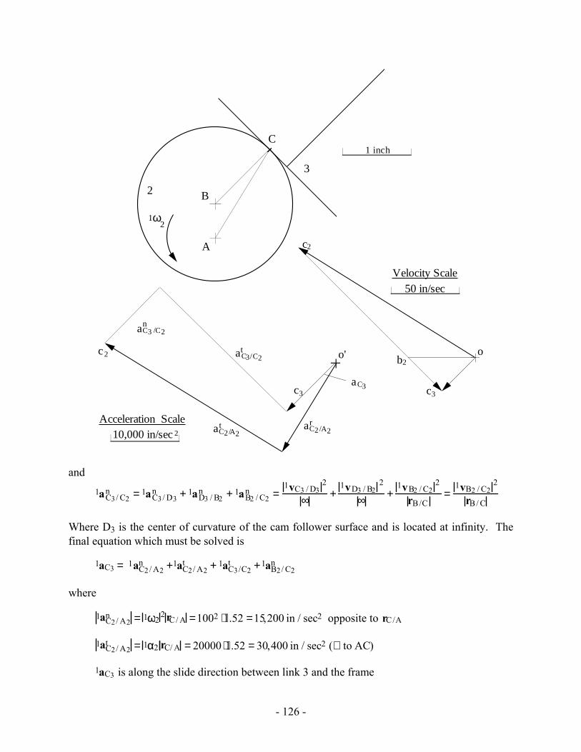
Where D3 is the center of curvature of the cam follower surface and is located at infinity. The final equation which must be solved is
1aC3 = 1aC2/ A2n +1aC2/ A2
t + 1aC3/C2t +1aB2/ C2
n
where
1aC2/ A2n = 1ω2
2 rC/ A =1002 ⋅1.52 =15,200 in / sec2 opposite to rC/A
1aC2/ A2t = 1α2 rC/ A = 20000 ⋅1.52 = 30,400 in / sec2 (⊥ to AC)
1aC3 is along the slide direction between link 3 and the frame
- 127 -
1aB2/ C2n =
1vB2/C22
rB/C= 112.92
1.11 =11,480 in / s2 from B to C
1aC3/C2t is along the along the face of link 3
Therefore, the equation has only two unknowns (once 1aC2 is computed), and the equation can be solved for 1aC3 and 1aC3/C2
t .
The result is shown in the acceleration polygon. From the polygon,
aC3 = 10,200 in/sec2 in the direction shown.
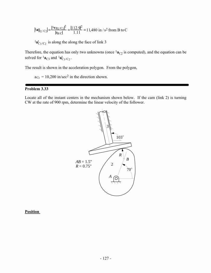
Problem 3.33
Locate all of the instant centers in the mechanism shown below. If the cam (link 2) is turning CW at the rate of 900 rpm, determine the linear velocity of the follower.
A
B2
3
70˚
R
AB = 1.5"R = 0.75"
103˚
Position
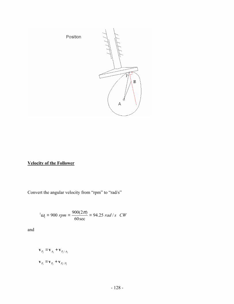
- 128 -
Velocity of the Follower
Convert the angular velocity from “rpm” to “rad/s”
12
900(2 )900 94.25 /60sec
rpm rad s CWπω = = =
and
2 2 2 2/P A P A= +v v v
3 2 3 2/P P P P= +v v v
- 129 -
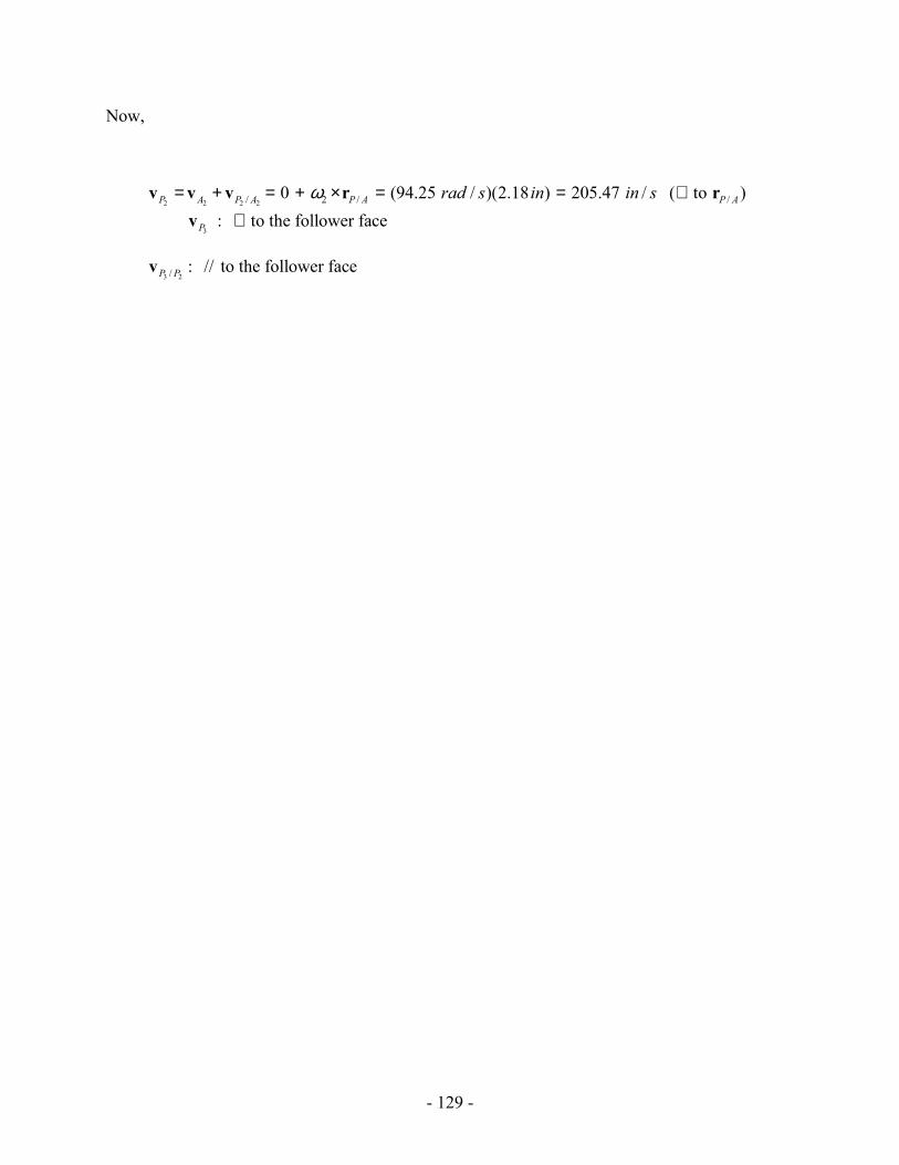
Now,
2 2 2 2/ 2 / /0 (94.25 / )(2.18 ) 205.47 / ( to )P A P A P A P Arad s in in sω= + = + × = = ⊥v v v r r
3: to the follower faceP ⊥v
3 2/ : // to the follower faceP Pv
- 130 -
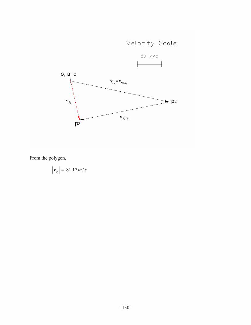
From the polygon,
381.17 /P in s=v
- 131 -
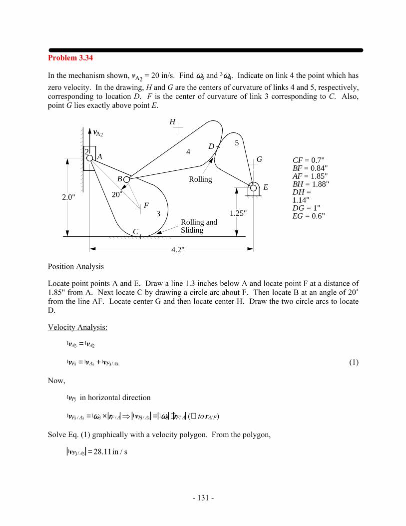
Problem 3.34
In the mechanism shown, vA2 = 20 in/s. Find ω5 and 3ω4. Indicate on link 4 the point which has zero velocity. In the drawing, H and G are the centers of curvature of links 4 and 5, respectively, corresponding to location D. F is the center of curvature of link 3 corresponding to C. Also, point G lies exactly above point E.
CF = 0.7"BF = 0.84"AF = 1.85"BH = 1.88"DH = 1.14"DG = 1"EG = 0.6"
2A
Rolling
3
45
C
B
D
Rolling and Sliding
vA2
F2.0" 20˚
4.2"
G
H
1.25"
E
Position Analysis
Locate point points A and E. Draw a line 1.3 inches below A and locate point F at a distance of 1.85" from A. Next locate C by drawing a circle arc about F. Then locate B at an angle of 20˚ from the line AF. Locate center G and then locate center H. Draw the two circle arcs to locate D.
Velocity Analysis:
1vA3 =1vA2
1vF3 =1vA3 +1vF3/A3 (1)
Now,
1vF3 in horizontal direction
1vF3 /A3 =1ω3 × rF /A ⇒ 1vF3/A3 = 1ω3 ⋅ rF/ A (⊥ to rA/F)
Solve Eq. (1) graphically with a velocity polygon. From the polygon,
1vF3/A3 = 28.11in / s
- 132 -
b3
10 in/sec
Velocity Polygon
A
B
C
D
E
F
G
H
a3
f3
b3
o
d4 d5
e5
b4
3
4
5
o4
O4
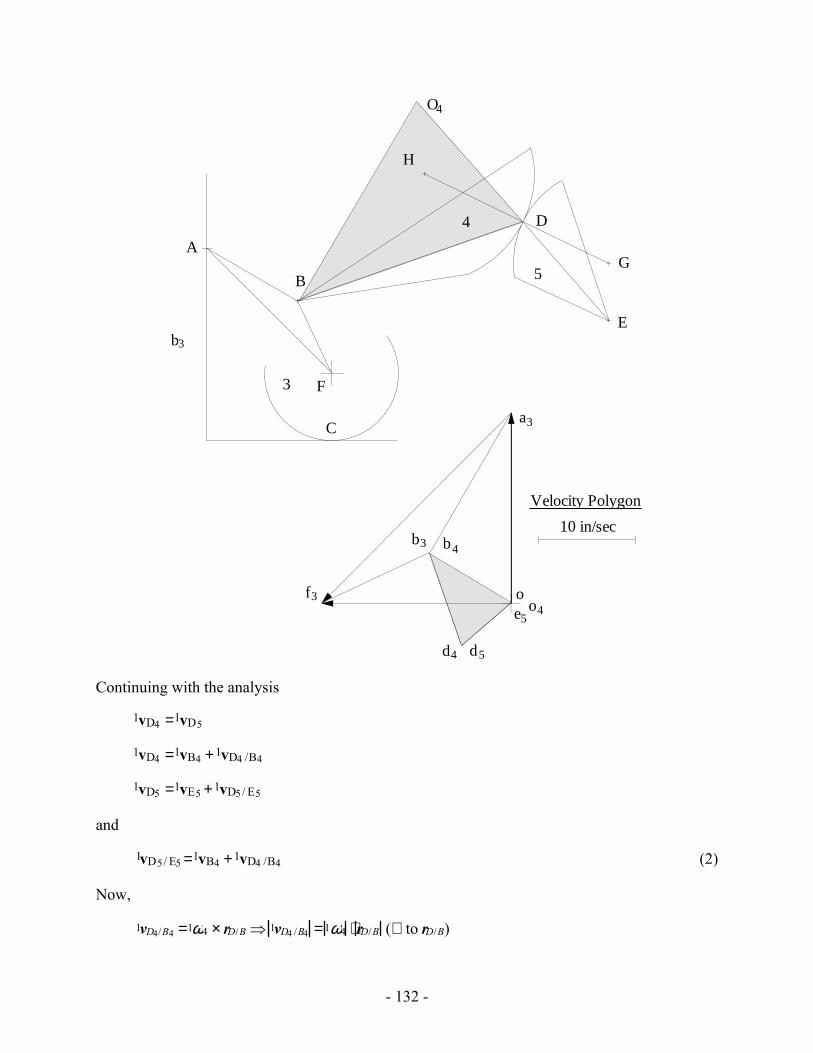
Continuing with the analysis
1vD4 =1vD5
1vD4 =1vB4 +1vD4 /B4
1vD5 =1vE5 +1vD5/ E5
and
1vD5/ E5 =1vB4 +1vD4 /B4 (2)
Now,
1vD4/B4 =1ω4 × rD/B ⇒ 1vD4 /B4 =1ω4 ⋅ rD/B (⊥ to rD/B)
- 133 -
1vD5/E5 =1ω5 × rD/E ⇒ 1vD5/E5 =1ω5 ⋅ rD/E (⊥ to rD/E)
Solve Eq. (2) graphically with a velocity polygon. From the polygon,
1vD4/B4 =10.30 in / s
1vD5 /E5 = 6.91 in / s
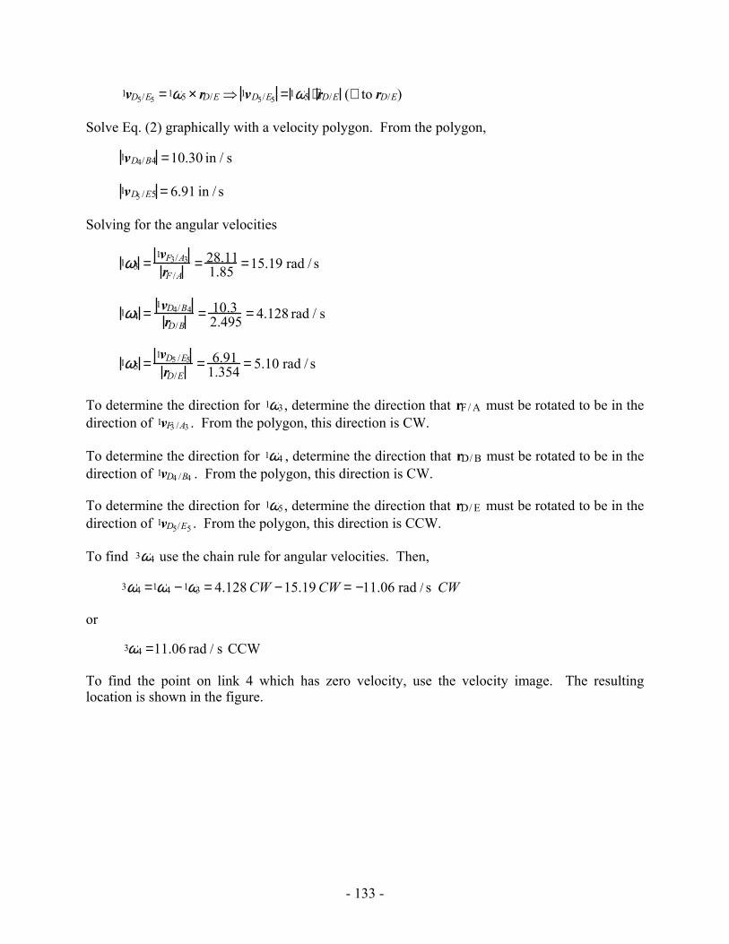
Solving for the angular velocities
1ω3 =1vF3/A3
rF /A= 28.11
1.85 =15.19 rad / s
1ω4 =1vD4/B4
rD/B= 10.3
2.495 = 4.128 rad / s
1ω5 =1vD5 /E5
rD/E= 6.91
1.354 = 5.10 rad / s
To determine the direction for 1ω3, determine the direction that rF/ A must be rotated to be in the direction of 1vF3 /A3 . From the polygon, this direction is CW.
To determine the direction for 1ω4 , determine the direction that rD/ B must be rotated to be in the direction of 1vD4 /B4 . From the polygon, this direction is CW.
To determine the direction for 1ω5, determine the direction that rD/ E must be rotated to be in the direction of 1vD5/E5 . From the polygon, this direction is CCW.
To find 3ω4 use the chain rule for angular velocities. Then,
3ω4 =1ω4 −1ω3 = 4.128 CW −15.19 CW = −11.06 rad / s CW
or
3ω4 =11.06 rad / s CCW
To find the point on link 4 which has zero velocity, use the velocity image. The resulting location is shown in the figure.
- 134 -
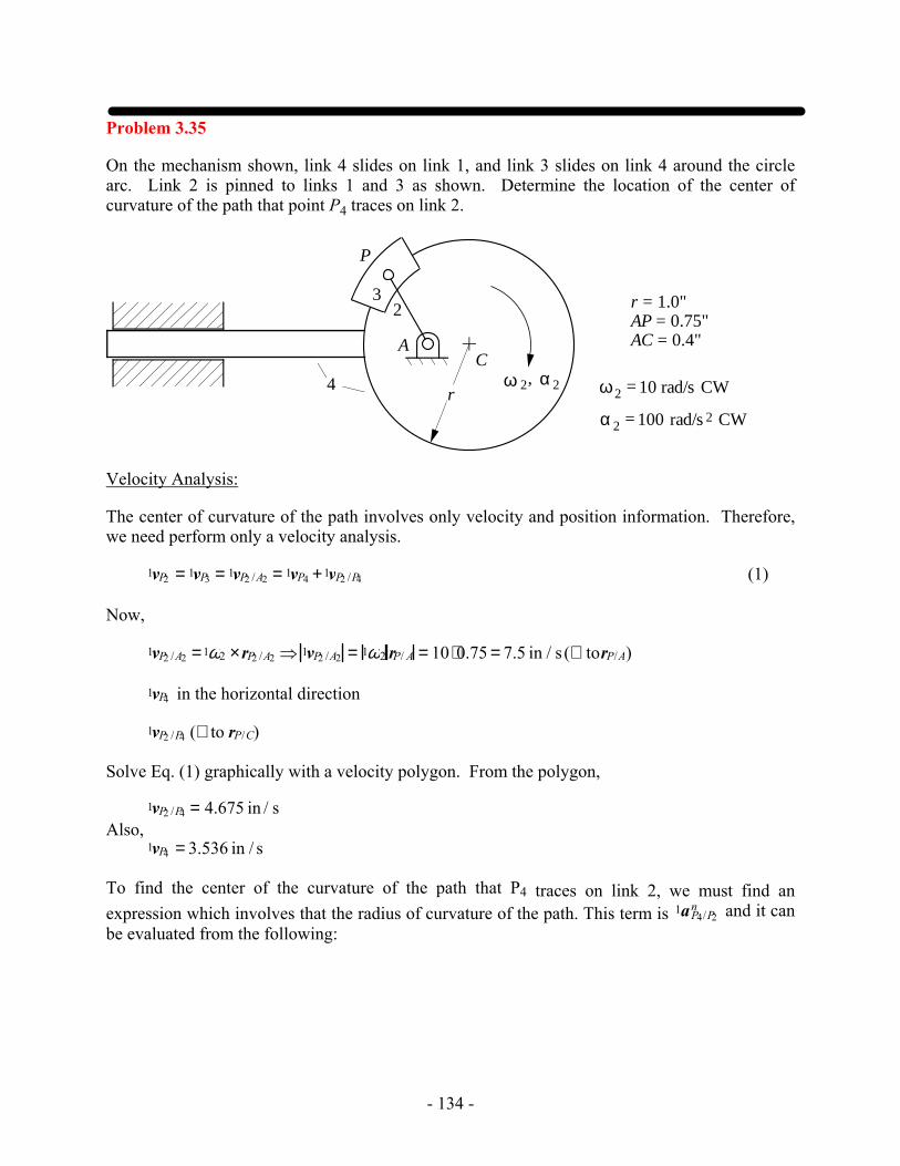
Problem 3.35
On the mechanism shown, link 4 slides on link 1, and link 3 slides on link 4 around the circle arc. Link 2 is pinned to links 1 and 3 as shown. Determine the location of the center of curvature of the path that point P4 traces on link 2.
4
P
AC
23
α 2ω 2,
ω2 = 10 rad/s CW
α 2 = 100 rad/s 2 CW
r
r = 1.0"AP = 0.75"AC = 0.4"
Velocity Analysis:
The center of curvature of the path involves only velocity and position information. Therefore, we need perform only a velocity analysis.
1vP2 = 1vP3 = 1vP2 /A2 = 1vP4 +1vP2 /P4 (1)
Now,
1vP2 /A2 =1ω2 ×rP2 /A2 ⇒ 1vP2 /A2 = 1ω2 rP/ A = 10⋅0.75 = 7.5 in / s (⊥ torP/A)
1vP4 in the horizontal direction
1vP2 /P4 (⊥ to rP/C)
Solve Eq. (1) graphically with a velocity polygon. From the polygon,
1vP2 /P4 = 4.675 in / s Also, 1vP4 = 3.536 in / s
To find the center of the curvature of the path that P4 traces on link 2, we must find an expression which involves that the radius of curvature of the path. This term is 1aP4/P2
n and it can be evaluated from the following:
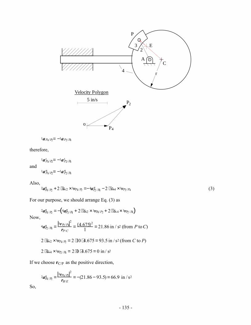
- 135 -
4
P
AC
23
r
o
5 in/s
Velocity Polygon
P4
P2
E
1aP4/P2= −1aP2/P4
therefore,
1aP4/P2t = −1aP2/P4
t and 1aP4/P2
n = −1aP2/P4n
Also, 2aP4 /P2
n +2 ⋅1ω2 ×1vP4/P2 =−4aP2 /P4n −2 ⋅1ω4 ×1vP2/P4 (3)
For our purpose, we should arrange Eq. (3) as
2aP4 /P2n = − 4aP2/P4
n + 2 ⋅1ω2 ×1vP4/P2 + 2 ⋅1ω4 ×1vP2 /P4( ) Now,
4aP2 /P4n =
1vP2/P42
rP/C= 4.675( )2
1 = 21.86 in / s2 (from P to C)
2 ⋅1ω2 ×1vP4/P2 = 2 ⋅10 ⋅ 4.675 = 93.5 in / s2 (from C to P)
2 ⋅1ω4 ×1vP2 /P4 = 2 ⋅0 ⋅4.675 = 0 in / s2
If we choose rC/P as the positive direction,
2aP4 /P2n =
1vP4/P22
rB/E= −(21.86 − 93.5) = 66.9 in / s2
So,
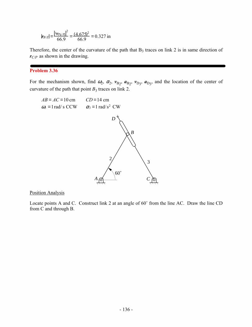
- 136 -
rB/E =1vP4/P2
2
66.9 = 4.675( )2
66.9 = 0.327 in
Therefore, the center of the curvature of the path that B3 traces on link 2 is in same direction of rC/P as shown in the drawing.
Problem 3.36
For the mechanism shown, find ω2, α2, vB2, aB2, vD3, aD3, and the location of the center of curvature of the path that point B3 traces on link 2.
AB = AC =10 cm CD =14 cmω3 =1rad/ s CCW α3 =1 rad/ s2 CW
CA
D
23
60˚
B
Position Analysis
Locate points A and C. Construct link 2 at an angle of 60˚ from the line AC. Draw the line CD from C and through B.
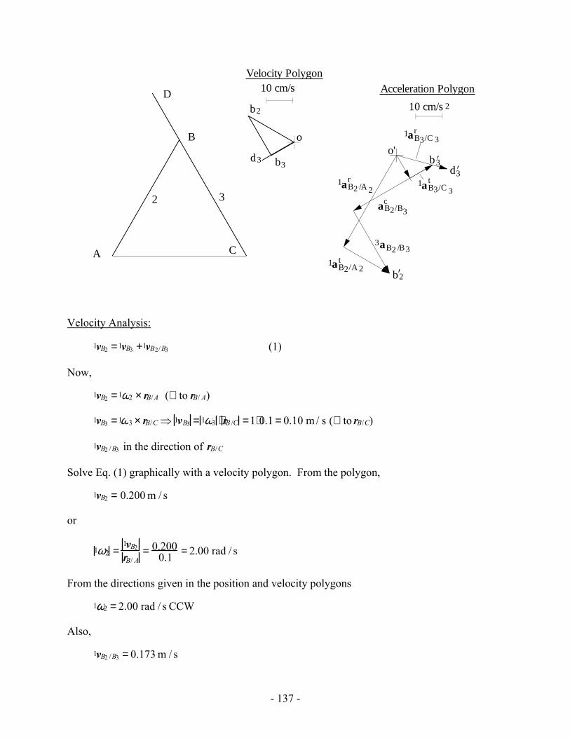
- 137 -
C
B
A
2 3
o
10 cm/sVelocity Polygon
b3
b2
o'
1aB2/A 2t
b3’
b2’
10 cm/s
Acceleration Polygon
2
3aB2 /B3
caB2/B3
1aB3/C 3t
1aB3/C 3r
1aB2 /A 2r
D
d3d3’
Velocity Analysis:
1vB2 =1vB3 +1vB2/B3 (1)
Now,
1vB2 =1ω2 × rB/A (⊥ to rB/ A)
1vB3 =1ω3 × rB/C ⇒ 1vB3 = 1ω3 ⋅ rB /C =1⋅0.1 = 0.10 m / s (⊥ to rB/C)
1vB2 /B3 in the direction of rB/C
Solve Eq. (1) graphically with a velocity polygon. From the polygon,
1vB2 = 0.200 m / s
or
1ω2 =1vB2
rB/ A= 0.200
0.1 = 2.00 rad / s
From the directions given in the position and velocity polygons
1ω2 = 2.00 rad / s CCW
Also,
1vB2 /B3 = 0.173 m / s
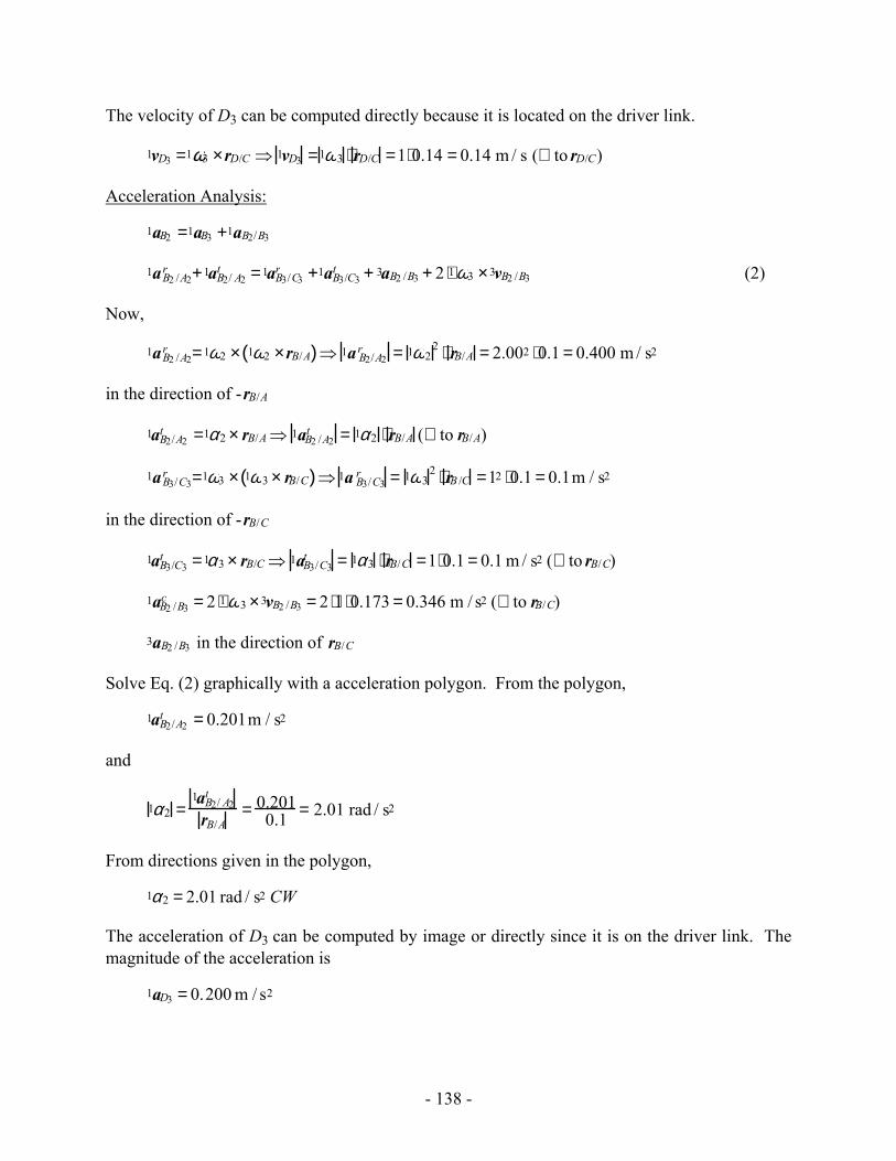
- 138 -
The velocity of D3 can be computed directly because it is located on the driver link.
1vD3 =1ω3 ×rD/C ⇒ 1vD3 =1ω3 ⋅ rD/C =1⋅0.14 = 0.14 m / s (⊥ to rD/C)
Acceleration Analysis:
1aB2 =1aB3 +1aB2/B3
1aB2 /A2r +1aB2/ A2
t =1aB3/C3r +1aB3/C3
t + 3aB2 /B3 + 2 ⋅1ω3 ×3vB2 /B3 (2)
Now,
1aB2 /A2r =1ω2 × 1ω2 ×rB/A( )⇒ 1a B2/A2
r = 1ω22 ⋅ rB/A = 2.002 ⋅0.1 = 0.400 m / s2
in the direction of -rB/A
1aB2/A2t =1α2 × rB/A ⇒ 1aB2 /A2
t = 1α2 ⋅ rB/A (⊥ to rB/A)
1aB3/C3r =1ω3 × 1ω3 × rB/C( )⇒ 1a B3/C3
r = 1ω32 ⋅ rB /C =12 ⋅0.1 = 0.1m / s2
in the direction of -rB/C
1aB3/C3t =1α3 × rB/C ⇒ 1aB3/C3
t = 1α3 ⋅ rB/C =1⋅0.1 = 0.1 m / s2 (⊥ to rB/C)
1aB2 /B3c = 2 ⋅1ω3 ×3vB2 /B3 = 2 ⋅1 ⋅0.173 = 0.346 m / s2 (⊥ to rB/C)
3aB2 /B3 in the direction of rB/C
Solve Eq. (2) graphically with a acceleration polygon. From the polygon,
1aB2/A2t = 0.201m / s2
and
1α2 =1aB2/ A2
t
rB/A= 0.201
0.1 = 2.01 rad / s2
From directions given in the polygon,
1α2 = 2.01 rad / s2 CW
The acceleration of D3 can be computed by image or directly since it is on the driver link. The magnitude of the acceleration is
1aD3 = 0.200 m / s2
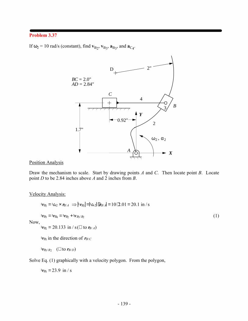
- 139 -
Problem 3.37
If ω2 = 10 rad/s (constant), find vB2, vB3, aB3, and aC4.
α2ω2 ,
2
3
4
A
C
B
D 2"
1.7"
X
Y
BC = 2.0"AD = 2.84"
0.92"
Position Analysis
Draw the mechanism to scale. Start by drawing points A and C. Then locate point B. Locate point D to be 2.84 inches above A and 2 inches from B.
Velocity Analysis:
1vB2 =1ω2 × rB/A ⇒ 1vB2 =1ω2 ⋅ rB/A =10 ⋅2.01 = 20.1 in / s
1vB3 =1vB4 =1vB2 +1vB3/B2 (1) Now, 1vB2 = 20.133 in / s (⊥ to rB/ A)
1vB3 in the direction of rB/C
1vB3/B2 (⊥ to rB/D)
Solve Eq. (1) graphically with a velocity polygon. From the polygon,
1vB3 = 23.9 in / s
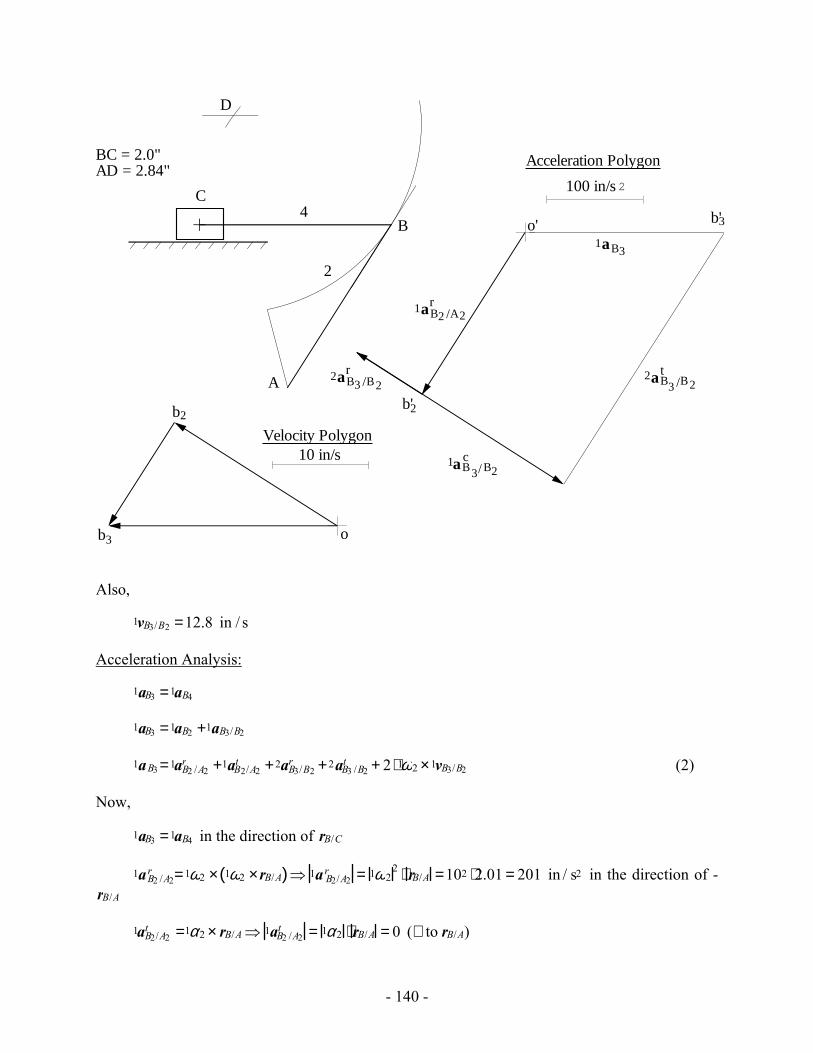
- 140 -
A
o'
100 in/s
Acceleration Polygon
2
b'2
1aB3/ B2c
1aB3
o
10 in/sVelocity Polygon
b2
b3
2
4C
B
D
BC = 2.0"AD = 2.84"
1aB2 /A2r
2aB3 /B2r 2aB3 /B2
t
b'3
Also,
1vB3/B2 =12.8 in / s
Acceleration Analysis:
1aB3 =1aB4
1aB3 =1aB2 +1aB3/B2
1aB3 =1aB2 /A2r +1aB2/A2
t +2aB3/B2r +2aB3 /B2
t + 2 ⋅1ω2 ×1vB3/B2 (2)
Now,
1aB3 =1aB4 in the direction of rB/C
1aB2 /A2r =1ω2 × 1ω2 ×rB/A( )⇒ 1a B2/A2
r = 1ω22 ⋅ rB/A =102 ⋅2.01 = 201 in / s2 in the direction of -
rB/A
1aB2/A2t =1α2 × rB/A⇒ 1aB2 /A2
t = 1α2 ⋅ rB/A = 0 (⊥ to rB/A)
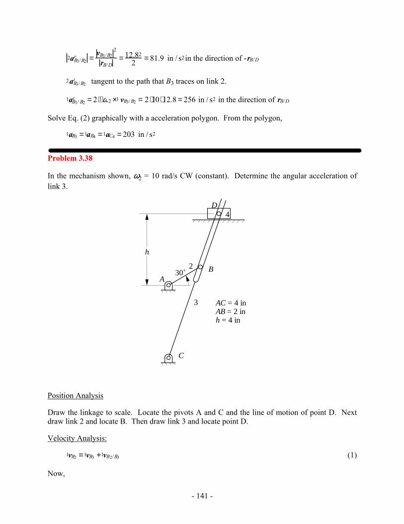
- 141 -
2aB3/B2r =
vB3/B22
rB/D= 12.82
2 = 81.9 in / s2in the direction of -rB/D
2aB3/B2t tangent to the path that B3 traces on link 2.
1aB3/ B2c = 2 ⋅1ω2 ×1 vB3/B2 = 2 ⋅10 ⋅12.8 = 256 in / s2 in the direction of rB/D
Solve Eq. (2) graphically with a acceleration polygon. From the polygon,
1aB3 =1aB4 =1aC4 = 203 in / s2
Problem 3.38
In the mechanism shown, ω2 = 10 rad/s CW (constant). Determine the angular acceleration of link 3.
2
3
4
A
C
B
D
h
30˚
AC = 4 inAB = 2 inh = 4 in
Position Analysis
Draw the linkage to scale. Locate the pivots A and C and the line of motion of point D. Next draw link 2 and locate B. Then draw link 3 and locate point D.
Velocity Analysis:
1vB2 =1vB3 +1vB2/B3 (1)
Now,
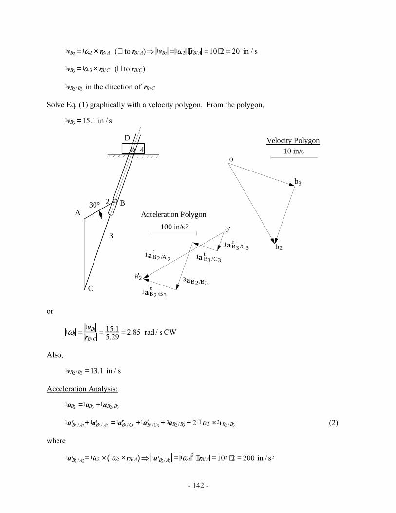
- 142 -
1vB2 =1ω2 × rB/A (⊥ to rB/ A)⇒ 1vB2 =1ω2 ⋅ rB/A =10 ⋅2 = 20 in / s
1vB3 =1ω3 × rB/C (⊥ to rB/C)
1vB2 /B3 in the direction of rB/C
Solve Eq. (1) graphically with a velocity polygon. From the polygon,
1vB3 =15.1 in / s
2
3
4
A
C
B
D
30°
o'
a'2
1aB2 /A 2r
100 in/s
Acceleration Polygon
2
b2
10 in/sVelocity Polygon
o
b3
1aB2 /B3c
3aB2 /B3
1a B3 /C3t
1aB3 /C3r
or
1ω3 =1vB3
rB/C= 15.1
5.29 = 2.85 rad / s CW
Also,
1vB2 /B3 =13.1 in / s
Acceleration Analysis:
1aB2 =1aB3 +1aB2/B3
1aB2 /A2r +1aB2/ A2
t =1aB3/C3r +1aB3/C3
t + 3aB2 /B3 + 2 ⋅1ω3 ×3vB2 /B3 (2)
where
1aB2 /A2r =1ω2 × 1ω2 ×rB/A( )⇒ 1a B2/A2
r = 1ω22 ⋅ rB/A =102 ⋅2 = 200 in / s2
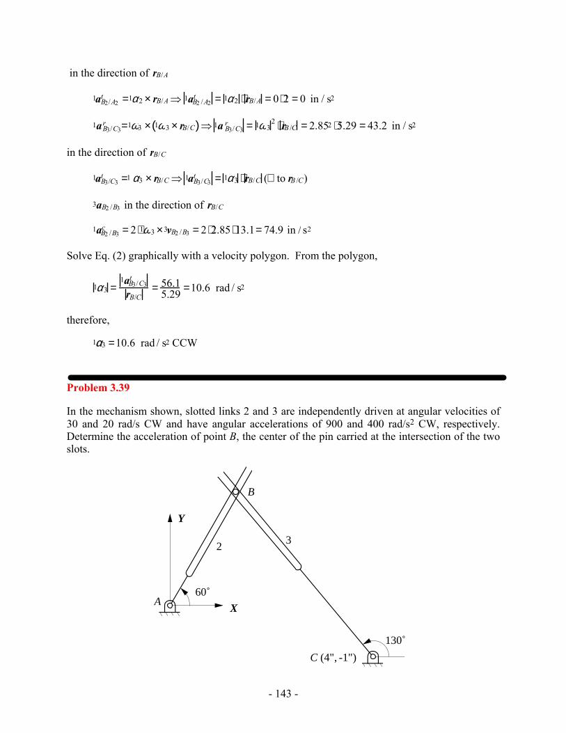
- 143 -
in the direction of rB/A
1aB2/A2t =1α2 × rB/A⇒ 1aB2 /A2
t = 1α2 ⋅ rB/A = 0 ⋅2 = 0 in / s2
1aB3/C3r =1ω3 × 1ω3 × rB/C( )⇒ 1a B3/C3
r = 1ω32 ⋅ rB /C = 2.852 ⋅5.29 = 43.2 in / s2
in the direction of rB/C
1aB3/C3t =1 α3 × rB/C ⇒ 1aB3/C3
t = 1α3 ⋅ rB/C (⊥ to rB /C)
3aB2 /B3 in the direction of rB/C
1aB2 /B3c = 2 ⋅1ω3 ×3vB2 /B3 = 2 ⋅2.85 ⋅13.1= 74.9 in / s2
Solve Eq. (2) graphically with a velocity polygon. From the polygon,
1α3 =1aB3/C3
t
rB/C= 56.1
5.29 =10.6 rad / s2
therefore,
1α3 =10.6 rad / s2 CCW
Problem 3.39
In the mechanism shown, slotted links 2 and 3 are independently driven at angular velocities of 30 and 20 rad/s CW and have angular accelerations of 900 and 400 rad/s2 CW, respectively. Determine the acceleration of point B, the center of the pin carried at the intersection of the two slots.
23
A
B
X
Y
60˚
130˚
C (4", -1")
- 144 -
Position Analysis
Locate the pivots A and C. Then draw links 2 and 3 in the orientations shown.
rB/A = 2.58 in
rB/C = 4.23 in
Velocity Analysis
Consider the points at location B.
1vB2 =1vB2 /A2 =1ω2 ×rB/A ⇒ 1vB2 /A2 = 1ω2 ⋅ rB/A = 30(2.58) = 77.4 in / s (⊥ to rB/A)
1vB3 =1vB3/C3 =1ω3 × rB/C ⇒ 1vB3/C3 = 1ω2 ⋅ rB/C = 20(4.23) = 84.6 in / s (⊥ to rB/C )
Call the pin link 4. Then,
1vB4 =1vB3 +1vB4/B3 = 1vB2 +1vB4/B2 (1)
Where,
1vB4/ B2 is along rB/A
1vB4 /B3 is along rB/C
Solve Eq. (1) using the velocity polygon. Then,
1vB4/ B2 =118 in/s
1vB4 /B3 =113 in/s
Acceleration Analysis
Consider the points at location B.
1aB2 =1aB2/A2 =1aB2 /A2r +1 aB2/ A2
t
1aB3 =1aB3/C3 =1aB3/C3r +1 aB3/C3
t
Call the pin link 4. Then,
1aB4 =1aB3 +1aB4/ B3 = 1aB2 +1aB4 /B2
or
1aB3/C3r +1 aB3/C3
t +3aB4/B3t +3aB4/B3
r +aB4 /B3c =1aB2/A2
r +1aB2 /A2t +3aB4/B2
t +3aB4/B2r +aB4/ B2
c (2)
Where,
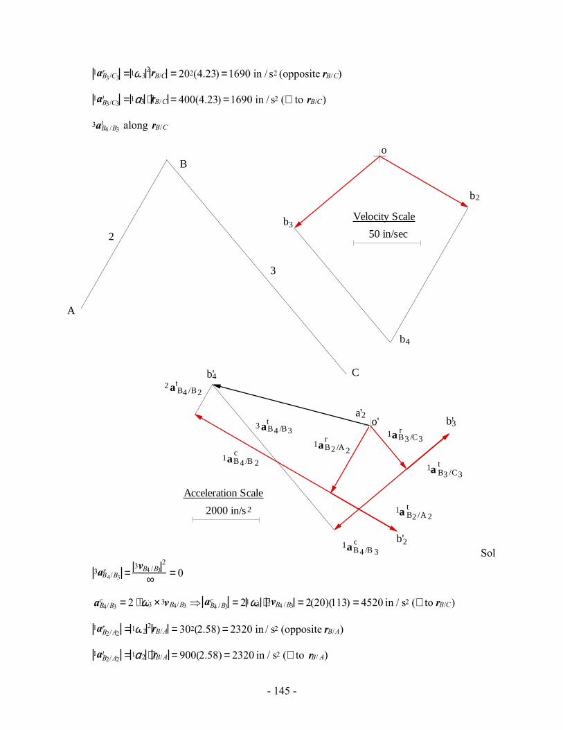
- 145 -
1aB3/C3r =1ω3
2rB/C = 202(4.23) =1690 in / s2 (opposite rB/C)
1aB3/C3t =1α3 ⋅ rB/C = 400(4.23) =1690 in / s2 (⊥ to rB/C)
3aB4 /B3t along rB/C
2
3
A
C
B
b2
50 in/sec
Velocity Scale
o
b3
b4
2000 in/s
Acceleration Scale
2
a'2
1aB2 /A 2r
1aB4 /B 2c
1a B3 /C3t
1aB3 /C3r
o'
b'2
b'3
1a B2 /A 2t
1aB4 /B 3c
3 aB4 /B3t
2 a B4 /B2t
b'4
Sol
3aB4/B3r =
3vB4 /B32
∞ = 0
aB4/B3c = 2 ⋅1ω3 ×3vB4/B3 ⇒ aB4 /B3
c = 21ω3 ⋅ 3vB4 /B3 = 2(20)(113) = 4520 in / s2 (⊥ to rB/C)
1aB2/A2r =1ω2
2rB/A = 302(2.58) = 2320 in / s2 (opposite rB/A)
1aB2/A2t =1α2 ⋅ rB/A = 900(2.58) = 2320 in / s2 (⊥ to rB/ A)

- 146 -
1aB2 /A2t along rB/A
2aB4 /B2r =
2vB4/B22
∞ = 0
aB4/B2c = 2 ⋅1ω2 ×2vB4/ B2 ⇒ aB4 /B2
c = 21ω2 ⋅ 2vB4/B2 = 2(30)(118) = 7080 in / s2 (⊥ to rB/A)
Solve Eq. (2) using the acceleration polygon. Then,
1aB4 = 4890 in / s2 in the direction shown.
Problem 3.40
For the mechanism shown, find ω3, α3, aB3, and the location of the center of curvature of the path that point B3 traces on link 2.
, α 2ω2
A
B
C
D
2
12"
3117˚
AC = 9 inAB = 2 in α2 = 0
ω2 = 50 rad/s
Velocity Analysis:
1vB2 =1vB2/ A2 =1vB3 +1vB2/ B3 (1)
1vB3 =1vB3/ C3
Now, 1vB2 /A2 =1 ω2 ×rB2/ A2 ⇒ 1vB2/ A2 = 1ω2 rB/ A = 50 ⋅2 =100 in / sec (⊥ to rB/A)
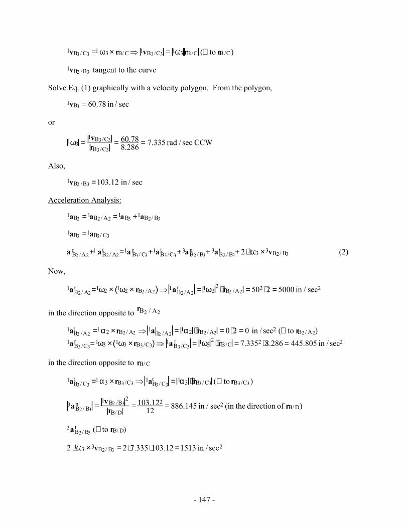
- 147 -
1vB3/ C3 =1 ω3 × rB/ C⇒ 1vB3/C3 = 1ω3 rB/C (⊥ to rB/C)
1vB2 /B3 tangent to the curve
Solve Eq. (1) graphically with a velocity polygon. From the polygon,
1vB3 = 60.78 in / sec
or
1ω3 =1vB3/C3rB3/C3
= 60.788.286 = 7.335 rad / sec CCW
Also,
1vB2 /B3 =103.12 in / sec
Acceleration Analysis:
1aB2 =1aB2/ A2 =1aB3 +1aB2/ B3
1aB3 =1aB3/ C3
a B2 /A2r +1 aB2/ A2
t =1a B3/ C3r +1aB3/C3
t +3aB2/ B3n + 3aB2/ B3
t + 2 ⋅1ω3 ×3vB2/ B3 (2)
Now,
1aB2/ A2r =1ω2 × 1ω2 × rB2 /A2( )⇒ 1aB2/A2
r = 1ω22 ⋅ rB2 /A2 = 502 ⋅2 = 5000 in / sec2
in the direction opposite to rB2 / A2
1aB2 /A2t =1 α2 ×rB2/ A2 ⇒ 1aB2 /A2
t = 1α2 ⋅ rB2/ A2 = 0 ⋅2 = 0 in / sec2 (⊥ to rB2/ A2) 1aB3/C3
r =1ω3 × 1ω3 ×rB3/C3( )⇒ 1aB3/C3r = 1ω3
2 ⋅ rB/C = 7.3352 ⋅8.286 = 445.805 in / sec2
in the direction opposite to rB/ C
1aB3/ C3t =1 α3 ×rB3/C3 ⇒ 1aB3/ C3
t = 1α3 ⋅ rB3/ C3 (⊥ to rB3/C3)
3aB2/ B3n =
1vB2 /B32
rB/ D= 103.122
12 = 886.145 in / sec2 (in the direction of rB/ D)
3aB2/ B3t (⊥ to rB/ D)
2 ⋅1ω3 ×3vB2/ B3 = 2 ⋅7.335 ⋅103.12 =1513 in / sec2
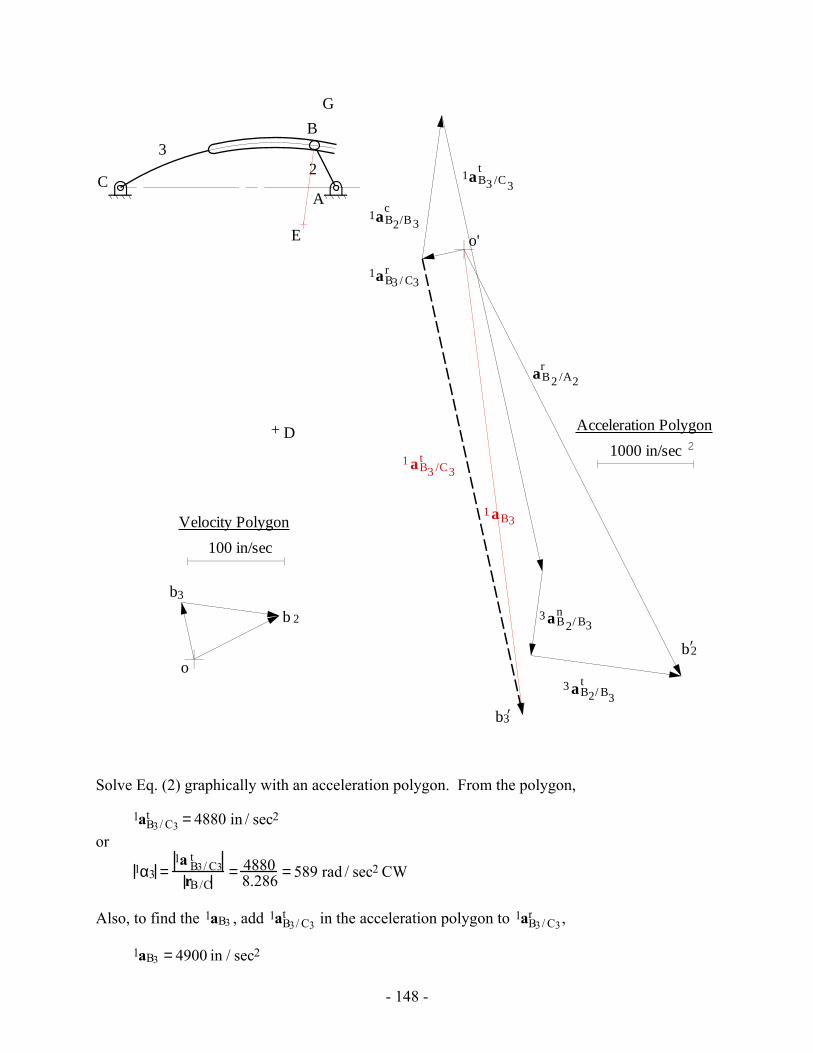
- 148 -
A
B
C
D
23
o
100 in/sec
Velocity Polygon
b 2
b3
aB2 /A2r
1aB3 / C3r
1aB3 /C3
t
1aB2/B3c
3 aB2/ B3n
3 aB2/ B3t
o'
1000 in/sec
Acceleration Polygon2
b2’
b3’
1 aB3
1 aB3 /C3t
G
E
Solve Eq. (2) graphically with an acceleration polygon. From the polygon,
1aB3/ C3t = 4880 in / sec2
or
1α3 =1a B3/ C3
t
rB/C= 4880
8.286 = 589 rad / sec2 CW
Also, to find the 1aB3 , add 1aB3/ C3t in the acceleration polygon to 1aB3/ C3
r ,
1aB3 = 4900 in / sec2
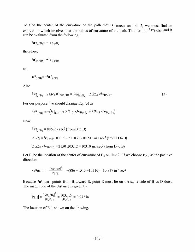
- 149 -
To find the center of the curvature of the path that B3 traces on link 2, we must find an expression which involves that the radius of curvature of the path. This term is 2anB3/B2 and it can be evaluated from the following:
1aB2/ B3= −1aB3/B2
therefore,
1aB2/ B3t = −1aB3/B2
t
and
a B2 /B3n = −1a B3/ B2
n
Also,
3aB2 /B3n +2 ⋅1ω3 ×1vB2/ B3 =−2aB3 /B2
n −2 ⋅1ω2 ×1vB3/B2 (3)
For our purpose, we should arrange Eq. (3) as
2aB3/B2n = − 3aB2 /B3
n + 2 ⋅1ω2 ×1vB3/ B2 +2 ⋅1ω3 ×1vB2/ B3( )
Now,
3aB2 /B3n = 886 in / sec2 (from B to D)
2 ⋅1ω3 ×1vB2/ B3 = 2 ⋅7.335 ⋅103.12 =1513 in / sec2 (from D to B)
2 ⋅1ω2 ×1vB3/ B2 = 2 ⋅50 ⋅103.12 =10310 in / sec2 (from D to B)
Let E be the location of the center of curvature of B3 on link 2. If we choose rD/B as the positive direction,
2anB3/B2 =1vB3/B2
2
rB/E= −(886 −1513 −10310) =10,937 in / sec2
Because 2anB3/B2 points from B toward E, point E must lie on the same side of B as D does. The magnitude of the distance is given by
rB/ E =1vB3/ B2
2
10,937 = 103.12210,937 = 0.972 in
The location of E is shown on the drawing.
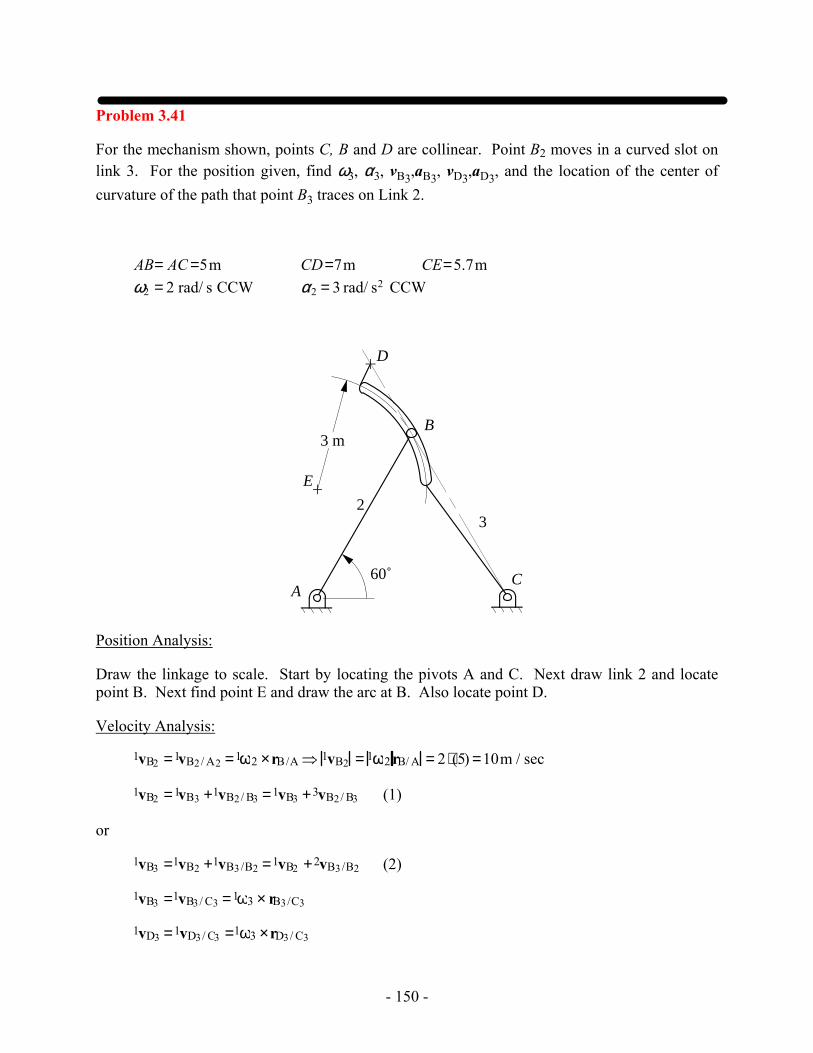
- 150 -
Problem 3.41
For the mechanism shown, points C, B and D are collinear. Point B2 moves in a curved slot on link 3. For the position given, find ω3, α3, vB3,aB3, vD3,aD3, and the location of the center of curvature of the path that point B3 traces on Link 2.
AB= AC =5m CD=7m CE=5.7mω2 = 2 rad/ s CCW α2 = 3 rad/ s2 CCW
CA
23
60˚
D
B
E
3 m
Position Analysis:
Draw the linkage to scale. Start by locating the pivots A and C. Next draw link 2 and locate point B. Next find point E and draw the arc at B. Also locate point D.
Velocity Analysis:
1vB2 =1vB2/ A2 =1ω2 ×rB/A ⇒ 1vB2 = 1ω2 rB/ A = 2 ⋅(5) =10m / sec
1vB2 =1vB3 +1vB2/ B3 =1vB3 +3vB2/ B3 (1)
or
1vB3 =1vB2 +1vB3/B2 =1vB2 +2vB3/B2 (2)
1vB3 =1vB3/ C3 =1ω3 × rB3/C3
1vD3 =1vD3/ C3 =1ω3 ×rD3/ C3
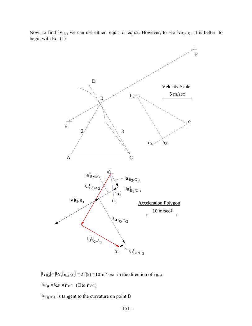
- 151 -
Now, to find 1vB3 , we can use either equ.1 or equ.2. However, to see 1vB3/B2 , it is better to begin with Eq..(1).
o
b2
b3d3
5 m/sec
Velocity Scale
A
E
C
B
D
2 3
o'
1aB2 /A 2t
b2’
10 m/sec
Acceleration Polygon
2
3aB2 /B3
caB2/B3
1aB3/C 3t
1aB3/C 3r
1aB2 /A 2r
b3’
3d'
na B2/B3
1aB3 /C 3t
F
1vB2 = 1ω2 rB2 /A2 = 2 ⋅(5) =10m / sec in the direction of rB/ A
1vB3 =1ω3 ×rB/ C (⊥ to rB/ C)
1vB2 /B3 is tangent to the curvature on point B
- 152 -
Solve Eq. (1) graphically with a velocity polygon. The velocity directions can be gotten directly from the polygon. The magnitudes are given by:
1vB2/ B3 = 8.66m / sec.
Also,
1vB3 = 5 m / sec ⇒ 1ω3 =1vB3rB/C
= 55 =1rad / sec
From the directions given in the position and velocity polygons
1ω3 =1 rad / sec CCW
To compute the velocity of D3,
1vD3 =1vD3/ C3 =1ω3 ×rD3/ C3 ⇒ 1vD3 = 1ω3 rB3/C3 =1 ⋅(7) = 7m / sec
Acceleration Analysis:
1αB2 =1αB2/ A2 =1αB2/ A2t +1αB2/ A2
r
1αB2 =1αB3 +1αB2/ B3
also
1αB2/ A2 = 1αB3/C3 +1αB2 /B3
Expanding the equation,
1αB2/A2t +1αB2/ A2
r = 1αB3/C3r +1αB3/ C3
t +3αB2/ B3 +1αB2 /B3n +1αB2/ B3
c
Or
1aB2/ A2r +1aB2/A2
t =1aB3/C3r +1aB3/C3
t +3aB2/ B3 +2 ⋅1ω3 ×3vB2 /B3 +1aB2 /B3n (2)
Now,
1aB2/ A2r =1ω2 × 1ω2 × rB/ A( )⇒ 1a B2 /A2
r = 1ω22 ⋅ rB/ A = 2.02 ⋅5 = 20 m / sec2
in the direction of rB/ A
1aB2 /A2t =1α2 × rB/ A ⇒ 1aB2/ A2
t = 1α2 ⋅ rB/A = 3.0 ⋅5 =15 m / sec2(⊥ to rB/A)
1aB3/C3r =1ω3 × 1ω3 ×rB/C( )⇒ 1aB3/C3
r = 1ω32 ⋅ rB/ C =12 ⋅5 = 5 m / sec2
in the direction opposite to rB/ C
- 153 -
1aB3/ C3t =1α3 × rB/C ⇒ 1aB3/C3
t = 1α3 ⋅ rB/C (⊥ to rB/C)
1aB2 /B3c = 2 ⋅1ω3 ×3vB2/ B3 = 2 ⋅1 ⋅8.66 =17.32 m / sec2 (⊥ to rB/C)
1aB2 /B3n =
3vB2/ B32
rB/ E= 8.662
3 = 25m / sec2 from B to E
3aB2 /B3 in the direction of rB/ C
Solve Eq. (2) graphically with a acceleration polygon. From the polygon,
1α3 =1aB3/C3
t
rB/C= 0.2131
5 = 0.0426 rad / sec2
From directions given in the polygon,
1α3 = 0.0426 rad / sec2 CCW
The accelerations of D3 and B3 can be computed by image. The direction of the accelerations are given in the polygon and the magnitudes of the accelerations are
1aD3 = 8.00 m / sec2
1aB3 = 5.71m / sec2
To find the center of the curvature of the path that B3 traces on link 2, we must find an expression which involves that the radius of curvature of the path. This term is 2anB3/B2 and it can be evaluated from the following:
1aB2/ B3= −1aB3/B2
therefore,
1aB2/ B3t = −1aB3/B2
t
and
a B2 /B3n = −1a B3/ B2
n
Also,
3aB2 /B3n +2 ⋅1ω3 ×1vB2/ B3 =−2aB3 /B2
n −2 ⋅1ω2 ×1vB3/B2 (3)
For our purpose, we should arrange Eq. (3) as
2aB3/B2n = − 3aB2 /B3
n + 2 ⋅1ω2 ×1vB3/ B2 +2 ⋅1ω3 ×1vB2/ B3( )
Now,
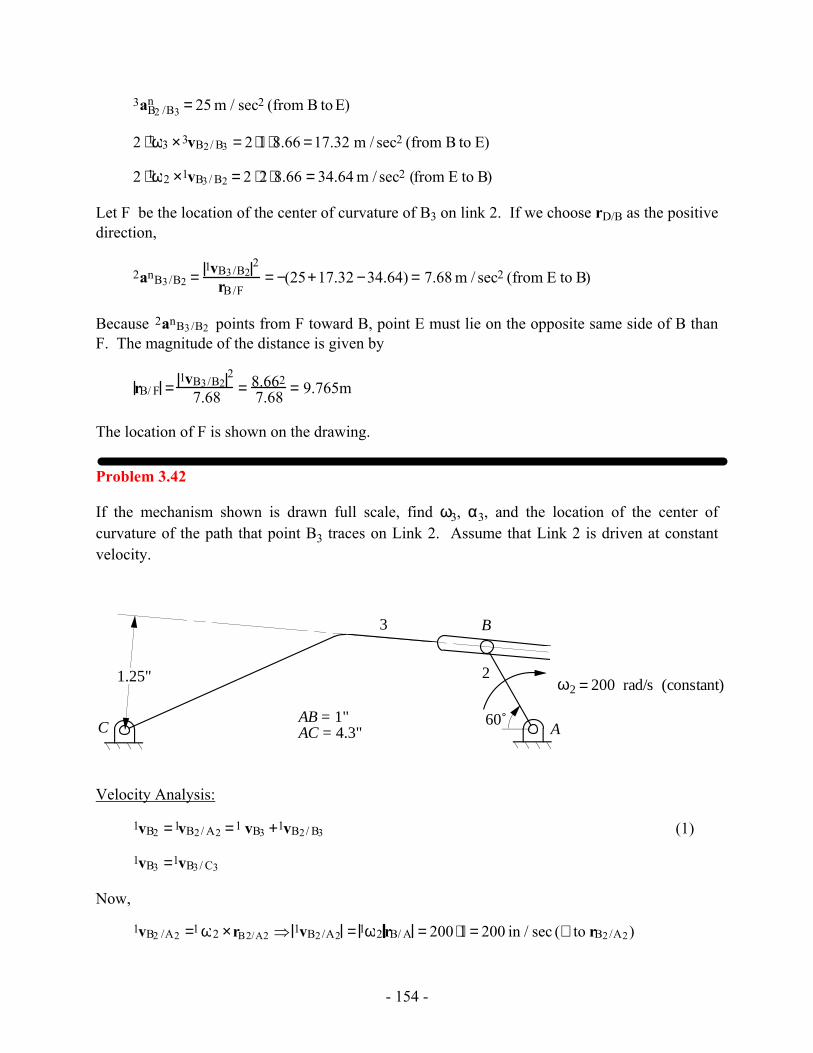
- 154 -
3aB2 /B3n = 25 m / sec2 (from B to E)
2 ⋅1ω3 ×3vB2/ B3 = 2 ⋅1 ⋅8.66 =17.32 m / sec2 (from B to E)
2 ⋅1ω2 ×1vB3/ B2 = 2 ⋅2 ⋅8.66 = 34.64 m / sec2 (from E to B)
Let F be the location of the center of curvature of B3 on link 2. If we choose rD/B as the positive direction,
2anB3/B2 =1vB3/B2
2
rB/F= −(25+17.32 −34.64) = 7.68 m / sec2 (from E to B)
Because 2anB3/B2 points from F toward B, point E must lie on the opposite same side of B than F. The magnitude of the distance is given by
rB/ F =1vB3/B2
2
7.68 = 8.6627.68 = 9.765m
The location of F is shown on the drawing.
Problem 3.42
If the mechanism shown is drawn full scale, find ω3, α3, and the location of the center of curvature of the path that point B3 traces on Link 2. Assume that Link 2 is driven at constant velocity.
2
3
AC
B
ω2 = 200 rad/s (constant)
AB = 1"AC = 4.3"
60˚
1.25"
Velocity Analysis:
1vB2 =1vB2/ A2 =1 vB3 +1vB2/ B3 (1)
1vB3 =1vB3/ C3
Now,
1vB2 /A2 =1 ω2 ×rB2/A2 ⇒ 1vB2/A2 = 1ω2 rB/ A = 200 ⋅1 = 200 in / sec (⊥ to rB2/A2)
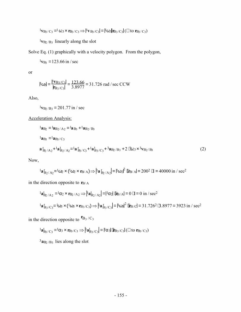
- 155 -
1vB3/ C3 =1 ω3 × rB3/ C3⇒ 1vB3/C3 = 1ω3 rB3/C3 (⊥ to rB3/ C3)
1vB2 /B3 linearly along the slot
Solve Eq. (1) graphically with a velocity polygon. From the polygon,
1vB3 =123.66 in / sec
or
1ω3 =1vB3/C3rB3/C3
= 123.663.8977 = 31.726 rad / sec CCW
Also,
1vB2 /B3 = 201.77 in / sec
Acceleration Analysis:
1aB2 =1aB2/ A2 =1aB3 +1aB2/ B3
1aB3 =1aB3/ C3
a B2 /A2r +1aB2/ A2
t =1a B3/ C3r +1aB3/C3
t +3aB2 /B3 +2 ⋅1ω3 ×3vB2/ B3 (2)
Now,
1aB2/ A2r =1ω2 × 1ω2 × rB/ A( )⇒ 1a B2 /A2
r = 1ω22 ⋅ rB/ A = 2002 ⋅1 = 40000 in / sec2
in the direction opposite to rB/ A
1aB2 /A2t =1α2 × rB2 /A2 ⇒ 1aB2/ A2
t = 1α2 ⋅ rB/A = 0 ⋅1= 0 in / sec2
1aB3/C3r =1ω3 × 1ω3 ×rB3/C3( )⇒ 1aB3/C3
r = 1ω32 ⋅ rB/C = 31.7262 ⋅3.8977 = 3923 in / sec2
in the direction opposite to rB3 / C3
1aB3/ C3t =1α3 × rB3/C3 ⇒ 1aB3/C3
t = 1α3 ⋅ rB3/C3 (⊥ to rB3/ C3)
3aB2 /B3 lies along the slot
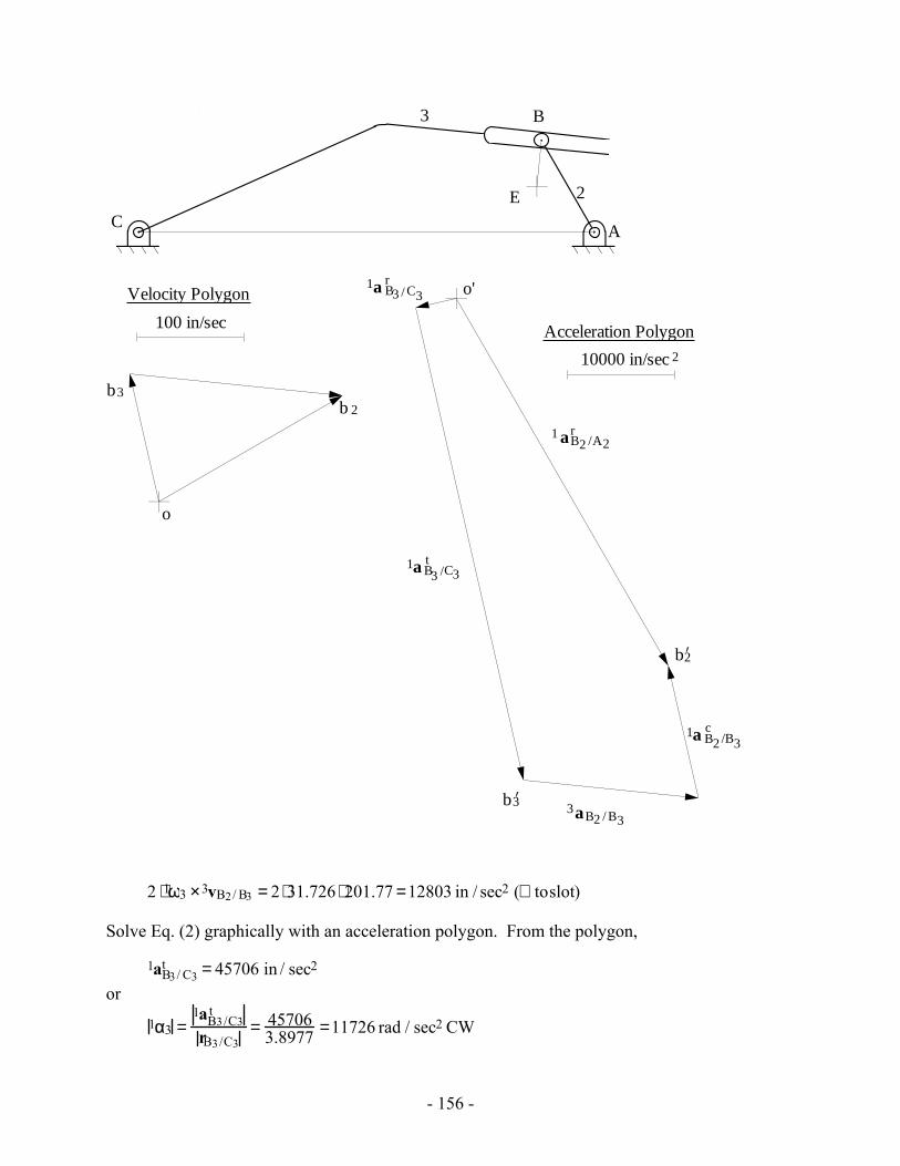
- 156 -
2
3
AC
B
b 2b3
o
100 in/sec
Velocity Polygon
1 aB2 /A2r
1a B3 / C3r
1a B3 /C3t
3aB2 / B3
1a B2 /B3c
o'
10000 in/sec
Acceleration Polygon2
E
b3’
b2’
2 ⋅1ω3 ×3vB2/ B3 = 2 ⋅31.726 ⋅ 201.77 =12803 in / sec2 (⊥ toslot)
Solve Eq. (2) graphically with an acceleration polygon. From the polygon,
1aB3/ C3t = 45706 in / sec2
or
1α3 =1aB3/C3
t
rB3/C3= 45706
3.8977 =11726 rad / sec2 CW
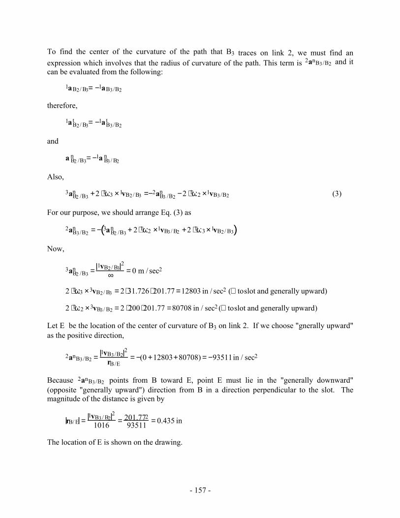
- 157 -
To find the center of the curvature of the path that B3 traces on link 2, we must find an expression which involves that the radius of curvature of the path. This term is 2anB3/B2 and it can be evaluated from the following:
1aB2/ B3= −1aB3/B2
therefore,
1aB2/ B3t = −1aB3/B2
t
and
a B2 /B3n = −1a B3/ B2
n
Also,
3aB2 /B3n +2 ⋅1ω3 ×1vB2/ B3 =−2aB3 /B2
n −2 ⋅1ω2 ×1vB3/B2 (3)
For our purpose, we should arrange Eq. (3) as
2aB3/B2n = − 3aB2 /B3
n + 2 ⋅1ω2 ×1vB3/ B2 +2 ⋅1ω3 ×1vB2/ B3( )
Now,
3aB2 /B3n =
1vB2/ B32
∞ = 0 m / sec2
2 ⋅1ω3 ×3vB2/ B3 = 2 ⋅31.726 ⋅ 201.77 =12803 in / sec2 (⊥ toslot and generally upward)
2 ⋅1ω2 ×3vB3/ B2 = 2 ⋅200 ⋅201.77 =80708 in / sec2 (⊥ toslot and generally upward)
Let E be the location of the center of curvature of B3 on link 2. If we choose "gnerally upward" as the positive direction,
2anB3/B2 =1vB3/B2
2
rB/E= −(0 +12803+80708) = −93511in / sec2
Because 2anB3/B2 points from B toward E, point E must lie in the "generally downward" (opposite "generally upward") direction from B in a direction perpendicular to the slot. The magnitude of the distance is given by
rB/ E =1vB3/ B2
2
1016 = 201.77293511 = 0.435 in
The location of E is shown on the drawing.
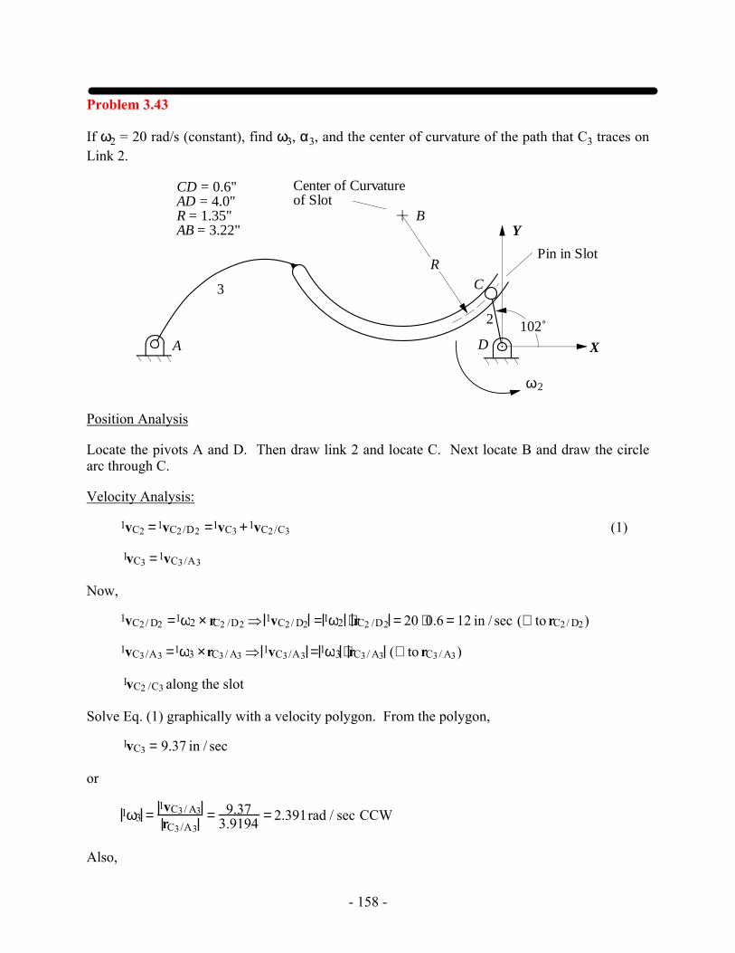
- 158 -
Problem 3.43
If ω2 = 20 rad/s (constant), find ω3, α3, and the center of curvature of the path that C3 traces on Link 2.
A
C
B
D
Pin in Slot
2
3
Center of Curvature of Slot
2ω
R
X
Y
CD = 0.6"AD = 4.0"R = 1.35"AB = 3.22"
102˚
Position Analysis
Locate the pivots A and D. Then draw link 2 and locate C. Next locate B and draw the circle arc through C.
Velocity Analysis:
1vC2 =1vC2/D2 =1vC3 +1vC2/C3 (1)
1vC3 =1vC3/A3
Now,
1vC2/ D2 =1ω2 × rC2 /D2 ⇒ 1vC2/ D2 =1ω2 ⋅ rC2 /D2 = 20 ⋅0.6 = 12 in / sec (⊥ to rC2/ D2)
1vC3/A3 =1ω3 ×rC3/ A3 ⇒ 1vC3/A3 =1ω3 ⋅ rC3/ A3 (⊥ to rC3/ A3)
1vC2 /C3 along the slot
Solve Eq. (1) graphically with a velocity polygon. From the polygon,
1vC3 = 9.37 in / sec
or
1ω3 =1vC3/ A3rC3/A3
= 9.373.9194 = 2.391rad / sec CCW
Also,
- 159 -
1vC2/C3 =15.66 in / sec
Acceleration Analysis:
1aC2 =1aC2/D2 =1aC3 +1aC2/C3
1aC3 =1aC3/A3
1aC2/ D2r +1aC2/ D2
t =1aC3/ A3r +1aC3/ A3
t +3aC2 /C3r +3aC2/ C3
t +2 ⋅1ω3 ×3vC2 /C3 (2) Now, 1aC2/ D2
r =1ω2 × 1ω2 ×rC2/ D2( )⇒ 1aC2/ D2r = 1ω2
2 ⋅ rC2/ D2 = 202 ⋅0.6 = 240 in / sec2
in the direction of rC2/ D2
1aC2/ D2t =1α2 × rC2/ D2 ⇒ 1aC2 /D2
t = 1α2 ⋅ rC2/D2 = 0 ⋅0.6 = 0 in / sec2
1aC3/A3r =1ω3 × 1ω3 ×rC3/ A3( )⇒ 1aC3/ A3
r = 1ω32 ⋅ rC3/ A3 = 2.3912 ⋅3.9194 = 22.407 in / sec2
in the direction of rC3/A3
1aC3/A3t =1α3 × rC3/ A3 ⇒ 1aC3/ A3
t = 1α3 ⋅ rC3/ A3 (⊥ to rC3/A3)
3aC2/ C3r =
1vC2/ C32
rC3/B3= 15.662
1.35 =181.656 in / sec2 in the direction of rC3/B3
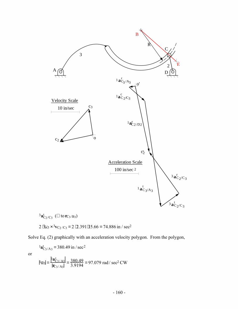
- 160 -
A
C
B
D
2
3
R
c2
c3
c2’
1aC2 /D2r
1 aC3 /A3r
3 aC2/C3r
1aC2/C3c
1 aC3/A3t
E
o'
100 in/sec
Acceleration Scale
2
o
10 in/sec
Velocity Scale
3 aC2/C3t
3aC2/C3t (⊥ to rC3/B3)
2 ⋅1ω3 ×3vC2 /C3 = 2 ⋅2.391⋅15.66 = 74.886 in / sec2
Solve Eq. (2) graphically with an acceleration velocity polygon. From the polygon,
1aC3/A3t = 380.49 in / sec2
or
1α3 =1aC3/ A3
t
rC3/ A3= 380.49
3.9194 = 97.079 rad / sec2 CW
- 161 -
To find the center of the curvature of the path that C3 traces on link 2, we must find an
expression which involves that the radius of curvature of the path. This term is 2 aC3 /C2
n and it
can be evaluated from the following:
1aC3/C2 =−1aC2 /C3
therefore,
1aC3/C2t =−1aC2 /C3
t
and
1aC3/C2n =−1aC2/C3
n
Also,
2aC3/C2n +2 ⋅1ω2 ×1vC3/C2 =−3aC2/C3
n − 2 ⋅1ω3 ×1vC2/ C3 (3)
For our purpose, we should arrange eq.3 as
2aC3/C2n = − 3aC2/ C3
n + 2 ⋅1ω3 ×1vC2 /C3 +2 ⋅1ω2 ×1vC3/C2( )
Now,
3aC2/C3n =
1vC2 /C32
rC3/ B3= 15.662
1.35 =181.656 in / sec2
2 ⋅1ω3 ×3vC2 /C3 = 2 ⋅2.391⋅15.66 = 74.886 in / sec2
2 ⋅1ω2 ×2vC3/ C2 = 2 ⋅20 ⋅15.66 = 626.4 in / sec2
If we choose BC as positive direction,
2aC3/C2n =
1vC3/C22
rC3/E3= −(181.656 − 74.886 +626.4) = −733.17 in / sec2
So,
rC3/E3 =1vC3/C2
2
−733.17 = 15.662−733.17 = −0.334 in
Therefore, the center of the curvature of the path that B3 traces on link 2 is in opposite direction of BC as shown in the sketch.
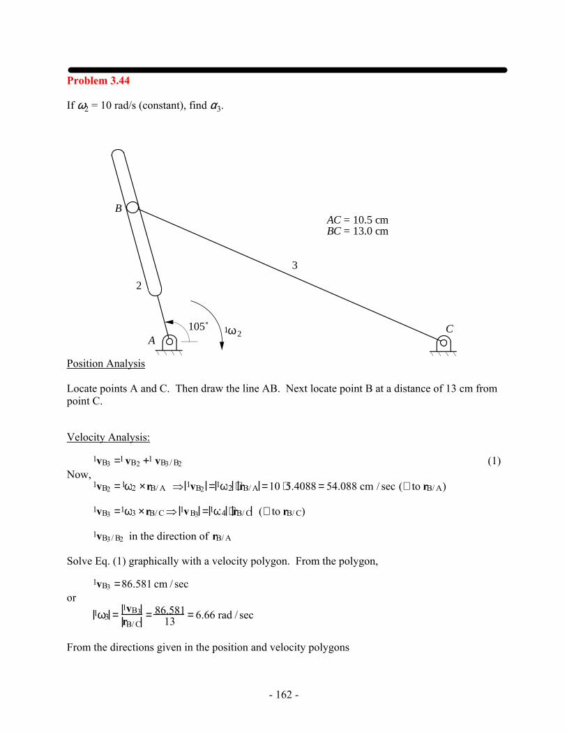
- 162 -
Problem 3.44
If ω2 = 10 rad/s (constant), find α3.
2
3
AC
B
ω1 2105˚
AC = 10.5 cmBC = 13.0 cm
Position Analysis Locate points A and C. Then draw the line AB. Next locate point B at a distance of 13 cm from point C.
Velocity Analysis:
1vB3 =1 vB2 +1 vB3/ B2 (1) Now, 1vB2 =1ω2 ×rB/ A ⇒ 1vB2 =1ω2 ⋅ rB/ A =10 ⋅5.4088 = 54.088 cm / sec (⊥ to rB/ A)
1vB3 =1ω3 ×rB/ C⇒ 1vB3 =1ω4 ⋅ rB/ C (⊥ to rB/ C)
1vB3/ B2 in the direction of rB/ A
Solve Eq. (1) graphically with a velocity polygon. From the polygon,
1vB3 =86.581 cm / sec or 1ω3 =
1vB3rB/ C
= 86.58113 = 6.66 rad / sec
From the directions given in the position and velocity polygons
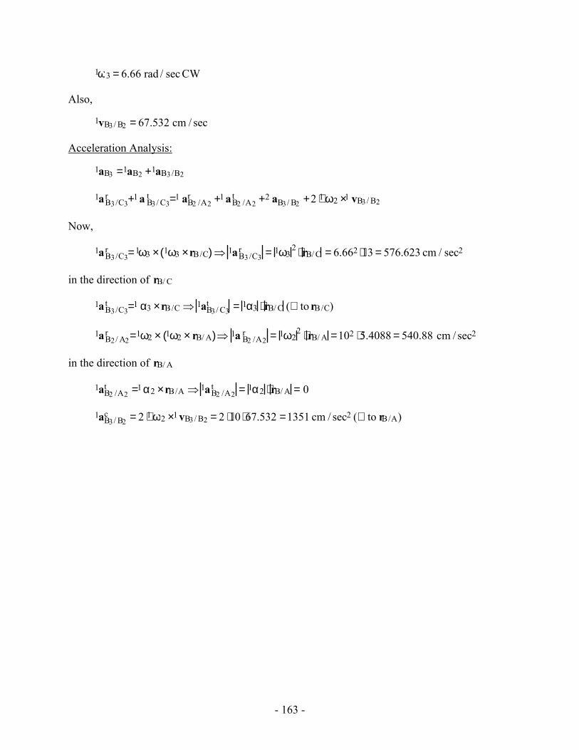
- 163 -
1ω3 = 6.66 rad / sec CW
Also,
1vB3/ B2 = 67.532 cm / sec
Acceleration Analysis:
1aB3 =1aB2 +1aB3/B2
1aB3/C3r +1 a B3/ C3
t =1 aB2 /A2r +1 aB2 /A2
t +2 aB3/ B2 +2 ⋅1 ω2 ×1 vB3/ B2
Now,
1aB3/C3r =1ω3 × 1ω3 ×rB/C( )⇒ 1aB3/C3
r = 1ω32 ⋅ rB/ C = 6.662 ⋅13 = 576.623 cm / sec2
in the direction of rB/ C
1aB3/C3t =1 α3 ×rB/C ⇒ 1aB3/ C3
t = 1α3 ⋅ rB/ C (⊥ to rB/C)
1aB2/ A2r =1ω2 × 1ω2 × rB/ A( )⇒ 1a B2 /A2
r = 1ω22 ⋅ rB/ A =102 ⋅5.4088 = 540.88 cm / sec2
in the direction of rB/ A
1aB2 /A2t =1 α2 ×rB/A ⇒ 1aB2 /A2
t = 1α2 ⋅ rB/ A = 0
1aB3/ B2c = 2 ⋅1 ω2 ×1 vB3/ B2 = 2 ⋅10 ⋅67.532 =1351 cm / sec2 (⊥ to rB/A)
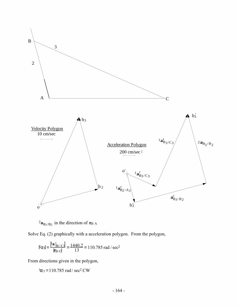
- 164 -
Velocity Polygon
2
3
A C
B
10 cm/sec
b 2
b3
o'
200 cm/sec
Acceleration Polygon2
b2’
2 aB3 / B2
b3’
o
caB3 / B2
1 raB2 / A2
1 raB3 / C3
1 taB3 /C3
2aB3/B2 in the direction of rB/ A
Solve Eq. (2) graphically with a acceleration polygon. From the polygon,
1α3 =1a B3/ C3
t
rB/C= 1440.2
13 = 110.785 rad / sec2
From directions given in the polygon,
1α3 =110.785 rad / sec2 CW
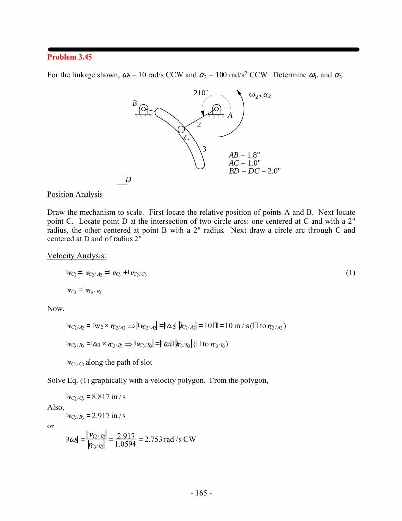
- 165 -
Problem 3.45
For the linkage shown, ω2 = 10 rad/s CCW and α2 = 100 rad/s2 CCW. Determine ω3, and α3.
2
3
A
C
B
D
α2ω2 ,
AB = 1.8"AC = 1.0"BD = DC = 2.0"
210˚
Position Analysis Draw the mechanism to scale. First locate the relative position of points A and B. Next locate point C. Locate point D at the intersection of two circle arcs: one centered at C and with a 2" radius, the other centered at point B with a 2" radius. Next draw a circle arc through C and centered at D and of radius 2"
Velocity Analysis:
1vC2 =1 vC2/ A2 =1 vC3 +1vC2/C3 (1)
1vC3 =1vC3/ B3
Now,
1vC2/A2 = 1w2 × rC2/A2 ⇒ 1vC2/ A2 =1ω2 ⋅ rC2/A2 =10 ⋅1 =10 in / s (⊥ to rC2 /A2 )
1vC3 /B3 =1ω3 × rC3/B3 ⇒ 1vC3/B3 =1ω3 ⋅ rC3/B3 (⊥ to rC3/B3)
1vC2/C3 along the path of slot
Solve Eq. (1) graphically with a velocity polygon. From the polygon,
1vC2/C3 = 8.817 in / s Also, 1vC3 /B3 = 2.917 in / s or
1ω3 =1vC3/ B3
rC3/B3= 2.917
1.0594 = 2.753 rad / s CW
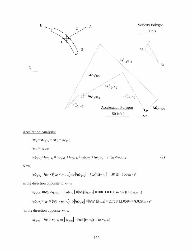
- 166 -
2
3
A
C
B
D
3aC2/ C3r
o
50 in/s
Acceleration Polygon
2
o
10 in/s
Velocity Polygon
c2
c3
1aC2/A2t
3aC2/ C3t
1aC2/A2r
1aC3/B3t
1aC 3/B3r
aC 2/C3c
c'2
Accelration Analysis:
1aC2 =1aC2/A2 =1aC3 +1aC2 /C3
1aC3 =1aC3/B3
1aC2/A2r +1aC2/A2
t =1aC3/B3r +1aC3/ B3
t +3aC2/C3r +3aC2 /C3
t + 2 1ω3 ×1vC2/C3 (2)
Now,
1aC2/A2r =1ω2 × 1ω2 × rC2/ A2( )⇒ 1aC2/A2
r = 1ω22 ⋅ rC2 /A2 =102 ⋅1 =100 in / s2
in the direction opposite to rC2 /A2
1aC2/ A2t =1α2 ×rC2 /A2 ⇒ 1aC2/ A2
t = 1α2 ⋅ rC2/A2 =100 ⋅1 =100 in / s2 (⊥ to rC2/A2)
1aC3/B3r =1ω3 × 1ω3 ×rC3/B3( )⇒ 1aC3/B3
r = 1ω32 ⋅ rC3/B3 = 2.7532 ⋅1.0594 = 8.029 in / s2
in the direction opposite rC3/B3
1aC3/B3t =1α3 × rC3/B3 ⇒ 1aC3/B3
t = 1α3 ⋅ rC3/B3 (⊥ to rC3/ B3)
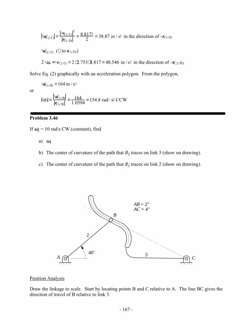
- 167 -
3aC2/C3r =
1vC2 /C32
rC3 /D3= 8.8172
2 = 38.87 in / s2 in the direction of -rC3/D3
3aC2 /C3t (⊥ to rC3/D3)
2 1ω3 ×1vC2/C3 = 2 ⋅2.753 ⋅8.817 = 48.546 in / s2 in the direction of -rC3/D3
Solve Eq. (2) graphically with an acceleration polygon. From the polygon,
1aC3/B3t =164 in / s2
or
1α3 =1aC3/B3
t
rC3/B3= 164
1.0594 =154.8 rad / s2 CCW
Problem 3.46
If ω2 = 10 rad/s CW (constant), find
a) ω3
b) The center of curvature of the path that B2 traces on link 3 (show on drawing).
c) The center of curvature of the path that B3 traces on link 2 (show on drawing).
B
2
3A C40˚
AB = 2"AC = 4"
Position Analysis
Draw the linkage to scale. Start by locating points B and C relative to A. The line BC gives the direction of travel of B relative to link 3.
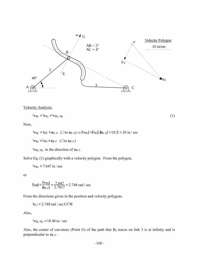
- 168 -
B
2
3A C
AB = 2"AC = 4"
40°
o
b2
b3
10 in/sec
Velocity PolygonG
E
∞
Velocity Analysis:
1vB2 =1vB3 +1vB2/ B3 (1)
Now,
1vB2 =1ω2 ×rB/ A (⊥ to rB/ A)⇒ 1vB2 =1ω2 ⋅ rB/A =10 ⋅2 = 20 in / sec
1vB3 =1ω3 ×rB/ C (⊥ to rB/ C)
1vB2 /B3 in the direction of rB/ C
Solve Eq. (1) graphically with a velocity polygon. From the polygon,
1vB3 = 7.647 in / sec
or
1ω3 =1vB3rB/ C
= 7.6472.7827 = 2.748 rad / sec
From the directions given in the position and velocity polygons
1ω3 = 2.748 rad / sec CCW
Also,
1vB2 /B3 =18.48 in / sec
Also, the center of curvature (Point G) of the path that B2 traces on link 3 is at infinity and is perpendicular to rB/ C .
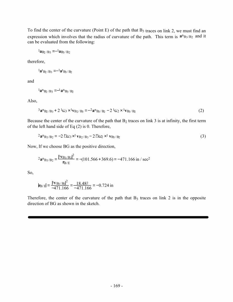
- 169 -
To find the center of the curvature (Point E) of the path that B3 traces on link 2, we must find an expression which involves that the radius of curvature of the path. This term is anB3/B2 and it can be evaluated from the following:
1aB2 /B3 =−1aB3/ B2
therefore,
1atB2 /B3 =−1atB3 / B2
and
1anB2 /B3 =−1anB3/ B2
Also,
3anB2 /B3 + 2 1ω3 ×1vB2/ B3 =−2anB3/ B2 −2 1ω2 ×1vB3/ B2 (2)
Because the center of the curvature of the path that B2 traces on link 3 is at infinity, the first term of the left hand side of Eq (2) is 0. Therefore,
2anB3/B2 = −2 ⋅1 ω3 ×1 vB2/ B3 − 2 ⋅1 ω2 ×1 vB3/ B2 (3)
Now, If we choose BG as the positive direction,
2anB3/B2 =1vB3/B2
2
rB/E= −(101.566 +369.6) = −471.166 in / sec2
So,
rB/ E =1vB3/ B2
2
−471.166 = 18.482−471.166 = −0.724 in
Therefore, the center of the curvature of the path that B3 traces on link 2 is in the opposite direction of BG as shown in the sketch.